EP4349465A1 - Hollow fiber membrane module and dehumidification/humidification device - Google Patents
Hollow fiber membrane module and dehumidification/humidification device Download PDFInfo
- Publication number
- EP4349465A1 EP4349465A1 EP22815837.4A EP22815837A EP4349465A1 EP 4349465 A1 EP4349465 A1 EP 4349465A1 EP 22815837 A EP22815837 A EP 22815837A EP 4349465 A1 EP4349465 A1 EP 4349465A1
- Authority
- EP
- European Patent Office
- Prior art keywords
- hollow fiber
- end side
- membrane module
- fiber membrane
- annular gap
- Prior art date
- Legal status (The legal status is an assumption and is not a legal conclusion. Google has not performed a legal analysis and makes no representation as to the accuracy of the status listed.)
- Pending
Links
Images

Classifications
-
- B—PERFORMING OPERATIONS; TRANSPORTING
- B01—PHYSICAL OR CHEMICAL PROCESSES OR APPARATUS IN GENERAL
- B01D—SEPARATION
- B01D63/00—Apparatus in general for separation processes using semi-permeable membranes
- B01D63/02—Hollow fibre modules
- B01D63/04—Hollow fibre modules comprising multiple hollow fibre assemblies
-
- B—PERFORMING OPERATIONS; TRANSPORTING
- B01—PHYSICAL OR CHEMICAL PROCESSES OR APPARATUS IN GENERAL
- B01D—SEPARATION
- B01D53/00—Separation of gases or vapours; Recovering vapours of volatile solvents from gases; Chemical or biological purification of waste gases, e.g. engine exhaust gases, smoke, fumes, flue gases, aerosols
- B01D53/26—Drying gases or vapours
- B01D53/268—Drying gases or vapours by diffusion
-
- B—PERFORMING OPERATIONS; TRANSPORTING
- B01—PHYSICAL OR CHEMICAL PROCESSES OR APPARATUS IN GENERAL
- B01D—SEPARATION
- B01D63/00—Apparatus in general for separation processes using semi-permeable membranes
- B01D63/02—Hollow fibre modules
- B01D63/021—Manufacturing thereof
- B01D63/022—Encapsulating hollow fibres
-
- B—PERFORMING OPERATIONS; TRANSPORTING
- B01—PHYSICAL OR CHEMICAL PROCESSES OR APPARATUS IN GENERAL
- B01D—SEPARATION
- B01D53/00—Separation of gases or vapours; Recovering vapours of volatile solvents from gases; Chemical or biological purification of waste gases, e.g. engine exhaust gases, smoke, fumes, flue gases, aerosols
- B01D53/22—Separation of gases or vapours; Recovering vapours of volatile solvents from gases; Chemical or biological purification of waste gases, e.g. engine exhaust gases, smoke, fumes, flue gases, aerosols by diffusion
- B01D53/228—Separation of gases or vapours; Recovering vapours of volatile solvents from gases; Chemical or biological purification of waste gases, e.g. engine exhaust gases, smoke, fumes, flue gases, aerosols by diffusion characterised by specific membranes
-
- B—PERFORMING OPERATIONS; TRANSPORTING
- B01—PHYSICAL OR CHEMICAL PROCESSES OR APPARATUS IN GENERAL
- B01D—SEPARATION
- B01D53/00—Separation of gases or vapours; Recovering vapours of volatile solvents from gases; Chemical or biological purification of waste gases, e.g. engine exhaust gases, smoke, fumes, flue gases, aerosols
- B01D53/26—Drying gases or vapours
- B01D53/265—Drying gases or vapours by refrigeration (condensation)
-
- B—PERFORMING OPERATIONS; TRANSPORTING
- B01—PHYSICAL OR CHEMICAL PROCESSES OR APPARATUS IN GENERAL
- B01D—SEPARATION
- B01D63/00—Apparatus in general for separation processes using semi-permeable membranes
- B01D63/02—Hollow fibre modules
-
- H—ELECTRICITY
- H01—ELECTRIC ELEMENTS
- H01M—PROCESSES OR MEANS, e.g. BATTERIES, FOR THE DIRECT CONVERSION OF CHEMICAL ENERGY INTO ELECTRICAL ENERGY
- H01M8/00—Fuel cells; Manufacture thereof
- H01M8/04—Auxiliary arrangements, e.g. for control of pressure or for circulation of fluids
-
- H—ELECTRICITY
- H01—ELECTRIC ELEMENTS
- H01M—PROCESSES OR MEANS, e.g. BATTERIES, FOR THE DIRECT CONVERSION OF CHEMICAL ENERGY INTO ELECTRICAL ENERGY
- H01M8/00—Fuel cells; Manufacture thereof
- H01M8/04—Auxiliary arrangements, e.g. for control of pressure or for circulation of fluids
- H01M8/04082—Arrangements for control of reactant parameters, e.g. pressure or concentration
- H01M8/04089—Arrangements for control of reactant parameters, e.g. pressure or concentration of gaseous reactants
- H01M8/04119—Arrangements for control of reactant parameters, e.g. pressure or concentration of gaseous reactants with simultaneous supply or evacuation of electrolyte; Humidifying or dehumidifying
- H01M8/04126—Humidifying
- H01M8/04149—Humidifying by diffusion, e.g. making use of membranes
-
- B—PERFORMING OPERATIONS; TRANSPORTING
- B01—PHYSICAL OR CHEMICAL PROCESSES OR APPARATUS IN GENERAL
- B01D—SEPARATION
- B01D53/00—Separation of gases or vapours; Recovering vapours of volatile solvents from gases; Chemical or biological purification of waste gases, e.g. engine exhaust gases, smoke, fumes, flue gases, aerosols
- B01D53/22—Separation of gases or vapours; Recovering vapours of volatile solvents from gases; Chemical or biological purification of waste gases, e.g. engine exhaust gases, smoke, fumes, flue gases, aerosols by diffusion
- B01D2053/221—Devices
- B01D2053/223—Devices with hollow tubes
-
- B—PERFORMING OPERATIONS; TRANSPORTING
- B01—PHYSICAL OR CHEMICAL PROCESSES OR APPARATUS IN GENERAL
- B01D—SEPARATION
- B01D53/00—Separation of gases or vapours; Recovering vapours of volatile solvents from gases; Chemical or biological purification of waste gases, e.g. engine exhaust gases, smoke, fumes, flue gases, aerosols
- B01D53/22—Separation of gases or vapours; Recovering vapours of volatile solvents from gases; Chemical or biological purification of waste gases, e.g. engine exhaust gases, smoke, fumes, flue gases, aerosols by diffusion
- B01D2053/221—Devices
- B01D2053/223—Devices with hollow tubes
- B01D2053/224—Devices with hollow tubes with hollow fibres
-
- B—PERFORMING OPERATIONS; TRANSPORTING
- B01—PHYSICAL OR CHEMICAL PROCESSES OR APPARATUS IN GENERAL
- B01D—SEPARATION
- B01D2257/00—Components to be removed
- B01D2257/80—Water
-
- B—PERFORMING OPERATIONS; TRANSPORTING
- B01—PHYSICAL OR CHEMICAL PROCESSES OR APPARATUS IN GENERAL
- B01D—SEPARATION
- B01D2313/00—Details relating to membrane modules or apparatus
- B01D2313/04—Specific sealing means
-
- B—PERFORMING OPERATIONS; TRANSPORTING
- B01—PHYSICAL OR CHEMICAL PROCESSES OR APPARATUS IN GENERAL
- B01D—SEPARATION
- B01D2313/00—Details relating to membrane modules or apparatus
- B01D2313/08—Flow guidance means within the module or the apparatus
-
- B—PERFORMING OPERATIONS; TRANSPORTING
- B01—PHYSICAL OR CHEMICAL PROCESSES OR APPARATUS IN GENERAL
- B01D—SEPARATION
- B01D2313/00—Details relating to membrane modules or apparatus
- B01D2313/10—Specific supply elements
-
- B—PERFORMING OPERATIONS; TRANSPORTING
- B01—PHYSICAL OR CHEMICAL PROCESSES OR APPARATUS IN GENERAL
- B01D—SEPARATION
- B01D2313/00—Details relating to membrane modules or apparatus
- B01D2313/20—Specific housing
-
- B—PERFORMING OPERATIONS; TRANSPORTING
- B01—PHYSICAL OR CHEMICAL PROCESSES OR APPARATUS IN GENERAL
- B01D—SEPARATION
- B01D71/00—Semi-permeable membranes for separation processes or apparatus characterised by the material; Manufacturing processes specially adapted therefor
- B01D71/06—Organic material
- B01D71/66—Polymers having sulfur in the main chain, with or without nitrogen, oxygen or carbon only
- B01D71/68—Polysulfones; Polyethersulfones
-
- Y—GENERAL TAGGING OF NEW TECHNOLOGICAL DEVELOPMENTS; GENERAL TAGGING OF CROSS-SECTIONAL TECHNOLOGIES SPANNING OVER SEVERAL SECTIONS OF THE IPC; TECHNICAL SUBJECTS COVERED BY FORMER USPC CROSS-REFERENCE ART COLLECTIONS [XRACs] AND DIGESTS
- Y02—TECHNOLOGIES OR APPLICATIONS FOR MITIGATION OR ADAPTATION AGAINST CLIMATE CHANGE
- Y02E—REDUCTION OF GREENHOUSE GAS [GHG] EMISSIONS, RELATED TO ENERGY GENERATION, TRANSMISSION OR DISTRIBUTION
- Y02E60/00—Enabling technologies; Technologies with a potential or indirect contribution to GHG emissions mitigation
- Y02E60/30—Hydrogen technology
- Y02E60/50—Fuel cells
Definitions
- the present invention relates to a hollow fiber membrane module and a dehumidification/humidification device.
- Hollow fiber membrane modules provided in humidification devices for fuel cells are required to have improved humidification performance, reduced pressure loss, and be made small. In order to realize these, it is necessary to increase a rate of contribution of a hollow fiber membrane, which is provided in a case, to a membrane separation action. Consequently, a technique for meeting these requirements by configuring the case of a hollow fiber membrane module to be a double case is known.
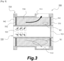
- a hollow fiber membrane module according to such an example of the related art will be described with reference to Fig. 3.
- Fig. 3 is a schematic cross-sectional view of a hollow fiber membrane module according to an embodiment of the related art.
- a hollow fiber membrane module 500 illustrated in the drawing includes a cylindrical outer case 510, an inner case 520 disposed inside the outer case 510, and a plurality of hollow fiber membranes 530 provided in an annular gap between the outer case 510 and the inner case 520.
- the hollow fiber membrane module 500 also includes a pair of sealing fixing portions 541 and 542 and a pair of buffering portions 551 and 552.
- the sealing fixing portions 541 and 542 play a role of sealing the above-described annular gap in a state in which the inside of each of hollows of hollow fiber membranes 530 is open on one end side and the other end side of the outer case 510 and the inner case 520, and fixing the plurality of hollow fiber membranes 530 to the outer case 510 and the inner case 520.
- an outlet portion 511 that makes the annular gap and the outside of the outer case 510 communicate with each other is provided in at least one place in a circumferential direction at a position closer to one end of the outer case 510.
- a portion 512 of the inner peripheral surface of the outer case 510 has an inner diameter larger than that of other portions so as not to be in contact the outer peripheral surface of a bundle constituted of the plurality of hollow fiber membranes 530.
- a partition wall 521 is provided inside the inner case 520, and a plurality of windows 522 that make the hollow portion inside the inner case 520 and the annular gap communicate with each other are provided on the other end side of the partition wall 521.
- a wet gas is supplied to the hollow portion in the inner case 520, and a dry gas is supplied into each of the hollows of the hollow fiber membranes 530 from the sealing fixing portion 541 side.
- the wet gas enters the above-described annular gap through the plurality of windows 522, passes through the outside of the hollow fiber membranes 530, and flows to the outside of the outer case 510 from the outlet portion 511.
- the dry gas flows through the inside of the hollow fiber membrane 530 from the sealing fixing portion 541 on the one end side toward the sealing fixing portion 542 on the other end side.
- moisture in the wet gas moves to the dry gas side, and the dry gas is humidified.
- a plurality of hollow fiber membranes are provided in a single tubular case, and an inlet and an outlet of a wet gas are provided in the case.
- the hollow fiber membranes disposed in the vicinity of the center of the case tend not to contribute much to a membrane separation action.
- all of the plurality of hollow fiber membranes 530 can contribute to a membrane separation action, and thus it is possible to meet the above-described requirements.
- An object of the present invention is to provide a hollow fiber membrane module and a dehumidification/humidification device which are capable of improving a rate of contribution of hollow fiber membranes to a membrane separation action and improving dehumidification/humidification performance.
- the present invention adopts following means in order to solve the above-described problems.
- a hollow fiber membrane module of the present invention is a hollow fiber membrane module including an outer case that has a tubular shape, an inner case that is disposed inside the outer case, a plurality of hollow fiber membranes that are provided in an annular gap between the outer case and the inner case, and a pair of sealing fixing portions that seal the annular gap in a state in which the inside of each of hollows of the hollow fiber membranes is open on one end side and another end side of the outer case and the inner case, and fix the plurality of hollow fiber membranes to the outer case and the inner case, wherein an outlet portion making the annular gap and the outside of the outer case communicate with each other is provided on the one end side of the outer case, and the inner case is provided with a hollow portion that opens to the other end side and also provided with a plurality of windows making the hollow portion and the annular gap communicate with each other, and a plurality of partition walls dividing a space, in which a fluid flows, into a plurality of spaces in a circumferential direction are provided in the
- a fluid that is supplied to the hollow portion and enters the annular gap from the plurality of windows flows through the spaces separated by the plurality of partition walls, and thus a flow rate of the fluid that flows directly to the outlet portion can be reduced.
- a rate of contribution of the hollow fiber membranes to a membrane separation action.
- the plurality of partition walls may be provided integrally with the inner case.
- the plurality of partition walls may be constituted of a plurality of plate-shaped portions radially extending outward from an outer peripheral surface of a tubular portion of the inner case.
- An annular space connecting the plurality of spaces, which are separated by the plurality of partition walls, and the outlet portion may be provided outside the annular gap in a radial direction.
- the inner case may be provided with a widened portion, the width of which in a direction perpendicular to a direction from the one end side to the other end side expands from the one end side to the other end side, and the plurality of windows may be provided in the widened portion.
- a dehumidification/humidification device of the present invention is a dehumidification/humidification device including the hollow fiber membrane module mentioned above, a wet gas supply device that supplies a wet gas to the hollow portion, and a dry gas supply device that supplies a dry gas having a humidity lower than that of the wet gas from the sealing fixing portion on the one end side to the inside of each of the hollows of the plurality of hollow fiber membranes.
- FIG. 1 is a plan view of the hollow fiber membrane module according to the embodiment of the present invention.
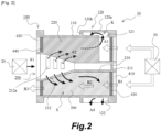
- Fig. 2 is a schematic configuration diagram of the dehumidification/humidification device according to the embodiment of the present invention.
- the hollow fiber membrane module is illustrated as a schematic cross-sectional view. The cross-sectional view corresponds to an AA cross-sectional view of a hollow fiber membrane module in Fig. 1 .
- the dehumidification/humidification device includes a hollow fiber membrane module 10, a wet gas supply device 20, and a dry gas supply device 30.
- the wet gas supply device 20 is configured to supply a wet gas to the outside of hollow fiber membranes 300 provided in the hollow fiber membrane module 10.
- the dry gas supply device 30 is configured to supply a dry gas with a humidity lower than that of the wet gas into each of the hollows of the plurality of hollow fiber membranes 300. Thereby, moisture in the wet gas moves to the dry gas side due to a membrane separation action of the hollow fiber membranes 300.
- the dry gas is humidified, and the wet gas is dehumidified, and thus the dehumidification/humidification device can be used as both a humidification device and a dehumidification device.
- the dehumidification/humidification device according to this embodiment can be suitably used as a humidification device for humidifying an electrolyte membrane provided in a fuel cell.
- wet air generated in the fuel cell is used as the wet gas described above.
- the humidified gas (air) is supplied to the electrolyte membrane provided in the fuel cell, and the electrolyte membrane is maintained in a wet state.
- the material of the hollow fiber membrane 300 for example, polyphenylsulfone (PPSU) or the like having a property of allowing moisture to permeate therethrough by a capillary condensation mechanism by controlling a pore size can be suitably used.
- a hydrophilic hollow fiber membrane can be obtained by spinning using a membrane forming solution obtained by adding PPSU and a hydrophilic polymer (polyvinylporidone) to a solvent when adjusting the membrane forming solution (raw material of the hollow fiber membrane).
- Nafion registered trademark
- the above-describe material has a low elution property and a high strength, it can be suitably used for the dehumidification/humidification device.
- the hollow fiber membrane module 10 includes a tubular outer case 100, an inner case 200 disposed inside the outer case 100, and a plurality of hollow fiber membranes 300 provided in an annular gap S between the outer case 100 and the inner case 200.
- the hollow fiber membrane module 10 includes a pair of sealing fixing portions 410 and 420 and a pair of buffering portions 430 and 440.
- the sealing fixing portions 410 and 420 have a role of sealing the above-described annular gap S with the inside of each of the hollows of the hollow fiber membranes 300 opened on one end side (the right side in Fig. 2 ) and the other end side (the left side in Fig.
- the sealing fixing portions 410 and 420 are obtained by hardening a potting material such as an epoxy resin.
- the pair of buffering portions 430 and 440 are formed of a highly flexible material such as silicon.
- the outer case 100 includes a tubular case main body 110.
- the case main body 110 is constituted by a substantially cylindrical portion, but its shape is not limited. For example, various shapes such as a prismatic shape can be adopted.
- the outer case 100 is provided with a double pipe portion 120 that forms an annular space K outside the annular gap S in the radial direction on one end side.
- the double pipe portion 120 according to this embodiment includes a cylindrical portion 120a having an outer diameter and an inner diameter larger than those of the case main body 110, and a connecting portion 120b that connects the other end side of the cylindrical portion 120a and the case main body 110.
- An outlet portion 122 that makes the annular gap S and the outside of the outer case 100 communicate with each other is provided on one end side of the outer case 100.
- the outer case 100 is provided with a communication portion 121 that makes the annular gap S and one end side of an annular space K communicate with each other, and the annular gap S and the outlet portion 122 are connected to each other via the communication portion 121
- the inner case 200 includes a tubular portion 210.
- a partition wall 211 is provided inside the tubular portion 210.
- the inner case 200 is provided with a hollow portion opening to the other end side.
- the inner case 200 is provided with a widened portion 212 of which the width in a direction perpendicular to a direction from one end side to the other end side expands from one end side to the other end side.
- the inner peripheral surface and the outer peripheral surface of the widened portion 212 according to this embodiment are constituted by tapered surfaces.
- the shapes of the inner peripheral surface and the outer peripheral surface of the widened portion 212 are not limited to the tapered surfaces, and other shapes can be adopted as long as the width in the direction perpendicular to the direction from one end side to the other end side gradually expands.
- a curved surface having a curved cross-sectional shape cut along a plane including a central axis, a surface having a pyramidal surface shape, and the like can also be adopted.
- the widened portion 212 is provided with a plurality of windows 212a that communicate with the hollow portion and the annular gap S.
- the inner diameter and the outer diameter are constant. That is, it is constituted by a cylindrical portion.
- the annular gap S of the hollow fiber membrane module 10 is provided with a plurality of partition walls 220 dividing a space in which a fluid flows into a plurality of spaces in the circumferential direction.
- the plurality of partition walls 220 are provided integrally with the inner case 200. More specifically, the plurality of partition walls 220 are constituted by a plurality of plate-shaped portions radially extending outward from the outer peripheral surface of the tubular portion 210 of the inner case 200.
- the plurality of partition walls do not necessarily need to be provided integrally with the inner case 200.
- the spaces separated by the plurality of partition walls 220 do not need to be completely separated, and adjacent spaces may be partially connected to each other.
- the annular space K provided outside the annular gap S in the radial direction is configured to connect the plurality of spaces separated by the plurality of partition walls 220 and the outlet portion 122. That is, the communication portion 121 is provided to connect at least the plurality of spaces separated by the plurality of partition walls 220 and the annular space K.
- a plurality of communication portions 121 may be provided at intervals in the circumferential direction so as to connect the plurality of spaces separated by the plurality of partition walls 220 and the annular space K, or the communication portion 121 may be provided over the entire circumference.
- the outlet portion 122 may be provided in at least one place in the circumferential direction, and the number of outlet portions 122 can be appropriately set in accordance with the dimensions and the usage environment of the hollow fiber membrane module 10.
- a wet gas is supplied to the hollow portion of the inner case 200 by the wet gas supply device 20.
- a dry gas is supplied into each of the hollows of the plurality of hollow fiber membranes 300 from the sealing fixing portion 410 on one end side by the dry gas supply device 30. This point will be described in more detail.
- a wet gas is supplied from the wet gas supply device 20 to the hollow portion (arrow A1 in Fig. 2 ) and enters the annular gap S through the plurality of windows 212a (arrow A2).
- the wet gas in the annular gap S passes through the outside of the hollow fiber membrane 300, flows from the communication portion 121 to the annular space K (arrow A3), and then flows from the outlet portion 122 to the outside of the outer case 100 (arrow A4).
- a dry gas is supplied into each of the hollows of the plurality of hollow fiber membranes 300 from the sealing fixing portion 410 on one end side by the dry gas supply device 30 (arrow B1), and flows into each of the hollow fiber membranes 300 (arrow B2).
- the dry gas is discharged from the sealing fixing portion 420 on the other end side (arrow B3).
- moisture in the wet gas moves to the dry gas side, the dry gas is humidified, and the wet gas is dehumidified.
- a configuration is adopted in which a wet gas flow from the plurality of windows 212a provided in the inner case 200 to the outlet portion 122 provided in the outer case 100.
- all of the entirety of the plurality of hollow fiber membranes 300 provided in the annular gap S between the inner case 200 and the outer case 100 can contribute to a membrane separation action.
- a fluid that is supplied to the hollow portion of the inner case 200 and enters the annular gap S from the plurality of windows 212a flows through the spaces separated by the plurality of partition walls 220, a flow rate of the fluid that flows directly to the outlet portion 122 can be reduced.
- the plurality of partition walls 220 are provided integrally with the inner case 200, a separate operation of installing the partition walls 220 is not required.
- the plurality of partition walls 220 are constituted by a plurality of plate-shaped portions radially extending outward from the outer peripheral surface of the tubular portion 210 of the inner case 200. Thereby, it is possible to curb a reduction in the volume of the annular gap S and to curb a reduction in the number of hollow fiber membranes 300 filled.
- the annular space K connecting the plurality of spaces, which are separated by the plurality of partition walls 220, and the outlet portion 122 is provided on the outer side of the annular gap S in the radial direction. Thereby, it is not necessary to provide the outlet portion 122 corresponding to each of the spaces separated by the partition walls 220.
- the inner case 200 according to this embodiment is provided with the widened portion 212 of which the width in a direction perpendicular to a direction from one end side to the other end side expands from one end side to the other end side, and the plurality of windows 212a are provided in the widened portion 212.
- a fluid passing through the outside of the hollow fiber membranes 300 and a fluid passing through the inside of the hollows of the hollow fiber membranes 300 can easily flow in opposite directions. Thereby, it is possible to enhance a membrane separation action and to enhance dehumidification/humidification performance.
- the present invention also includes a configuration in which a widened portion is not provided in an inner case, and a plurality of windows are provided in a portion having a constant width.
- the inner case 520 having the plurality of windows 522 as illustrated in Fig. 3 described in the prior art is also applicable to the present invention.
Landscapes
- Chemical & Material Sciences (AREA)
- Chemical Kinetics & Catalysis (AREA)
- Engineering & Computer Science (AREA)
- General Chemical & Material Sciences (AREA)
- Manufacturing & Machinery (AREA)
- Analytical Chemistry (AREA)
- Oil, Petroleum & Natural Gas (AREA)
- Life Sciences & Earth Sciences (AREA)
- Sustainable Development (AREA)
- Sustainable Energy (AREA)
- Electrochemistry (AREA)
- Thermal Sciences (AREA)
- Physics & Mathematics (AREA)
- Separation Using Semi-Permeable Membranes (AREA)
Abstract
Description
- The present invention relates to a hollow fiber membrane module and a dehumidification/humidification device.
- Hollow fiber membrane modules provided in humidification devices for fuel cells are required to have improved humidification performance, reduced pressure loss, and be made small. In order to realize these, it is necessary to increase a rate of contribution of a hollow fiber membrane, which is provided in a case, to a membrane separation action. Consequently, a technique for meeting these requirements by configuring the case of a hollow fiber membrane module to be a double case is known. A hollow fiber membrane module according to such an example of the related art will be described with reference to
Fig. 3. Fig. 3 is a schematic cross-sectional view of a hollow fiber membrane module according to an embodiment of the related art. - A hollow
fiber membrane module 500 illustrated in the drawing includes a cylindricalouter case 510, aninner case 520 disposed inside theouter case 510, and a plurality ofhollow fiber membranes 530 provided in an annular gap between theouter case 510 and theinner case 520. The hollowfiber membrane module 500 also includes a pair of sealingfixing portions buffering portions fixing portions hollow fiber membranes 530 is open on one end side and the other end side of theouter case 510 and theinner case 520, and fixing the plurality ofhollow fiber membranes 530 to theouter case 510 and theinner case 520. - In the
outer case 510, anoutlet portion 511 that makes the annular gap and the outside of theouter case 510 communicate with each other is provided in at least one place in a circumferential direction at a position closer to one end of theouter case 510. In a portion where theportion 511 is not provided, aportion 512 of the inner peripheral surface of theouter case 510 has an inner diameter larger than that of other portions so as not to be in contact the outer peripheral surface of a bundle constituted of the plurality ofhollow fiber membranes 530. - A
partition wall 521 is provided inside theinner case 520, and a plurality ofwindows 522 that make the hollow portion inside theinner case 520 and the annular gap communicate with each other are provided on the other end side of thepartition wall 521. - With respect to the hollow
fiber membrane module 500 configured as described above, a wet gas is supplied to the hollow portion in theinner case 520, and a dry gas is supplied into each of the hollows of thehollow fiber membranes 530 from the sealingfixing portion 541 side. Thereby, as indicated by solid arrows in the drawing, the wet gas enters the above-described annular gap through the plurality ofwindows 522, passes through the outside of thehollow fiber membranes 530, and flows to the outside of theouter case 510 from theoutlet portion 511. The dry gas flows through the inside of thehollow fiber membrane 530 from the sealingfixing portion 541 on the one end side toward the sealingfixing portion 542 on the other end side. Thereby, due to a membrane separation action of thehollow fiber membranes 530, moisture in the wet gas moves to the dry gas side, and the dry gas is humidified. - In the case of a general hollow fiber membrane module, a plurality of hollow fiber membranes are provided in a single tubular case, and an inlet and an outlet of a wet gas are provided in the case. Thus, the hollow fiber membranes disposed in the vicinity of the center of the case tend not to contribute much to a membrane separation action. On the other hand, in the case of the hollow
fiber membrane module 500 according to the above-described example of the related art illustrated inFig. 3 , all of the plurality ofhollow fiber membranes 530 can contribute to a membrane separation action, and thus it is possible to meet the above-described requirements. - However, even in the case of the hollow
fiber membrane module 500 described above, a wet gas tends to flow predominantly through a portion at a shortest distance from thewindow 522 to theoutlet portion 511. For this reason, it has been ascertained that a region away from the outlet portion 511 (near X1 in the drawing) and a region on the one end side and radially inner side (near X2 in the drawing) among the plurality ofhollow fiber membranes 530 do not tend to contribute to a membrane separation action. In this manner, there is still room for improvement. -
- [PTL 1]
Japanese Patent Application Publication No. 2002-147802 - [PTL 2]
Japanese Patent Application Publication No. 2005-265196 - An object of the present invention is to provide a hollow fiber membrane module and a dehumidification/humidification device which are capable of improving a rate of contribution of hollow fiber membranes to a membrane separation action and improving dehumidification/humidification performance.
- The present invention adopts following means in order to solve the above-described problems.
- That is, a hollow fiber membrane module of the present invention is a hollow fiber membrane module including an outer case that has a tubular shape, an inner case that is disposed inside the outer case, a plurality of hollow fiber membranes that are provided in an annular gap between the outer case and the inner case, and a pair of sealing fixing portions that seal the annular gap in a state in which the inside of each of hollows of the hollow fiber membranes is open on one end side and another end side of the outer case and the inner case, and fix the plurality of hollow fiber membranes to the outer case and the inner case, wherein an outlet portion making the annular gap and the outside of the outer case communicate with each other is provided on the one end side of the outer case, and the inner case is provided with a hollow portion that opens to the other end side and also provided with a plurality of windows making the hollow portion and the annular gap communicate with each other, and a plurality of partition walls dividing a space, in which a fluid flows, into a plurality of spaces in a circumferential direction are provided in the annular gap.
- According to the present invention, a fluid that is supplied to the hollow portion and enters the annular gap from the plurality of windows flows through the spaces separated by the plurality of partition walls, and thus a flow rate of the fluid that flows directly to the outlet portion can be reduced. Thus, it is possible to improve a rate of contribution of the hollow fiber membranes to a membrane separation action.
- The plurality of partition walls may be provided integrally with the inner case.
- Thereby, a separate operation of installing the partition walls is not required
- The plurality of partition walls may be constituted of a plurality of plate-shaped portions radially extending outward from an outer peripheral surface of a tubular portion of the inner case.
- Thereby, it is possible to curb reduction in the volume of the annular gap and to curb reduction in the number of hollow fiber membranes that can be filled thereinto.
- An annular space connecting the plurality of spaces, which are separated by the plurality of partition walls, and the outlet portion may be provided outside the annular gap in a radial direction.
- Thereby, it is not necessary to provide the outlet portion corresponding to each of the spaces separated by the partition walls.
- The inner case may be provided with a widened portion, the width of which in a direction perpendicular to a direction from the one end side to the other end side expands from the one end side to the other end side, and the plurality of windows may be provided in the widened portion.
- By adopting such a configuration, in the vicinity of the windows, a fluid passing through the outside of the hollow fiber membranes and a fluid passing through the inside of the hollows of the hollow fiber membranes can easily flow in opposite directions.
- A dehumidification/humidification device of the present invention is a dehumidification/humidification device including the hollow fiber membrane module mentioned above, a wet gas supply device that supplies a wet gas to the hollow portion, and a dry gas supply device that supplies a dry gas having a humidity lower than that of the wet gas from the sealing fixing portion on the one end side to the inside of each of the hollows of the plurality of hollow fiber membranes.
- The above-described configurations can be adopted in combination as far as possible.
- As described above, according to the present invention, it is possible to improve a rate of contribution of hollow fiber membranes to a membrane separation action and to improve dehumidification/humidification performance.
-
- [
Fig. 1 ]
Fig. 1 is a plan view of a hollow fiber membrane module according to an embodiment of the present invention. - [
Fig. 2 ]
Fig. 2 is a schematic configuration diagram of a dehumidification/humidification device according to the embodiment of the present invention. - [
Fig. 3 ]
Fig. 3 is a schematic cross-sectional view of a hollow fiber membrane module according to an embodiment of the related art. - Modes for carrying out the present invention will be described in detail below based on embodiments with reference to the drawings. However, unless otherwise specified, dimensions, materials, shapes, and relative arrangements of components described in the embodiments are not intended to limit the scope of the present invention.
- A hollow fiber membrane module and a dehumidification/humidification device according to an embodiment of the present invention will be described with reference to
Figs. 1 and2 .Fig. 1 is a plan view of the hollow fiber membrane module according to the embodiment of the present invention.Fig. 2 is a schematic configuration diagram of the dehumidification/humidification device according to the embodiment of the present invention. InFig. 2 , the hollow fiber membrane module is illustrated as a schematic cross-sectional view. The cross-sectional view corresponds to an AA cross-sectional view of a hollow fiber membrane module inFig. 1 . - The dehumidification/humidification device according to this embodiment includes a hollow
fiber membrane module 10, a wetgas supply device 20, and a drygas supply device 30. The wetgas supply device 20 is configured to supply a wet gas to the outside ofhollow fiber membranes 300 provided in the hollowfiber membrane module 10. The drygas supply device 30 is configured to supply a dry gas with a humidity lower than that of the wet gas into each of the hollows of the plurality ofhollow fiber membranes 300. Thereby, moisture in the wet gas moves to the dry gas side due to a membrane separation action of thehollow fiber membranes 300. Thus, the dry gas is humidified, and the wet gas is dehumidified, and thus the dehumidification/humidification device can be used as both a humidification device and a dehumidification device. The dehumidification/humidification device according to this embodiment can be suitably used as a humidification device for humidifying an electrolyte membrane provided in a fuel cell. In this case, wet air generated in the fuel cell is used as the wet gas described above. The humidified gas (air) is supplied to the electrolyte membrane provided in the fuel cell, and the electrolyte membrane is maintained in a wet state. Here, as the material of thehollow fiber membrane 300, for example, polyphenylsulfone (PPSU) or the like having a property of allowing moisture to permeate therethrough by a capillary condensation mechanism by controlling a pore size can be suitably used. A hydrophilic hollow fiber membrane can be obtained by spinning using a membrane forming solution obtained by adding PPSU and a hydrophilic polymer (polyvinylporidone) to a solvent when adjusting the membrane forming solution (raw material of the hollow fiber membrane). Nafion (registered trademark), which is a hydrophilic material having a property of allowing moisture to permeate therethrough by dissolution and diffusion, can also be used. Since the above-describe material has a low elution property and a high strength, it can be suitably used for the dehumidification/humidification device. - The hollow
fiber membrane module 10 according to this embodiment will be described in more detail. The hollowfiber membrane module 10 includes a tubularouter case 100, aninner case 200 disposed inside theouter case 100, and a plurality ofhollow fiber membranes 300 provided in an annular gap S between theouter case 100 and theinner case 200. The hollowfiber membrane module 10 includes a pair of sealing fixingportions portions sealing fixing portions hollow fiber membranes 300 opened on one end side (the right side inFig. 2 ) and the other end side (the left side inFig. 2 ) of theouter case 100 and theinner case 200, and fixing the plurality ofhollow fiber membranes 300 to theouter case 100 and theinner case 200. Thesealing fixing portions portions buffering portions hollow fiber membranes 300 in the vicinity of thesealing fixing portions hollow fiber membranes 300 in the vicinity of interfaces with thesealing fixing portions fiber membrane module 10 inFig. 2 will be referred to as "one end side" and the left side will be referred to as "the other end side". - The
outer case 100 includes a tubular casemain body 110. In this embodiment, the casemain body 110 is constituted by a substantially cylindrical portion, but its shape is not limited. For example, various shapes such as a prismatic shape can be adopted. Theouter case 100 is provided with adouble pipe portion 120 that forms an annular space K outside the annular gap S in the radial direction on one end side. Thedouble pipe portion 120 according to this embodiment includes acylindrical portion 120a having an outer diameter and an inner diameter larger than those of the casemain body 110, and a connectingportion 120b that connects the other end side of thecylindrical portion 120a and the casemain body 110. Anoutlet portion 122 that makes the annular gap S and the outside of theouter case 100 communicate with each other is provided on one end side of theouter case 100. Theouter case 100 is provided with acommunication portion 121 that makes the annular gap S and one end side of an annular space K communicate with each other, and the annular gap S and theoutlet portion 122 are connected to each other via thecommunication portion 121. - The
inner case 200 includes atubular portion 210. Apartition wall 211 is provided inside thetubular portion 210. Thereby, theinner case 200 is provided with a hollow portion opening to the other end side. Theinner case 200 is provided with a widenedportion 212 of which the width in a direction perpendicular to a direction from one end side to the other end side expands from one end side to the other end side. The inner peripheral surface and the outer peripheral surface of the widenedportion 212 according to this embodiment are constituted by tapered surfaces. The shapes of the inner peripheral surface and the outer peripheral surface of the widenedportion 212 are not limited to the tapered surfaces, and other shapes can be adopted as long as the width in the direction perpendicular to the direction from one end side to the other end side gradually expands. For example, a curved surface having a curved cross-sectional shape cut along a plane including a central axis, a surface having a pyramidal surface shape, and the like can also be adopted. - In the
inner case 200, the widenedportion 212 is provided with a plurality ofwindows 212a that communicate with the hollow portion and the annular gap S. On one end side of the widenedportion 212 in theinner case 200, the inner diameter and the outer diameter are constant. That is, it is constituted by a cylindrical portion. - The annular gap S of the hollow
fiber membrane module 10 according to this embodiment is provided with a plurality ofpartition walls 220 dividing a space in which a fluid flows into a plurality of spaces in the circumferential direction. In this embodiment, the plurality ofpartition walls 220 are provided integrally with theinner case 200. More specifically, the plurality ofpartition walls 220 are constituted by a plurality of plate-shaped portions radially extending outward from the outer peripheral surface of thetubular portion 210 of theinner case 200. With a configuration in which the space in which the fluid flows is divided into a plurality of spaces in the circumferential direction, the plurality of partition walls do not necessarily need to be provided integrally with theinner case 200. The spaces separated by the plurality ofpartition walls 220 do not need to be completely separated, and adjacent spaces may be partially connected to each other. - Here, the annular space K provided outside the annular gap S in the radial direction is configured to connect the plurality of spaces separated by the plurality of
partition walls 220 and theoutlet portion 122. That is, thecommunication portion 121 is provided to connect at least the plurality of spaces separated by the plurality ofpartition walls 220 and the annular space K. A plurality ofcommunication portions 121 may be provided at intervals in the circumferential direction so as to connect the plurality of spaces separated by the plurality ofpartition walls 220 and the annular space K, or thecommunication portion 121 may be provided over the entire circumference. Theoutlet portion 122 may be provided in at least one place in the circumferential direction, and the number ofoutlet portions 122 can be appropriately set in accordance with the dimensions and the usage environment of the hollowfiber membrane module 10. - With respect to the hollow
fiber membrane module 10 configured as described above, a wet gas is supplied to the hollow portion of theinner case 200 by the wetgas supply device 20. A dry gas is supplied into each of the hollows of the plurality ofhollow fiber membranes 300 from thesealing fixing portion 410 on one end side by the drygas supply device 30. This point will be described in more detail. - A wet gas is supplied from the wet
gas supply device 20 to the hollow portion (arrow A1 inFig. 2 ) and enters the annular gap S through the plurality ofwindows 212a (arrow A2). The wet gas in the annular gap S passes through the outside of thehollow fiber membrane 300, flows from thecommunication portion 121 to the annular space K (arrow A3), and then flows from theoutlet portion 122 to the outside of the outer case 100 (arrow A4). A dry gas is supplied into each of the hollows of the plurality ofhollow fiber membranes 300 from thesealing fixing portion 410 on one end side by the dry gas supply device 30 (arrow B1), and flows into each of the hollow fiber membranes 300 (arrow B2). Thereafter, the dry gas is discharged from thesealing fixing portion 420 on the other end side (arrow B3). In the process described above, due to a membrane separation action of thehollow fiber membranes 300, moisture in the wet gas moves to the dry gas side, the dry gas is humidified, and the wet gas is dehumidified. - According to this embodiment, a configuration is adopted in which a wet gas flow from the plurality of
windows 212a provided in theinner case 200 to theoutlet portion 122 provided in theouter case 100. For this reason, all of the entirety of the plurality ofhollow fiber membranes 300 provided in the annular gap S between theinner case 200 and theouter case 100 can contribute to a membrane separation action. Since a fluid that is supplied to the hollow portion of theinner case 200 and enters the annular gap S from the plurality ofwindows 212a flows through the spaces separated by the plurality ofpartition walls 220, a flow rate of the fluid that flows directly to theoutlet portion 122 can be reduced. Thus, it is possible to improve a rate of contribution of thehollow fiber membranes 300 to a membrane separation action. Thereby, it is possible to achieve an improvement in dehumidification/humidification performance. - In this embodiment, since the plurality of
partition walls 220 are provided integrally with theinner case 200, a separate operation of installing thepartition walls 220 is not required. The plurality ofpartition walls 220 are constituted by a plurality of plate-shaped portions radially extending outward from the outer peripheral surface of thetubular portion 210 of theinner case 200. Thereby, it is possible to curb a reduction in the volume of the annular gap S and to curb a reduction in the number ofhollow fiber membranes 300 filled. - In this embodiment, the annular space K connecting the plurality of spaces, which are separated by the plurality of
partition walls 220, and theoutlet portion 122 is provided on the outer side of the annular gap S in the radial direction. Thereby, it is not necessary to provide theoutlet portion 122 corresponding to each of the spaces separated by thepartition walls 220. - The
inner case 200 according to this embodiment is provided with the widenedportion 212 of which the width in a direction perpendicular to a direction from one end side to the other end side expands from one end side to the other end side, and the plurality ofwindows 212a are provided in the widenedportion 212. Thus, in the vicinity of thewindows 212a, a fluid passing through the outside of thehollow fiber membranes 300 and a fluid passing through the inside of the hollows of thehollow fiber membranes 300 can easily flow in opposite directions. Thereby, it is possible to enhance a membrane separation action and to enhance dehumidification/humidification performance. - In the above-described embodiment, a configuration in a case where the
inner case 200 is provided with the widenedportion 212, and the widenedportion 212 is provided with the plurality ofwindows 212a has been described. However, the present invention also includes a configuration in which a widened portion is not provided in an inner case, and a plurality of windows are provided in a portion having a constant width. For example, theinner case 520 having the plurality ofwindows 522 as illustrated inFig. 3 described in the prior art is also applicable to the present invention. -
- 10
- Hollow fiber membrane module
- 20
- Wet gas supply device
- 30
- Dry gas supply device
- 100
- Outer case
- 110
- Case main body
- 120
- Double pipe portion
- 120a
- Cylindrical portion
- 120b
- Connecting portion
- 121
- Communication portion
- 122
- Outlet portion
- 200
- Inner case
- 210
- Tubular portion
- 211
- Partition wall
- 212
- Widened portion
- 212a
- Window
- 220
- Partition wall
- 300
- Hollow fiber membrane
- 410, 420
- Sealing fixing portion
- 430, 440
- Buffering portion
- K
- Annular space
- S
- Annular gap
Claims (6)
- A hollow fiber membrane module comprising:an outer case that has a tubular shape;an inner case that is disposed inside the outer case;a plurality of hollow fiber membranes that are provided in an annular gap between the outer case and the inner case; anda pair of sealing fixing portions that seal the annular gap in a state in which the inside of each of hollows of the hollow fiber membranes is open on one end side and another end side of the outer case and the inner case, and fix the plurality of hollow fiber membranes to the outer case and the inner case, whereinan outlet portion making the annular gap and the outside of the outer case communicate with each other is provided on the one end side of the outer case, and the inner case is provided with a hollow portion that opens to the other end side and also provided with a plurality of windows making the hollow portion and the annular gap communicate with each other, anda plurality of partition walls dividing a space, in which a fluid flows, into a plurality of spaces in a circumferential direction are provided in the annular gap.
- The hollow fiber membrane module according to claim 1, wherein the plurality of partition walls are provided integrally with the inner case.
- The hollow fiber membrane module according to claim 2, wherein the plurality of partition walls are constituted of a plurality of plate-shaped portions radially extending outward from an outer peripheral surface of a tubular portion of the inner case.
- The hollow fiber membrane module according to claim 1, 2, or 3, wherein an annular space connecting the plurality of spaces, which are separated by the plurality of partition walls, and the outlet portion is provided outside the annular gap in a radial direction.
- The hollow fiber membrane module according to any one of claims 1 to 4, wherein the inner case is provided with a widened portion, the width of which in a direction perpendicular to a direction from the one end side to the other end side expands from the one end side to the other end side, and the plurality of windows are provided in the widened portion.
- A dehumidification/humidification device comprising:the hollow fiber membrane module according to any one of claims 1 to 5;a wet gas supply device that supplies a wet gas to the hollow portion; anda dry gas supply device that supplies a dry gas having a humidity lower than that of the wet gas from the sealing fixing portion on the one end side to the inside of each of the hollows of the plurality of hollow fiber membranes.
Applications Claiming Priority (2)
| Application Number | Priority Date | Filing Date | Title |
|---|---|---|---|
| JP2021092811 | 2021-06-02 | ||
| PCT/JP2022/020488 WO2022255085A1 (en) | 2021-06-02 | 2022-05-17 | Hollow fiber membrane module and dehumidification/humidification device |
Publications (2)
| Publication Number | Publication Date |
|---|---|
| EP4349465A1 true EP4349465A1 (en) | 2024-04-10 |
| EP4349465A4 EP4349465A4 (en) | 2025-05-21 |
Family
ID=84323235
Family Applications (1)
| Application Number | Title | Priority Date | Filing Date |
|---|---|---|---|
| EP22815837.4A Pending EP4349465A4 (en) | 2021-06-02 | 2022-05-17 | Hollow fiber membrane module and dehumidification/humidification device |
Country Status (7)
| Country | Link |
|---|---|
| US (1) | US20240173675A1 (en) |
| EP (1) | EP4349465A4 (en) |
| JP (1) | JP7685050B2 (en) |
| KR (1) | KR20230145389A (en) |
| CN (1) | CN117042866A (en) |
| CA (1) | CA3214330A1 (en) |
| WO (1) | WO2022255085A1 (en) |
Families Citing this family (2)
| Publication number | Priority date | Publication date | Assignee | Title |
|---|---|---|---|---|
| KR20230145399A (en) * | 2021-06-02 | 2023-10-17 | 엔오케이 가부시키가이샤 | Hollow membrane module and dehumidification device |
| EP4349462A4 (en) * | 2021-06-02 | 2025-05-21 | NOK Corporation | Hollow fiber membrane module |
Family Cites Families (16)
| Publication number | Priority date | Publication date | Assignee | Title |
|---|---|---|---|---|
| JPH0779954B2 (en) * | 1988-08-25 | 1995-08-30 | 宇部興産株式会社 | Gas separation membrane module |
| EP0519132A1 (en) * | 1989-10-18 | 1992-12-23 | Exxon Research And Engineering Company | Hollow fiber module |
| JP3927344B2 (en) * | 2000-01-19 | 2007-06-06 | 本田技研工業株式会社 | Humidifier |
| JP4610715B2 (en) | 2000-11-06 | 2011-01-12 | Nok株式会社 | Humidifier |
| JP2002303435A (en) * | 2001-03-30 | 2002-10-18 | Honda Motor Co Ltd | Humidification module |
| US20070095741A1 (en) * | 2003-10-31 | 2007-05-03 | Berends Hendrik Johan F | Filter module |
| JP4516333B2 (en) | 2004-03-16 | 2010-08-04 | 本田技研工業株式会社 | humidifier |
| JP4644136B2 (en) | 2006-02-10 | 2011-03-02 | 本田技研工業株式会社 | Humidifier |
| JP2007216175A (en) | 2006-02-17 | 2007-08-30 | Nissan Motor Co Ltd | Hollow fiber membrane module and manufacturing method thereof |
| US9048469B2 (en) | 2009-07-24 | 2015-06-02 | Honda Motor Co., Ltd | Hollow-fiber membrane module for moisture exchange |
| JP5481204B2 (en) | 2010-01-07 | 2014-04-23 | 本田技研工業株式会社 | Humidification module |
| JP5710127B2 (en) * | 2010-01-14 | 2015-04-30 | 本田技研工業株式会社 | Hollow fiber membrane module for moisture exchange |
| KR101251256B1 (en) * | 2011-03-09 | 2013-04-10 | 기아자동차주식회사 | Humidification device for fuel cell |
| JP6252281B2 (en) * | 2014-03-20 | 2017-12-27 | Nok株式会社 | Method for producing hollow fiber membrane module |
| JP2015181985A (en) * | 2014-03-20 | 2015-10-22 | Nok株式会社 | hollow fiber membrane module |
| KR102252042B1 (en) * | 2017-09-26 | 2021-05-13 | 코오롱인더스트리 주식회사 | Assembly type cartridge block and hollow fiber membrane module comprising thereof |
-
2022
- 2022-05-17 CN CN202280021940.1A patent/CN117042866A/en active Pending
- 2022-05-17 KR KR1020237030479A patent/KR20230145389A/en active Pending
- 2022-05-17 WO PCT/JP2022/020488 patent/WO2022255085A1/en not_active Ceased
- 2022-05-17 JP JP2023525707A patent/JP7685050B2/en active Active
- 2022-05-17 US US18/285,150 patent/US20240173675A1/en active Pending
- 2022-05-17 EP EP22815837.4A patent/EP4349465A4/en active Pending
- 2022-05-17 CA CA3214330A patent/CA3214330A1/en active Pending
Also Published As
| Publication number | Publication date |
|---|---|
| JPWO2022255085A1 (en) | 2022-12-08 |
| JP7685050B2 (en) | 2025-05-28 |
| US20240173675A1 (en) | 2024-05-30 |
| CA3214330A1 (en) | 2022-12-08 |
| EP4349465A4 (en) | 2025-05-21 |
| KR20230145389A (en) | 2023-10-17 |
| WO2022255085A1 (en) | 2022-12-08 |
| CN117042866A (en) | 2023-11-10 |
Similar Documents
| Publication | Publication Date | Title |
|---|---|---|
| US7624971B2 (en) | Humidifying system | |
| EP4349466A1 (en) | Hollow fiber membrane module | |
| EP4349467A1 (en) | Hollow fiber membrane module and dehumidification and humidification device | |
| US20240173675A1 (en) | Hollow fiber membrane module and dehumidification/humidification device | |
| EP4349464A1 (en) | Hollow fiber membrane module and dehumidifier/humidifier | |
| CN111683730B (en) | Hollow Fiber Membrane Module | |
| US20240335794A1 (en) | Hollow fiber membrane module | |
| JP2019058896A (en) | Hollow fiber membrane module | |
| JP7724869B2 (en) | Hollow fiber membrane module | |
| CA3214464C (en) | Hollow fiber membrane module | |
| EP4725590A1 (en) | Hollow fiber membrane module | |
| US20240252989A1 (en) | Hollow fiber membrane module | |
| EP4670828A1 (en) | HOLLOW FIBER MEMBRANE MODULE |
Legal Events
| Date | Code | Title | Description |
|---|---|---|---|
| STAA | Information on the status of an ep patent application or granted ep patent |
Free format text: STATUS: THE INTERNATIONAL PUBLICATION HAS BEEN MADE |
|
| PUAI | Public reference made under article 153(3) epc to a published international application that has entered the european phase |
Free format text: ORIGINAL CODE: 0009012 |
|
| STAA | Information on the status of an ep patent application or granted ep patent |
Free format text: STATUS: REQUEST FOR EXAMINATION WAS MADE |
|
| 17P | Request for examination filed |
Effective date: 20230926 |
|
| AK | Designated contracting states |
Kind code of ref document: A1 Designated state(s): AL AT BE BG CH CY CZ DE DK EE ES FI FR GB GR HR HU IE IS IT LI LT LU LV MC MK MT NL NO PL PT RO RS SE SI SK SM TR |
|
| DAV | Request for validation of the european patent (deleted) | ||
| DAX | Request for extension of the european patent (deleted) | ||
| A4 | Supplementary search report drawn up and despatched |
Effective date: 20250417 |
|
| RIC1 | Information provided on ipc code assigned before grant |
Ipc: H01M 8/04119 20160101ALI20250411BHEP Ipc: B01D 71/68 20060101ALI20250411BHEP Ipc: B01D 53/26 20060101ALI20250411BHEP Ipc: H01M 8/04 20160101ALI20250411BHEP Ipc: B01D 53/22 20060101ALI20250411BHEP Ipc: B01D 63/02 20060101AFI20250411BHEP |