EP4347314B1 - Camera monitoring system display including parallax manipulation - Google Patents
Camera monitoring system display including parallax manipulation Download PDFInfo
- Publication number
- EP4347314B1 EP4347314B1 EP22732822.6A EP22732822A EP4347314B1 EP 4347314 B1 EP4347314 B1 EP 4347314B1 EP 22732822 A EP22732822 A EP 22732822A EP 4347314 B1 EP4347314 B1 EP 4347314B1
- Authority
- EP
- European Patent Office
- Prior art keywords
- image
- relative
- objects
- vehicle operator
- cms
- Prior art date
- Legal status (The legal status is an assumption and is not a legal conclusion. Google has not performed a legal analysis and makes no representation as to the accuracy of the status listed.)
- Active
Links
Images

Classifications
-
- B—PERFORMING OPERATIONS; TRANSPORTING
- B60—VEHICLES IN GENERAL
- B60R—VEHICLES, VEHICLE FITTINGS, OR VEHICLE PARTS, NOT OTHERWISE PROVIDED FOR
- B60R1/00—Optical viewing arrangements; Real-time viewing arrangements for drivers or passengers using optical image capturing systems, e.g. cameras or video systems specially adapted for use in or on vehicles
- B60R1/20—Real-time viewing arrangements for drivers or passengers using optical image capturing systems, e.g. cameras or video systems specially adapted for use in or on vehicles
- B60R1/22—Real-time viewing arrangements for drivers or passengers using optical image capturing systems, e.g. cameras or video systems specially adapted for use in or on vehicles for viewing an area outside the vehicle, e.g. the exterior of the vehicle
- B60R1/28—Real-time viewing arrangements for drivers or passengers using optical image capturing systems, e.g. cameras or video systems specially adapted for use in or on vehicles for viewing an area outside the vehicle, e.g. the exterior of the vehicle with an adjustable field of view
-
- B—PERFORMING OPERATIONS; TRANSPORTING
- B60—VEHICLES IN GENERAL
- B60R—VEHICLES, VEHICLE FITTINGS, OR VEHICLE PARTS, NOT OTHERWISE PROVIDED FOR
- B60R1/00—Optical viewing arrangements; Real-time viewing arrangements for drivers or passengers using optical image capturing systems, e.g. cameras or video systems specially adapted for use in or on vehicles
- B60R1/20—Real-time viewing arrangements for drivers or passengers using optical image capturing systems, e.g. cameras or video systems specially adapted for use in or on vehicles
- B60R1/22—Real-time viewing arrangements for drivers or passengers using optical image capturing systems, e.g. cameras or video systems specially adapted for use in or on vehicles for viewing an area outside the vehicle, e.g. the exterior of the vehicle
- B60R1/23—Real-time viewing arrangements for drivers or passengers using optical image capturing systems, e.g. cameras or video systems specially adapted for use in or on vehicles for viewing an area outside the vehicle, e.g. the exterior of the vehicle with a predetermined field of view
- B60R1/25—Real-time viewing arrangements for drivers or passengers using optical image capturing systems, e.g. cameras or video systems specially adapted for use in or on vehicles for viewing an area outside the vehicle, e.g. the exterior of the vehicle with a predetermined field of view to the sides of the vehicle
-
- B—PERFORMING OPERATIONS; TRANSPORTING
- B60—VEHICLES IN GENERAL
- B60R—VEHICLES, VEHICLE FITTINGS, OR VEHICLE PARTS, NOT OTHERWISE PROVIDED FOR
- B60R11/00—Arrangements for holding or mounting articles, not otherwise provided for
- B60R11/02—Arrangements for holding or mounting articles, not otherwise provided for for radio sets, television sets, telephones, or the like; Arrangement of controls thereof
- B60R11/0229—Arrangements for holding or mounting articles, not otherwise provided for for radio sets, television sets, telephones, or the like; Arrangement of controls thereof for displays, e.g. cathodic tubes
-
- B—PERFORMING OPERATIONS; TRANSPORTING
- B60—VEHICLES IN GENERAL
- B60R—VEHICLES, VEHICLE FITTINGS, OR VEHICLE PARTS, NOT OTHERWISE PROVIDED FOR
- B60R2300/00—Details of viewing arrangements using cameras and displays, specially adapted for use in a vehicle
- B60R2300/10—Details of viewing arrangements using cameras and displays, specially adapted for use in a vehicle characterised by the type of camera system used
-
- B—PERFORMING OPERATIONS; TRANSPORTING
- B60—VEHICLES IN GENERAL
- B60R—VEHICLES, VEHICLE FITTINGS, OR VEHICLE PARTS, NOT OTHERWISE PROVIDED FOR
- B60R2300/00—Details of viewing arrangements using cameras and displays, specially adapted for use in a vehicle
- B60R2300/30—Details of viewing arrangements using cameras and displays, specially adapted for use in a vehicle characterised by the type of image processing
- B60R2300/306—Details of viewing arrangements using cameras and displays, specially adapted for use in a vehicle characterised by the type of image processing using a re-scaling of images
-
- B—PERFORMING OPERATIONS; TRANSPORTING
- B60—VEHICLES IN GENERAL
- B60R—VEHICLES, VEHICLE FITTINGS, OR VEHICLE PARTS, NOT OTHERWISE PROVIDED FOR
- B60R2300/00—Details of viewing arrangements using cameras and displays, specially adapted for use in a vehicle
- B60R2300/50—Details of viewing arrangements using cameras and displays, specially adapted for use in a vehicle characterised by the display information being shared, e.g. external display, data transfer to other traffic participants or centralised traffic controller
-
- B—PERFORMING OPERATIONS; TRANSPORTING
- B60—VEHICLES IN GENERAL
- B60R—VEHICLES, VEHICLE FITTINGS, OR VEHICLE PARTS, NOT OTHERWISE PROVIDED FOR
- B60R2300/00—Details of viewing arrangements using cameras and displays, specially adapted for use in a vehicle
- B60R2300/80—Details of viewing arrangements using cameras and displays, specially adapted for use in a vehicle characterised by the intended use of the viewing arrangement
- B60R2300/8046—Details of viewing arrangements using cameras and displays, specially adapted for use in a vehicle characterised by the intended use of the viewing arrangement for replacing a rear-view mirror system
Definitions
- CMS camera monitoring system
- Existing CMS utilize a set of displays that replicate the views provided by one or more conventional mirrors as well as any additional views.
- the views provided by the CMS are flat two-dimensional views. Due to the nature of camera imaging, the flat two-dimensional views do not shift or adjust based on the position of the vehicle operator's head or the direction of the operator's gaze as a conventional mirror would.
- WO2014204794A1 that corresponds to the preamble of claims 1 and 8, discloses a vision system of a vehicle including a camera having a lens and a two dimensional imaging array sensor.
- the camera is disposed at a side of a body of a vehicle and has a field of view exterior of the vehicle and at least rearward of the vehicle.
- a video display is disposed in the vehicle and is viewable by a driver of the vehicle when the driver is normally operating the vehicle.
- DE102018100194B3 discloses a mirror replacement system for a motor vehicle, with a processor unit, an optical sensor unit, and a screen, which is set up to display at least part of image and/or video data generated.
- the mirror replacement system comprises a viewing direction sensor which is set up to detect the direction in which the vehicle driver is looking at the screen or the position of the vehicle driver's head.
- An aspect relates to a mirror replacement system for a commercial vehicle including a camera monitoring system (CMS) including at least one camera, and at least one display configured to display images from the at least one camera to a vehicle operator, a driver monitoring system (DMS) including at least one interior camera, the at least one interior camera having a field of view including at least a portion of the vehicle operator's head, the DMS being configured to identify at least one of a head position and orientation of the vehicle operator, a pose of the vehicle operator, and a gaze direction of the vehicle operator, and a controller configured to: detect a shift in at least one of the vehicle operator's head position, the vehicle operator's pose and the vehicle operator's gaze; determine a rotation of the vehicle operator relative to the at least one display based on the detected shift; and digitally manipulate at least one image from the CMS by simulating at least one parallax effect corresponding to the determined rotation; wherein the digital manipulation includes an adjustment of a relative position of objects within the at least one image relative to an anchor point; and wherein
- the at least one display includes a first display disposed at or near a first A-pillar and a second display disposed at or near a second A-pillar, each of the first display and the second display configured to display a corresponding rear view of the vehicle.
- the corresponding rear view of the vehicle includes at least one of a Class II and a Class IV view.
- the digital manipulation further includes an adjustment of at least one of the relative skew and the relative size of the objects in each display in response to determining the rotation of the vehicle operator relative to the at least one display.
- the digital manipulation further includes an adjustment of the relative size of objects in the image and the relative skew of objects in the image in response to the change in the rotation of the vehicle operator relative to the at least one display.
- the controller further includes an object identification module configured to distinguish objects within an image feed.
- the at least one interior camera includes at least two interior cameras.
- Another aspect relates to a method for operating a camera monitoring system including detecting a shift in at least one of a vehicle operator's head position, the vehicle operator's pose and the vehicle operator's gaze, determining a rotation of the vehicle operator relative to a display based on the detected shift, and digitally manipulating at least one camera monitoring system (CMS) image by simulating at least one parallax effect corresponding to the determined rotation; wherein said digitally manipulating the at least one CMS image comprises adjusting a relative position of objects within the at least one CMS image relative to an anchor point; wherein the anchor point is at least one object in the image, is a focal point of the vehicle operator, or is a position midway between at least two identified objects in the image.
- CMS camera monitoring system
- digitally manipulating the at least one CMS image comprises adjusting at least one of a relative size of objects within the CMS image and a relative skew of the objects within the CMS image.
- digitally manipulating the at least one CMS image comprises adjusting the relative position of the objects within the CMS image and a relative skew of the objects within the CMS image.
- any of the above described methods for operating a camera monitoring system digitally manipulating by adjusting at least one of a relative size of objects within the CMS image and a relative skew of the objects within the CMS image includes adjusting the image relative to the anchor point.
- the anchor point is at least one object in the image.
- the anchor point is a focal point of the vehicle operator.
- the anchor point is position midway between at least two identified objects.
- detecting the rotation of the vehicle operator relative to the display includes monitoring each of the vehicle operator's head position, pose, and gaze position using a driver monitoring system.
- the CMS image is a 2D image.
- the CMS image is a 3D image.
- the method is continuously iterated and the at least one CMS image includes a video feed.
- the video feed includes a first camera corresponding to a first mirror position and a second camera corresponding to a second mirror position.
- any of the above described methods for operating a camera monitoring system simulating at least one parallax effect comprises magnifying an actual parallax effect and simulating the magnified parallax effect.
- FIG. 1A and 1B A schematic view of a commercial vehicle 10 is illustrated in Figures 1A and 1B .
- the vehicle 10 includes a vehicle cab or tractor 12 for pulling a trailer 14. Although a commercial truck is contemplated in this disclosure, the invention may also be applied to other types of vehicles.
- the vehicle 10 incorporates a camera monitoring system (CMS) 15 ( Fig. 2 ) that has driver and passenger side camera arms 16a, 16b mounted to the outside of the vehicle cab 12.
- the camera arms 16a, 16b may include conventional mirrors integrated with them as well, although the CMS 15 can be used to entirely replace mirrors.
- each side can include multiple camera arms, each arm housing one or more cameras and/or mirrors.
- Each of the camera arms 16a, 16b includes a base that is secured to, for example, the cab 12.
- a pivoting arm is supported by the base and may articulate relative thereto.
- At least one rearward facing camera 20a, 20b is arranged respectively within camera arms.
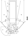
- the exterior cameras 20a, 20b respectively provide an exterior field of view FOV EX1 , FOV EX2 that each include at least one of the Class II and Class IV views ( Fig. 1B ), which are legal prescribed views in the commercial trucking industry. Multiple cameras also may be used in each camera arm 16a, 16b to provide these views, if desired.
- Each arm 16a, 16b may also provide a housing that encloses electronics that are configured to provide various features of the CMS 15.
- First and second video displays 18a, 18b are arranged on each of the driver and passenger sides within the vehicle cab 12 on or near the A-pillars 19a, 19b to display Class II and Class IV views on the respective sides of the vehicle 10.
- the views provide rear facing side views along the vehicle 10 that are captured by the exterior cameras 20a, 20b.
- a camera housing 16c and camera 20c may be arranged at or near the front of the vehicle 10 to provide those views ( Fig. 1B ).
- a third display 18c arranged within the cab 12 near the top center of the windshield can be used to display the Class V and Class VI views, which are toward the front of the vehicle 10, to the driver.
- camera housings can be disposed at the sides and rear of the vehicle 10 to provide fields of view including some or all of the class VIII zones around the vehicle 10.
- the third display 18c can include one or more frames displaying the class VIII views.
- additional displays can be added near the first, second and third displays 18a, 18b, 18c and provide a display dedicated to providing a class VIII view.
- the additional displays can be included in alternative locations throughout the vehicle 10 cabin allowing the user a good view
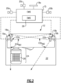
- the displays 18a, 18b, 18c face a driver region 24 within the cabin 22 where an operator is seated on a driver seat 26. It may be desirable to incorporate a driver monitoring system (DMS) 29 into the CMS 15 to evaluate driver activity in the driver region 24 and to identify driver parameters that may be indicative of distracted driving or of any other driver characteristic being monitored.
- DMS 29 is illustrated in Figure 2 .
- First and second interior cameras 28a, 28b are arranged in the vehicle cabin 22 near the first and second displays 18a, 18b and are configured to capture driver images within the vehicle cabin 22.
- the first and second interior cameras 28a, 28b respectively provide first and second interior fields of view FOVIN1, FOVIN2 that at least partially overlap one another in the driver region 24.
- the first display 18a is positioned such that it is in the second interior field of view FOVIN2, and the second display 18b is positioned such that it is in the first interior field of view FOVIN1.
- Driver activity is determined in at least some examples by monitoring the gaze and/or pose of the driver by using operating the vehicle while using the first and second interior cameras 28a, 28b.
- parallax effect is the effect where the position, size or orientation of an object appears to be different (relative to surrounding objects) when viewed from different positions or angles. By way of example changing an angle that you look at an object can make the object look closer to, or farther away from, another object within your field of view.
- the shifting relative positions, sizes, and orientations of objects due to the parallax effect aids humans in depth perception and can provide valuable information.
- the added depth perception of the parallax effect can assist a driver in planning maneuvers to avoid an object and/or prioritizing which object to attempt to avoid when multiple objects are presented.
- Conventional mirrors, and other reflective surfaces maintain the parallax effect when used to view objects. Movements that cause the parallax affect to make relative positions of objects to change are referred to as rotations.
- the CMS 15 included in the vehicle 10 is interconnected with the DMS 29 as described above.
- a CMS controller within the CMS 15 receives head position, gaze orientation, and/or pose information from the DMS 29 and digitally manipulates the objects in the image corresponding to adjustments in the driver's head position, gaze direction or pose in order to simulate the parallax effect of an actual mirror view.
- This simulation can be either through adjusting a true 3D image to account for parallax shifts or a partial simulation of parallax shifts using 2D image manipulation, referred to as quasi-3D.
- the two types of imaging are referred to together as "at least quasi-3D" herein.
- Figure 3A illustrates an exemplary display screen including a view at least two identified objects, a tree 102 and a sign 104 displayed in a flat 2D image 100.
- the image 100 provides a view of a real scene 101, illustrated in Figure 3B .
- the actual physical location of the objects 102, 104 within the scene 101 does not change when a vehicle operators position causes a rotation.
- Alternative examples can include any number of additional objects within the image and operate similarly.
- the objects 102, 104 can be identified via an object identification system within the CMS 15 including a neural network analysis of the received image feeds, a rule-based analysis using predetermined image analysis rules, manual identification by the vehicle operator, and the like.
- the distance between each object 102, 104 and the vehicle 10, and each object 102, 104 and each other object 102, 104 is determined by the CMS 15, and a "Center" image 110 is generated at the corresponding display 18a or 18b.
- the center image 110 is the image as it would appear to an operator looking directly at the display and does not include any parallax manipulation. This image is reflective of the left scene 101 in Figure 3B .
- the objects 102, 104 are separated by a distance 106.
- the object identification can occur at a remote controller, a general vehicle controller, or any other processing system configured to identify objects within the image.
Landscapes
- Engineering & Computer Science (AREA)
- Multimedia (AREA)
- Mechanical Engineering (AREA)
- Closed-Circuit Television Systems (AREA)
Description
- This disclosure relates to a camera monitoring system (CMS) for use in a commercial vehicle, and more specifically to a CMS including at least one image display including a parallax simulating image manipulation.
- Mirror replacement systems, and camera systems for supplementing mirror views, are utilized in commercial vehicles to enhance the ability of a vehicle operator to see a surrounding environment. Camera monitoring systems (CMS) utilize one or more cameras to provide an enhanced field of view to a vehicle operator. In some examples, the camera monitoring systems cover a larger field of view than a conventional mirror, or include views that are not fully obtainable via a conventional mirror.
- Existing CMS utilize a set of displays that replicate the views provided by one or more conventional mirrors as well as any additional views. The views provided by the CMS are flat two-dimensional views. Due to the nature of camera imaging, the flat two-dimensional views do not shift or adjust based on the position of the vehicle operator's head or the direction of the operator's gaze as a conventional mirror would.
-
WO2014204794A1 that corresponds to the preamble of claims 1 and 8, discloses a vision system of a vehicle including a camera having a lens and a two dimensional imaging array sensor. The camera is disposed at a side of a body of a vehicle and has a field of view exterior of the vehicle and at least rearward of the vehicle. A video display is disposed in the vehicle and is viewable by a driver of the vehicle when the driver is normally operating the vehicle.DE102018100194B3 discloses a mirror replacement system for a motor vehicle, with a processor unit, an optical sensor unit, and a screen, which is set up to display at least part of image and/or video data generated. The mirror replacement system comprises a viewing direction sensor which is set up to detect the direction in which the vehicle driver is looking at the screen or the position of the vehicle driver's head. - An aspect relates to a mirror replacement system for a commercial vehicle including a camera monitoring system (CMS) including at least one camera, and at least one display configured to display images from the at least one camera to a vehicle operator, a driver monitoring system (DMS) including at least one interior camera, the at least one interior camera having a field of view including at least a portion of the vehicle operator's head, the DMS being configured to identify at least one of a head position and orientation of the vehicle operator, a pose of the vehicle operator, and a gaze direction of the vehicle operator, and a controller configured to: detect a shift in at least one of the vehicle operator's head position, the vehicle operator's pose and the vehicle operator's gaze; determine a rotation of the vehicle operator relative to the at least one display based on the detected shift; and digitally manipulate at least one image from the CMS by simulating at least one parallax effect corresponding to the determined rotation; wherein the digital manipulation includes an adjustment of a relative position of objects within the at least one image relative to an anchor point; and wherein the anchor point is at least one object in the at least one image, is a focal point of the vehicle operator, or is a position midway between at least two identified objects in the at least one image.
- In another example of the above described mirror replacement system for a commercial vehicle the at least one display includes a first display disposed at or near a first A-pillar and a second display disposed at or near a second A-pillar, each of the first display and the second display configured to display a corresponding rear view of the vehicle.
- In another example of any of the above described mirror replacement systems for a commercial vehicle the corresponding rear view of the vehicle includes at least one of a Class II and a Class IV view.
- In another example of any of the above described mirror replacement systems for a commercial vehicle the digital manipulation further includes an adjustment of at least one of the relative skew and the relative size of the objects in each display in response to determining the rotation of the vehicle operator relative to the at least one display.
- In another example of any of the above described mirror replacement systems for a commercial vehicle the digital manipulation further includes an adjustment of the relative size of objects in the image and the relative skew of objects in the image in response to the change in the rotation of the vehicle operator relative to the at least one display.
- In another example of any of the above described mirror replacement systems for a commercial vehicle the controller further includes an object identification module configured to distinguish objects within an image feed.
- In another example of any of the above described mirror replacement systems for a commercial vehicle the at least one interior camera includes at least two interior cameras.
- Another aspect relates to a method for operating a camera monitoring system including detecting a shift in at least one of a vehicle operator's head position, the vehicle operator's pose and the vehicle operator's gaze, determining a rotation of the vehicle operator relative to a display based on the detected shift, and digitally manipulating at least one camera monitoring system (CMS) image by simulating at least one parallax effect corresponding to the determined rotation; wherein said digitally manipulating the at least one CMS image comprises adjusting a relative position of objects within the at least one CMS image relative to an anchor point; wherein the anchor point is at least one object in the image, is a focal point of the vehicle operator, or is a position midway between at least two identified objects in the image.
- In another example of the above described method for operating a camera monitoring system digitally manipulating the at least one CMS image comprises adjusting at least one of a relative size of objects within the CMS image and a relative skew of the objects within the CMS image.
- In another example of any of the above described methods for operating a camera monitoring system digitally manipulating the at least one CMS image comprises adjusting the relative position of the objects within the CMS image and a relative skew of the objects within the CMS image.
- In another example of any of the above described methods for operating a camera monitoring system digitally manipulating by adjusting at least one of a relative size of objects within the CMS image and a relative skew of the objects within the CMS image includes adjusting the image relative to the anchor point.
- In another example of any of the above described methods for operating a camera monitoring system the anchor point is at least one object in the image.
- In another example of any of the above described methods for operating a camera monitoring system the anchor point is a focal point of the vehicle operator.
- In another example of any of the above described methods for operating a camera monitoring system the anchor point is position midway between at least two identified objects.
- In another example of any of the above described methods for operating a camera monitoring system detecting the rotation of the vehicle operator relative to the display includes monitoring each of the vehicle operator's head position, pose, and gaze position using a driver monitoring system.
- In another example of any of the above described methods for operating a camera monitoring system the CMS image is a 2D image.
- In another example of any of the above described methods for operating a camera monitoring system the CMS image is a 3D image.
- In another example of any of the above described methods for operating a camera monitoring system the method is continuously iterated and the at least one CMS image includes a video feed.
- In another example of any of the above described methods for operating a camera monitoring system the video feed includes a first camera corresponding to a first mirror position and a second camera corresponding to a second mirror position.
- In another example of any of the above described methods for operating a camera monitoring system simulating at least one parallax effect comprises magnifying an actual parallax effect and simulating the magnified parallax effect.
- The disclosure can be further understood by reference to the following detailed description when considered in connection with the accompanying drawings wherein:
-
Figure 1A is a schematic front view of a commercial truck with a camera monitoring system (CMS) used to provide at least Class II and Class IV views. -
Figure 1B is a schematic top elevational view of a commercial truck with a camera monitoring system providing Class II, Class IV, Class V and Class VI views. -
Figure 2 is a schematic top perspective view of a vehicle cabin including displays and interior cameras. -
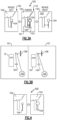
Figure 3A schematically illustrates a quasi-3D simulated parallax effect on a viewscreen achieved by manipulating a distance between objects in an image. -
Figure 3B schematically illustrates a physical scene resulting in the simulated parallax effect ofFigure 3A . -
Figure 4 schematically illustrates another quasi-3D simulated parallax effect achieved by enlarging objects in a foreground. -
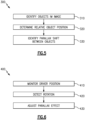
Figure 5 illustrates a method for identifying expected parallax shifting between objects. -
Figure 6 illustrates a method for creating a simulating parallax effect in an at least partially 3D image. - A schematic view of a
commercial vehicle 10 is illustrated inFigures 1A and1B . Thevehicle 10 includes a vehicle cab ortractor 12 for pulling atrailer 14. Although a commercial truck is contemplated in this disclosure, the invention may also be applied to other types of vehicles. Thevehicle 10 incorporates a camera monitoring system (CMS) 15 (Fig. 2 ) that has driver and passengerside camera arms vehicle cab 12. If desired, thecamera arms CMS 15 can be used to entirely replace mirrors. In additional examples, each side can include multiple camera arms, each arm housing one or more cameras and/or mirrors. - Each of the
camera arms cab 12. A pivoting arm is supported by the base and may articulate relative thereto. At least one rearward facingcamera exterior cameras Fig. 1B ), which are legal prescribed views in the commercial trucking industry. Multiple cameras also may be used in eachcamera arm arm CMS 15. - First and second video displays 18a, 18b are arranged on each of the driver and passenger sides within the
vehicle cab 12 on or near the A-pillars 19a, 19b to display Class II and Class IV views on the respective sides of thevehicle 10. The views provide rear facing side views along thevehicle 10 that are captured by theexterior cameras - If video of Class V and Class VI views are also desired, a
camera housing 16c andcamera 20c may be arranged at or near the front of thevehicle 10 to provide those views (Fig. 1B ). Athird display 18c arranged within thecab 12 near the top center of the windshield can be used to display the Class V and Class VI views, which are toward the front of thevehicle 10, to the driver. - If class VIII views are desired, camera housings can be disposed at the sides and rear of the
vehicle 10 to provide fields of view including some or all of the class VIII zones around thevehicle 10. In such examples, thethird display 18c can include one or more frames displaying the class VIII views. Alternatively, additional displays can be added near the first, second andthird displays vehicle 10 cabin allowing the user a good view - The
displays driver region 24 within thecabin 22 where an operator is seated on adriver seat 26. It may be desirable to incorporate a driver monitoring system (DMS) 29 into theCMS 15 to evaluate driver activity in thedriver region 24 and to identify driver parameters that may be indicative of distracted driving or of any other driver characteristic being monitored. Oneexample DMS 29 is illustrated inFigure 2 . First and second interior cameras 28a, 28b are arranged in thevehicle cabin 22 near the first andsecond displays vehicle cabin 22. The first and second interior cameras 28a, 28b respectively provide first and second interior fields of view FOVIN1, FOVIN2 that at least partially overlap one another in thedriver region 24. Thefirst display 18a is positioned such that it is in the second interior field of view FOVIN2, and thesecond display 18b is positioned such that it is in the first interior field of view FOVIN1. Driver activity is determined in at least some examples by monitoring the gaze and/or pose of the driver by using operating the vehicle while using the first and second interior cameras 28a, 28b. - Due to the nature of two-dimensional video imaging, video feed(s) generated by a static camera do not replicate a parallax effect that occurs on physical mirrors. The parallax effect is the effect where the position, size or orientation of an object appears to be different (relative to surrounding objects) when viewed from different positions or angles. By way of example changing an angle that you look at an object can make the object look closer to, or farther away from, another object within your field of view. The shifting relative positions, sizes, and orientations of objects due to the parallax effect aids humans in depth perception and can provide valuable information. In the case of a vehicle operator, the added depth perception of the parallax effect can assist a driver in planning maneuvers to avoid an object and/or prioritizing which object to attempt to avoid when multiple objects are presented. Conventional mirrors, and other reflective surfaces, maintain the parallax effect when used to view objects. Movements that cause the parallax affect to make relative positions of objects to change are referred to as rotations.
- The
CMS 15 included in thevehicle 10 is interconnected with theDMS 29 as described above. A CMS controller within theCMS 15 receives head position, gaze orientation, and/or pose information from theDMS 29 and digitally manipulates the objects in the image corresponding to adjustments in the driver's head position, gaze direction or pose in order to simulate the parallax effect of an actual mirror view. This simulation can be either through adjusting a true 3D image to account for parallax shifts or a partial simulation of parallax shifts using 2D image manipulation, referred to as quasi-3D. The two types of imaging are referred to together as "at least quasi-3D" herein. - With continued reference to
Figures 1a ,1b and2 ,Figure 3A illustrates an exemplary display screen including a view at least two identified objects, atree 102 and asign 104 displayed in aflat 2D image 100. Theimage 100 provides a view of areal scene 101, illustrated inFigure 3B . The actual physical location of theobjects scene 101 does not change when a vehicle operators position causes a rotation. Alternative examples can include any number of additional objects within the image and operate similarly. Theobjects CMS 15 including a neural network analysis of the received image feeds, a rule-based analysis using predetermined image analysis rules, manual identification by the vehicle operator, and the like. The distance between eachobject vehicle 10, and eachobject other object CMS 15, and a "Center"image 110 is generated at thecorresponding display center image 110 is the image as it would appear to an operator looking directly at the display and does not include any parallax manipulation. This image is reflective of theleft scene 101 inFigure 3B . In thecenter image 110, theobjects distance 106. Alternatively, the object identification can occur at a remote controller, a general vehicle controller, or any other processing system configured to identify objects within the image. - When the vehicle operator shifts their gaze, pose, and/or head position to the left, this shift causes a rotation of the of the operator's view relative to the display screen. The
DMS 29 monitors the shift and the relative motion of the driver's viewpoint relative to the display screen, resulting from the rotation, is provided to a parallax control within theCMS 15. The parallax control determines a relative position change between the two or more items corresponding to the parallax shift resulting from the change of perspective. In the example ofFigures 3A and 3B , the driver's rotation causes the twoobjects CMS 15 digitally manipulates the display to move the identifiedobjects Figure 3 , the parallax control determines that the viewpoint rotating left (view 120) will shift thesign 104 closer to the tree within the plane of theimage 100, resulting in an overlap with thesign 104 being in front of the tree. Once this is determined theCMS 15 responds to the identification of a driver's position rotating left, by manipulating theimage 120 to reduce thedistance 106. This process is performed in real time, allowing the operator to continuously rely on the presented images to provide accurate information. - Conversely, when the operator rotates their viewpoint to the right, the
DMS 29 identifies the rotation and informs theCMS 15. TheCMS 15 then identifies that thesign 104 and thetree 102 should appear farther apart, and digitally manipulates theimage 130 to move thesign 104 farther away from thetree 102. - This operation simulates a parallax effect from shifting perspectives and provides additional depth perception, without generating a truly 3D image. In the described example, one of the objects (the tree 102) is used as an anchor point, and all other objects (the sign 104) are moved relative to the anchor point. The anchor point is a position within the image that is maintained "constant". In alternative examples, the anchor point can be identified in the image, and objects can be moved relative to that anchor point. In yet another example, the shift between two
objects objects - In addition to shifting the identified objects, the at least quasi-3D parallax effect is achieved in some examples by altering the relative sizes of the objects based on the head position and gaze direction of the driver. With continued reference to
Figure 1a ,1b ,2 and3, Figure 4 schematically illustrates the parallax effect of altering the relative sizes ofobjects image 200. For ease of explanation, the same scene is illustrated in theimage 200 ofFigure 4 as was used in the scene ofimage 100 inFigure 3 . As with the relative positions example, theDMS 29 rotation of the vehicle operator's viewpoint about the display and alters the relative sizes of theobjects - With reference to both
Figures 3 and 4 , aCMS 15 can further create or enhance the quasi-3D parallax effect by skewingobjects objects CMS 15 can combine the identified quasi-3D parallax effects described herein to further improve the simulated 3D nature. Further, identical process can be applied to a 3D display, allowing for a similar magnitude of parallax simulation and improving the realism and depth of the 3D display. - In one exemplary implementation, the simulated parallax effect is exaggerated within the display in order to assist a driver in more accurately determining the relative positions of objects within the actual scene. The exaggeration can be achieved in one example, by determining that the operator's rotation has exceeded a predefined magnitude (e.g., greater than 15 degrees of rotation) and begin exaggerating the simulated parallax effect by applying a multiplier to the additional rotation beyond 15 degrees. In another example, a smaller magnification is applied constantly to the determined rotation.
- With continued reference to
Figures 1-4 ,Figure 5 illustrates a method for implementing the at least quasi-3D parallax shifting within avehicle 10. Initially theCMS 15 identifies each object within the image in an "Identify Objects within Image"step 310. The objects can be identified as described above, with regards toFigure 3 . Further, in some examples, theCMS 15 can define a "bounding box" (illustrated as boundingboxes 101 and 103) around the identified object and the bounding box defines what is and is not shifted. Alternatively, the object can be re-identified during each operation, depending on the available computational power of theCMS 15. - Once each object within the image is identified, the
CMS 15 determines the relative position of the objects in a "Determine Relative Object Position"step 320. In some examples, a position of each object is determined relative to a single fixed point. The single fixed point can be the identified anchor point within the image, thevehicle 10, or a static object within the image. In some examples, the single fixed point is the anchor point in the image, while in other examples the single fixed point is used only for determining the relative positioning of the objects and the anchor point is dependent on the image. - Once the relative positions of each identified object are determined, the
CMS 15 uses the relative positions of the objects, and the position of the camera(s) capturing the image to determines how the objects will shift, resize, or skew relative to each other in response to the driver rotating their point of view relative to the display in an "Identify Parallax Shift Between Objects"step 330. The parallax shift is determined via comparing sequential images based on a known camera movement, utilizing expected or learned parallax shifts, based on known relative positioning relationships, based on expected positioning, or based on a combination of the two. - Concurrently with the
method 300 ofFigure 5 , theCMS 15 performs amethod 400 that determines how to modify the two or three dimensional image to simulate, or partially simulate, the parallax shift and create an at least partially 3D effect. Initially theCMS 15 uses theDMS 29 to monitor the position and orientation of the drivers head, the pose of the driver and/or the direction of the driver's gaze in a "Monitor Driver Position"step 410. - The
DMS 29 detects a rotation of the vehicle operator about the display in a "Detect Rotation"step 420, and provides a signal to theCMS 15 identifying the change in the monitored characteristic. The identified change includes at least a direction and magnitude of the change. In some examples the head position, operator pose, and the gaze direction are simultaneously monitored, and the detection is a detection of the combined change. - Once the identified detection is provided to the
CMS 15, theCMS 15 responds by shifting the relative position, size, and skew of objects within the image in an "Adjust Parallax Effect"step 430. This process is constantly reiterated during vehicle operation, with the constant adjustments to the parallax effect providing at least quasi-3D by adapting the image to include the shifting parallax effects. - It is appreciated that while example views and figures are included, the examples are simplified and exaggerated for explanatory purposes. In a practical implementation the magnitude of object shifting, resizing, or skewing could be much smaller dependent on which type(s) of quasi-3D parallax effects are being implemented in the given CMS.
- Although an example embodiment has been disclosed, a worker of ordinary skill in this art would recognize that certain modifications would come within the scope of the claims. For that reason, the following claims should be studied to determine their true scope and content.
Claims (15)
- A mirror replacement system for a commercial vehicle comprising:a camera monitoring system, CMS, (15) including at least one camera (20a, 20b), and at least one display (18a, 18b, 18c) configured to display images from the at least one camera (20a, 20b) to a vehicle operator;a driver monitoring system, DMS, (29) including at least one interior camera (28a, 28b), the at least one interior camera (28a, 28b) having a field of view including at least a portion of the vehicle operator's head, the DMS (29) being configured to identify at least one of a head position and orientation of the vehicle operator, a pose of the vehicle operator, and a gaze direction of the vehicle operator; anda controller configured to:detect a shift in at least one of the vehicle operator's head position, the vehicle operator's pose and the vehicle operator's gaze;determine a rotation of the vehicle operator relative to the at least one display (18a, 18b, 18c) based on the detected shift; characterized in that the controller is configured todigitally manipulate at least one image from the CMS (15) by simulating at least one parallax effect corresponding to the determined rotation;wherein the digital manipulation includes an adjustment of a relative position of objects (102, 104) within the at least one image relative to an anchor point; andwherein the anchor point is at least one object (102, 104) in the at least one image, is a focal point of the vehicle operator, or is a position midway between at least two identified objects (102, 104) in the at least one image.
- The mirror replacement system of claim 1, wherein the at least one display (18a, 18b, 18c) includes a first display (18a) disposed at or near a first A-pillar and a second display (18b) disposed at or near a second A-pillar, each of the first display (18a) and the second display (18b) configured to display a corresponding rear view of the vehicle.
- The mirror replacement system of claim 2, wherein the corresponding rear view of the vehicle includes at least one of a Class II and a Class IV view.
- The mirror replacement system of claim 2, wherein the digital manipulation further includes an adjustment of at least one of the relative skew and the relative size of the objects (102, 104) in each display (18a, 18b, 18c) in response to determining the rotation of the vehicle operator relative to the at least one display (18a, 18b, 18c).
- The mirror replacement system of claim 1, wherein the digital manipulation further includes an adjustment of the relative size of the objects (102, 104) in the image and the relative skew of the objects (102, 104) in the image in response to the change in the rotation of the vehicle operator relative to the at least one display (18a, 18b, 18c).
- The mirror replacement system of claim 1, wherein the controller further includes an object identification module configured to distinguish objects (102, 104) within an image feed.
- The mirror replacement system of claim 1, wherein the at least one interior camera (28a, 28b) includes at least two interior cameras (28a, 28b) defining partially overlapping fields of view.
- A method for operating a camera monitoring system comprising:detecting a shift in at least one of a vehicle operator's head position, the vehicle operator's pose and the vehicle operator's gaze;determining a rotation of the vehicle operator relative to a display (18a, 18b, 18c) based on the detected shift; anddigitally manipulating at least one camera monitoring system, CMS, image by simulating at least one parallax effect corresponding to the determined rotation;characterized in thatsaid digitally manipulating the at least one CMS image comprises adjusting a relative position of objects (102, 104) within the at least one CMS image relative to an anchor point;wherein the anchor point is at least one object (102, 104) in the image, is a focal point of the vehicle operator, or is a position midway between at least two identified objects (102, 104) in the image.
- The method of claim 8, wherein digitally manipulating the at least one CMS image further comprises adjusting at least one of a relative size of the objects (102, 104) within the CMS image, and a relative skew of the objects (102, 104) within the CMS image.
- The method of claim 9, wherein digitally manipulating the at least one CMS image comprises adjusting the relative position of the objects (102, 104) within the CMS image, and a relative skew of the objects (102, 104) within the CMS image.
- The method of claim 9, wherein digitally manipulating by adjusting at least one of a relative size of objects (102, 104) within the CMS image, and a relative skew of the objects (102, 104) within the CMS image includes adjusting the image relative to the anchor point.
- The method of claim 8, wherein detecting the rotation of the vehicle operator relative to the display (18a, 18b, 18c) includes monitoring each of the vehicle operator's head position, pose, and gaze position using a driver monitoring system.
- The method of claim 8, wherein the CMS image is a 2D image or a 3D image.
- The method of claim 8, wherein the method is continuously iterated and the at least one CMS image includes a video feed, optionally wherein the video feed includes a first camera (20a) corresponding to a first mirror position and a second camera (20b) corresponding to a second mirror position.
- The method of claim 8, wherein simulating at least one parallax effect comprises magnifying an actual parallax effect and simulating the magnified parallax effect.
Applications Claiming Priority (2)
| Application Number | Priority Date | Filing Date | Title |
|---|---|---|---|
| US202163195207P | 2021-06-01 | 2021-06-01 | |
| PCT/US2022/031329 WO2022256255A1 (en) | 2021-06-01 | 2022-05-27 | Camera monitoring system display including parallax manipulation |
Publications (2)
| Publication Number | Publication Date |
|---|---|
| EP4347314A1 EP4347314A1 (en) | 2024-04-10 |
| EP4347314B1 true EP4347314B1 (en) | 2025-03-12 |
Family
ID=82156447
Family Applications (1)
| Application Number | Title | Priority Date | Filing Date |
|---|---|---|---|
| EP22732822.6A Active EP4347314B1 (en) | 2021-06-01 | 2022-05-27 | Camera monitoring system display including parallax manipulation |
Country Status (3)
| Country | Link |
|---|---|
| US (1) | US12304395B2 (en) |
| EP (1) | EP4347314B1 (en) |
| WO (1) | WO2022256255A1 (en) |
Families Citing this family (1)
| Publication number | Priority date | Publication date | Assignee | Title |
|---|---|---|---|---|
| US12466323B2 (en) | 2024-01-11 | 2025-11-11 | Stoneridge Electronics Ab | Method and apparatus for determining trailer angle |
Family Cites Families (17)
| Publication number | Priority date | Publication date | Assignee | Title |
|---|---|---|---|---|
| US8326483B2 (en) | 2003-02-21 | 2012-12-04 | Gentex Corporation | Monitoring and automatic equipment control systems |
| US9102269B2 (en) | 2011-08-09 | 2015-08-11 | Continental Automotive Systems, Inc. | Field of view matching video display system |
| WO2013086249A2 (en) | 2011-12-09 | 2013-06-13 | Magna Electronics, Inc. | Vehicle vision system with customized display |
| KR101916467B1 (en) | 2012-10-30 | 2018-11-07 | 현대자동차주식회사 | Apparatus and method for detecting obstacle for Around View Monitoring system |
| KR101413231B1 (en) | 2013-02-18 | 2014-06-30 | 인하대학교 산학협력단 | Around view monitoring based on augmented reality device, method and vehicle |
| JP6364702B2 (en) * | 2013-03-29 | 2018-08-01 | アイシン精機株式会社 | Image display control device, image display system, and display unit |
| US9280202B2 (en) | 2013-05-10 | 2016-03-08 | Magna Electronics Inc. | Vehicle vision system |
| US10946798B2 (en) | 2013-06-21 | 2021-03-16 | Magna Electronics Inc. | Vehicle vision system |
| US20150009010A1 (en) | 2013-07-03 | 2015-01-08 | Magna Electronics Inc. | Vehicle vision system with driver detection |
| DE102015202846B4 (en) * | 2014-02-19 | 2020-06-25 | Magna Electronics, Inc. | Vehicle vision system with display |
| US20150294169A1 (en) | 2014-04-10 | 2015-10-15 | Magna Electronics Inc. | Vehicle vision system with driver monitoring |
| US10324297B2 (en) | 2015-11-30 | 2019-06-18 | Magna Electronics Inc. | Heads up display system for vehicle |
| US20180027230A1 (en) * | 2016-07-19 | 2018-01-25 | John T. Kerr | Adjusting Parallax Through the Use of Eye Movements |
| DE102018100194B3 (en) * | 2018-01-05 | 2019-01-03 | Trw Automotive Electronics & Components Gmbh | Mirror replacement system and method for displaying image and / or video data of the environment of a motor vehicle |
| KR102913858B1 (en) * | 2018-12-11 | 2026-01-19 | 소니그룹주식회사 | Image processing device, image processing method, and image processing system |
| WO2020122079A1 (en) * | 2018-12-11 | 2020-06-18 | ソニー株式会社 | Image processing device, image processing method, and image processing system |
| EP3896960B1 (en) * | 2018-12-11 | 2025-11-26 | Sony Group Corporation | Image processing device, image processing method, and image processing system |
-
2022
- 2022-05-27 WO PCT/US2022/031329 patent/WO2022256255A1/en not_active Ceased
- 2022-05-27 US US18/566,187 patent/US12304395B2/en active Active
- 2022-05-27 EP EP22732822.6A patent/EP4347314B1/en active Active
Also Published As
| Publication number | Publication date |
|---|---|
| WO2022256255A1 (en) | 2022-12-08 |
| EP4347314A1 (en) | 2024-04-10 |
| US20240253568A1 (en) | 2024-08-01 |
| US12304395B2 (en) | 2025-05-20 |
Similar Documents
| Publication | Publication Date | Title |
|---|---|---|
| EP1701306B1 (en) | Driving support system | |
| US10647256B2 (en) | Method for providing a rear mirror view of a surroundings of a vehicle | |
| US9102269B2 (en) | Field of view matching video display system | |
| JP5320970B2 (en) | Vehicle display device and display method | |
| JP7831772B2 (en) | Tracking of the trailer end in a camera surveillance system | |
| US20160297362A1 (en) | Vehicle exterior side-camera systems and methods | |
| US20130096820A1 (en) | Virtual display system for a vehicle | |
| KR20010112433A (en) | Image processing device and monitoring system | |
| EP3772719B1 (en) | Image processing apparatus, image processing method, and image processing program | |
| DE102014115037A1 (en) | Vision-based object recognition and highlighting in vehicle image display systems | |
| CN107438538A (en) | Method for displaying vehicle surroundings of a vehicle | |
| CN111277796A (en) | Image processing method, vehicle-mounted vision auxiliary system and storage device | |
| KR20180020274A (en) | Panel conversion | |
| EP3326146B1 (en) | Rear cross traffic - quick looks | |
| CN115018942A (en) | Method and apparatus for image display of vehicle | |
| EP4347314B1 (en) | Camera monitoring system display including parallax manipulation | |
| JP2005269010A (en) | Image creating device, program and method | |
| US12498235B2 (en) | Vehicle camera system for view creation of viewing locations | |
| CN109764888A (en) | Display system and display methods | |
| JP2008042235A (en) | Vehicle display device | |
| CN110831803A (en) | Method, device and computer program for operating a vehicle operating system | |
| US10933812B1 (en) | Outside-vehicle environment monitoring apparatus | |
| US20240291954A1 (en) | Camera system and method for a camera system | |
| GB2563647A (en) | Method of displaying an image | |
| JP2016136326A (en) | Information display apparatus and information display method |
Legal Events
| Date | Code | Title | Description |
|---|---|---|---|
| STAA | Information on the status of an ep patent application or granted ep patent |
Free format text: STATUS: UNKNOWN |
|
| STAA | Information on the status of an ep patent application or granted ep patent |
Free format text: STATUS: THE INTERNATIONAL PUBLICATION HAS BEEN MADE |
|
| PUAI | Public reference made under article 153(3) epc to a published international application that has entered the european phase |
Free format text: ORIGINAL CODE: 0009012 |
|
| STAA | Information on the status of an ep patent application or granted ep patent |
Free format text: STATUS: REQUEST FOR EXAMINATION WAS MADE |
|
| 17P | Request for examination filed |
Effective date: 20231102 |
|
| AK | Designated contracting states |
Kind code of ref document: A1 Designated state(s): AL AT BE BG CH CY CZ DE DK EE ES FI FR GB GR HR HU IE IS IT LI LT LU LV MC MK MT NL NO PL PT RO RS SE SI SK SM TR |
|
| DAV | Request for validation of the european patent (deleted) | ||
| DAX | Request for extension of the european patent (deleted) | ||
| GRAP | Despatch of communication of intention to grant a patent |
Free format text: ORIGINAL CODE: EPIDOSNIGR1 |
|
| STAA | Information on the status of an ep patent application or granted ep patent |
Free format text: STATUS: GRANT OF PATENT IS INTENDED |
|
| INTG | Intention to grant announced |
Effective date: 20241004 |
|
| GRAS | Grant fee paid |
Free format text: ORIGINAL CODE: EPIDOSNIGR3 |
|
| GRAA | (expected) grant |
Free format text: ORIGINAL CODE: 0009210 |
|
| STAA | Information on the status of an ep patent application or granted ep patent |
Free format text: STATUS: THE PATENT HAS BEEN GRANTED |
|
| AK | Designated contracting states |
Kind code of ref document: B1 Designated state(s): AL AT BE BG CH CY CZ DE DK EE ES FI FR GB GR HR HU IE IS IT LI LT LU LV MC MK MT NL NO PL PT RO RS SE SI SK SM TR |
|
| REG | Reference to a national code |
Ref country code: GB Ref legal event code: FG4D |
|
| REG | Reference to a national code |
Ref country code: CH Ref legal event code: EP |
|
| REG | Reference to a national code |
Ref country code: DE Ref legal event code: R096 Ref document number: 602022011761 Country of ref document: DE |
|
| REG | Reference to a national code |
Ref country code: IE Ref legal event code: FG4D |
|
| REG | Reference to a national code |
Ref country code: SE Ref legal event code: TRGR |
|
| PG25 | Lapsed in a contracting state [announced via postgrant information from national office to epo] |
Ref country code: RS Free format text: LAPSE BECAUSE OF FAILURE TO SUBMIT A TRANSLATION OF THE DESCRIPTION OR TO PAY THE FEE WITHIN THE PRESCRIBED TIME-LIMIT Effective date: 20250612 |
|
| PG25 | Lapsed in a contracting state [announced via postgrant information from national office to epo] |
Ref country code: FI Free format text: LAPSE BECAUSE OF FAILURE TO SUBMIT A TRANSLATION OF THE DESCRIPTION OR TO PAY THE FEE WITHIN THE PRESCRIBED TIME-LIMIT Effective date: 20250312 |
|
| PG25 | Lapsed in a contracting state [announced via postgrant information from national office to epo] |
Ref country code: ES Free format text: LAPSE BECAUSE OF FAILURE TO SUBMIT A TRANSLATION OF THE DESCRIPTION OR TO PAY THE FEE WITHIN THE PRESCRIBED TIME-LIMIT Effective date: 20250312 |
|
| REG | Reference to a national code |
Ref country code: LT Ref legal event code: MG9D |
|
| PG25 | Lapsed in a contracting state [announced via postgrant information from national office to epo] |
Ref country code: NO Free format text: LAPSE BECAUSE OF FAILURE TO SUBMIT A TRANSLATION OF THE DESCRIPTION OR TO PAY THE FEE WITHIN THE PRESCRIBED TIME-LIMIT Effective date: 20250612 |
|
| PG25 | Lapsed in a contracting state [announced via postgrant information from national office to epo] |
Ref country code: HR Free format text: LAPSE BECAUSE OF FAILURE TO SUBMIT A TRANSLATION OF THE DESCRIPTION OR TO PAY THE FEE WITHIN THE PRESCRIBED TIME-LIMIT Effective date: 20250312 |
|
| REG | Reference to a national code |
Ref country code: NL Ref legal event code: MP Effective date: 20250312 |
|
| PG25 | Lapsed in a contracting state [announced via postgrant information from national office to epo] |
Ref country code: LV Free format text: LAPSE BECAUSE OF FAILURE TO SUBMIT A TRANSLATION OF THE DESCRIPTION OR TO PAY THE FEE WITHIN THE PRESCRIBED TIME-LIMIT Effective date: 20250312 |
|
| PG25 | Lapsed in a contracting state [announced via postgrant information from national office to epo] |
Ref country code: BG Free format text: LAPSE BECAUSE OF FAILURE TO SUBMIT A TRANSLATION OF THE DESCRIPTION OR TO PAY THE FEE WITHIN THE PRESCRIBED TIME-LIMIT Effective date: 20250312 Ref country code: GR Free format text: LAPSE BECAUSE OF FAILURE TO SUBMIT A TRANSLATION OF THE DESCRIPTION OR TO PAY THE FEE WITHIN THE PRESCRIBED TIME-LIMIT Effective date: 20250613 |
|
| REG | Reference to a national code |
Ref country code: AT Ref legal event code: MK05 Ref document number: 1774774 Country of ref document: AT Kind code of ref document: T Effective date: 20250312 |
|
| PG25 | Lapsed in a contracting state [announced via postgrant information from national office to epo] |
Ref country code: NL Free format text: LAPSE BECAUSE OF FAILURE TO SUBMIT A TRANSLATION OF THE DESCRIPTION OR TO PAY THE FEE WITHIN THE PRESCRIBED TIME-LIMIT Effective date: 20250312 |
|
| PG25 | Lapsed in a contracting state [announced via postgrant information from national office to epo] |
Ref country code: SM Free format text: LAPSE BECAUSE OF FAILURE TO SUBMIT A TRANSLATION OF THE DESCRIPTION OR TO PAY THE FEE WITHIN THE PRESCRIBED TIME-LIMIT Effective date: 20250312 |
|
| PG25 | Lapsed in a contracting state [announced via postgrant information from national office to epo] |
Ref country code: PT Free format text: LAPSE BECAUSE OF FAILURE TO SUBMIT A TRANSLATION OF THE DESCRIPTION OR TO PAY THE FEE WITHIN THE PRESCRIBED TIME-LIMIT Effective date: 20250714 |
|
| PGFP | Annual fee paid to national office [announced via postgrant information from national office to epo] |
Ref country code: DE Payment date: 20250819 Year of fee payment: 4 |
|
| PG25 | Lapsed in a contracting state [announced via postgrant information from national office to epo] |
Ref country code: IT Free format text: LAPSE BECAUSE OF FAILURE TO SUBMIT A TRANSLATION OF THE DESCRIPTION OR TO PAY THE FEE WITHIN THE PRESCRIBED TIME-LIMIT Effective date: 20250312 Ref country code: PL Free format text: LAPSE BECAUSE OF FAILURE TO SUBMIT A TRANSLATION OF THE DESCRIPTION OR TO PAY THE FEE WITHIN THE PRESCRIBED TIME-LIMIT Effective date: 20250312 |
|
| PG25 | Lapsed in a contracting state [announced via postgrant information from national office to epo] |
Ref country code: AT Free format text: LAPSE BECAUSE OF FAILURE TO SUBMIT A TRANSLATION OF THE DESCRIPTION OR TO PAY THE FEE WITHIN THE PRESCRIBED TIME-LIMIT Effective date: 20250312 |
|
| PGFP | Annual fee paid to national office [announced via postgrant information from national office to epo] |
Ref country code: SE Payment date: 20250821 Year of fee payment: 4 |
|
| PG25 | Lapsed in a contracting state [announced via postgrant information from national office to epo] |
Ref country code: EE Free format text: LAPSE BECAUSE OF FAILURE TO SUBMIT A TRANSLATION OF THE DESCRIPTION OR TO PAY THE FEE WITHIN THE PRESCRIBED TIME-LIMIT Effective date: 20250312 Ref country code: CZ Free format text: LAPSE BECAUSE OF FAILURE TO SUBMIT A TRANSLATION OF THE DESCRIPTION OR TO PAY THE FEE WITHIN THE PRESCRIBED TIME-LIMIT Effective date: 20250312 |
|
| PG25 | Lapsed in a contracting state [announced via postgrant information from national office to epo] |
Ref country code: RO Free format text: LAPSE BECAUSE OF FAILURE TO SUBMIT A TRANSLATION OF THE DESCRIPTION OR TO PAY THE FEE WITHIN THE PRESCRIBED TIME-LIMIT Effective date: 20250312 |
|
| PG25 | Lapsed in a contracting state [announced via postgrant information from national office to epo] |
Ref country code: SK Free format text: LAPSE BECAUSE OF FAILURE TO SUBMIT A TRANSLATION OF THE DESCRIPTION OR TO PAY THE FEE WITHIN THE PRESCRIBED TIME-LIMIT Effective date: 20250312 |
|
| PG25 | Lapsed in a contracting state [announced via postgrant information from national office to epo] |
Ref country code: IS Free format text: LAPSE BECAUSE OF FAILURE TO SUBMIT A TRANSLATION OF THE DESCRIPTION OR TO PAY THE FEE WITHIN THE PRESCRIBED TIME-LIMIT Effective date: 20250712 |
|
| REG | Reference to a national code |
Ref country code: DE Ref legal event code: R097 Ref document number: 602022011761 Country of ref document: DE |
|
| REG | Reference to a national code |
Ref country code: CH Ref legal event code: H13 Free format text: ST27 STATUS EVENT CODE: U-0-0-H10-H13 (AS PROVIDED BY THE NATIONAL OFFICE) Effective date: 20251223 |
|
| PG25 | Lapsed in a contracting state [announced via postgrant information from national office to epo] |
Ref country code: DK Free format text: LAPSE BECAUSE OF FAILURE TO SUBMIT A TRANSLATION OF THE DESCRIPTION OR TO PAY THE FEE WITHIN THE PRESCRIBED TIME-LIMIT Effective date: 20250312 |
|
| PG25 | Lapsed in a contracting state [announced via postgrant information from national office to epo] |
Ref country code: LU Free format text: LAPSE BECAUSE OF NON-PAYMENT OF DUE FEES Effective date: 20250527 |
|
| PLBE | No opposition filed within time limit |
Free format text: ORIGINAL CODE: 0009261 |
|
| STAA | Information on the status of an ep patent application or granted ep patent |
Free format text: STATUS: NO OPPOSITION FILED WITHIN TIME LIMIT |
|
| PG25 | Lapsed in a contracting state [announced via postgrant information from national office to epo] |
Ref country code: CH Free format text: LAPSE BECAUSE OF NON-PAYMENT OF DUE FEES Effective date: 20250531 |
|
| REG | Reference to a national code |
Ref country code: CH Ref legal event code: L10 Free format text: ST27 STATUS EVENT CODE: U-0-0-L10-L00 (AS PROVIDED BY THE NATIONAL OFFICE) Effective date: 20260121 |
|
| REG | Reference to a national code |
Ref country code: BE Ref legal event code: MM Effective date: 20250531 |
|
| PG25 | Lapsed in a contracting state [announced via postgrant information from national office to epo] |
Ref country code: MC Free format text: LAPSE BECAUSE OF FAILURE TO SUBMIT A TRANSLATION OF THE DESCRIPTION OR TO PAY THE FEE WITHIN THE PRESCRIBED TIME-LIMIT Effective date: 20250312 |
|
| 26N | No opposition filed |
Effective date: 20251215 |
|
| PG25 | Lapsed in a contracting state [announced via postgrant information from national office to epo] |
Ref country code: IE Free format text: LAPSE BECAUSE OF NON-PAYMENT OF DUE FEES Effective date: 20250527 |
|
| PG25 | Lapsed in a contracting state [announced via postgrant information from national office to epo] |
Ref country code: BE Free format text: LAPSE BECAUSE OF NON-PAYMENT OF DUE FEES Effective date: 20250531 |
|
| PG25 | Lapsed in a contracting state [announced via postgrant information from national office to epo] |
Ref country code: FR Free format text: LAPSE BECAUSE OF NON-PAYMENT OF DUE FEES Effective date: 20250531 |