EP4346188A1 - Control device, control method, and control program using distribution source and destination lists - Google Patents
Control device, control method, and control program using distribution source and destination lists Download PDFInfo
- Publication number
- EP4346188A1 EP4346188A1 EP23181725.5A EP23181725A EP4346188A1 EP 4346188 A1 EP4346188 A1 EP 4346188A1 EP 23181725 A EP23181725 A EP 23181725A EP 4346188 A1 EP4346188 A1 EP 4346188A1
- Authority
- EP
- European Patent Office
- Prior art keywords
- control device
- node
- list
- control
- distribution source
- Prior art date
- Legal status (The legal status is an assumption and is not a legal conclusion. Google has not performed a legal analysis and makes no representation as to the accuracy of the status listed.)
- Granted
Links
Images






















Classifications
-
- G—PHYSICS
- G05—CONTROLLING; REGULATING
- G05B—CONTROL OR REGULATING SYSTEMS IN GENERAL; FUNCTIONAL ELEMENTS OF SUCH SYSTEMS; MONITORING OR TESTING ARRANGEMENTS FOR SUCH SYSTEMS OR ELEMENTS
- G05B15/00—Systems controlled by a computer
- G05B15/02—Systems controlled by a computer electric
-
- H—ELECTRICITY
- H04—ELECTRIC COMMUNICATION TECHNIQUE
- H04L—TRANSMISSION OF DIGITAL INFORMATION, e.g. TELEGRAPHIC COMMUNICATION
- H04L67/00—Network arrangements or protocols for supporting network services or applications
- H04L67/01—Protocols
- H04L67/10—Protocols in which an application is distributed across nodes in the network
- H04L67/104—Peer-to-peer [P2P] networks
- H04L67/1042—Peer-to-peer [P2P] networks using topology management mechanisms
Definitions
- the embodiment discussed herein is related to a control system and the like.
- each organization not only requests an organization as a data generation source to provide data but also performs nth-order transmission of the data.
- FIG. 46 is a diagram for explaining the nth-order transmission.
- Primary to tertiary transmission will be described in the description of FIG. 46 .
- terminal devices used by first to fourth organizations will be described as nodes A, B, C, and D, respectively.
- the node A transmits data X to the node B.
- the node B transmits the data X received from the node A to the node C.
- the node C transmits the data X received from the node B to the node D.
- FIGs. 47 and 48 are diagrams for explaining the function needed in the nth-order transmission. Functions (1) and (2) needed in the nth-order transmission will be described with reference to FIG. 47 . A function (3) needed in the nth-order transmission will be described with reference to FIG. 48 .
- terminal devices used by first to sixth organizations will be described as nodes A, B, C, C', D, and E, respectively. It is assumed that data transmission destinations of the nodes A to E are set in advance. For example, the node A transmits data to the node B. The node B transmits the data to the node C or to the node C'. The node C transmits the data to the node D. The node C' transmits the data to the node D. The node D transmits the data to the node E.
- the function (1) needed in the nth-order transmission is a function in which a transmission destination node (node that has received data) is enabled to grasp a route through which the data has been distributed (list of nodes involved in transmission: distribution source list).
- the route is indicated using a right arrow " ⁇ ".
- n1 ⁇ n2 ⁇ n3 indicates that the data route is a route that sequentially passes a node n1, a node n2, and a node n3.
- a distribution source list 10as is set in the node A
- a distribution source list 10c's is set in the node C'
- a distribution source list 10es is set in the node E.
- Description of distribution source lists of other nodes will be omitted. Since the node A is the most upstream node, the distribution source list 10as is an empty set. "A ⁇ B" is set in the distribution source list 10c's. "A ⁇ B ⁇ C ⁇ D" and "A ⁇ B ⁇ C' ⁇ D" are set in the distribution source list 10es.
- the function (2) needed in the nth-order transmission is a function in which, in a case where data transmitted from a transmission source node to an adjacent node is transmitted to another node, a route thereof (list of nodes involved in transmission: distribution destination list) may be grasped.
- a distribution destination list 10ad is set in the node A
- a distribution destination list 10c'd is set in the node C'
- a distribution destination list 10ed is set in the node E.
- Description of distribution destination lists of other nodes will be omitted.
- "B ⁇ C ⁇ D ⁇ E” and "B ⁇ C' ⁇ D -> E” are set in the distribution destination list 10ad.
- "D ⁇ E" is set in the distribution destination list 10c'd. Since the node E is the most downstream node, the distribution destination list 10ed is an empty set.
- the function (3) needed in the nth-order transmission is a function in which a node is enabled to cancel data transmission.
- the function (3) in a case where a node cancels transmission and the transmission destination node has transmitted the corresponding data to another node, subsequent transmission is also canceled in a chained manner.
- the node B cancels transmission of the data X to the node C
- the distribution destination list and the distribution source list are updated according to the transmission cancellation.
- each node transmits and receives data in an autonomously distributed manner
- the functions (1) to (3) described above are not provided, and each node may not correctly grasp the data distribution source and the data distribution destination. Furthermore, when data transmission cancellation occurs, each node may not update the distribution source list and the distribution destination list.
- FIG. 49 is a diagram for explaining a problem of an existing technique.
- a distribution destination and a distribution source that may be independently grasped by each node are only nodes that have directly transmitted and received data.
- a viewpoint of the node A is a viewpoint 11a.
- the node A grasps only the transmission destination node B.
- a viewpoint of the node B is a viewpoint 11b.
- the node B grasps the transmission source node A, and the transmission destination nodes C and C'.
- a viewpoint of the node C is a viewpoint 11c.
- the node C grasps the transmission source node B, and the transmission destination node D.
- a viewpoint of the node C' is a viewpoint 11c'.
- the node C' grasps the transmission source node B, and the transmission destination node D.
- a viewpoint of the node D is a viewpoint 11d.
- the node D grasps the transmission source nodes C and C', and the transmission destination node E.
- a viewpoint of the node E is a viewpoint 11e.
- the node E grasps the transmission source node D.
- the node A desires to grasp information regarding the distribution destination list 10ad described in FIG. 47 , it may grasp only up to the transmission destination node B.
- the node C desires to grasp the distribution source "A ⁇ B" before the node B and the distribution destination "D ⁇ E" after D, it may grasp only up to the node B as the distribution source and the node D as the distribution destination. Note that the node C is not to grasp the distribution route "B ⁇ C' ⁇ D ⁇ E" that the node C is not involved in.
- each node needs to correctly grasp the data distribution source and the data distribution destination.
- an object of the embodiment is to provide a control system, a control device, a control method, and a control program that enable each node to correctly grasp a data distribution source and a data distribution destination in nth-order transmission.
- a control system including a plurality of control devices configured to perform nth-order transmission, wherein each control device of the plurality of control devices includes: a storage device configured to store, in relation to the plurality of control devices, a distribution source list that stores a list of the plurality of control devices to be passed through from a most upstream control device to the control device and a distribution destination list that stores a list of the plurality of control devices to be passed through from the control device to a most downstream control device; and a processor coupled to the storage device, the processor being configured to perform control processing including: in a case where an update request in which a first distribution source list of a first control device being any one of the plurality of control devices is set is received, updating the distribution source list based on the update request, generating a new update request based on the updated distribution source list, and transmitting the new update request to a second control device being any one of the plurality of control devices other than the first control device; and in a case where an update request in which a first distribution source list of
- Each node is enabled to correctly grasp a data distribution source and a data distribution destination in the nth-order transmission.
- FIG. 1 is a diagram illustrating the control system according to the present embodiment.
- the control system includes nodes 100A, 100B, 100C, 100C', 100D, and 100E.
- the nodes 100A to 100E transmits and receives data in an autonomously distributed manner to carry out nth-order transmission.
- the most upstream node is assumed to be the node 100A, and the most downstream node is assumed to be the node 100E.
- the nodes 100A to 100E are examples of a "control device".
- the distribution source list src i is a set of lists of nodes that have been passed through from the most upstream node 100A to the node 100i.
- the distribution destination list dst i is a set of lists of nodes to be passed through from the node 100i to the most downstream node 100E.
- An initial value of the distribution source list src i and the distribution destination list dst i is an empty set ⁇ .
- an adjacent node to which the node 100i transmits data is determined in advance by an organization that manages the node 100i.
- the node 100A is coupled to the node 100B, and transmits data to the node 100B.
- the node 100A has management information 50A.
- the management information 50A stores a distribution source list src A (may be referred to as “srcA”, “src_A”, or the like) and a distribution destination list dst A (may be referred to as "dstA”, "dst_A”, or the like).
- the node 100B is coupled to the nodes 100A, 100C, and 100C', and transmits the data to the node 100C or to the node 100C'.
- the node 100B has management information 50B.
- the management information 50B stores a distribution source list src B (may be referred to as “srcB”, “src_B”, or the like) and a distribution destination list dst B (may be referred to as "dstB", "dst_B”, or the like)
- the node 100C is coupled to the nodes 100B and 100D, and transmits the data to the node 100D.
- the node 100C has management information 50C.
- the management information 50C stores a distribution source list srcc (may be referred to as “srcC”, “src_C”, or the like) and a distribution destination list dst C (may be referred to as “dstC”, "dst_C”, or the like).
- the node 100C' is coupled to the nodes 100B and 100D, and transmits the data to the node 100D.
- the node 100C' has management information 50C'.
- the management information 50C' stores a distribution source list srcC' (may be referred to as “srcC'”, “src_C'”, or the like) and a distribution destination list dst C , (may be referred to as "dstC'", “dst_C'”, or the like)
- the node 100D is coupled to the nodes 100C, 100C', and 100E, and transmits the data to the node 100E.
- the node 100D has management information 50D.
- the management information 50D stores a distribution source list src D (may be referred to as “srcD”, “src_D”, or the like) and a distribution destination list dst D (may be referred to as "dstD”, "dst_D”, or the like).
- the node 100E is coupled to the node 100D.
- the node 100E has management information 50E.
- the management information 50E stores a distribution source list src E (may be referred to as “srcE”, “src_E”, or the like) and a distribution destination list dst E (may be referred to as “dstE”, “dst_E”, or the like).
- a node updates its own management information at the time of data transmission and reception, and transmits an update request of another piece of management information to another node.
- the node that has received the update request of the management information updates the management information, and transmits an update request of management information to still another node when a specific condition is satisfied.
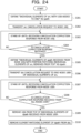
- FIG. 2 is a flowchart (1) illustrating the processing procedure (Forward) at the time of transmission.
- FIG. 2 a case where the node 100i transmits data to a node 100j will be described.
- the node 100i transmits an update request (src i ) to the node 100j (step S101).
- the node 100i stands by until receiving an update completion response (dst j ) from the node 100j (step S102).
- the "update request (src i )” means to be an update request including the distribution source list src i of the node 100i
- the "update completion response (dst j )” means to be a completion response including the distribution destination list dst j of the node 100j.
- step S103 If the node 100i fails to receive the update completion response (No in step S103), the process proceeds to step S102. If the node 100i has received the update completion response (Yes in step S103), the process proceeds to step S104.
- the node 100i adds, to the distribution destination list dst i , "individual elements of dst j with the node 100j added to the top thereof" (step S104). Thereby, identification information of the node 100j and each element included in the dst j are added to the distribution destination list dst i of the node 100i.
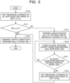
- FIG. 3 is a flowchart (2) illustrating the processing procedure (Forward) at the time of transmission.
- FIG. 3 illustrates a processing procedure of a node 100y in a case where an update request is transmitted from a node 100x to the node 100y.
- the node 100x is any one node of the nodes 100A to 100E.
- the node y is any one node of the nodes 100A to 100E that has received the update request from the node x.
- the node 100y adds, to the distribution source list src y , "individual elements of src x with the node 100x added to the end thereof"(step S110). Thereby, identification information of the node 100x and each element included in the src x are added to the distribution source list src y of the node 100y.
- the node 100y transmits the update request (src y ) to a node 100z (which may be a plurality of nodes) at the top of individual elements of dst y (step S113).
- the node 100y stands by until receiving an update completion response (dst z ) from the node 100z (step S114). If the node 100y has not received the update completion response from all the nodes 100z (No in step S115), the process proceeds to step S114.
- step S115 If the node 100y has received the update completion response from all the nodes 100z (Yes in step S115), the process proceeds to step S116.
- the node 100y adds "individual elements of dst z with the node 100z added to the top thereof" to dst y (step S116), and the process proceeds to step S112.
- the node 100y recursively executes the process when the update request is received, which has been described with reference to FIG. 3 , until dst y becomes an empty set.
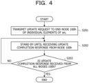
- FIG. 4 is a flowchart (1) illustrating the processing procedure (Backward) at the time of transmission.
- FIG. 4 a case where the node 100i transmits data to the node 100j will be described.
- the node 100i transmits an update request to a node 100h (which may be a plurality of nodes) at the end of individual elements of src i (step S201).
- the node 100i stands by until receiving an update completion response from the node 100h (step S202).
- step S203 If the node 100i has not received the update completion response from all the nodes 100h (No in step S203), the process proceeds to step S202.
- step S203 If the node 100i has received the update completion response from all the nodes 100h (Yes in step S203), the process is terminated.
- FIG. 5 is a flowchart (2) illustrating the processing procedure (Backward) at the time of transmission.
- FIG. 5 illustrates a processing procedure of the node 100y in a case where an update request is transmitted from the node 100z to the node 100y.
- the node 100y adds "individual elements of dst z with the node 100z added to the end thereof" to dst y (step S210).
- the node 100y transmits the update request to the node 100x (which may be a plurality of nodes) at the end of individual elements of src y (step S213).
- the node 100y stands by until receiving an update completion response from the node 100x (step S214).
- step S212 If the node 100y has not received the update completion response from all the nodes 100x (No in step S215), the process proceeds to step S214. If the node 100y has received the update completion response from all the nodes 100x (Yes in step S215), the process proceeds to step S212.
- the node 100y recursively executes the process when the update request is received, which has been described with reference to FIG. 5 , until dst y becomes an empty set.
- FIGs. 6 to 23 are diagrams for explaining a process at the time of node transmission.
- FIG. 6 will be described.
- the node 100D transmits an update request "srcD" to the node at the top of individual elements of dstD.
- the node 100D transmits the update request "srcD" to the node 100E.
- the node 100E merges "100A, 100B, 100C', 100D” obtained by adding "100D” to the end of individual elements of srcD with srcE.
- the node 100D transmits an update completion response "dstd" to the node 100C'.
- the node 100B transmits an update request "dstB" to the node at the end of the individual elements of the distribution source list srcB.
- the node 100B transmits the update request "dstB" to the node 100A.
- the node 100A merges "100B, 100C', 100D, 100E” obtained by adding 100B to the top of the individual elements of dstB with dstA.
- the node 100B receives the update completion response.
- the node 100B stands by until receiving the update completion response for all the transmitted update requests.
- the node 100B transmits an update completion response to the node 100C'.
- the node 100C' receives the update completion response.
- the node 100C' stands by until receiving the update completion response for all the transmitted update requests.
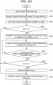
- FIGs. 24 to 26 are flowcharts illustrating the processing procedure at the time of transmission cancellation by the node.
- FIG. 24 will be described.
- the node 100i transmits data (spath) related to transmission cancellation to the node 100j
- the node 100i defines as spath, "individual elements of srci with the 100i added to the end thereof"(step S301).
- the node 100i transmits a "src cancellation request" (spath) to the node 100j (step S302).
- src cancellation request means to be a cancellation request including the data "spath”.
- the node 100i stands by until receiving a cancellation completion response from the node 100j (step S303). If the node 100i fails the receive the cancellation completion response (No in step S304), the process proceeds to step S303.
- step S305 The node 100i defines as dpath, "individual elements of spath received from the node 100j with a portion matching the individual elements of srci removed from the top thereof" (step S305).
- the node 100i transmits a dst cancellation request (dpath) to the node 100h at the end of the individual elements of srci (step S306). It is noted that the "dst cancellation request (dpath)" means to be a cancellation request including the data "dpath”.
- the node 100i stands by until receiving a cancellation completion response from the node 100h (step S307). If the node 100i has not received the cancellation completion response from all the nodes 100h (No in step S308), the process proceeds to step S307.
- step S308 if the node 100i has received the cancellation completion response (dpath) from all the nodes 100h (Yes in step S308), the process proceeds to step S309.
- the node 100i removes 100i from the top of the individual elements of dpath received from the node 100h (step S309).
- the node 100i removes, from dsti, an element matching the element of dpath (step S310).
- FIG. 25 illustrates a processing procedure of the node 100y in a case where a cancellation request is transmitted from the node 100x to the node 100y.
- the node 100y receives spath (cancellation request) from the node 100x (step S401).
- the node 100y removes, from srcy, an element matching the element of spath (step S402).
- the node 100y adds 100y to the end of the individual elements of spath (step S403).
- the node 100y transmits a src cancellation request (spath) to the node 100z at the top of the individual elements of dsty (step S405).
- the node 100y stands by until receiving a cancellation completion response from the node 100z (step S406). If the node 100y has not received the cancellation completion response from all the nodes 100z (No in step S407), the process proceeds to step S406.
- step S408 the node 100y deletes the element of dsty (step S409).
- the node 100y transmits a cancellation completion response (spath) to the node 100x (step S410).
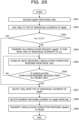
- FIG. 26 illustrates a processing procedure of the node 100y in a case where a dst cancellation request (dpath) is transmitted from the node 100z to the node 100y.
- dpath dst cancellation request
- the node 100y receives dpath from the node 100z (step S501).
- the node 100y adds 100y to the top of the individual elements of dpath (step S502).
- step S503 the node 100y transmits the dst cancellation request (dpath) to the node 100x at the end of the individual elements of srcy (step S504).
- the node 100y stands by until receiving a cancellation completion response from the node 100x (step S505). If the node 100y has not received the cancellation completion response from all the nodes 100x (No in step S506), the process proceeds to step S505.
- step S506 if the node 100y has received the cancellation completion response from all the nodes 100x (Yes in step S506), the process proceeds to step S507.
- the node 100y deletes 100y from the top of the individual elements of dpath (step S507).
- the node 100y deletes, from dsty, an element matching the element of dpath (step S508).
- the node 100y transmits a cancellation completion response (dpath) to the node 100z (step S509).
- FIGs. 27 to 42 are diagrams for explaining the process at the time of transmission cancellation.
- FIG. 27 will be described.
- the node 100B performs the following process in a case of canceling data transmission from the node 100B to the node 100C.
- the node 100A performs the following process.
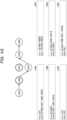
- the management information 50A and 50B retain the information illustrated in FIG. 42 .
- the node 100i is enabled to appropriately update the distribution source list and the distribution destination list when data transmission cancellation occurs.
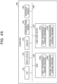
- FIG. 43 is a functional block diagram illustrating a node configuration according to the present embodiment. As illustrated in FIG. 43 , the node 100i includes a communication unit 110, an input unit 120, a display unit 130, a storage unit 140, and a control unit 150.
- the communication unit 110 executes data communication with an external device and the like via a network.
- the control unit 150 to be described later exchanges data with an external device via the communication unit 110.
- the input unit 120 is an input device that inputs various types of information to the control unit 150 of the node 100i.
- the input unit 120 corresponds to a keyboard, a mouse, a touch panel, or the like.
- the display unit 130 is a display device that displays information output from the control unit 150.
- the storage unit 140 has the management information 50i.
- the storage unit 140 corresponds to a semiconductor memory element such as a random access memory (RAM) or a flash memory, or a storage device such as a hard disk drive (HDD).
- RAM random access memory
- HDD hard disk drive
- the management information 50i stores the distribution source list srci and the distribution destination list dsti.
- FIG. 44 is a diagram illustrating an exemplary data structure of the management information. As illustrated in FIG. 44 , the management information 50i associates data ID, the distribution source list srci, and the distribution destination list dsti.
- the data ID is an identification number assigned to each data to be subject to the nth-order transmission, and is used to identify the distribution source list srci and the distribution destination list dsti of each node. For example, each of the individual distribution source lists srci and distribution destination lists dsti illustrated in FIGs. 6 to 23 and FIGs. 27 to 42 is associated with the same data ID.
- the distribution source list srci is a set of lists of nodes that have been passed through from the most upstream node (e.g., node 100A) to the node 100i.
- the distribution destination list dsti is a set of lists of nodes to be passed through from the node 100i to the most downstream node (e.g., node 100E).
- the control unit 150 includes a first transmission control unit 151 and a second transmission control unit 152.
- the control unit 150 is implemented by a central processing unit (CPU), a graphics processing unit (GPU), a hard-wired logic such as an application specific integrated circuit (ASIC) or a field programmable gate array (FPGA), or the like.
- CPU central processing unit
- GPU graphics processing unit
- ASIC application specific integrated circuit
- FPGA field programmable gate array
- the first transmission control unit 151 executes the data transmission (Forward) from the upstream side to the downstream side described with reference to FIGs. 2 and 3 . Furthermore, the first transmission control unit 151 executes the data transmission (Backward) from the downstream side to the upstream side described with reference to FIGs. 4 and 5 . With the first transmission control unit 151 of each of the nodes 100A to 100E executing the processes of FIGs. 2 to 5 , data of the management information 50A to 50E becomes the data illustrated in FIG. 23 , whereby the nodes 100A to 100E are enabled to correctly grasp the data distribution source and the data distribution destination.
- the first transmission control unit 151 receives an update request in which a distribution source list of the upstream adjacent node is set, it updates the distribution source list based on the update request, generates a new update request based on the updated distribution source list, and transmits the new update request to the downstream adjacent node.
- the first transmission control unit 151 receives an update completion response in which a distribution destination list of the downstream adjacent node is set, it updates the distribution destination list based on the update completion response. Note that, in a case where the distribution destination list is an empty set, the first transmission control unit 151 transmits an update completion response to the upstream adjacent node.
- the second transmission control unit 152 executes the processes at the time of transmission cancellation described with reference to FIGs. 24 to 26 .
- data of the management information 50A to 50E becomes the data illustrated in FIG. 42 , whereby the distribution source list and the distribution destination list may be appropriately updated when data transmission cancellation occurs.
- the second transmission control unit 152 receives a cancellation request, it deletes the identification information list of the node of the cancellation request from the distribution source list, generates a new cancellation request in which the identification information of its own node is set at the end of the cancellation request list, and transmits the new cancellation request to a downstream node.
- the second transmission control unit 152 transmits the new cancellation request to the downstream adjacent node. In a case where the distribution destination list of its own node is an empty set, the second transmission control unit 152 transmits, to the upstream adjacent node, a cancellation completion response in which the identification information of its own node is set at the end of the cancellation request list.
- the second transmission control unit 152 receives a cancellation completion response from the downstream adjacent node and the distribution source list of its own node is an empty set, it sets (deletes) the distribution destination list of its own node to an empty set.
- the node 100i of the control system receives an update request in which a distribution source list of the upstream adjacent node is set, it updates the distribution source list based on the update request, generates a new update request based on the updated distribution source list, and transmits the new update request to the downstream adjacent node.
- the node 100i receives an update completion response in which a distribution destination list of the downstream adjacent node is set, it updates the distribution destination list based on the update completion response.
- the node 100i transmits an update completion response to the upstream adjacent node.
- the node 100i is enabled to correctly grasp the data distribution source and the data distribution destination.
- the node 100i of the control system receives a cancellation request, it deletes the identification information list of the node of the cancellation request from the distribution source list, generates a new cancellation request in which the identification information of its own node is set at the end of the cancellation request list, and transmits the new cancellation request to a downstream node.
- the node 100i transmits the new cancellation request to the downstream adjacent node.
- the node 100i transmits, to the upstream adjacent node, a cancellation completion response in which the identification information of its own node is set at the end of the cancellation request list.
- the node 100i receives a cancellation completion response from the downstream adjacent node and the distribution source list of its own node is an empty set, it deletes the distribution destination list of its own node. As a result, it becomes possible to appropriately update the distribution source list and the distribution destination list when data transmission cancellation occurs.
- FIG. 45 is a diagram illustrating an exemplary hardware configuration of the computer that implements functions similar to those of the node according to the embodiment.
- a computer 200 includes a CPU 201 that executes various types of arithmetic processing, an input device 202 that receives data input from a user, and a display 203. Furthermore, the computer 200 includes a communication device 204 that exchanges data with another node, an external device, and the like via a wired or wireless network, and an interface device 205. Furthermore, the computer 200 includes a RAM 206 that temporarily stores various types of information, and a hard disk device 207. Additionally, each of the devices 201 to 207 is coupled to a bus 208.
- the hard disk device 207 has a first transmission control program 207a and a second transmission control program 207b. Furthermore, the CPU 201 reads each of the programs 207a and 207b, and loads it into the RAM 206.
- the first transmission control program 207a functions as a first transmission control process 206a.
- the second transmission control program 207b functions as a second transmission control process 206b.
- Processing of the first transmission control process 206a corresponds to the processing of the first transmission control unit 151.
- Processing of the second transmission control process 206b corresponds to the processing of the second transmission control unit 152.
- each of the programs 207a and 207b may not necessarily be stored in the hard disk device 207 beforehand.
- each of the programs may be stored in a "portable physical medium" to be inserted into the computer 200, such as a flexible disk (FD), a compact disc read only memory (CD-ROM), a digital versatile disc (DVD), a magneto-optical disk, or an integrated circuit (IC) card.
- FD flexible disk
- CD-ROM compact disc read only memory
- DVD digital versatile disc
- IC integrated circuit
Landscapes
- Engineering & Computer Science (AREA)
- General Engineering & Computer Science (AREA)
- Physics & Mathematics (AREA)
- General Physics & Mathematics (AREA)
- Automation & Control Theory (AREA)
- Business, Economics & Management (AREA)
- General Business, Economics & Management (AREA)
- Computer Networks & Wireless Communication (AREA)
- Signal Processing (AREA)
- Data Exchanges In Wide-Area Networks (AREA)
- Computer And Data Communications (AREA)
- Mobile Radio Communication Systems (AREA)
Abstract
Description
- The embodiment discussed herein is related to a control system and the like.
- There is an increasing need to distribute and utilize data between organizations. In particular, in order to promote quick and flexible data utilization when a plurality of organizations cooperates in a chained and hierarchical manner, it is desirable that each organization not only requests an organization as a data generation source to provide data but also performs nth-order transmission of the data.
-
FIG. 46 is a diagram for explaining the nth-order transmission. Primary to tertiary transmission will be described in the description ofFIG. 46 . Furthermore, terminal devices used by first to fourth organizations will be described as nodes A, B, C, and D, respectively. In the primary transmission, the node A transmits data X to the node B. In the secondary transmission, the node B transmits the data X received from the node A to the node C. In the tertiary transmission, the node C transmits the data X received from the node B to the node D. - For example, it is inefficient for the most upstream node A to exchange data with the remaining nodes B to D one by one, and the load is concentrated on the node A. On the other hand, according to the nth-order transmission illustrated in
FIG. 46 , no load is concentrated on a specific node, and data may be efficiently provided. -
Japanese Laid-open Patent Publication No. 2018-005301 WO 2018/216206 are disclosed as related art. - A function needed in the nth-order transmission described in the related art will be described.
FIGs. 47 and48 are diagrams for explaining the function needed in the nth-order transmission. Functions (1) and (2) needed in the nth-order transmission will be described with reference toFIG. 47 . A function (3) needed in the nth-order transmission will be described with reference toFIG. 48 . InFIGs. 47 and48 , terminal devices used by first to sixth organizations will be described as nodes A, B, C, C', D, and E, respectively. It is assumed that data transmission destinations of the nodes A to E are set in advance. For example, the node A transmits data to the node B. The node B transmits the data to the node C or to the node C'. The node C transmits the data to the node D. The node C' transmits the data to the node D. The node D transmits the data to the node E. -
FIG. 47 will be described. The function (1) needed in the nth-order transmission is a function in which a transmission destination node (node that has received data) is enabled to grasp a route through which the data has been distributed (list of nodes involved in transmission: distribution source list). The route is indicated using a right arrow "→". For example, n1 → n2 → n3 indicates that the data route is a route that sequentially passes a node n1, a node n2, and a node n3. - For example, according to the function (1), a distribution source list 10as is set in the node A, a distribution source list 10c's is set in the node C', and a distribution source list 10es is set in the node E. Description of distribution source lists of other nodes will be omitted. Since the node A is the most upstream node, the distribution source list 10as is an empty set. "A → B" is set in the distribution source list 10c's. "A → B → C → D" and "A → B → C' → D" are set in the distribution source list 10es.
- The function (2) needed in the nth-order transmission is a function in which, in a case where data transmitted from a transmission source node to an adjacent node is transmitted to another node, a route thereof (list of nodes involved in transmission: distribution destination list) may be grasped.
- For example, according to the function (2), a distribution destination list 10ad is set in the node A, a distribution destination list 10c'd is set in the node C', and a distribution destination list 10ed is set in the node E. Description of distribution destination lists of other nodes will be omitted. "B → C → D → E" and "B → C' → D -> E" are set in the distribution destination list 10ad. "D → E" is set in the distribution destination list 10c'd. Since the node E is the most downstream node, the distribution destination list 10ed is an empty set.
-
FIG. 48 will be described. The function (3) needed in the nth-order transmission is a function in which a node is enabled to cancel data transmission. According to the function (3), in a case where a node cancels transmission and the transmission destination node has transmitted the corresponding data to another node, subsequent transmission is also canceled in a chained manner. For example, in a case where the node B cancels transmission of the data X to the node C, it means that the transmission from the node C to the node D and the transmission from the node D to the node E are canceled with respect to the transmission of the data X. When data transmission cancellation occurs, the distribution destination list and the distribution source list are updated according to the transmission cancellation. - However, in the existing nth-order transmission in which each node transmits and receives data in an autonomously distributed manner, the functions (1) to (3) described above are not provided, and each node may not correctly grasp the data distribution source and the data distribution destination. Furthermore, when data transmission cancellation occurs, each node may not update the distribution source list and the distribution destination list.
-
FIG. 49 is a diagram for explaining a problem of an existing technique. A distribution destination and a distribution source that may be independently grasped by each node are only nodes that have directly transmitted and received data. For example, a viewpoint of the node A is aviewpoint 11a. The node A grasps only the transmission destination node B. A viewpoint of the node B is aviewpoint 11b. The node B grasps the transmission source node A, and the transmission destination nodes C and C'. - A viewpoint of the node C is a
viewpoint 11c. The node C grasps the transmission source node B, and the transmission destination node D. A viewpoint of the node C' is aviewpoint 11c'. The node C' grasps the transmission source node B, and the transmission destination node D. A viewpoint of the node D is aviewpoint 11d. The node D grasps the transmission source nodes C and C', and the transmission destination node E. A viewpoint of the node E is aviewpoint 11e. The node E grasps the transmission source node D. - For example, while the node A desires to grasp information regarding the distribution destination list 10ad described in
FIG. 47 , it may grasp only up to the transmission destination node B. - While the node C desires to grasp the distribution source "A → B" before the node B and the distribution destination "D → E" after D, it may grasp only up to the node B as the distribution source and the node D as the distribution destination. Note that the node C is not to grasp the distribution route "B → C' → D → E" that the node C is not involved in.
- In other words, in the nth-order transmission in which each node transmits and receives data in an autonomously distributed manner, each node needs to correctly grasp the data distribution source and the data distribution destination.
- In one aspect, an object of the embodiment is to provide a control system, a control device, a control method, and a control program that enable each node to correctly grasp a data distribution source and a data distribution destination in nth-order transmission.
- According to an aspect of the embodiments, there is provided a control system including a plurality of control devices configured to perform nth-order transmission, wherein each control device of the plurality of control devices includes: a storage device configured to store, in relation to the plurality of control devices, a distribution source list that stores a list of the plurality of control devices to be passed through from a most upstream control device to the control device and a distribution destination list that stores a list of the plurality of control devices to be passed through from the control device to a most downstream control device; and a processor coupled to the storage device, the processor being configured to perform control processing including: in a case where an update request in which a first distribution source list of a first control device being any one of the plurality of control devices is set is received, updating the distribution source list based on the update request, generating a new update request based on the updated distribution source list, and transmitting the new update request to a second control device being any one of the plurality of control devices other than the first control device; and in a case where an update completion response in which a second distribution destination list of the second control device is set is received from the second control device, updating the distribution destination list based on the update completion response.
- Each node is enabled to correctly grasp a data distribution source and a data distribution destination in the nth-order transmission.
-
-
FIG. 1 is a diagram illustrating a control system according to the present embodiment; -
FIG. 2 is a flowchart (1) illustrating a processing procedure (Forward) at the time of transmission; -
FIG. 3 is a flowchart (2) illustrating the processing procedure (Forward) at the time of transmission; -
FIG. 4 is a flowchart (1) illustrating a processing procedure (Backward) at the time of transmission; -
FIG. 5 is a flowchart (2) illustrating the processing procedure (Backward) at the time of transmission; -
FIG. 6 is a diagram (1) for explaining a process at the time of node transmission; -
FIG. 7 is a diagram (2) for explaining the process at the time of node transmission; -
FIG. 8 is a diagram (3) for explaining the process at the time of node transmission; -
FIG. 9 is a diagram (4) for explaining the process at the time of node transmission; -
FIG. 10 is a diagram (5) for explaining the process at the time of node transmission; -
FIG. 11 is a diagram (6) for explaining the process at the time of node transmission; -
FIG. 12 is a diagram (7) for explaining the process at the time of node transmission; -
FIG. 13 is a diagram (8) for explaining the process at the time of node transmission; -
FIG. 14 is a diagram (9) for explaining the process at the time of node transmission; -
FIG. 15 is a diagram (10) for explaining the process at the time of node transmission; -
FIG. 16 is a diagram (11) for explaining the process at the time of node transmission; -
FIG. 17 is a diagram (12) for explaining the process at the time of node transmission; -
FIG. 18 is a diagram (13) for explaining the process at the time of node transmission; -
FIG. 19 is a diagram (14) for explaining the process at the time of node transmission; -
FIG. 20 is a diagram (15) for explaining the process at the time of node transmission; -
FIG. 21 is a diagram (16) for explaining the process at the time of node transmission; -
FIG. 22 is a diagram (17) for explaining the process at the time of node transmission; -
FIG. 23 is a diagram (18) for explaining the process at the time of node transmission; -
FIG. 24 is a flowchart (1) illustrating a processing procedure at the time of transmission cancellation by a node; -
FIG. 25 is a flowchart (2) illustrating the processing procedure at the time of transmission cancellation by the node; -
FIG. 26 is a flowchart (3) illustrating the processing procedure at the time of transmission cancellation by the node; -
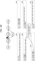
FIG. 27 is a diagram (1) for explaining a process at the time of transmission cancellation; -
FIG. 28 is a diagram (2) for explaining the process at the time of transmission cancellation; -
FIG. 29 is a diagram (3) for explaining the process at the time of transmission cancellation; -
FIG. 30 is a diagram (4) for explaining the process at the time of transmission cancellation; -
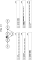
FIG. 31 is a diagram (5) for explaining the process at the time of transmission cancellation; -
FIG. 32 is a diagram (6) for explaining the process at the time of transmission cancellation; -
FIG. 33 is a diagram (7) for explaining the process at the time of transmission cancellation; -
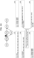
FIG. 34 is a diagram (8) for explaining the process at the time of transmission cancellation; -
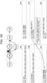
FIG. 35 is a diagram (9) for explaining the process at the time of transmission cancellation; -
FIG. 36 is a diagram (10) for explaining the process at the time of transmission cancellation; -
FIG. 37 is a diagram (11) for explaining the process at the time of transmission cancellation; -
FIG. 38 is a diagram (12) for explaining the process at the time of transmission cancellation; -
FIG. 39 is a diagram (13) for explaining the process at the time of transmission cancellation; -
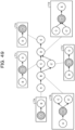
FIG. 40 is a diagram (14) for explaining the process at the time of transmission cancellation; -
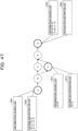
FIG. 41 is a diagram (15) for explaining the process at the time of transmission cancellation; -
FIG. 42 is a diagram (16) for explaining the process at the time of transmission cancellation; -
FIG. 43 is a functional block diagram illustrating a node configuration according to the present embodiment; -
FIG. 44 is a diagram illustrating an exemplary data structure of management information; -
FIG. 45 is a diagram illustrating an exemplary hardware configuration of a computer that implements functions similar to those of the node according to the embodiment; -
FIG. 46 is a diagram for explaining nth-order transmission; -
FIG. 47 is a diagram (1) for explaining a function needed in the nth-order transmission; -
FIG. 48 is a diagram (2) for explaining the function needed in the nth-order transmission; and -
FIG. 49 is a diagram for explaining a problem of an existing technique. - Hereinafter, an embodiment of a control system, a control device, a control method, and a control program disclosed in the present application will be described in detail with reference to the drawings. Note that the disclosure is not limited by the embodiment.
- An exemplary control system according to the present embodiment will be described.
FIG. 1 is a diagram illustrating the control system according to the present embodiment. As illustrated inFIG. 1 , the control system includesnodes nodes 100A to 100E transmits and receives data in an autonomously distributed manner to carry out nth-order transmission. The most upstream node is assumed to be thenode 100A, and the most downstream node is assumed to be thenode 100E. Thenodes 100A to 100E are examples of a "control device". - A
node 100i (i = A to E) hasmanagement information 50i, and themanagement information 50i stores a distribution source list srci (may be referred to as "srci", "src_i", or the like) and a distribution destination list dsti (may be referred to as "dsti", "dst_i", or the like). The distribution source list srci is a set of lists of nodes that have been passed through from the mostupstream node 100A to thenode 100i. The distribution destination list dsti is a set of lists of nodes to be passed through from thenode 100i to the mostdownstream node 100E. An initial value of the distribution source list srci and the distribution destination list dsti is an empty set ϕ. - It is assumed that an adjacent node to which the
node 100i transmits data is determined in advance by an organization that manages thenode 100i. - For example, the
node 100A is coupled to thenode 100B, and transmits data to thenode 100B. Thenode 100A hasmanagement information 50A. Themanagement information 50A stores a distribution source list srcA (may be referred to as "srcA", "src_A", or the like) and a distribution destination list dstA (may be referred to as "dstA", "dst_A", or the like). - The
node 100B is coupled to thenodes node 100C or to thenode 100C'. Thenode 100B hasmanagement information 50B. Themanagement information 50B stores a distribution source list srcB (may be referred to as "srcB", "src_B", or the like) and a distribution destination list dstB (may be referred to as "dstB", "dst_B", or the like) - The
node 100C is coupled to thenodes node 100D. Thenode 100C hasmanagement information 50C. Themanagement information 50C stores a distribution source list srcc (may be referred to as "srcC", "src_C", or the like) and a distribution destination list dstC (may be referred to as "dstC", "dst_C", or the like). - The
node 100C' is coupled to thenodes node 100D. Thenode 100C' hasmanagement information 50C'. Themanagement information 50C' stores a distribution source list srcC' (may be referred to as "srcC'", "src_C'", or the like) and a distribution destination list dstC, (may be referred to as "dstC'", "dst_C'", or the like) - The
node 100D is coupled to thenodes node 100E. Thenode 100D hasmanagement information 50D. Themanagement information 50D stores a distribution source list srcD (may be referred to as "srcD", "src_D", or the like) and a distribution destination list dstD (may be referred to as "dstD", "dst_D", or the like). - The
node 100E is coupled to thenode 100D. Thenode 100E hasmanagement information 50E. Themanagement information 50E stores a distribution source list srcE (may be referred to as "srcE", "src_E", or the like) and a distribution destination list dstE (may be referred to as "dstE", "dst_E", or the like). - Here, a node updates its own management information at the time of data transmission and reception, and transmits an update request of another piece of management information to another node. The node that has received the update request of the management information updates the management information, and transmits an update request of management information to still another node when a specific condition is satisfied.
- First, an exemplary processing procedure at the time of transmission of the
node 100i will be described. InFIGs. 2 and3 to be described below, data transmission (Forward) from the upstream side to the downstream side will be described.FIG. 2 is a flowchart (1) illustrating the processing procedure (Forward) at the time of transmission. InFIG. 2 , a case where thenode 100i transmits data to anode 100j will be described. - As illustrated in
FIG. 2 , thenode 100i transmits an update request (srci) to thenode 100j (step S101). Thenode 100i stands by until receiving an update completion response (dstj) from thenode 100j (step S102). It is noted that the "update request (srci)" means to be an update request including the distribution source list srci of thenode 100i, and that the "update completion response (dstj)" means to be a completion response including the distribution destination list dstj of thenode 100j. - If the
node 100i fails to receive the update completion response (No in step S103), the process proceeds to step S102. If thenode 100i has received the update completion response (Yes in step S103), the process proceeds to step S104. - The
node 100i adds, to the distribution destination list dsti, "individual elements of dstj with thenode 100j added to the top thereof" (step S104). Thereby, identification information of thenode 100j and each element included in the dstj are added to the distribution destination list dsti of thenode 100i. -
FIG. 3 is a flowchart (2) illustrating the processing procedure (Forward) at the time of transmission.FIG. 3 illustrates a processing procedure of a node 100y in a case where an update request is transmitted from anode 100x to the node 100y. Thenode 100x is any one node of thenodes 100A to 100E. The node y is any one node of thenodes 100A to 100E that has received the update request from the node x. - The node 100y adds, to the distribution source list srcy, "individual elements of srcx with the
node 100x added to the end thereof"(step S110). Thereby, identification information of thenode 100x and each element included in the srcx are added to the distribution source list srcy of the node 100y. The node 100y determines whether or not a condition of dsty = {ϕ} is satisfied (step S111). If the condition of dsty = {ϕ} is satisfied (Yes in step S111), the node 100y transmits an update completion response (dsty) to thenode 100x (step S112). - On the other hand, if the condition of dsty = {ϕ} is not satisfied (No in step S111), the node 100y proceeds to step S113. The node 100y transmits the update request (srcy) to a
node 100z (which may be a plurality of nodes) at the top of individual elements of dsty (step S113). - The node 100y stands by until receiving an update completion response (dstz) from the
node 100z (step S114). If the node 100y has not received the update completion response from all thenodes 100z (No in step S115), the process proceeds to step S114. - If the node 100y has received the update completion response from all the
nodes 100z (Yes in step S115), the process proceeds to step S116. The node 100y adds "individual elements of dstz with thenode 100z added to the top thereof" to dsty (step S116), and the process proceeds to step S112. - The node 100y recursively executes the process when the update request is received, which has been described with reference to
FIG. 3 , until dsty becomes an empty set. - In
FIGs. 4 and5 to be described below, data transmission (Backward) from the upstream side to the downstream side will be described.FIG. 4 is a flowchart (1) illustrating the processing procedure (Backward) at the time of transmission. InFIG. 4 , a case where thenode 100i transmits data to thenode 100j will be described. - As illustrated in
FIG. 4 , thenode 100i transmits an update request to anode 100h (which may be a plurality of nodes) at the end of individual elements of srci (step S201). Thenode 100i stands by until receiving an update completion response from thenode 100h (step S202). - If the
node 100i has not received the update completion response from all thenodes 100h (No in step S203), the process proceeds to step S202. - If the
node 100i has received the update completion response from all thenodes 100h (Yes in step S203), the process is terminated. -
FIG. 5 is a flowchart (2) illustrating the processing procedure (Backward) at the time of transmission.FIG. 5 illustrates a processing procedure of the node 100y in a case where an update request is transmitted from thenode 100z to the node 100y. - The node 100y adds "individual elements of dstz with the
node 100z added to the end thereof" to dsty (step S210). The node 100y determines whether or not the condition of dsty = {ϕ} is satisfied (step S211). If the condition of dsty = {ϕ} is satisfied (Yes in step S211), the node 100y transmits an update completion response to thenode 100z (step S212). - The node 100y transmits the update request to the
node 100x (which may be a plurality of nodes) at the end of individual elements of srcy (step S213). The node 100y stands by until receiving an update completion response from thenode 100x (step S214). - If the node 100y has not received the update completion response from all the
nodes 100x (No in step S215), the process proceeds to step S214. If the node 100y has received the update completion response from all thenodes 100x (Yes in step S215), the process proceeds to step S212. - The node 100y recursively executes the process when the update request is received, which has been described with reference to
FIG. 5 , until dsty becomes an empty set. - Next, an exemplary process will be described in which the
node 100i executes the processes illustrated inFIGs. 2 to 5 and updates themanagement information 50i.FIGs. 6 to 23 are diagrams for explaining a process at the time of node transmission. -
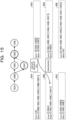
FIG. 6 will be described. As a premise, the distribution source list of themanagement information 50A of thenode 100A is assumed to be "srcA = {ϕ}", and the distribution destination list is assumed to be "dstA = {[100B, 100C, 100D, 100E], [100B, 100C']}". - The distribution source list of the
management information 50B of thenode 100B is assumed to be "srcB = {[100A]}", and the distribution destination list is assumed to be "dstB = {[100C, 100D, 100E], [100C']}". - The distribution source list of the
management information 50C of thenode 100C is assumed to be "srcC = {[100A, 100B]}", and the distribution destination list is assumed to be "dstC = {[100D, 100E]}". - The distribution source list of the
management information 50C' of thenode 100C' is assumed to be "srcC' = {[100A, 100B]}", and the distribution destination list is assumed to be "dstC' = {ϕ}". - The distribution source list of the
management information 50D of thenode 100D is assumed to be "srcD = {[100A, 100B, 100C]}", and the distribution destination list is assumed to be "dstD = {[100E]}". - The distribution source list of the
management information 50E of thenode 100E is assumed to be "srcD = {[100A, 100B, 100C, 100D]}", and the distribution destination list is assumed to be "dstD = {ϕ}". - The description proceeds to
FIG. 7 . The node 100C'transmits an update request "srcC'" to thenode 100D. - The description proceeds to
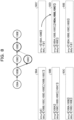
FIG. 8 . Upon reception of the update request "srcC"', thenode 100D merges "100A, 100B, 100C'" obtained by adding "100C'" to the end of individual elements of srcC' with srcD. As a result, the distribution source list of thenode 100D becomes "srcD = {[100A, 100B, 100C], [100A, 100B, 100C']}". - The description proceeds to
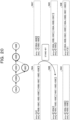
FIG. 9 . Thenode 100D transmits an update request "srcD" to the node at the top of individual elements of dstD. In the example illustrated inFIG. 9 , thenode 100D transmits the update request "srcD" to thenode 100E. - The description proceeds to
FIG. 10 . Upon reception of the update request "srcD", thenode 100E merges "100A, 100B, 100C', 100D" obtained by adding "100D" to the end of individual elements of srcD with srcE. As a result, the distribution source list of thenode 100E becomes "srcE = {[100A, 100B, 100C, 100D], [100A, 100B, 100C', 100D]}". - The description proceeds to
FIG. 11 . Since the distribution destination list is "dstE = {ϕ}", thenode 100E transmits an update completion response "dstE" to thenode 100D. - The description proceeds to
FIG. 12 . Upon reception of the update completion response "dstE", thenode 100D merges [E] obtained by adding 100E to the top of individual elements of dstE with dstD. As a result, the distribution destination list of thenode 100D becomes "dstD = {[100E]}". Note that thenode 100D stands by until receiving the update completion response for all the transmitted update requests. - The description proceeds to
FIG. 13 . Thenode 100D transmits an update completion response "dstd" to thenode 100C'. - The description proceeds to
FIG. 14 . Upon reception of the update completion response "dstD", thenode 100C' merges "D, E" obtained by adding thenode 100D to the top of the individual elements of dstD with dstC'. As a result, the distribution destination list of thenode 100C' becomes "dstC' = {[100D, 100E]}". - The description proceeds to
FIG. 15 . The node 100C'transmits an update request "dstC'" to the node at the end of the individual elements of the distribution source list srcC'. In the example ofFIG. 15 , thenode 100C' transmits the update request "dstC'" to thenode 100B. - The description proceeds to
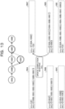
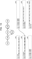
FIG. 16 . Upon reception of the update request "dstC"', thenode 100B merges "100C', 100D, 100E" obtained by adding 100C' to the top of the individual elements of dstC' with dstB. As a result, the distribution destination list of thenode 100B becomes "dstB = {[100C, 100D, 100E], [100C', 100D, 100E]}". - The description proceeds to
FIG. 17 . Thenode 100B transmits an update request "dstB" to the node at the end of the individual elements of the distribution source list srcB. In the example ofFIG. 17 , thenode 100B transmits the update request "dstB" to thenode 100A. - The description proceeds to
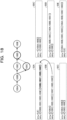
FIG. 18 . Upon reception of the update request "dstB", thenode 100A merges "100B, 100C', 100D, 100E" obtained by adding 100B to the top of the individual elements of dstB with dstA. As a result, the distribution destination list of thenode 100A becomes "dstA = {[100B, 100C, 100D, 100E], [100B, 100C', 100D, 100E]}". - The description proceeds to
FIG. 19 . Since the distribution source list is "srcA = {ϕ}", thenode 100A transmits an update completion response to thenode 100B. - The description proceeds to
FIG. 20 . Thenode 100B receives the update completion response. Thenode 100B stands by until receiving the update completion response for all the transmitted update requests. - The description proceeds to
FIG. 21 . Thenode 100B transmits an update completion response to thenode 100C'. - The description proceeds to
FIG. 22 . Thenode 100C' receives the update completion response. Thenode 100C' stands by until receiving the update completion response for all the transmitted update requests. - The description proceeds to
FIG. 23 . When the series of processes by thenode 100C' transmitting the update request "srcC'" to thenode 100D is complete, themanagement information 50A to 50E retain the information illustrated inFIG. 23 . As a result, thenode 100i is enabled to correctly grasp the data distribution source and the data distribution destination. - Next, an exemplary processing procedure at the time of transmission cancellation by the
node 100i will be described.FIGs. 24 to 26 are flowcharts illustrating the processing procedure at the time of transmission cancellation by the node. -
FIG. 24 will be described. InFIG. 24 , a case where thenode 100i transmits data (spath) related to transmission cancellation to thenode 100j will be described. Thenode 100i defines as spath, "individual elements of srci with the 100i added to the end thereof"(step S301). Thenode 100i transmits a "src cancellation request" (spath) to thenode 100j (step S302). It is noted that the "src cancellation request (spath)" means to be a cancellation request including the data "spath". - The
node 100i stands by until receiving a cancellation completion response from thenode 100j (step S303). If thenode 100i fails the receive the cancellation completion response (No in step S304), the process proceeds to step S303. - On the other hand, if the
node 100i has received the cancellation completion response (Yes in step S304), the process proceeds to step S305. Thenode 100i defines as dpath, "individual elements of spath received from thenode 100j with a portion matching the individual elements of srci removed from the top thereof" (step S305). - The
node 100i transmits a dst cancellation request (dpath) to thenode 100h at the end of the individual elements of srci (step S306). It is noted that the "dst cancellation request (dpath)" means to be a cancellation request including the data "dpath". Thenode 100i stands by until receiving a cancellation completion response from thenode 100h (step S307). If thenode 100i has not received the cancellation completion response from all thenodes 100h (No in step S308), the process proceeds to step S307. - On the other hand, if the
node 100i has received the cancellation completion response (dpath) from all thenodes 100h (Yes in step S308), the process proceeds to step S309. Thenode 100i removes 100i from the top of the individual elements of dpath received from thenode 100h (step S309). Thenode 100i removes, from dsti, an element matching the element of dpath (step S310). -
FIG. 25 will be described.FIG. 25 illustrates a processing procedure of the node 100y in a case where a cancellation request is transmitted from thenode 100x to the node 100y. - The node 100y receives spath (cancellation request) from the
node 100x (step S401). The node 100y removes, from srcy, an element matching the element of spath (step S402). - The node 100y adds 100y to the end of the individual elements of spath (step S403). The node 100y determines whether or not the condition of dsty = {ϕ} is satisfied (step S404). If the condition of dsty = {ϕ} is satisfied (Yes in step S404), the node 100y proceeds to step S410.
- On the other hand, if the condition of dsty = {ϕ} is not satisfied (No in step S404), the node 100y proceeds to step S405. The node 100y transmits a src cancellation request (spath) to the
node 100z at the top of the individual elements of dsty (step S405). - The node 100y stands by until receiving a cancellation completion response from the
node 100z (step S406). If the node 100y has not received the cancellation completion response from all thenodes 100z (No in step S407), the process proceeds to step S406. - On the other hand, if the node 100y has received the cancellation completion response from all the
nodes 100z (Yes in step S407), the process proceeds to step S408. The node 100y determines whether or not a condition of srcy = {ϕ} is satisfied (step S408). If the condition of srcy = {ϕ} is not satisfied (No in step S408), the node 100y proceeds to step S410. - On the other hand, if the condition of srcy = {ϕ} is satisfied (Yes in step S408), the node 100y deletes the element of dsty (step S409). The node 100y transmits a cancellation completion response (spath) to the
node 100x (step S410). -
FIG. 26 will be described.FIG. 26 illustrates a processing procedure of the node 100y in a case where a dst cancellation request (dpath) is transmitted from thenode 100z to the node 100y. - The node 100y receives dpath from the
node 100z (step S501). The node 100y adds 100y to the top of the individual elements of dpath (step S502). - The node 100y determines whether or not the condition of srcy = {ϕ} is satisfied (step S503). If the condition of srcy = {ϕ} is satisfied (Yes in step S503), the node 100y proceeds to step S507.
- On the other hand, if the condition of srcy = {ϕ} is not satisfied (No in step S503), the node 100y transmits the dst cancellation request (dpath) to the
node 100x at the end of the individual elements of srcy (step S504). - The node 100y stands by until receiving a cancellation completion response from the
node 100x (step S505). If the node 100y has not received the cancellation completion response from all thenodes 100x (No in step S506), the process proceeds to step S505. - On the other hand, if the node 100y has received the cancellation completion response from all the
nodes 100x (Yes in step S506), the process proceeds to step S507. The node 100y deletes 100y from the top of the individual elements of dpath (step S507). - The node 100y deletes, from dsty, an element matching the element of dpath (step S508). The node 100y transmits a cancellation completion response (dpath) to the
node 100z (step S509). - Next, an exemplary process in which, when transmission cancellation is transmitted, the
node 100i executes the processes illustrated inFIGs. 24 to 26 and updates themanagement information 50i will be described.FIGs. 27 to 42 are diagrams for explaining the process at the time of transmission cancellation. -
FIG. 27 will be described. As a premise, the distribution source list of themanagement information 50A of thenode 100A is assumed to be "srcA = {ϕ}", and the distribution destination list is assumed to be "dstA = {[100B, 100C, 100D, 100E], [100B, 100C', 100D, 100E]}". - The distribution source list of the
management information 50B of thenode 100B is assumed to be "srcB = {[100A]}", and the distribution destination list is assumed to be "dstB = {[100C, 100D, 100E], [100C', 100D, 100E]}". - The distribution source list of the
management information 50C of thenode 100C is assumed to be "srcC = {[100A, 100B]}", and the distribution destination list is assumed to be "dstC = {[100D, 100E]}". - The distribution source list of the
management information 50C' of thenode 100C' is assumed to be "srcC' = {[100A, 100B]}", and the distribution destination list is assumed to be "dstC' = {[100D, 100E]}". - The distribution source list of the
management information 50D of thenode 100D is assumed to be "srcD = {[100A, 100B, 100C], [100A, 100B, 100C']}", and the distribution destination list is assumed to be "dstD = {[100E]}". - The distribution source list of the
management information 50E of thenode 100E is assumed to be "srcD = {[100A, 100B, 100C, 100D], [100A, 100B, 100C', 100D]}", and the distribution destination list is assumed to be "dstD = {ϕ}". - The description proceeds to
FIG. 28 . Thenode 100B performs the following process in a case of canceling data transmission from thenode 100B to thenode 100C. Thenode 100B defines spath = [100A, 100B] obtained by adding 100B to the end of the individual elements of srcB. Thenode 100B transmits a cancellation request "spath = [100A, 100B]" to thenode 100C. - The description proceeds to
FIG. 29 . Upon reception of the cancellation request, thenode 100C deletes spath = [100A, 100B] from srcC. - The description proceeds to
FIG. 30 . Thenode 100C defines spath = [100A, 100B, 100C] obtained by adding 100C to the end of the individual elements of spath. Thenode 100C transmits a cancellation request "spath = [100A, 100B, 100C]" to thenode 100D. - The description proceeds to
FIG. 31 . Upon reception of the cancellation request, thenode 100D deletes spath = [100A, 100B, 100C] from srcD. - The description proceeds to
FIG. 32 . Thenode 100D defines spath = [100A, 100B, 100C, 100D] obtained by adding 100D to the end of the individual elements of spath. Thenode 100D transmits a cancellation request "spath = [100A, 100B, 100C, 100D]" to thenode 100E. - The description proceeds to
FIG. 33 . Upon reception of the cancellation request, thenode 100E deletes spath = [100A, 100B, 100C, 100D] from srcE. - The description proceeds to
FIG. 34 . Thenode 100E defines spath = [100A, 100B, 100C, 100D, 100E] obtained by adding 100E to the end of the individual elements of spath. Since dstE is an empty set, thenode 100E transmits a cancellation completion response "spath = [100A, 100B, 100C, 100D, 100E]" to thenode 100D. - The description proceeds to
FIG. 35 . Upon reception of the cancellation completion response "spath = [100A, 100B, 100C, 100D, 100E]", thenode 100D transmits the cancellation completion response to thenode 100C. - The description proceeds to
FIG. 36 . Upon reception of the cancellation completion response "spath = [100A, 100B, 100C, 100D, 100E]", thenode 100C deletes the element from dstC. - The description proceeds to
FIG. 37 . Thenode 100C transmits the cancellation completion response "spath = [100A, 100B, 100C, 100D, 100E]" to thenode 100B. - The description proceeds to
FIG. 38 . Upon reception of the cancellation completion response "spath = [100A, 100B, 100C, 100D, 100E]", thenode 100B defines, as dpath, a set of elements obtained by removing srcB from the top of the individual elements of spath. Thenode 100B transmits a cancellation request "dpath = [100B, 100C, 100D, 100E]" to thenode 100A. - The description proceeds to
FIG. 39 . Upon reception of the cancellation request "dpath = [100B, 100C, 100D, 100E]", thenode 100A deletes dpath = [100B, 100C, 100D, 100E] from dstA. - Here, although illustration is omitted in
FIG. 39 , in a case other than srcA = {ϕ}, thenode 100A performs the following process. Thenode 100A transmits a cancellation request "dpath = [100A, 100B, 100C, 100D, 100E]" obtained by adding 100A to the top of the individual elements of dpath to the node at the end of srcA. If a cancellation completion response is returned from the node at the end of srcA, thenode 100A deletes 100A from the top of dpath, and deletes dpath from dstA. - The description proceeds to
FIG. 40 . Since srcA = {ϕ} is satisfied, thenode 100A transmits a cancellation completion response "dpath = [100B, 100C, 100D, 100E]" to thenode 100B. - The description proceeds to
FIG. 41 . Upon reception of the cancellation completion response "dpath = [100B, 100C, 100D, 100E]", thenode 100B defines dpath = [100C, 100D, 100E] obtained by removing 100B from the top of the individual elements of dpath. Thenode 100B removes dpath = [100C, 100D, 100E] from dstB. - The description proceeds to
FIG. 42 . When the series of processes by thenode 100B canceling the data transmission to thenode 100C, themanagement information FIG. 42 . As a result, thenode 100i is enabled to appropriately update the distribution source list and the distribution destination list when data transmission cancellation occurs. - Next, an exemplary configuration of the
node 100i according to the present embodiment that performs the processes described above will be described. Thenode 100i corresponds to any one node of thenodes 100A to 100E illustrated inFIG. 1 and the like.FIG. 43 is a functional block diagram illustrating a node configuration according to the present embodiment. As illustrated inFIG. 43 , thenode 100i includes acommunication unit 110, aninput unit 120, adisplay unit 130, astorage unit 140, and acontrol unit 150. - The
communication unit 110 executes data communication with an external device and the like via a network. Thecontrol unit 150 to be described later exchanges data with an external device via thecommunication unit 110. - The
input unit 120 is an input device that inputs various types of information to thecontrol unit 150 of thenode 100i. Theinput unit 120 corresponds to a keyboard, a mouse, a touch panel, or the like. - The
display unit 130 is a display device that displays information output from thecontrol unit 150. - The
storage unit 140 has themanagement information 50i. Thestorage unit 140 corresponds to a semiconductor memory element such as a random access memory (RAM) or a flash memory, or a storage device such as a hard disk drive (HDD). - The
management information 50i stores the distribution source list srci and the distribution destination list dsti.FIG. 44 is a diagram illustrating an exemplary data structure of the management information. As illustrated inFIG. 44 , themanagement information 50i associates data ID, the distribution source list srci, and the distribution destination list dsti. - The data ID is an identification number assigned to each data to be subject to the nth-order transmission, and is used to identify the distribution source list srci and the distribution destination list dsti of each node. For example, each of the individual distribution source lists srci and distribution destination lists dsti illustrated in
FIGs. 6 to 23 andFIGs. 27 to 42 is associated with the same data ID. - The distribution source list srci is a set of lists of nodes that have been passed through from the most upstream node (e.g.,
node 100A) to thenode 100i. The distribution destination list dsti is a set of lists of nodes to be passed through from thenode 100i to the most downstream node (e.g.,node 100E). - The
control unit 150 includes a firsttransmission control unit 151 and a secondtransmission control unit 152. Thecontrol unit 150 is implemented by a central processing unit (CPU), a graphics processing unit (GPU), a hard-wired logic such as an application specific integrated circuit (ASIC) or a field programmable gate array (FPGA), or the like. - The first
transmission control unit 151 executes the data transmission (Forward) from the upstream side to the downstream side described with reference toFIGs. 2 and3 . Furthermore, the firsttransmission control unit 151 executes the data transmission (Backward) from the downstream side to the upstream side described with reference toFIGs. 4 and5 . With the firsttransmission control unit 151 of each of thenodes 100A to 100E executing the processes ofFIGs. 2 to 5 , data of themanagement information 50A to 50E becomes the data illustrated inFIG. 23 , whereby thenodes 100A to 100E are enabled to correctly grasp the data distribution source and the data distribution destination. - For example, in a case where the first
transmission control unit 151 receives an update request in which a distribution source list of the upstream adjacent node is set, it updates the distribution source list based on the update request, generates a new update request based on the updated distribution source list, and transmits the new update request to the downstream adjacent node. - In a case where the first
transmission control unit 151 receives an update completion response in which a distribution destination list of the downstream adjacent node is set, it updates the distribution destination list based on the update completion response. Note that, in a case where the distribution destination list is an empty set, the firsttransmission control unit 151 transmits an update completion response to the upstream adjacent node. - Other specific processing procedures related to the first
transmission control unit 151 correspond to the processing procedures illustrated inFIGs. 2 to 5 . - The second
transmission control unit 152 executes the processes at the time of transmission cancellation described with reference toFIGs. 24 to 26 . With the secondtransmission control unit 152 of each of thenodes 100A to 100E executing the processes ofFIGs. 24 to 26 , data of themanagement information 50A to 50E becomes the data illustrated inFIG. 42 , whereby the distribution source list and the distribution destination list may be appropriately updated when data transmission cancellation occurs. - For example, in a case where the second
transmission control unit 152 receives a cancellation request, it deletes the identification information list of the node of the cancellation request from the distribution source list, generates a new cancellation request in which the identification information of its own node is set at the end of the cancellation request list, and transmits the new cancellation request to a downstream node. - In a case where the distribution destination list of its own node is not an empty set, the second
transmission control unit 152 transmits the new cancellation request to the downstream adjacent node. In a case where the distribution destination list of its own node is an empty set, the secondtransmission control unit 152 transmits, to the upstream adjacent node, a cancellation completion response in which the identification information of its own node is set at the end of the cancellation request list. - In a case where the second
transmission control unit 152 receives a cancellation completion response from the downstream adjacent node and the distribution source list of its own node is an empty set, it sets (deletes) the distribution destination list of its own node to an empty set. - Other specific processing procedures related to the second
transmission control unit 152 correspond to the processing procedures illustrated inFIGs. 24 to 26 . - Next, effects of the control system according to the present embodiment will be described. In a case where the
node 100i of the control system receives an update request in which a distribution source list of the upstream adjacent node is set, it updates the distribution source list based on the update request, generates a new update request based on the updated distribution source list, and transmits the new update request to the downstream adjacent node. In a case where thenode 100i receives an update completion response in which a distribution destination list of the downstream adjacent node is set, it updates the distribution destination list based on the update completion response. In a case where the distribution destination list is an empty set, thenode 100i transmits an update completion response to the upstream adjacent node. As a result, thenode 100i is enabled to correctly grasp the data distribution source and the data distribution destination. - In a case where the
node 100i of the control system receives a cancellation request, it deletes the identification information list of the node of the cancellation request from the distribution source list, generates a new cancellation request in which the identification information of its own node is set at the end of the cancellation request list, and transmits the new cancellation request to a downstream node. In a case where the distribution destination list of its own node is not an empty set, thenode 100i transmits the new cancellation request to the downstream adjacent node. In a case where the distribution destination list of its own node is an empty set, thenode 100i transmits, to the upstream adjacent node, a cancellation completion response in which the identification information of its own node is set at the end of the cancellation request list. In a case where thenode 100i receives a cancellation completion response from the downstream adjacent node and the distribution source list of its own node is an empty set, it deletes the distribution destination list of its own node. As a result, it becomes possible to appropriately update the distribution source list and the distribution destination list when data transmission cancellation occurs. - Next, an exemplary hardware configuration of a computer that implements functions similar to those of the
node 100i described above will be described.FIG. 45 is a diagram illustrating an exemplary hardware configuration of the computer that implements functions similar to those of the node according to the embodiment. - As illustrated in
FIG. 45 , acomputer 200 includes aCPU 201 that executes various types of arithmetic processing, aninput device 202 that receives data input from a user, and adisplay 203. Furthermore, thecomputer 200 includes acommunication device 204 that exchanges data with another node, an external device, and the like via a wired or wireless network, and aninterface device 205. Furthermore, thecomputer 200 includes aRAM 206 that temporarily stores various types of information, and ahard disk device 207. Additionally, each of thedevices 201 to 207 is coupled to a bus 208. - The
hard disk device 207 has a firsttransmission control program 207a and a secondtransmission control program 207b. Furthermore, theCPU 201 reads each of theprograms RAM 206. - The first
transmission control program 207a functions as a firsttransmission control process 206a. The secondtransmission control program 207b functions as a secondtransmission control process 206b. - Processing of the first
transmission control process 206a corresponds to the processing of the firsttransmission control unit 151. Processing of the secondtransmission control process 206b corresponds to the processing of the secondtransmission control unit 152. - Note that each of the
programs hard disk device 207 beforehand. For example, each of the programs may be stored in a "portable physical medium" to be inserted into thecomputer 200, such as a flexible disk (FD), a compact disc read only memory (CD-ROM), a digital versatile disc (DVD), a magneto-optical disk, or an integrated circuit (IC) card. Then, thecomputer 200 may read and execute each of theprograms
Claims (8)
- A control system comprising a plurality of control devices configured to perform nth-order transmission, wherein each control device of the plurality of control devices includes:a storage unit that stores, in relation to the plurality of control devices, a distribution source list that stores a list of the plurality of control devices to be passed through from a most upstream control device to the plurality of control device and a distribution destination list that stores a list of the plurality of control devices to be passed through from the control device to a most downstream control device; anda control unit configured to perform control processing including:
in a case where an update request in which a first distribution source list of a first control device being any one of the plurality of control devices is set is received,updating the distribution source list based on the update request,generating a new update request based on the updated distribution source list, andtransmitting the new update request to a second control device being any one of the plurality of control devices other than the first control device; and
in a case where an update completion response in which a second distribution destination list of the second control device is set is received from the second control device, updating the distribution destination list based on the update completion response. - A control device comprising:a storage unit configured to store, in relation to a plurality of control devices that performs nth-order transmission, a distribution source list that stores a list of the plurality of control devices to be passed through from a most upstream control device to the control device and a distribution destination list that stores a list of the plurality of control devices to be passed through from the control device to a most downstream control device; anda control unit configured to perform control processing including:
in a case where an update request in which a first distribution source list of a first control device being any one of the plurality of control devices is set is received,updating the distribution source list based on the update request,generating a new update request based on the updated distribution source list, andtransmitting the new update request to a second control device being any one of the plurality of control devices other than the first control device; and
in a case where an update completion response in which a second distribution destination list of the second control device is set is received from the second control device, updating the distribution destination list based on the update completion response. - The control device according to claim 2, wherein the control processing further includes transmitting the update completion response to the first control device when the distribution destination list is an empty set.
- The control device according to claim 2, wherein
the control processing further includes:in a case where a cancellation request indicating a request to cancel data transmission from a third control device to the control device is received, deleting a control device identification information list included in the cancellation request from the distribution source list, the cancellation request including the control device identification information list in which identification information of the third control device is added to an end of a third distribution source list of the third control device, the third control device being any one of the plurality of control devices; andgenerating a new cancellation request in which identification information of the control device is set at an end of the list of the cancellation request, to transmit the generated new cancellation request to a fourth control device of the plurality of control devices other than the third control device. - The control device according to claim 4, wherein
the control processing further includes:transmitting the new cancellation request to the fourth control device in a case where the distribution destination list of the control device is not an empty set; andin a case where the distribution destination list of the control device is the empty set, transmitting, to the third control device, a cancellation completion response in which the identification information of the control device is set at the end of the list of the cancellation request. - The control device according to claim 5, wherein the control processing further includes:
deleting the distribution destination list of the control device when the cancellation completion response is received from the fourth control device and the distribution source list of the control device is the empty set. - A control method implemented by each control device of a plurality of control devices, the control device including a storage device configured to store, in relation to the plurality of control devices that performs nth-order transmission, a distribution source list that stores a list of the plurality of control devices to be passed through from a most upstream control device to the control device and a distribution destination list that stores a list of the control devices to be passed through from the control device to a most downstream control device, the control method comprising:in a case where an update request in which a first distribution source list of a first control device being any one of the plurality of control devices is set is received,updating the distribution source list based on the update request,generating a new update request based on the updated distribution source list, andtransmitting the new update request to a second control device being any one of the plurality of control devices other than the first control device; andin a case where an update completion response in which a second distribution destination list of the second control device is set is received from the second control device, updating the distribution destination list based on the update completion response.
- A control program comprising instructions which, when executed by each control device of a plurality of control devices, cause the control device to perform control processing, the control device including a storage device configured to store, in relation to the plurality of control devices that performs nth-order transmission, a distribution source list that stores a list of the plurality of control devices to be passed through from a most upstream control device to the control device and a distribution destination list that stores a list of the control devices to be passed through from the control device to a most downstream control device, the control processing comprising:in a case where an update request in which a first distribution source list of a first control device being any one of the plurality of control devices is set is received,updating the distribution source list based on the update request,generating a new update request based on the updated distribution source list, andtransmitting the new update request to a second control device being any one of the plurality of control devices other than the first control device; andin a case where an update completion response in which a second distribution destination list of the second control device is set is received from the second control device, updating the distribution destination list based on the update completion response.
Applications Claiming Priority (1)
| Application Number | Priority Date | Filing Date | Title |
|---|---|---|---|
| JP2022158456A JP2024052023A (en) | 2022-09-30 | 2022-09-30 | Control system, control device, control method, and control program |
Publications (2)
| Publication Number | Publication Date |
|---|---|
| EP4346188A1 true EP4346188A1 (en) | 2024-04-03 |
| EP4346188B1 EP4346188B1 (en) | 2025-09-17 |
Family
ID=87036902
Family Applications (1)
| Application Number | Title | Priority Date | Filing Date |
|---|---|---|---|
| EP23181725.5A Active EP4346188B1 (en) | 2022-09-30 | 2023-06-27 | Control device, control method, and control program using distribution source and destination lists |
Country Status (3)
| Country | Link |
|---|---|
| US (1) | US20240111262A1 (en) |
| EP (1) | EP4346188B1 (en) |
| JP (1) | JP2024052023A (en) |
Citations (4)
| Publication number | Priority date | Publication date | Assignee | Title |
|---|---|---|---|---|
| US20080031130A1 (en) * | 2006-08-01 | 2008-02-07 | Raj Alex E | Methods and apparatus for minimizing duplicate traffic during point to multipoint tree switching in a network |
| JP2018005301A (en) | 2016-06-27 | 2018-01-11 | 富士通株式会社 | Control device, transmission device, and download method |
| WO2018216206A1 (en) | 2017-05-26 | 2018-11-29 | 日本電気株式会社 | Data control system, data control method, and data control program |
| US20210067438A1 (en) * | 2019-08-29 | 2021-03-04 | Dell Products L.P. | Multicast transmissions management |
Family Cites Families (4)
| Publication number | Priority date | Publication date | Assignee | Title |
|---|---|---|---|---|
| JP4710889B2 (en) * | 2007-08-24 | 2011-06-29 | 日本電気株式会社 | Attack packet countermeasure system, attack packet countermeasure method, attack packet countermeasure apparatus, and attack packet countermeasure program |
| US11088937B1 (en) * | 2014-05-08 | 2021-08-10 | Google Llc | System and method for synchronized route update |
| EP3404550B1 (en) * | 2016-01-14 | 2020-06-17 | Fujitsu Limited | Server device, communication system, and communication program |
| JP7557817B2 (en) * | 2020-10-07 | 2024-09-30 | PicoCELA株式会社 | node |
-
2022
- 2022-09-30 JP JP2022158456A patent/JP2024052023A/en active Pending
-
2023
- 2023-06-21 US US18/338,544 patent/US20240111262A1/en active Pending
- 2023-06-27 EP EP23181725.5A patent/EP4346188B1/en active Active
Patent Citations (5)
| Publication number | Priority date | Publication date | Assignee | Title |
|---|---|---|---|---|
| US20080031130A1 (en) * | 2006-08-01 | 2008-02-07 | Raj Alex E | Methods and apparatus for minimizing duplicate traffic during point to multipoint tree switching in a network |
| JP2018005301A (en) | 2016-06-27 | 2018-01-11 | 富士通株式会社 | Control device, transmission device, and download method |
| WO2018216206A1 (en) | 2017-05-26 | 2018-11-29 | 日本電気株式会社 | Data control system, data control method, and data control program |
| US20200201990A1 (en) * | 2017-05-26 | 2020-06-25 | Nec Corporation | Data control system, data control method, and data control program |
| US20210067438A1 (en) * | 2019-08-29 | 2021-03-04 | Dell Products L.P. | Multicast transmissions management |
Also Published As
| Publication number | Publication date |
|---|---|
| JP2024052023A (en) | 2024-04-11 |
| EP4346188B1 (en) | 2025-09-17 |
| US20240111262A1 (en) | 2024-04-04 |
Similar Documents
| Publication | Publication Date | Title |
|---|---|---|
| US12393874B2 (en) | Data processing system and method | |
| JP7532633B2 (en) | Method, device, electronic device, and storage medium for updating cited documents | |
| CN109951547B (en) | Transaction request parallel processing method, device, equipment and medium | |
| US8136077B2 (en) | Timing-optimal placement, pin assignment, and routing for integrated circuits | |
| US9250987B2 (en) | Administering incomplete data communications messages in a parallel computer | |
| US20230095725A1 (en) | Method of processing quantum circuit, electronic device, and storage medium | |
| US20100106539A1 (en) | Method and system for fast local search and insertion heuristics for vehicle routing | |
| CN111798316B (en) | Parallel chain consensus method, apparatus and storage medium | |
| US9921874B2 (en) | Storage medium, information processing device, and information processing method | |
| US20230353458A1 (en) | Neural network computing-oriented modeling method and apparatus for distributed data routing | |
| US20240152458A1 (en) | Data caching method, system and device in ai cluster, and computer medium | |
| CN110798498B (en) | Method for managing data flow for edge-core distributed analytics systems | |
| CN112784187A (en) | Page display method and device | |
| CN110162761B (en) | Collaborative editing method, device and equipment for document and storage medium | |
| CN111309366B (en) | Method, device, medium and electronic equipment for managing registration core | |
| EP4346188B1 (en) | Control device, control method, and control program using distribution source and destination lists | |
| CN109901919B (en) | Information output method and device | |
| CN109254977A (en) | Data creation method, big data air control platform and computer storage medium | |
| JP2004326480A (en) | Distributed parallel analysis of large amounts of data | |
| CN109635238B (en) | Matrix operation method, device, equipment and readable medium | |
| CN113434089A (en) | Data moving method and device and PCIE system | |
| CN113095537A (en) | Path planning method and device | |
| US12566917B2 (en) | Server apparatus and client apparatus | |
| JP2006023948A (en) | Resource search method, cluster system, computer, and cluster | |
| CN116842938A (en) | Address information processing method and device, electronic equipment and storage medium |
Legal Events
| Date | Code | Title | Description |
|---|---|---|---|
| PUAI | Public reference made under article 153(3) epc to a published international application that has entered the european phase |
Free format text: ORIGINAL CODE: 0009012 |
|
| STAA | Information on the status of an ep patent application or granted ep patent |
Free format text: STATUS: THE APPLICATION HAS BEEN PUBLISHED |
|
| AK | Designated contracting states |
Kind code of ref document: A1 Designated state(s): AL AT BE BG CH CY CZ DE DK EE ES FI FR GB GR HR HU IE IS IT LI LT LU LV MC ME MK MT NL NO PL PT RO RS SE SI SK SM TR |
|
| STAA | Information on the status of an ep patent application or granted ep patent |
Free format text: STATUS: REQUEST FOR EXAMINATION WAS MADE |
|
| 17P | Request for examination filed |
Effective date: 20240606 |
|
| RBV | Designated contracting states (corrected) |
Designated state(s): AL AT BE BG CH CY CZ DE DK EE ES FI FR GB GR HR HU IE IS IT LI LT LU LV MC ME MK MT NL NO PL PT RO RS SE SI SK SM TR |
|
| GRAP | Despatch of communication of intention to grant a patent |
Free format text: ORIGINAL CODE: EPIDOSNIGR1 |
|
| STAA | Information on the status of an ep patent application or granted ep patent |
Free format text: STATUS: GRANT OF PATENT IS INTENDED |
|
| RIC1 | Information provided on ipc code assigned before grant |
Ipc: H04L 67/1042 20220101AFI20250414BHEP |
|
| INTG | Intention to grant announced |
Effective date: 20250512 |
|
| GRAS | Grant fee paid |
Free format text: ORIGINAL CODE: EPIDOSNIGR3 |
|
| GRAA | (expected) grant |
Free format text: ORIGINAL CODE: 0009210 |
|
| STAA | Information on the status of an ep patent application or granted ep patent |
Free format text: STATUS: THE PATENT HAS BEEN GRANTED |
|
| AK | Designated contracting states |
Kind code of ref document: B1 Designated state(s): AL AT BE BG CH CY CZ DE DK EE ES FI FR GB GR HR HU IE IS IT LI LT LU LV MC ME MK MT NL NO PL PT RO RS SE SI SK SM TR |
|
| REG | Reference to a national code |
Ref country code: GB Ref legal event code: FG4D |
|
| REG | Reference to a national code |
Ref country code: CH Ref legal event code: EP |
|
| REG | Reference to a national code |
Ref country code: IE Ref legal event code: FG4D |
|
| REG | Reference to a national code |
Ref country code: DE Ref legal event code: R096 Ref document number: 602023006711 Country of ref document: DE |
|
| REG | Reference to a national code |
Ref country code: CH Ref legal event code: R17 Free format text: ST27 STATUS EVENT CODE: U-0-0-R10-R17 (AS PROVIDED BY THE NATIONAL OFFICE) Effective date: 20251124 |
|
| PG25 | Lapsed in a contracting state [announced via postgrant information from national office to epo] |
Ref country code: NO Free format text: LAPSE BECAUSE OF FAILURE TO SUBMIT A TRANSLATION OF THE DESCRIPTION OR TO PAY THE FEE WITHIN THE PRESCRIBED TIME-LIMIT Effective date: 20251217 |
|
| REG | Reference to a national code |
Ref country code: LT Ref legal event code: MG9D |
|
| PG25 | Lapsed in a contracting state [announced via postgrant information from national office to epo] |
Ref country code: FI Free format text: LAPSE BECAUSE OF FAILURE TO SUBMIT A TRANSLATION OF THE DESCRIPTION OR TO PAY THE FEE WITHIN THE PRESCRIBED TIME-LIMIT Effective date: 20250917 |
|
| PG25 | Lapsed in a contracting state [announced via postgrant information from national office to epo] |
Ref country code: HR Free format text: LAPSE BECAUSE OF FAILURE TO SUBMIT A TRANSLATION OF THE DESCRIPTION OR TO PAY THE FEE WITHIN THE PRESCRIBED TIME-LIMIT Effective date: 20250917 |
|
| PG25 | Lapsed in a contracting state [announced via postgrant information from national office to epo] |
Ref country code: GR Free format text: LAPSE BECAUSE OF FAILURE TO SUBMIT A TRANSLATION OF THE DESCRIPTION OR TO PAY THE FEE WITHIN THE PRESCRIBED TIME-LIMIT Effective date: 20251218 |
|
| PG25 | Lapsed in a contracting state [announced via postgrant information from national office to epo] |
Ref country code: SE Free format text: LAPSE BECAUSE OF FAILURE TO SUBMIT A TRANSLATION OF THE DESCRIPTION OR TO PAY THE FEE WITHIN THE PRESCRIBED TIME-LIMIT Effective date: 20250917 |
|
| REG | Reference to a national code |
Ref country code: NL Ref legal event code: MP Effective date: 20250917 |
|
| PG25 | Lapsed in a contracting state [announced via postgrant information from national office to epo] |
Ref country code: LV Free format text: LAPSE BECAUSE OF FAILURE TO SUBMIT A TRANSLATION OF THE DESCRIPTION OR TO PAY THE FEE WITHIN THE PRESCRIBED TIME-LIMIT Effective date: 20250917 |
|
| PG25 | Lapsed in a contracting state [announced via postgrant information from national office to epo] |
Ref country code: BG Free format text: LAPSE BECAUSE OF FAILURE TO SUBMIT A TRANSLATION OF THE DESCRIPTION OR TO PAY THE FEE WITHIN THE PRESCRIBED TIME-LIMIT Effective date: 20250917 |
|
| PG25 | Lapsed in a contracting state [announced via postgrant information from national office to epo] |
Ref country code: RS Free format text: LAPSE BECAUSE OF FAILURE TO SUBMIT A TRANSLATION OF THE DESCRIPTION OR TO PAY THE FEE WITHIN THE PRESCRIBED TIME-LIMIT Effective date: 20251217 |
|
| PG25 | Lapsed in a contracting state [announced via postgrant information from national office to epo] |
Ref country code: NL Free format text: LAPSE BECAUSE OF FAILURE TO SUBMIT A TRANSLATION OF THE DESCRIPTION OR TO PAY THE FEE WITHIN THE PRESCRIBED TIME-LIMIT Effective date: 20250917 |
|
| REG | Reference to a national code |
Ref country code: AT Ref legal event code: MK05 Ref document number: 1839386 Country of ref document: AT Kind code of ref document: T Effective date: 20250917 |
|
| PG25 | Lapsed in a contracting state [announced via postgrant information from national office to epo] |
Ref country code: SM Free format text: LAPSE BECAUSE OF FAILURE TO SUBMIT A TRANSLATION OF THE DESCRIPTION OR TO PAY THE FEE WITHIN THE PRESCRIBED TIME-LIMIT Effective date: 20250917 |
|
| PG25 | Lapsed in a contracting state [announced via postgrant information from national office to epo] |
Ref country code: ES Free format text: LAPSE BECAUSE OF FAILURE TO SUBMIT A TRANSLATION OF THE DESCRIPTION OR TO PAY THE FEE WITHIN THE PRESCRIBED TIME-LIMIT Effective date: 20250917 |
|
| PG25 | Lapsed in a contracting state [announced via postgrant information from national office to epo] |
Ref country code: AT Free format text: LAPSE BECAUSE OF FAILURE TO SUBMIT A TRANSLATION OF THE DESCRIPTION OR TO PAY THE FEE WITHIN THE PRESCRIBED TIME-LIMIT Effective date: 20250917 |
|
| PG25 | Lapsed in a contracting state [announced via postgrant information from national office to epo] |
Ref country code: IT Free format text: LAPSE BECAUSE OF FAILURE TO SUBMIT A TRANSLATION OF THE DESCRIPTION OR TO PAY THE FEE WITHIN THE PRESCRIBED TIME-LIMIT Effective date: 20250917 |
|
| PG25 | Lapsed in a contracting state [announced via postgrant information from national office to epo] |
Ref country code: IS Free format text: LAPSE BECAUSE OF FAILURE TO SUBMIT A TRANSLATION OF THE DESCRIPTION OR TO PAY THE FEE WITHIN THE PRESCRIBED TIME-LIMIT Effective date: 20260117 |
|
| PG25 | Lapsed in a contracting state [announced via postgrant information from national office to epo] |
Ref country code: PT Free format text: LAPSE BECAUSE OF FAILURE TO SUBMIT A TRANSLATION OF THE DESCRIPTION OR TO PAY THE FEE WITHIN THE PRESCRIBED TIME-LIMIT Effective date: 20260119 Ref country code: CZ Free format text: LAPSE BECAUSE OF FAILURE TO SUBMIT A TRANSLATION OF THE DESCRIPTION OR TO PAY THE FEE WITHIN THE PRESCRIBED TIME-LIMIT Effective date: 20250917 |
|
| PG25 | Lapsed in a contracting state [announced via postgrant information from national office to epo] |
Ref country code: PL Free format text: LAPSE BECAUSE OF FAILURE TO SUBMIT A TRANSLATION OF THE DESCRIPTION OR TO PAY THE FEE WITHIN THE PRESCRIBED TIME-LIMIT Effective date: 20250917 |
|
| PG25 | Lapsed in a contracting state [announced via postgrant information from national office to epo] |
Ref country code: SK Free format text: LAPSE BECAUSE OF FAILURE TO SUBMIT A TRANSLATION OF THE DESCRIPTION OR TO PAY THE FEE WITHIN THE PRESCRIBED TIME-LIMIT Effective date: 20250917 Ref country code: EE Free format text: LAPSE BECAUSE OF FAILURE TO SUBMIT A TRANSLATION OF THE DESCRIPTION OR TO PAY THE FEE WITHIN THE PRESCRIBED TIME-LIMIT Effective date: 20250917 |