EP4346108A1 - Method and apparatus for transmitting an uplink signal based on doppler frequency variation - Google Patents
Method and apparatus for transmitting an uplink signal based on doppler frequency variation Download PDFInfo
- Publication number
- EP4346108A1 EP4346108A1 EP23168149.5A EP23168149A EP4346108A1 EP 4346108 A1 EP4346108 A1 EP 4346108A1 EP 23168149 A EP23168149 A EP 23168149A EP 4346108 A1 EP4346108 A1 EP 4346108A1
- Authority
- EP
- European Patent Office
- Prior art keywords
- uplink signal
- doppler frequency
- change rate
- pilot signal
- signal
- Prior art date
- Legal status (The legal status is an assumption and is not a legal conclusion. Google has not performed a legal analysis and makes no representation as to the accuracy of the status listed.)
- Granted
Links
Images

Classifications
-
- H—ELECTRICITY
- H04—ELECTRIC COMMUNICATION TECHNIQUE
- H04B—TRANSMISSION
- H04B1/00—Details of transmission systems, not covered by a single one of groups H04B3/00 - H04B13/00; Details of transmission systems not characterised by the medium used for transmission
- H04B1/69—Spread spectrum techniques
-
- H—ELECTRICITY
- H04—ELECTRIC COMMUNICATION TECHNIQUE
- H04L—TRANSMISSION OF DIGITAL INFORMATION, e.g. TELEGRAPHIC COMMUNICATION
- H04L27/00—Modulated-carrier systems
- H04L27/26—Systems using multi-frequency codes
- H04L27/2601—Multicarrier modulation systems
- H04L27/2602—Signal structure
- H04L27/261—Details of reference signals
- H04L27/2613—Structure of the reference signals
- H04L27/26134—Pilot insertion in the transmitter chain, e.g. pilot overlapping with data, insertion in time or frequency domain
-
- H—ELECTRICITY
- H04—ELECTRIC COMMUNICATION TECHNIQUE
- H04L—TRANSMISSION OF DIGITAL INFORMATION, e.g. TELEGRAPHIC COMMUNICATION
- H04L27/00—Modulated-carrier systems
- H04L27/10—Frequency-modulated carrier systems, i.e. using frequency-shift keying
- H04L27/103—Chirp modulation
-
- H—ELECTRICITY
- H04—ELECTRIC COMMUNICATION TECHNIQUE
- H04L—TRANSMISSION OF DIGITAL INFORMATION, e.g. TELEGRAPHIC COMMUNICATION
- H04L27/00—Modulated-carrier systems
- H04L27/26—Systems using multi-frequency codes
- H04L27/2601—Multicarrier modulation systems
- H04L27/2602—Signal structure
- H04L27/261—Details of reference signals
- H04L27/2613—Structure of the reference signals
- H04L27/26132—Structure of the reference signals using repetition
-
- H—ELECTRICITY
- H04—ELECTRIC COMMUNICATION TECHNIQUE
- H04L—TRANSMISSION OF DIGITAL INFORMATION, e.g. TELEGRAPHIC COMMUNICATION
- H04L5/00—Arrangements affording multiple use of the transmission path
- H04L5/003—Arrangements for allocating sub-channels of the transmission path
- H04L5/0048—Allocation of pilot signals, i.e. of signals known to the receiver
-
- H—ELECTRICITY
- H04—ELECTRIC COMMUNICATION TECHNIQUE
- H04B—TRANSMISSION
- H04B1/00—Details of transmission systems, not covered by a single one of groups H04B3/00 - H04B13/00; Details of transmission systems not characterised by the medium used for transmission
- H04B1/69—Spread spectrum techniques
- H04B2001/6912—Spread spectrum techniques using chirp
-
- H—ELECTRICITY
- H04—ELECTRIC COMMUNICATION TECHNIQUE
- H04B—TRANSMISSION
- H04B2201/00—Indexing scheme relating to details of transmission systems not covered by a single group of H04B3/00 - H04B13/00
- H04B2201/69—Orthogonal indexing scheme relating to spread spectrum techniques in general
- H04B2201/698—Orthogonal indexing scheme relating to spread spectrum techniques in general relating to Uplink
-
- H—ELECTRICITY
- H04—ELECTRIC COMMUNICATION TECHNIQUE
- H04L—TRANSMISSION OF DIGITAL INFORMATION, e.g. TELEGRAPHIC COMMUNICATION
- H04L5/00—Arrangements affording multiple use of the transmission path
- H04L5/003—Arrangements for allocating sub-channels of the transmission path
- H04L5/0058—Allocation criteria
- H04L5/006—Quality of the received signal, e.g. BER, SNR, water filling
-
- H—ELECTRICITY
- H04—ELECTRIC COMMUNICATION TECHNIQUE
- H04L—TRANSMISSION OF DIGITAL INFORMATION, e.g. TELEGRAPHIC COMMUNICATION
- H04L5/00—Arrangements affording multiple use of the transmission path
- H04L5/0091—Signalling for the administration of the divided path, e.g. signalling of configuration information
- H04L5/0094—Indication of how sub-channels of the path are allocated
Definitions
- the present disclosure relates to an apparatus and a method for transmitting an uplink signal based on a Doppler frequency change.
- IoT technology in the terrestrial network includes LoRa, Ingenu, NB-IoT, etc.
- IoT technology for high-speed mobile bodies is being studied based on IoT technology that is being serviced on the terrestrial network.
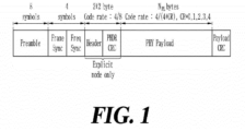
- the frame structure of the existing LoRa system is shown in FIG. 1 .
- the symbols of the frames of the LoRa system serviced through the terrestrial network are used for preamble (8 symbols), frame and frequency synchronizations (4.25 (2+2.25) symbols), header and cyclic redundancy check (CRC) for the header (4 bytes (4/8 Hamming code is used)), payload (NPL bytes), and CRC for the payload.
- CRC cyclic redundancy check
- a chirp spread spectrum modulation scheme is used for modulation of the preamble, synchronization, and payload symbol, and an extended Hamming code is used as an error correction code.
- the symbol modulation scheme of the LoRa is the chirp spread spectrum modulation scheme, and when a spreading factor, SF, is applied to the modulation scheme, one symbol includes 2SF number of continuous chips.
- the baseband frequency of the symbol continuously increases over time.
- reception performance may be significantly reduced due to a Doppler effect generated due to a large relative speed between the high-speed mobile body and the IoT terminal.
- One embodiment of the present disclosure provides an apparatus for transmitting a signal based on a Doppler frequency change.
- Another embodiment of the present disclosure provides a method of transmitting a signal based on a Doppler frequency change.
- an apparatus for transmitting an uplink signal to a base station includes a processor, a memory, and a communication unit, where the processor executes a program stored in the memory to perform the steps of: calculating a maximum change rate of a Doppler frequency; arranging a pilot signal in the uplink signal based on a spreading factor of the uplink signal and the maximum change rate of the Doppler frequency; and transmitting the uplink signal in which the pilot signal is arranged to the base station.
- the processor when performing the step of arranging the pilot signal in the uplink signal based on the spreading factor of the uplink signal and the maximum change rate of the Doppler frequency, the processor may perform a step of arranging the pilot signal between symbols of a payload of the uplink signal.
- the processor when performing the step of arranging the pilot signal between the symbols of the payload of the uplink signal, the processor may perform a step of periodically arranging the pilot signal between the symbols of the payload.
- the processor when performing the step of periodically arranging the pilot signal between the symbols of the payload, may perform a step of inserting information indicating that the pilot signal is present in the payload and information on a period of the pilot signal into a header of the uplink signal.
- the processor when performing the step of arranging the pilot signal in the uplink signal based on the spreading factor of the uplink signal and the maximum change rate of the Doppler frequency, the processor may perform the steps of: determining a frequency bandwidth of a chip based on a bandwidth of the uplink signal and the spreading factor; and determining the number of the pilot signals based on the maximum change rate of the Doppler frequency and the frequency bandwidth of the chip.
- the processor when performing the step of arranging the pilot signal in the uplink signal based on the spreading factor of the uplink signal and the maximum change rate of the Doppler frequency, the processor may perform the steps of: determining a frequency bandwidth of a chip based on a bandwidth of the uplink signal and the spreading factor; and determining a period of the pilot signal based on the maximum change rate of the Doppler frequency and the frequency bandwidth of the chip.
- the processor may further perform a step of determining a window of time in which the change rate of the Doppler frequency is maximum in consideration of a movement time and a movement speed of the base station.
- the processor executes the program to perform the step of calculating the maximum change rate of the Doppler frequency when the window of time time in which the change rate of the Doppler frequency is maximum is included in a time period during which a terminal is exposed to the base station to transmit the uplink signal.
- method of transmitting an uplink signal to a base station includes calculating a maximum change rate of a Doppler frequency, arranging a pilot signal in the uplink signal based on a spreading factor of the uplink signal and the maximum change rate of the Doppler frequency, and transmitting the uplink signal in which the pilot signal is arranged to the base station.
- the arranging of the pilot signal in the uplink signal based on the spreading factor of the uplink signal and the maximum change rate of the Doppler frequency may include arranging the pilot signal between symbols of a payload of the uplink signal.
- the arranging of the pilot signal between the symbols of the payload of the uplink signal may include periodically arranging the pilot signal between the symbols of the payload.
- the periodically arranging of the pilot signal between the symbols of the payload may include inserting information indicating that the pilot signal is present in the payload and information on a period of the pilot signal into a header of the uplink signal.
- the arranging of the pilot signal in the uplink signal based on the spreading factor of the uplink signal and the maximum change rate of the Doppler frequency may include determining a frequency bandwidth of a chip based on a bandwidth of the uplink signal and the spreading factor, and determining the number of the pilot signals based on the maximum change rate of the Doppler frequency and the frequency bandwidth of the chip.
- the arranging of the pilot signal in the uplink signal based on the spreading factor of the uplink signal and the maximum change rate of the Doppler frequency may include determining a frequency bandwidth of a chip based on a bandwidth of the uplink signal and the spreading factor, and determining a period of the pilot signal based on the maximum change rate of the Doppler frequency and the frequency bandwidth of the chip.
- the method may further include determining a window of time in which a change rate of the Doppler frequency is maximum in consideration of a movement time and a movement speed of the base station prior to calculating the maximum change rate of the Doppler frequency.
- the maximum change rate of the Doppler frequency may be calculated when the window of time in which the change rate of the Doppler frequency is maximum is included in a time period during which a terminal is exposed to the base station to transmit the uplink signal.
- an apparatus for receiving an uplink signal includes a processor, a memory, and a communication unit, where the processor executes a program stored in the memory to perform the steps of: receiving the uplink signal, receiving at least one pilot signal arranged between payloads in the uplink signal, and obtaining correction information for frequency correction from the at least one pilot signal.
- the terminal may refer to a user equipment (UE), a mobile station (MS), a mobile terminal (MT), an advanced mobile station (AMS), a high reliability mobile station (HR-MS), a subscriber station (SS), a portable subscriber station (PSS), an access terminal (AT), a machine type communication device (MTC device), etc. and may also include all or some of the functionalities of UE, MS, MT, AMS, HR-MS, SS, PSS, AT, or the like.
- UE user equipment
- MS mobile station
- MT mobile terminal
- AMS advanced mobile station
- HR-MS high reliability mobile station
- SS subscriber station
- PSS portable subscriber station
- AT access terminal
- MTC device machine type communication device
- a base station may refer to a node B, an evolved node B (eNB), a gNB, an advanced base station (ABS), a high reliability base station (HR-BS), an access point (AP), a radio access station (RAS), a base transceiver station (BTS), a mobile multihop relay (MMR)-BS, a relay station (RS) that performs a role of a base station, a relay node (RN) that performs a role of a base station, an advanced relay station (ARS) that performs a role of a base station, a high reliability relay station (HR-RS) that performs a role of a base station, a small base station (a femto BS, a home node B (HNB), a home eNodeB (HeNB), a pico BS, a macro BS, a micro BS, etc.), and the like, and may also include all or some of the functionalities of NB, eNB, eNB,
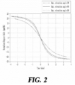
- FIG. 2 is a graph illustrating a normalized shift amount of a Doppler frequency according to one embodiment.
- a low earth orbit (LEO) satellite with an altitude of 600 km may cause a frequency offset of up to 23 ppm, and the frequency offset may cause a Doppler frequency offset of 23 kHz when the LEO satellite uses a carrier frequency in 1 GHz band. Since the satellite at the altitude of 600 km moves at about 28,000 km/h, the magnitude of the Doppler frequency offset may vary according to the position of the satellite. Such a change in the Doppler frequency is illustrated in FIG. 2 .
- a Doppler frequency change rate may be calculated through a normalized Doppler shift. For example, since the Doppler frequency change rate is approximately 200 Hz/s maximum when the satellite at the altitude of 600 km uses a carrier frequency in the 1 GHz band, when the length of a communication packet is increased, a Doppler frequency offset estimated by a preamble at the front side of a frame may be changed at the rear side of the frame due to the Doppler frequency change rate. That is, a difference occurs between frequency offsets of a front side of a packet and a rear side of a packet, and when a frequency of the rear side of the packet is compensated for by using a result estimated in the preamble, a packet error occurs.
- a time length of one packet is about 0.98 seconds, and thus, referring to FIG. 2 , a difference between a frequency offset estimated by a preamble and a frequency offset at the end of the packet may be about 200 Hz.
- a terminal Unlike the ground where a negligible Doppler frequency offset occurs, in a low earth orbit satellite channel, a terminal needs to periodically measure a frequency offset and check a frequency change due to a Doppler frequency change rate.
- An IoT terminal having a good calculation capability may estimate a Doppler frequency change based on the received LoRa preamble to predict a Doppler frequency change rate and use the prediction result for frequency correction.
- FIG. 3 is a diagram illustrating a frame structure of a wireless communication system according to one embodiment.
- the terminal in order to directly transmit a signal to a base station (e.g., LEO satellite) having very high mobility, the terminal predicts a Doppler frequency offset and a Doppler frequency change rate and uses the prediction result in frequency correction, thereby achieving higher reliability than the conventional case.
- two terminals may increase a packet detection probability in a one-to-one communication system in which they directly communicate with each other through a base station having very high mobility based on a packet structure robust to the Doppler effect.
- a transmission apparatus can periodically/aperiodically transmit a pilot symbol in the middle of the payload, and a reception apparatus can reduce packet errors by tracking the pilot symbol inserted in the middle of the payload.
- pilot symbols may be arranged according to a spreading factor.
- one pilot symbol may be one reference chirp modulation symbol or a plurality of reference chirp modulation symbols.
- the plurality of reference chirp modulation symbols may include the same information.
- the reception apparatus may correct the frequency offset of the payload appearing after the pilot symbol based on the pilot symbol inserted in the payload.
- the transmission apparatus may transmit more pilot symbols in the middle of the payload as the spreading factor increases.
- the spreading factor increases by one level, the length of one symbol increases twofold, and thus a larger number of pilot symbols may be transmitted in the middle of the payload that is modulated by the larger spreading factor. For example, if the number of pilot symbols periodically transmitted in the payload section is b when the spreading factor is a, the number of pilot symbols may be 2b when the spreading factor is a+1.
- the frequency bandwidth of one chip is 61 Hz
- the payload is 19 symbols
- the length of one symbol is 16.4 ms
- the length of one frame is 508 ms.
- the Doppler frequency change rate is 200 Hz/s
- a difference of up to two chips may occur because a difference between frequency offsets at both sides of a frame is 100 Hz. Therefore, in order to reduce decoding errors, at least four pilots need to be arranged between 19 symbols of the payload. That is, it is required to arrange one pilot for every four to five symbols to estimate the changed Doppler frequency offset.
- the frequency bandwidth of the chip is 31 Hz
- the payload is 17 symbols
- the length of one symbol is 33 ms (0.033 sec)
- the length of one frame is 957 ms.
- the Doppler frequency change rate is 200 Hz/s
- the frequency error between both sides of the frame becomes 191.4 Hz, and thus a difference of up to 7 chips may occur. Therefore, when one pilot signal is transmitted every two to three symbols, the reception apparatus may receive the packet without an error even when the Doppler frequency change rate is the maximum.
- the Doppler frequency change rate of 200 Hz/s may generate an error of 6.6 Hz per one symbol (0.033 sec), and in this case, when the number of symbols is 2.35, the frequency error exceeds half (15.5 Hz) of the frequency bandwidth 31 Hz of the chip, and thus, when the maximum change of 200 Hz occurs, one pilot symbol needs to be transmitted every two symbols.
- the terminal may estimate an orbit of the satellite, a Doppler frequency offset, and a Doppler frequency change rate by using information received from the satellite. That is, when the terminal having all the information about the satellite transmits an uplink signal to the satellite, the terminal can accurately calculate the Doppler frequency offset and the Doppler frequency change rate, and thus the terminal can compensate for the Doppler frequency offset in advance and transmit the uplink signal without transmitting the pilot signal.
- a terminal may receive a beacon signal transmitted from a satellite, but may know only orbit and altitude information of the satellite.
- the terminal may calculate a Doppler frequency offset and a maximum value of a Doppler frequency change rate at a transmission timing of the terminal, and may arrange a pilot signal between symbols of the payload based on the Doppler frequency offset and the maximum Doppler frequency change rate.
- the terminal may arrange and transmit a pilot signal between symbols of the payload before the accumulated value of the Doppler frequency change rate exceeds a half chip, and the satellite receiving the packet from the terminal may obtain correction information for frequency correction from the pilot signal.
- the terminal may insert information indicating that the pilot signal exists in the payload and information on the period of the pilot signal in the header and the like.
- a terminal cannot perform bidirectional communication with a satellite and may transmit an uplink signal to the satellite. That is, when the terminal does not have the capability of receiving a signal transmitted from the satellite, the terminal needs to know a target packet error rate and the transmittable time. For example, a time for which a low earth orbit satellite at an altitude of 600 km can be connected to a terminal on the ground may be a maximum of 10 minutes.
- the terminal may know in advance a section or a window of time time in which the Doppler frequency change rate is large based on the Doppler frequency shift amount of FIG. 2 in consideration of a movement time and a movement speed of the satellite.
- the terminal can insert a pilot signal between symbols of the payload when a window of time in which the Doppler frequency change rate is the maximum is included in a time period during which the terminal is exposed to the satellite to transmit an uplink signal in consideration of a Doppler frequency shift amount and a target packet error rate, and accordingly, significantly improved performance can be expected in terms of the packet error rate and the packet throughput.
- FIG. 4 is a block diagram illustrating a transmission apparatus according to another embodiment.
- the transmission apparatus may be implemented as a computer system, for example, a computer-readable medium.
- the computer system 200 may include at least one of a processor 210, a memory 230, an input interface device 250, an output interface device 260, and a storage device 240, which communicate with each other via a bus 270.
- the computer system 200 may also include a communication unit 220 linked to a network.
- the processor 210 may be a central processing unit, CPU, or a semiconductor device that executes instructions stored in the memory 230 or the storage device 240.
- the memory 230 and the storage device 240 may include various types of volatile or nonvolatile storage mediums.
- the memory may include a read only memory (ROM) and a random access memory (RAM).
- ROM read only memory
- RAM random access memory
- the memory may be located inside or outside the processor, and the memory may be connected to the processor through various known means.
- the memory is various types of volatile or nonvolatile storage mediums, and for example, the memory may include the read-only memory (ROM) or the random access memory (RAM).
- the embodiment of the present disclosure may be implemented as a method implemented in a computer or may be implemented as a non-transitory computer-readable medium in which computer-executable instructions are stored.
- the computer-readable instructions when executed by the processor, may perform the method according to at least one aspect of the present disclosure.
- the communication unit 220 may transmit or receive a wired signal or a wireless signal.
- the embodiments of the present disclosure are not implemented only through the apparatuses and/or methods described so far, but may also be implemented through a program for implementing a function corresponding to the configuration of the embodiments of the present disclosure or a recording medium having the program recorded thereon, and such an implementation can be easily implemented by those having ordinary skill in the art from the description of the embodiments described above.
- the method e.g., a network management method, a data transmission method, a transmission schedule generation method, etc.
- the embodiments of the present disclosure may be implemented in the form of program instructions that can be executed through various computer means, and may be recorded in a computer-readable medium.
- the computer-readable medium may include a program instruction, a data file, a data structure, and the like, alone or in combination.
- the program instruction recorded in the computer-readable medium may be specially designed and configured for the embodiment of the present disclosure, or may be known to and usable by those having ordinariy skill in the art of computer software.
- the computer-readable recording medium may include a hardware device configured to store and execute the program instruction.
- the computer-readable recording medium may be a magnetic medium such as a hard disk, a floppy disk and a magnetic tape, an optical medium such as a CD-ROM and a DVD, a magneto-optical medium such as a floptical disk, a ROM, a RAM, a flash memory, or the like.
- the program instruction may include not only machine codes such as those made by a compiler, but also high-level language codes that can be executed by a computer through an interpreter.
Landscapes
- Engineering & Computer Science (AREA)
- Signal Processing (AREA)
- Computer Networks & Wireless Communication (AREA)
- Mobile Radio Communication Systems (AREA)
Abstract
Description
- The present disclosure relates to an apparatus and a method for transmitting an uplink signal based on a Doppler frequency change.
- IoT technology in the terrestrial network includes LoRa, Ingenu, NB-IoT, etc. IoT technology for high-speed mobile bodies is being studied based on IoT technology that is being serviced on the terrestrial network. The frame structure of the existing LoRa system is shown in
FIG. 1 . - The symbols of the frames of the LoRa system serviced through the terrestrial network are used for preamble (8 symbols), frame and frequency synchronizations (4.25 (2+2.25) symbols), header and cyclic redundancy check (CRC) for the header (4 bytes (4/8 Hamming code is used)), payload (NPL bytes), and CRC for the payload. A chirp spread spectrum modulation scheme is used for modulation of the preamble, synchronization, and payload symbol, and an extended Hamming code is used as an error correction code.
- The symbol modulation scheme of the LoRa is the chirp spread spectrum modulation scheme, and when a spreading factor, SF, is applied to the modulation scheme, one symbol includes 2SF number of continuous chips. The baseband frequency of the symbol continuously increases over time.
- When the LoRa system is used for IoT communication of high-speed mobile bodies, that is, when the high-speed mobile body transmits a signal to an IoT terminal or the IoT terminal transmits a signal to the high-speed mobile body, reception performance may be significantly reduced due to a Doppler effect generated due to a large relative speed between the high-speed mobile body and the IoT terminal.
- One embodiment of the present disclosure provides an apparatus for transmitting a signal based on a Doppler frequency change.
- Another embodiment of the present disclosure provides a method of transmitting a signal based on a Doppler frequency change.
- According to an embodiment, an apparatus for transmitting an uplink signal to a base station is provided. The apparatus includes a processor, a memory, and a communication unit, where the processor executes a program stored in the memory to perform the steps of: calculating a maximum change rate of a Doppler frequency; arranging a pilot signal in the uplink signal based on a spreading factor of the uplink signal and the maximum change rate of the Doppler frequency; and transmitting the uplink signal in which the pilot signal is arranged to the base station.
- In the apparatus, when performing the step of arranging the pilot signal in the uplink signal based on the spreading factor of the uplink signal and the maximum change rate of the Doppler frequency, the processor may perform a step of arranging the pilot signal between symbols of a payload of the uplink signal.
- In the apparatus, when performing the step of arranging the pilot signal between the symbols of the payload of the uplink signal, the processor may perform a step of periodically arranging the pilot signal between the symbols of the payload.
- In the apparatus, when performing the step of periodically arranging the pilot signal between the symbols of the payload, the processor may perform a step of inserting information indicating that the pilot signal is present in the payload and information on a period of the pilot signal into a header of the uplink signal.
- In the apparatus, when performing the step of arranging the pilot signal in the uplink signal based on the spreading factor of the uplink signal and the maximum change rate of the Doppler frequency, the processor may perform the steps of: determining a frequency bandwidth of a chip based on a bandwidth of the uplink signal and the spreading factor; and determining the number of the pilot signals based on the maximum change rate of the Doppler frequency and the frequency bandwidth of the chip.
- In the apparatus, when performing the step of arranging the pilot signal in the uplink signal based on the spreading factor of the uplink signal and the maximum change rate of the Doppler frequency, the processor may perform the steps of: determining a frequency bandwidth of a chip based on a bandwidth of the uplink signal and the spreading factor; and determining a period of the pilot signal based on the maximum change rate of the Doppler frequency and the frequency bandwidth of the chip.
- In the apparatus, prior to the step of calculating the maximum change rate of the Doppler frequency, the processor may further perform a step of determining a window of time in which the change rate of the Doppler frequency is maximum in consideration of a movement time and a movement speed of the base station.
- In the apparatus, the processor executes the program to perform the step of calculating the maximum change rate of the Doppler frequency when the window of time time in which the change rate of the Doppler frequency is maximum is included in a time period during which a terminal is exposed to the base station to transmit the uplink signal.
- According to another embodiment, method of transmitting an uplink signal to a base station is provided. The method includes calculating a maximum change rate of a Doppler frequency, arranging a pilot signal in the uplink signal based on a spreading factor of the uplink signal and the maximum change rate of the Doppler frequency, and transmitting the uplink signal in which the pilot signal is arranged to the base station.
- In the method, the arranging of the pilot signal in the uplink signal based on the spreading factor of the uplink signal and the maximum change rate of the Doppler frequency may include arranging the pilot signal between symbols of a payload of the uplink signal.
- In the method, the arranging of the pilot signal between the symbols of the payload of the uplink signal may include periodically arranging the pilot signal between the symbols of the payload.
- In the method, the periodically arranging of the pilot signal between the symbols of the payload may include inserting information indicating that the pilot signal is present in the payload and information on a period of the pilot signal into a header of the uplink signal.
- In the method, the arranging of the pilot signal in the uplink signal based on the spreading factor of the uplink signal and the maximum change rate of the Doppler frequency may include determining a frequency bandwidth of a chip based on a bandwidth of the uplink signal and the spreading factor, and determining the number of the pilot signals based on the maximum change rate of the Doppler frequency and the frequency bandwidth of the chip.
- In the method, the arranging of the pilot signal in the uplink signal based on the spreading factor of the uplink signal and the maximum change rate of the Doppler frequency may include determining a frequency bandwidth of a chip based on a bandwidth of the uplink signal and the spreading factor, and determining a period of the pilot signal based on the maximum change rate of the Doppler frequency and the frequency bandwidth of the chip.
- The method may further include determining a window of time in which a change rate of the Doppler frequency is maximum in consideration of a movement time and a movement speed of the base station prior to calculating the maximum change rate of the Doppler frequency.
- In the method, the maximum change rate of the Doppler frequency may be calculated when the window of time in which the change rate of the Doppler frequency is maximum is included in a time period during which a terminal is exposed to the base station to transmit the uplink signal.
- According to another embodiment, an apparatus for receiving an uplink signal is provided. The apparatus includes a processor, a memory, and a communication unit, where the processor executes a program stored in the memory to perform the steps of: receiving the uplink signal, receiving at least one pilot signal arranged between payloads in the uplink signal, and obtaining correction information for frequency correction from the at least one pilot signal.
- In a situation in which change in a carrier signal frequency due to the Doppler frequency and Doppler frequency change, in the waveform for conventional IoT, through transmission of a pilot signal it is possible to increase the reliability of an IoT environment having high-speed mobility, such as a satellite. That is, the reliability may be secured by increasing probability of packet detection in satellite IoT and reducing packet error probability.
-
-
FIG. 1 is a diagram illustrating a frame structure of a LoRa communication system. -
FIG. 2 is a graph illustrating a normalized amount of shift of a Doppler frequency according to one embodiment of the present disclosure. -
FIG. 3 is a diagram illustrating a frame structure of a wireless communication system according to one embodiment of the present disclosure. -
FIG. 4 is a block diagram illustrating a transmission apparatus according to one embodiment of the present disclosure. - Hereinafter, the embodiments of the present disclosure are described in detail for those having ordinary skill in the art to easily practice, with reference to the accompanying drawings. The present disclosure, however, may be embodied in various forms, and should not be construed as being limited only to the illustrated embodiments. In the drawings, elements irrelevant to the present disclosure are omitted for the simplicity of explanation, and like reference numerals denote like elements throughout the entire specification.
- Throughout the present specification, the terminal may refer to a user equipment (UE), a mobile station (MS), a mobile terminal (MT), an advanced mobile station (AMS), a high reliability mobile station (HR-MS), a subscriber station (SS), a portable subscriber station (PSS), an access terminal (AT), a machine type communication device (MTC device), etc. and may also include all or some of the functionalities of UE, MS, MT, AMS, HR-MS, SS, PSS, AT, or the like.
- In addition, a base station (BS) may refer to a node B, an evolved node B (eNB), a gNB, an advanced base station (ABS), a high reliability base station (HR-BS), an access point (AP), a radio access station (RAS), a base transceiver station (BTS), a mobile multihop relay (MMR)-BS, a relay station (RS) that performs a role of a base station, a relay node (RN) that performs a role of a base station, an advanced relay station (ARS) that performs a role of a base station, a high reliability relay station (HR-RS) that performs a role of a base station, a small base station (a femto BS, a home node B (HNB), a home eNodeB (HeNB), a pico BS, a macro BS, a micro BS, etc.), and the like, and may also include all or some of the functionalities of NB, eNB, gNB, ABS, AP, RAS, BTS, MMR-BS, RS, RN, ARS, HR-RS, small base station, and the like.
- Throughout the present specification, when a part "includes or comprises" a component, this means that the part may further include other components, rather than excluding other components, unless specifically stated otherwise.
- In the present specification, a singular expression may be interpreted as single or plural unless an explicit expression such as "one" or "single" is used.
- As used herein, "and/or" indicates each of the stated components and all combinations of one or more of the stated components.
- In the present specification, terms including ordinal numbers such as first, second, etc. may be used to describe various components, but the components are not limited by the terms. The terms are used only for the purpose of distinguishing one component from another component. For example, a first element may be termed a second element and vice versa, without departing from the scope of the present disclosure.
- In the flowchart described with reference to the drawings in the present specification, the order of operations may be changed, several operations may be merged, a certain operation may be divided, and a specific operation may not be performed.
-
FIG. 2 is a graph illustrating a normalized shift amount of a Doppler frequency according to one embodiment. - A low earth orbit (LEO) satellite with an altitude of 600 km may cause a frequency offset of up to 23 ppm, and the frequency offset may cause a Doppler frequency offset of 23 kHz when the LEO satellite uses a carrier frequency in 1 GHz band. Since the satellite at the altitude of 600 km moves at about 28,000 km/h, the magnitude of the Doppler frequency offset may vary according to the position of the satellite. Such a change in the Doppler frequency is illustrated in
FIG. 2 . - Referring to
FIG. 2 , a Doppler frequency change rate may be calculated through a normalized Doppler shift. For example, since the Doppler frequency change rate is approximately 200 Hz/s maximum when the satellite at the altitude of 600 km uses a carrier frequency in the 1 GHz band, when the length of a communication packet is increased, a Doppler frequency offset estimated by a preamble at the front side of a frame may be changed at the rear side of the frame due to the Doppler frequency change rate. That is, a difference occurs between frequency offsets of a front side of a packet and a rear side of a packet, and when a frequency of the rear side of the packet is compensated for by using a result estimated in the preamble, a packet error occurs. - For example, performance degradation due to Doppler frequency offset and Doppler frequency change rate may be more serious in the LoRa packet. In order for a packet modulated in the LoRa system to achieve a positive link budget in a satellite channel, a high spreading factor needs to be used because the high spreading factor greatly increases a length of the packet.
- For example, when a LoRa packet having a bandwidth of 125 kHz and a payload of 100 bits is encoded with a 1/2 Hamming code and is modulated with SF12, a time length of one packet is about 0.98 seconds, and thus, referring to
FIG. 2 , a difference between a frequency offset estimated by a preamble and a frequency offset at the end of the packet may be about 200 Hz. - In the case of a LoRa packet having a bandwidth of 125 kHz, since the frequency bandwidth of one chip is 125,000/212 (≈ 30.5) Hz, a difference of up to 7 chips may occur when the frequency offset difference between both sides of one packet is 200 Hz. Since an error occurs when a difference of half a chip or more occurs when demodulating and decoding a symbol, it is necessary to reduce the frequency difference of 7 chips to a difference of half a chip or less.
- Unlike the ground where a negligible Doppler frequency offset occurs, in a low earth orbit satellite channel, a terminal needs to periodically measure a frequency offset and check a frequency change due to a Doppler frequency change rate. An IoT terminal having a good calculation capability may estimate a Doppler frequency change based on the received LoRa preamble to predict a Doppler frequency change rate and use the prediction result for frequency correction.
-
FIG. 3 is a diagram illustrating a frame structure of a wireless communication system according to one embodiment. - In the present disclosure, in order to directly transmit a signal to a base station (e.g., LEO satellite) having very high mobility, the terminal predicts a Doppler frequency offset and a Doppler frequency change rate and uses the prediction result in frequency correction, thereby achieving higher reliability than the conventional case. For example, two terminals may increase a packet detection probability in a one-to-one communication system in which they directly communicate with each other through a base station having very high mobility based on a packet structure robust to the Doppler effect.
- In the packet of the conventional IoT system, since the packet is detected through the preamble and the frequency is corrected through the synchronization symbol, when the Doppler frequency change occurs in the payload, the frequency error cannot be corrected and an error floor may occur.
- A transmission apparatus according to one embodiment can periodically/aperiodically transmit a pilot symbol in the middle of the payload, and a reception apparatus can reduce packet errors by tracking the pilot symbol inserted in the middle of the payload.
- Referring to
FIG. 3 , in a frame structure according to one embodiment, pilot symbols may be arranged according to a spreading factor. Here, one pilot symbol may be one reference chirp modulation symbol or a plurality of reference chirp modulation symbols. When one pilot symbol includes a plurality of reference chirp modulation symbols, the plurality of reference chirp modulation symbols may include the same information. The reception apparatus may correct the frequency offset of the payload appearing after the pilot symbol based on the pilot symbol inserted in the payload. - The transmission apparatus according to one embodiment may transmit more pilot symbols in the middle of the payload as the spreading factor increases. When the spreading factor increases by one level, the length of one symbol increases twofold, and thus a larger number of pilot symbols may be transmitted in the middle of the payload that is modulated by the larger spreading factor. For example, if the number of pilot symbols periodically transmitted in the payload section is b when the spreading factor is a, the number of pilot symbols may be 2b when the spreading factor is a+1.
- For example, when a signal is transmitted at a carrier frequency of 1 GHz in a bandwidth of 125 kHz, if a spreading factor of 11 is used, the frequency bandwidth of one chip is 61 Hz, the payload is 19 symbols, the length of one symbol is 16.4 ms, and the length of one frame is 508 ms. In this case, when the Doppler frequency change rate is 200 Hz/s, a difference of up to two chips may occur because a difference between frequency offsets at both sides of a frame is 100 Hz. Therefore, in order to reduce decoding errors, at least four pilots need to be arranged between 19 symbols of the payload. That is, it is required to arrange one pilot for every four to five symbols to estimate the changed Doppler frequency offset.
- As another example, when the spreading factor of 12 is used, the frequency bandwidth of the chip is 31 Hz, the payload is 17 symbols, the length of one symbol is 33 ms (0.033 sec), and the length of one frame is 957 ms. When the Doppler frequency change rate is 200 Hz/s, the frequency error between both sides of the frame becomes 191.4 Hz, and thus a difference of up to 7 chips may occur. Therefore, when one pilot signal is transmitted every two to three symbols, the reception apparatus may receive the packet without an error even when the Doppler frequency change rate is the maximum.
- That is, the Doppler frequency change rate of 200 Hz/s may generate an error of 6.6 Hz per one symbol (0.033 sec), and in this case, when the number of symbols is 2.35, the frequency error exceeds half (15.5 Hz) of the frequency bandwidth 31 Hz of the chip, and thus, when the maximum change of 200 Hz occurs, one pilot symbol needs to be transmitted every two symbols.
- When a terminal according to one embodiment is capable of receiving a beacon signal of a satellite, the terminal may estimate an orbit of the satellite, a Doppler frequency offset, and a Doppler frequency change rate by using information received from the satellite. That is, when the terminal having all the information about the satellite transmits an uplink signal to the satellite, the terminal can accurately calculate the Doppler frequency offset and the Doppler frequency change rate, and thus the terminal can compensate for the Doppler frequency offset in advance and transmit the uplink signal without transmitting the pilot signal.
- A terminal according to another embodiment may receive a beacon signal transmitted from a satellite, but may know only orbit and altitude information of the satellite. When the terminal knows the orbit and altitude information of the satellite, the terminal may calculate a Doppler frequency offset and a maximum value of a Doppler frequency change rate at a transmission timing of the terminal, and may arrange a pilot signal between symbols of the payload based on the Doppler frequency offset and the maximum Doppler frequency change rate. For example, the terminal may arrange and transmit a pilot signal between symbols of the payload before the accumulated value of the Doppler frequency change rate exceeds a half chip, and the satellite receiving the packet from the terminal may obtain correction information for frequency correction from the pilot signal. In this case, the terminal may insert information indicating that the pilot signal exists in the payload and information on the period of the pilot signal in the header and the like.
- A terminal according to still another embodiment cannot perform bidirectional communication with a satellite and may transmit an uplink signal to the satellite. That is, when the terminal does not have the capability of receiving a signal transmitted from the satellite, the terminal needs to know a target packet error rate and the transmittable time. For example, a time for which a low earth orbit satellite at an altitude of 600 km can be connected to a terminal on the ground may be a maximum of 10 minutes. In order for the terminal to transmit an uplink signal during the time when the terminal is exposed to the satellite, the terminal may know in advance a section or a window of time time in which the Doppler frequency change rate is large based on the Doppler frequency shift amount of
FIG. 2 in consideration of a movement time and a movement speed of the satellite. That is, insertion of the pilot signal into all packets assuming maximum Doppler frequency change rate even when connection between the terminal and the satellite is limited may be disadvantageous in terms of packet throughput. Accordingly, the terminal can insert a pilot signal between symbols of the payload when a window of time in which the Doppler frequency change rate is the maximum is included in a time period during which the terminal is exposed to the satellite to transmit an uplink signal in consideration of a Doppler frequency shift amount and a target packet error rate, and accordingly, significantly improved performance can be expected in terms of the packet error rate and the packet throughput. -
FIG. 4 is a block diagram illustrating a transmission apparatus according to another embodiment. - The transmission apparatus according to another embodiment may be implemented as a computer system, for example, a computer-readable medium. Referring to
FIG. 4 , thecomputer system 200 may include at least one of aprocessor 210, amemory 230, aninput interface device 250, anoutput interface device 260, and astorage device 240, which communicate with each other via abus 270. Thecomputer system 200 may also include acommunication unit 220 linked to a network. Theprocessor 210 may be a central processing unit, CPU, or a semiconductor device that executes instructions stored in thememory 230 or thestorage device 240. Thememory 230 and thestorage device 240 may include various types of volatile or nonvolatile storage mediums. For example, the memory may include a read only memory (ROM) and a random access memory (RAM). In the embodiment of the present disclosure, the memory may be located inside or outside the processor, and the memory may be connected to the processor through various known means. The memory is various types of volatile or nonvolatile storage mediums, and for example, the memory may include the read-only memory (ROM) or the random access memory (RAM). - Accordingly, the embodiment of the present disclosure may be implemented as a method implemented in a computer or may be implemented as a non-transitory computer-readable medium in which computer-executable instructions are stored. In one embodiment, when executed by the processor, the computer-readable instructions may perform the method according to at least one aspect of the present disclosure.
- The
communication unit 220 may transmit or receive a wired signal or a wireless signal. - Meanwhile, the embodiments of the present disclosure are not implemented only through the apparatuses and/or methods described so far, but may also be implemented through a program for implementing a function corresponding to the configuration of the embodiments of the present disclosure or a recording medium having the program recorded thereon, and such an implementation can be easily implemented by those having ordinary skill in the art from the description of the embodiments described above. Specifically, the method (e.g., a network management method, a data transmission method, a transmission schedule generation method, etc.) according to the embodiments of the present disclosure may be implemented in the form of program instructions that can be executed through various computer means, and may be recorded in a computer-readable medium. The computer-readable medium may include a program instruction, a data file, a data structure, and the like, alone or in combination. The program instruction recorded in the computer-readable medium may be specially designed and configured for the embodiment of the present disclosure, or may be known to and usable by those having ordinariy skill in the art of computer software. The computer-readable recording medium may include a hardware device configured to store and execute the program instruction. For example, the computer-readable recording medium may be a magnetic medium such as a hard disk, a floppy disk and a magnetic tape, an optical medium such as a CD-ROM and a DVD, a magneto-optical medium such as a floptical disk, a ROM, a RAM, a flash memory, or the like. The program instruction may include not only machine codes such as those made by a compiler, but also high-level language codes that can be executed by a computer through an interpreter.
- Although the embodiments of the present disclosure have been described above in detail, the scope of the present disclosure is not limited thereto, and various modifications and improvements made by those skilled in the art using the basic concept of the present disclosure defined in the following claims also belong to the scope of the present disclosure.
Claims (15)
- An apparatus for transmitting an uplink signal to a base station, the apparatus comprising:a processor 210; a memory 230; and a communication unit 220,wherein the processor 210 executes a program stored in the memory 230 to perform the steps of:calculating a maximum change rate of a Doppler frequency;arranging a pilot signal in the uplink signal based on a spreading factor of the uplink signal and the maximum change rate of the Doppler frequency; andtransmitting the uplink signal in which the pilot signal is arranged to the base station.
- The apparatus of claim 1, wherein, when performing the step of arranging the pilot signal in the uplink signal based on the spreading factor of the uplink signal and the maximum change rate of the Doppler frequency, the processor 210 performs a step of arranging the pilot signal between symbols of a payload of the uplink signal.
- The apparatus of claim 2, wherein, when performing the step of arranging the pilot signal between the symbols of the payload of the uplink signal, the processor 210 performs a step of periodically arranging the pilot signal between the symbols of the payload.
- The apparatus of claim 3, wherein, when performing the step of periodically arranging the pilot signal between the symbols of the payload, the processor 210 performs a step of inserting information indicating that the pilot signal is present in the payload and information on a period of the pilot signal into a header of the uplink signal.
- The apparatus of one of claims 1 to 4, wherein, when performing the step of arranging the pilot signal in the uplink signal based on the spreading factor of the uplink signal and the maximum change rate of the Doppler frequency, the processor 210 performs the steps of: determining a frequency bandwidth of a chip based on a bandwidth of the uplink signal and the spreading factor; and determining the number of the pilot signals based on the maximum change rate of the Doppler frequency and the frequency bandwidth of the chip.
- The apparatus of one of claims 1 to 5, wherein, when performing the step of arranging the pilot signal in the uplink signal based on the spreading factor of the uplink signal and the maximum change rate of the Doppler frequency, the processor 210 performs the steps of: determining a frequency bandwidth of a chip based on a bandwidth of the uplink signal and the spreading factor; and determining a period of the pilot signal based on the maximum change rate of the Doppler frequency and the frequency bandwidth of the chip.
- The apparatus of one of claims 1 to 6, wherein, prior to the step of calculating the maximum change rate of the Doppler frequency, the processor 210 further performs a step of determining a window of time in which the change rate of the Doppler frequency is maximum in consideration of a movement time and a movement speed of the base station.
- The apparatus of claim 7, wherein the processor 210 executes the program to perform the step of calculating the maximum change rate of the Doppler frequency when the window of time time in which the change rate of the Doppler frequency is maximum is included in a time period during which a terminal is exposed to the base station to transmit the uplink signal.
- A method of transmitting an uplink signal to a base station, the method comprising:calculating a maximum change rate of a Doppler frequency;arranging a pilot signal in the uplink signal based on a spreading factor of the uplink signal and the maximum change rate of the Doppler frequency; andtransmitting the uplink signal in which the pilot signal is arranged to the base station.
- The method of claim 9, wherein the arranging of the pilot signal in the uplink signal based on the spreading factor of the uplink signal and the maximum change rate of the Doppler frequency includes arranging the pilot signal between symbols of a payload of the uplink signal.
- The method of claim 10, wherein the arranging of the pilot signal between the symbols of the payload of the uplink signal includes periodically arranging the pilot signal between the symbols of the payload.
- The method of claim 11, wherein the periodically arranging of the pilot signal between the symbols of the payload includes inserting information indicating that the pilot signal is present in the payload and information on a period of the pilot signal into a header of the uplink signal.
- The method of one of claims 9 to 12, wherein the arranging of the pilot signal in the uplink signal based on the spreading factor of the uplink signal and the maximum change rate of the Doppler frequency includes:determining a frequency bandwidth of a chip based on a bandwidth of the uplink signal and the spreading factor; anddetermining the number of the pilot signals based on the maximum change rate of the Doppler frequency and the frequency bandwidth of the chip.
- The method of one of claims 9 to 13, wherein the arranging of the pilot signal in the uplink signal based on the spreading factor of the uplink signal and the maximum change rate of the Doppler frequency includes:determining a frequency bandwidth of a chip based on a bandwidth of the uplink signal and the spreading factor; anddetermining a period of the pilot signal based on the maximum change rate of the Doppler frequency and the frequency bandwidth of the chip.
- An apparatus for receiving an uplink signal, the apparatus comprising:a processor 210; a memory 230; and a communication unit 220,wherein the processor 210 executes a program stored in the memory 230 to perform the steps of:receiving the uplink signal;receiving at least one pilot signal arranged between payloads in the uplink signal; andobtaining correction information for frequency correction from the at least one pilot signal.
Applications Claiming Priority (1)
| Application Number | Priority Date | Filing Date | Title |
|---|---|---|---|
| KR1020220124467A KR102957176B1 (en) | 2022-09-29 | 2022-09-29 | Method and apparatus for transmitting a uplink signal based on doppler frequency variation |
Publications (2)
| Publication Number | Publication Date |
|---|---|
| EP4346108A1 true EP4346108A1 (en) | 2024-04-03 |
| EP4346108B1 EP4346108B1 (en) | 2026-04-15 |
Family
ID=86052334
Family Applications (1)
| Application Number | Title | Priority Date | Filing Date |
|---|---|---|---|
| EP23168149.5A Active EP4346108B1 (en) | 2022-09-29 | 2023-04-16 | Method and apparatus for transmitting an uplink signal based on doppler frequency variation |
Country Status (2)
| Country | Link |
|---|---|
| EP (1) | EP4346108B1 (en) |
| KR (1) | KR102957176B1 (en) |
Cited By (2)
| Publication number | Priority date | Publication date | Assignee | Title |
|---|---|---|---|---|
| US20230308129A1 (en) * | 2022-03-24 | 2023-09-28 | Saya Life, Inc. | Adaptive spreading factor matching for single channel lora receivers |
| RU2843606C1 (en) * | 2024-04-24 | 2025-07-17 | Акционерное общество "ОКБ Пятое поколение" | Satellite terminal and method for communication of satellite terminal and satellite |
Citations (2)
| Publication number | Priority date | Publication date | Assignee | Title |
|---|---|---|---|---|
| EP1881625A2 (en) * | 2006-07-19 | 2008-01-23 | Broadcom Corporation | Method and system for satellite communication |
| US20100098245A1 (en) * | 2007-03-27 | 2010-04-22 | Hughes Network Systems | Method and system for providing spread scrambled coded multiple access (sscma) |
-
2022
- 2022-09-29 KR KR1020220124467A patent/KR102957176B1/en active Active
-
2023
- 2023-04-16 EP EP23168149.5A patent/EP4346108B1/en active Active
Patent Citations (2)
| Publication number | Priority date | Publication date | Assignee | Title |
|---|---|---|---|---|
| EP1881625A2 (en) * | 2006-07-19 | 2008-01-23 | Broadcom Corporation | Method and system for satellite communication |
| US20100098245A1 (en) * | 2007-03-27 | 2010-04-22 | Hughes Network Systems | Method and system for providing spread scrambled coded multiple access (sscma) |
Non-Patent Citations (2)
| Title |
|---|
| GIUGNO L ET AL: "Optimal Pilot Symbol Distribution for Efficient and Low-Complexity Doppler-Shift and Doppler-Rate Estimation in Bursty Transmission", PROCEEDINGS OF THE 2007 IEEE INTERNATIONAL CONFERENCE ON COMMUNICATIONS (ICC 2007), 24-28 JUNE 2007, GLASGOW, UK, IEEE, PISCATAWAY, NJ, USA, 1 June 2007 (2007-06-01), pages 5993 - 5998, XP031126626, ISBN: 978-1-4244-0353-0 * |
| PENG HAN ET AL: "Adaptive pilot design based on Doppler frequency shift estimation for OFDM system", COMPUTER DESIGN AND APPLICATIONS (ICCDA), 2010 INTERNATIONAL CONFERENCE ON, vol. 3, 1 January 2010 (2010-01-01), pages V4 - 533, XP055154305, ISBN: 978-1-42-447164-5, DOI: 10.1109/ICCDA.2010.5540707 * |
Cited By (3)
| Publication number | Priority date | Publication date | Assignee | Title |
|---|---|---|---|---|
| US20230308129A1 (en) * | 2022-03-24 | 2023-09-28 | Saya Life, Inc. | Adaptive spreading factor matching for single channel lora receivers |
| US12184325B2 (en) * | 2022-03-24 | 2024-12-31 | Saya Life, Inc. | Adaptive spreading factor matching for single channel LoRa receivers |
| RU2843606C1 (en) * | 2024-04-24 | 2025-07-17 | Акционерное общество "ОКБ Пятое поколение" | Satellite terminal and method for communication of satellite terminal and satellite |
Also Published As
| Publication number | Publication date |
|---|---|
| EP4346108B1 (en) | 2026-04-15 |
| KR102957176B1 (en) | 2026-04-24 |
| KR20240044904A (en) | 2024-04-05 |
Similar Documents
| Publication | Publication Date | Title |
|---|---|---|
| US11184100B2 (en) | Narrow band internet of things communications over a satellite communication system | |
| US12213093B2 (en) | System and method for using a time gap | |
| US20230098798A1 (en) | User equipment and method for maintaining uplink (ul) synchronization in a non-terrestrial network (ntn) | |
| KR20210109624A (en) | Determining Timing Advance in Wireless Networks | |
| US20110116386A1 (en) | Transmission control in a wireless communication system | |
| KR102837933B1 (en) | Downlink-uplink timing relationship system and method | |
| US12294871B2 (en) | Method and apparatus for signal transmission and reception in communication system | |
| US20250240825A1 (en) | Ue-specific random access preamble reception error indication and assistance information for wireless networks | |
| US20230283437A1 (en) | Method, device and computer readable medium for communication | |
| US20210076339A1 (en) | Downlink timing advanced for common synchronization signal acquisition | |
| US20250324422A1 (en) | Transmission / reception of an uplink signal via a wireless access interface | |
| US20220131599A1 (en) | Method and apparatus for timing management in communication system | |
| EP4346108B1 (en) | Method and apparatus for transmitting an uplink signal based on doppler frequency variation | |
| US20230422240A1 (en) | Wireless communication method, terminal device, and network device | |
| US20210084602A1 (en) | Reduced system acquisition time for mtc using common synchronization channel | |
| US10951357B1 (en) | System and method for detecting a satellite | |
| US20250175920A1 (en) | Method and apparatus for determining a reception timing of signal in non-terrestrial network | |
| US11671933B2 (en) | Random-access endpoint communication handling for satellite-transported communication links | |
| US20250106797A1 (en) | Method and apparatus for transmitting uplink signal in non-terrestrial network | |
| WO2023050027A1 (en) | Segmented pre-compensation management techniques | |
| US20250039802A1 (en) | Method and apparatus for multi-connectivity in communication system | |
| US12316460B2 (en) | HARQ retransmissions for HARQ feedback | |
| KR20230047928A (en) | Method and apparatus for timing synchronization in communication system | |
| US12294441B2 (en) | Terminal and base station | |
| US20260082344A1 (en) | Communicating a synchronization preamble and response |
Legal Events
| Date | Code | Title | Description |
|---|---|---|---|
| PUAI | Public reference made under article 153(3) epc to a published international application that has entered the european phase |
Free format text: ORIGINAL CODE: 0009012 |
|
| STAA | Information on the status of an ep patent application or granted ep patent |
Free format text: STATUS: THE APPLICATION HAS BEEN PUBLISHED |
|
| AK | Designated contracting states |
Kind code of ref document: A1 Designated state(s): AL AT BE BG CH CY CZ DE DK EE ES FI FR GB GR HR HU IE IS IT LI LT LU LV MC ME MK MT NL NO PL PT RO RS SE SI SK SM TR |
|
| STAA | Information on the status of an ep patent application or granted ep patent |
Free format text: STATUS: REQUEST FOR EXAMINATION WAS MADE |
|
| 17P | Request for examination filed |
Effective date: 20241004 |
|
| RBV | Designated contracting states (corrected) |
Designated state(s): AL AT BE BG CH CY CZ DE DK EE ES FI FR GB GR HR HU IE IS IT LI LT LU LV MC ME MK MT NL NO PL PT RO RS SE SI SK SM TR |
|
| GRAP | Despatch of communication of intention to grant a patent |
Free format text: ORIGINAL CODE: EPIDOSNIGR1 |
|
| STAA | Information on the status of an ep patent application or granted ep patent |
Free format text: STATUS: GRANT OF PATENT IS INTENDED |
|
| RIC1 | Information provided on ipc code assigned before grant |
Ipc: H04B 1/69 20110101AFI20251030BHEP Ipc: H04L 5/00 20060101ALI20251030BHEP |
|
| INTG | Intention to grant announced |
Effective date: 20251118 |
|
| GRAS | Grant fee paid |
Free format text: ORIGINAL CODE: EPIDOSNIGR3 |
|
| GRAA | (expected) grant |
Free format text: ORIGINAL CODE: 0009210 |
|
| STAA | Information on the status of an ep patent application or granted ep patent |
Free format text: STATUS: THE PATENT HAS BEEN GRANTED |
|
| AK | Designated contracting states |
Kind code of ref document: B1 Designated state(s): AL AT BE BG CH CY CZ DE DK EE ES FI FR GB GR HR HU IE IS IT LI LT LU LV MC ME MK MT NL NO PL PT RO RS SE SI SK SM TR |
|
| REG | Reference to a national code |
Ref country code: CH Ref legal event code: F10 Free format text: ST27 STATUS EVENT CODE: U-0-0-F10-F00 (AS PROVIDED BY THE NATIONAL OFFICE) Effective date: 20260415 |
|
| REG | Reference to a national code |
Ref country code: DE Ref legal event code: R096 Ref document number: 602023015152 Country of ref document: DE |