EP4345985A2 - Battery module - Google Patents
Battery module Download PDFInfo
- Publication number
- EP4345985A2 EP4345985A2 EP23163369.4A EP23163369A EP4345985A2 EP 4345985 A2 EP4345985 A2 EP 4345985A2 EP 23163369 A EP23163369 A EP 23163369A EP 4345985 A2 EP4345985 A2 EP 4345985A2
- Authority
- EP
- European Patent Office
- Prior art keywords
- sub
- flow path
- module
- disposed
- battery module
- Prior art date
- Legal status (The legal status is an assumption and is not a legal conclusion. Google has not performed a legal analysis and makes no representation as to the accuracy of the status listed.)
- Granted
Links
Images

Classifications
-
- H—ELECTRICITY
- H01—ELECTRIC ELEMENTS
- H01M—PROCESSES OR MEANS, e.g. BATTERIES, FOR THE DIRECT CONVERSION OF CHEMICAL ENERGY INTO ELECTRICAL ENERGY
- H01M10/00—Secondary cells; Manufacture thereof
- H01M10/60—Heating or cooling; Temperature control
- H01M10/61—Types of temperature control
- H01M10/613—Cooling or keeping cold
-
- H—ELECTRICITY
- H01—ELECTRIC ELEMENTS
- H01M—PROCESSES OR MEANS, e.g. BATTERIES, FOR THE DIRECT CONVERSION OF CHEMICAL ENERGY INTO ELECTRICAL ENERGY
- H01M10/00—Secondary cells; Manufacture thereof
- H01M10/60—Heating or cooling; Temperature control
- H01M10/65—Means for temperature control structurally associated with the cells
- H01M10/655—Solid structures for heat exchange or heat conduction
- H01M10/6554—Rods or plates
-
- H—ELECTRICITY
- H01—ELECTRIC ELEMENTS
- H01M—PROCESSES OR MEANS, e.g. BATTERIES, FOR THE DIRECT CONVERSION OF CHEMICAL ENERGY INTO ELECTRICAL ENERGY
- H01M10/00—Secondary cells; Manufacture thereof
- H01M10/60—Heating or cooling; Temperature control
- H01M10/62—Heating or cooling; Temperature control specially adapted for specific applications
- H01M10/625—Vehicles
-
- H—ELECTRICITY
- H01—ELECTRIC ELEMENTS
- H01M—PROCESSES OR MEANS, e.g. BATTERIES, FOR THE DIRECT CONVERSION OF CHEMICAL ENERGY INTO ELECTRICAL ENERGY
- H01M10/00—Secondary cells; Manufacture thereof
- H01M10/60—Heating or cooling; Temperature control
- H01M10/64—Heating or cooling; Temperature control characterised by the shape of the cells
- H01M10/647—Prismatic or flat cells, e.g. pouch cells
-
- H—ELECTRICITY
- H01—ELECTRIC ELEMENTS
- H01M—PROCESSES OR MEANS, e.g. BATTERIES, FOR THE DIRECT CONVERSION OF CHEMICAL ENERGY INTO ELECTRICAL ENERGY
- H01M10/00—Secondary cells; Manufacture thereof
- H01M10/60—Heating or cooling; Temperature control
- H01M10/65—Means for temperature control structurally associated with the cells
- H01M10/655—Solid structures for heat exchange or heat conduction
- H01M10/6556—Solid parts with flow channel passages or pipes for heat exchange
-
- H—ELECTRICITY
- H01—ELECTRIC ELEMENTS
- H01M—PROCESSES OR MEANS, e.g. BATTERIES, FOR THE DIRECT CONVERSION OF CHEMICAL ENERGY INTO ELECTRICAL ENERGY
- H01M10/00—Secondary cells; Manufacture thereof
- H01M10/60—Heating or cooling; Temperature control
- H01M10/65—Means for temperature control structurally associated with the cells
- H01M10/656—Means for temperature control structurally associated with the cells characterised by the type of heat-exchange fluid
- H01M10/6561—Gases
- H01M10/6566—Means within the gas flow to guide the flow around one or more cells, e.g. manifolds, baffles or other barriers
-
- H—ELECTRICITY
- H01—ELECTRIC ELEMENTS
- H01M—PROCESSES OR MEANS, e.g. BATTERIES, FOR THE DIRECT CONVERSION OF CHEMICAL ENERGY INTO ELECTRICAL ENERGY
- H01M10/00—Secondary cells; Manufacture thereof
- H01M10/60—Heating or cooling; Temperature control
- H01M10/65—Means for temperature control structurally associated with the cells
- H01M10/656—Means for temperature control structurally associated with the cells characterised by the type of heat-exchange fluid
- H01M10/6567—Liquids
-
- H—ELECTRICITY
- H01—ELECTRIC ELEMENTS
- H01M—PROCESSES OR MEANS, e.g. BATTERIES, FOR THE DIRECT CONVERSION OF CHEMICAL ENERGY INTO ELECTRICAL ENERGY
- H01M10/00—Secondary cells; Manufacture thereof
- H01M10/60—Heating or cooling; Temperature control
- H01M10/65—Means for temperature control structurally associated with the cells
- H01M10/656—Means for temperature control structurally associated with the cells characterised by the type of heat-exchange fluid
- H01M10/6567—Liquids
- H01M10/6568—Liquids characterised by flow circuits, e.g. loops, located externally to the cells or cell casings
-
- H—ELECTRICITY
- H01—ELECTRIC ELEMENTS
- H01M—PROCESSES OR MEANS, e.g. BATTERIES, FOR THE DIRECT CONVERSION OF CHEMICAL ENERGY INTO ELECTRICAL ENERGY
- H01M50/00—Constructional details or processes of manufacture of the non-active parts of electrochemical cells other than fuel cells, e.g. hybrid cells
- H01M50/20—Mountings; Secondary casings or frames; Racks, modules or packs; Suspension devices; Shock absorbers; Transport or carrying devices; Holders
- H01M50/204—Racks, modules or packs for multiple batteries or multiple cells
-
- H—ELECTRICITY
- H01—ELECTRIC ELEMENTS
- H01M—PROCESSES OR MEANS, e.g. BATTERIES, FOR THE DIRECT CONVERSION OF CHEMICAL ENERGY INTO ELECTRICAL ENERGY
- H01M50/00—Constructional details or processes of manufacture of the non-active parts of electrochemical cells other than fuel cells, e.g. hybrid cells
- H01M50/20—Mountings; Secondary casings or frames; Racks, modules or packs; Suspension devices; Shock absorbers; Transport or carrying devices; Holders
- H01M50/204—Racks, modules or packs for multiple batteries or multiple cells
- H01M50/207—Racks, modules or packs for multiple batteries or multiple cells characterised by their shape
- H01M50/209—Racks, modules or packs for multiple batteries or multiple cells characterised by their shape adapted for prismatic or rectangular cells
-
- H—ELECTRICITY
- H01—ELECTRIC ELEMENTS
- H01M—PROCESSES OR MEANS, e.g. BATTERIES, FOR THE DIRECT CONVERSION OF CHEMICAL ENERGY INTO ELECTRICAL ENERGY
- H01M50/00—Constructional details or processes of manufacture of the non-active parts of electrochemical cells other than fuel cells, e.g. hybrid cells
- H01M50/20—Mountings; Secondary casings or frames; Racks, modules or packs; Suspension devices; Shock absorbers; Transport or carrying devices; Holders
- H01M50/249—Mountings; Secondary casings or frames; Racks, modules or packs; Suspension devices; Shock absorbers; Transport or carrying devices; Holders specially adapted for aircraft or vehicles, e.g. cars or trains
-
- H—ELECTRICITY
- H01—ELECTRIC ELEMENTS
- H01M—PROCESSES OR MEANS, e.g. BATTERIES, FOR THE DIRECT CONVERSION OF CHEMICAL ENERGY INTO ELECTRICAL ENERGY
- H01M50/00—Constructional details or processes of manufacture of the non-active parts of electrochemical cells other than fuel cells, e.g. hybrid cells
- H01M50/20—Mountings; Secondary casings or frames; Racks, modules or packs; Suspension devices; Shock absorbers; Transport or carrying devices; Holders
- H01M50/262—Mountings; Secondary casings or frames; Racks, modules or packs; Suspension devices; Shock absorbers; Transport or carrying devices; Holders with fastening means, e.g. locks
-
- H—ELECTRICITY
- H01—ELECTRIC ELEMENTS
- H01M—PROCESSES OR MEANS, e.g. BATTERIES, FOR THE DIRECT CONVERSION OF CHEMICAL ENERGY INTO ELECTRICAL ENERGY
- H01M50/00—Constructional details or processes of manufacture of the non-active parts of electrochemical cells other than fuel cells, e.g. hybrid cells
- H01M50/20—Mountings; Secondary casings or frames; Racks, modules or packs; Suspension devices; Shock absorbers; Transport or carrying devices; Holders
- H01M50/289—Mountings; Secondary casings or frames; Racks, modules or packs; Suspension devices; Shock absorbers; Transport or carrying devices; Holders characterised by spacing elements or positioning means within frames, racks or packs
- H01M50/291—Mountings; Secondary casings or frames; Racks, modules or packs; Suspension devices; Shock absorbers; Transport or carrying devices; Holders characterised by spacing elements or positioning means within frames, racks or packs characterised by their shape
-
- H—ELECTRICITY
- H01—ELECTRIC ELEMENTS
- H01M—PROCESSES OR MEANS, e.g. BATTERIES, FOR THE DIRECT CONVERSION OF CHEMICAL ENERGY INTO ELECTRICAL ENERGY
- H01M2220/00—Batteries for particular applications
- H01M2220/20—Batteries in motive systems, e.g. vehicle, ship, plane
-
- Y—GENERAL TAGGING OF NEW TECHNOLOGICAL DEVELOPMENTS; GENERAL TAGGING OF CROSS-SECTIONAL TECHNOLOGIES SPANNING OVER SEVERAL SECTIONS OF THE IPC; TECHNICAL SUBJECTS COVERED BY FORMER USPC CROSS-REFERENCE ART COLLECTIONS [XRACs] AND DIGESTS
- Y02—TECHNOLOGIES OR APPLICATIONS FOR MITIGATION OR ADAPTATION AGAINST CLIMATE CHANGE
- Y02E—REDUCTION OF GREENHOUSE GAS [GHG] EMISSIONS, RELATED TO ENERGY GENERATION, TRANSMISSION OR DISTRIBUTION
- Y02E60/00—Enabling technologies; Technologies with a potential or indirect contribution to GHG emissions mitigation
- Y02E60/10—Energy storage using batteries
Definitions
- Example embodiments of the present disclosure relate to a battery module.
- a battery module including submodules with battery cells has been developed and applied as an eco-friendly power source for an electric automobile such as a hybrid vehicle.
- a secondary battery may be charged and discharged differently from primary batteries, and has attracted attention as a power source of various mobile devices and electric vehicles.
- a battery module may be formed by connecting a plurality of secondary batteries using a high energy density non-aqueous electrolyte, and the battery module may be used as a power source for an electric vehicle.
- a temperature of a secondary battery When a temperature of a secondary battery is higher than an appropriate temperature, performance of the secondary battery may deteriorate, and in severe cases, there may be a risk of explosion or ignition.
- the number of required battery cells may increase, but as a plurality of battery cells are concentrated in a small space, temperature of the battery module may increase rapidly.
- a cooling structure for efficiently controlling a temperature of the battery module may be necessary.
- An example embodiment of the present disclosure is to provide a cooling plate for swiftly and effectively cooling a battery module having high capacity and a battery module including the same.
- An example embodiment of the present disclosure is to provide a cooling plate having a structure corresponding to a structure in which a plurality of sub-modules are coupled, and a battery module including the same.
- an eco-friendly power source such as a battery module for a transportation vehicle, includes a first sub-module and a second sub-module, each of the first and second sub-modules including a plurality of battery cells; a connection member having a first side coupled to the first sub-module and a second side coupled to the second sub-module, the second side being opposite to the first side; and a cooling plate configured to cool the first and second sub-modules.
- the battery module may include a lower cover supporting the first sub-module and the second sub-module.
- the cooling plate may couple to the lower cover and forming a flow path through which a refrigerant can flow, wherein at least a portion of the flow path is disposed to oppose the connection member with the lower cover interposed therebetween.
- the flow path may include a first flow path disposed below the first sub-module; a second flow path disposed below the second sub-module; and a third flow path connecting the first flow path to the second flow path, wherein at least a portion of the third flow path is disposed to oppose the connection member with the lower cover interposed therebetween.
- the cooling plate includes a guide disposed in the flow path and configured to guide a flow of the refrigerant.
- the guide may include a plurality of guide protrusions protruding in a direction toward the lower cover and in contact with the lower cover.
- the first sub-module and the second sub-module may be disposed to oppose each other in a first direction, and at least one of the plurality of guide protrusions includes a flat portion inclined with respect to the first direction; and curved portions disposed on both ends of the flat portion.
- the first sub-module and the second sub-module may be disposed to oppose each other in a first direction, and the guide may include one or more guide protrusion groups consisting of a plurality of guide protrusions arranged in a second direction different from the first direction.
- the one or more guide protrusion groups may include a first guide protrusion group and a second guide protrusion group, the plurality of guide protrusions included in the first guide protrusion group may be spaced apart from each other by a first distance, one of the plurality of guide protrusions included in the first guide protrusion group is spaced apart from the second guide protrusion group with a second distance therebetween, and the first distance may be less than or equal to the second distance.
- the first flow path may communicate with the second flow path through the third flow path.
- connection member may be coupled to one surface of the lower cover, and the cooling plate may be coupled to the other surface opposite to the one surface of the lower cover.
- the lower cover may include a fastening portion fastened to the connection member, and the cooling plate may include an avoidance portion preventing contact between the fastening portion and the refrigerant.
- the avoidance portion may have an opening shape penetrating through the cooling plate between a first flow path disposed below the first sub-module and a second flow path disposed below the second sub-module.
- the flow path may include a first flow path forming a first path through which the refrigerant can flow; and a second flow path forming a second path partitioned from the first path, and a portion of the first flow path and a portion of the second flow path are disposed spaced apart from each other with the avoidance portion interposed therebetween.
- a plurality of the avoidance portions may be disposed in a length direction of the connection member, and at least one of the first flow path and the second flow path may include a first sub-flow path and a second sub-flow path spaced apart from each other with at least one of the plurality of avoidance portions interposed therebetween.
- a heat dissipation member may be disposed on the one surface of the lower cover.
- a battery module includes a first sub-module and a second sub-module including a plurality of battery cells, respectively; a lower cover supporting the first sub-module and the second sub-module; a connection member disposed between the first sub-module and the second sub-module; and a cooling plate coupled to the lower cover and forming a flow path through which a refrigerant can flow, wherein the lower cover includes a fastening portion fastened to the connection member, and the cooling plate includes an avoidance portion exposing the fastening portion.
- the cooling plate may include a plurality of avoidance portions, the first sub-module and the second sub-module may be disposed to oppose each other in a first direction with the connection member interposed therebetween, and the plurality of avoidance portions may be spaced apart from each other in a second direction perpendicular to the first direction.
- the cooling plate may include a flow path forming a flow path through which a refrigerant can flow, and at least a portion of the flow path may be disposed between the plurality of avoidance portions.
- the flow path may include a first flow path for cooling the first sub-module; a second flow path for cooling the second sub-module; and a third flow path connecting the first flow path to the second flow path, and at least a portion of the third flow path is disposed between the plurality of avoidance portions.
- the battery module may further include a fastening member penetrating through the fastening portion and fastened to the connection member.
- a battery module includes a first sub-module including a first plurality of battery cells; a second sub-module including a second plurality of battery cells, a connection member having a first side coupled to the first sub-module and a second side coupled to the second sub-module, the second side being opposite to the first side; and a cooling plate configured to cool the first and second sub-modules.
- terms such as an upper side, an upper portion, a lower side, a lower portion, a side surface, a front surface, a rear surface, or the like are represented based on the directions in the drawings, and may be used differently if the direction of an element is changed.
- first may be referred to as a second element, and similarly, a second element may be referred to as a first element without departing from the scope of the invention in the example embodiments.
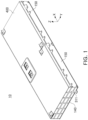
- FIG. 1 is a perspective diagram illustrating a battery module according to an example embodiment.
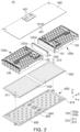
- FIG. 2 is an exploded perspective diagram illustrating a battery module according to an example embodiment.
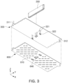
- FIG. 3 is a diagram illustrating a state in which a cooling plate is coupled to a lower cover.
- the battery module 10 may include a plurality of sub-modules 100, a connection member 200 disposed between the sub-modules 100, a lower cover 300 and an upper cover 400.
- the lower cover 300 and the upper cover 400 may support the sub-modules 100.
- the battery module 10 may further include a cooling plate 600 for cooling the battery module 10.
- the plurality of sub-modules 100 may, for example, include a first sub-module 100a and a second sub-module 100b arranged adjacent to each other in a first direction, e.g., an X-axis direction, with the connection member 200 disposed between them.
- the first sub-module 100a and the second sub-module 100b may be assembled together and may form at least a portion of one battery module 10.
- connection members 200 may be disposed between two of the plurality of sub-modules 100.
- a connection member 200 may be disposed between the first sub-module 100a and the second sub-module 100b disposed side by side in the first direction (X-axis direction).
- connection member 200 may have a shape of a partitioner extending in a second direction (Y-axis direction) perpendicular to the first direction (X-axis direction).
- the connection member 200 may be formed of a material having a predetermined level of rigidity so as to structurally support the first sub-module 100a and the second sub-module 100b.
- the connection member 200 may include a metal material such as aluminum or stainless steel.
- the first sub-module 100a and the second sub-module 100b may be coupled to opposite sides of the connection member 200, respectively.
- the first sub-module 100a may be fastened to at least one portion of a first side of the connection member 200
- the second sub-module 100b may be fastened to at least one portion of a second side of the connection member 200.
- the second side of the connection member 200 may be opposite to the first side of the connection member 200. Accordingly, the first sub-module 100a and the second sub-module 100b may be fixed to each other via the connection member 200.
- connection member 200 may work as a reference point for assembling the sub-modules 100. That is, the connection member 200 may partition a space in the battery module 10 in which each sub module 100 is accommodated, and may guide a position in which the sub module 100 is disposed.
- the battery module 10 may include lower cover 300 and upper cover 400 for supporting the plurality of sub-modules 100.
- the integrally formed lower cover 300 may be disposed to cover the lower surfaces of the plurality of sub-modules 100
- the integrally formed upper cover 400 may be disposed to cover the upper surfaces of the plurality of sub-modules 100.
- the lower cover 300 and the upper cover 400 may be integrally formed to stably support the plurality of sub-modules 100 .
- the battery module 10 may include a cooling plate 600 for cooling the battery modules.
- the cooling plate 600 may be coupled to the lower cover 300 and may absorb thermal energy generated by the sub-modules 100a and 100b.
- the cooling plate 600 may include a cooling frame 610 forming a flow path 620.
- the cooling frame 610 may form a structure of the cooling plate 600 and may be combined with the lower cover 300 and may form a flow path 620 which may be a path through which a refrigerant can flow.
- Any suitable coupling method may be used between the cooling frame 610 and the lower cover 300, such as, for example, welding, brazing, roll-bonding, thermal fusion, filler bonding, friction welding, or a physical fastening method through a separate fastening member. These methods may be applied alone or in combination with each other.
- the flow path 620 may be formed on one surface of the cooling frame 610.
- the cooling frame 610 may have a structure in which at least a portion thereof is recessed in a downward direction (e.g., in a negative Z-axis direction), and as the cooling frame 610 is coupled to the lower cover 300, a flow path 620 through which refrigerant can flow may be formed in the space defined between the recessed portion of the cooling frame 610 and the lower cover 300.
- FIG. 2 only illustrates an example shape of the flow path 620, and the flow path 620 may be formed in the cooling frame 610.
- a portion of the cooling plate 600 may be shaded, which is only for distinguishing a portion in which the refrigerant may flow and a portion in which the refrigerant does not flow in the flow path 620.
- the shading does not indicate that the shaded portion and the non-shaded portion are separate members.
- the cooling plate 600 in FIG. 2 may have an integrated cooling frame 610 and a flow path 620 formed on at least a portion of the cooling frame 610. The shading is applied in FIGS. 5 to 11 for the same reasons as indicated above for FIG. 2 .
- the refrigerant flowing through the flow path 620 may be any suitable cooling fluid.
- the refrigerant flowing through the flow path 620 may be, for example, cooling water.
- the refrigerant flowing into the cooling plate 600 may absorb thermal energy generated in the first and second sub-modules 100a and 100b for cooling the first and second sub-modules 100a and 100b.
- the cooling plate 600 may include a guide 630 for guiding the flow of the refrigerant.
- the guide 630 may be formed such that a portion of the cooling frame 610 may protrude in a direction toward the lower cover 300 in the flow path 620.
- the guide 630 may be in contact with the lower cover 300. Accordingly, the refrigerant may not pass through the guide 630 and may flow along the circumference of the guide 630. Accordingly, the flow path or flow rate of the refrigerant may be determined by appropriately designing the shape of the guide 630.
- the shape of the guide 630 may be configured in various manners.
- at least a portion of the guide 630 may have a shape of a protrusion extending in a direction oblique with respect to the first direction (X-axis direction) in which the first sub-module 100a and the second sub-module 100b oppose each other.
- the shape of the guide 630 is not limited to the example illustrated in the drawings.
- the flow rate, cooling efficiency, and pressure drop of the refrigerant flowing through the flow path 620 may vary.
- the guide 630 may, for example, have a shape that optimizes the flow of the cooling fluid for enhance heat removal. A specific shape of the guide 630 will be described later.
- the cooling frame 610 or the lower cover 300 may include a plurality of ports 310 through which refrigerant flows in and out.
- the lower cover 300 may include a first port 311 and a second port 312 communicating with the flow path 620 of the cooling plate 600.
- the first port 311 may be an inlet for the refrigerant
- the second port 312 may be an outlet through which the refrigerant may be discharged. That is, the refrigerant may flow into the first port 311, may flow along the flow path 620 formed by the cooling frame 610, and may be discharged to the outside of the battery module 10 through the second port 312.
- FIG. 2 illustrates a configuration according to which the first and second ports 311 and 312 are disposed on opposite ends of the lower cover 300.
- the first port 311 and the second port 312 may be disposed in the cooling frame 610.
- a plurality of ports 310 may be disposed.
- the battery module 10 may include a single first port 311 and a single second port 312, and in this case, the refrigerant flowing into the first port 311 may cool both the first sub-module 100a and the second sub-module 100b.
- a plurality of first ports 311 and a plurality of second ports 312 may be disposed such that independent cooling flow paths may be formed for each of the sub-modules 100a and 100b.
- both the connection member 200 and the cooling plate 600 may be coupled to the lower cover 300.
- the connection member 200 may be coupled to one surface of the lower cover 300 and the cooling plate 600 may be coupled to the other surface of the lower cover 300.
- the cooling plate 600 may include one or more avoidance portions 640 not to interfere with the coupling structure of the connection member 200 and the lower cover 300.
- the avoidance portion 640 may be an opening penetrating through the cooling frame 610.
- One or more avoidance portions 640 may be provided to correspond to positions in which the connection member 200 and the lower cover 300 are coupled to each other.
- the lower cover 300 may include a fastening portion 321 coupled to the connection member 200, and the fastening portion 321 may be exposed in a downward direction (e.g., a negative Z-axis direction) of the battery module 10 through the avoidance portion 640.
- the battery module 10 may include a fastening member 322 for coupling the lower cover 300 to the connection member 200.
- the fastening portion 321 of the lower cover 300 may have a hole shape into which the fastening member 322 may be inserted.
- the fastening member 322 may pass through the fastening portion 321 of the lower cover 300 and may be fastened to the connection member 200, and the plurality of fastening members 322 may be connected to the cooling frame 610 corresponding to the position to which the avoidance portion 640 is fastened.
- the avoidance portion 640 may be disposed to oppose the connection member 200 with the lower cover 300 therebetween.
- the fastening portion 321 of the lower cover 300 may be exposed through the avoidance portion 640, and the fastening member 322 may be inserted into the exposed fastening portion 321 and may be coupled to the connection member 200.
- At least a portion of the flow path 620 may be formed between the plurality of avoidance portions 640. That is, a cooling flow path may be formed between the avoidance portions 640, and accordingly, at least a portion of the refrigerant flowing into the cooling plate 600 may flow between the plurality of avoidance portions 640.
- the flow path 620 may be configured to cover the entirety of the plurality of sub-modules 100.
- the flow path 620 of the cooling plate 600 may have a cooling region opposing the lower surface of the first sub-module 100a and the lower surface of the second sub-module 100b to cool both the first sub-module 100a and the second sub-module 100b. That is, the cooling plate 600 of the battery module 10 may be configured to have an integrated cooling structure for cooling the entirety of the plurality of sub-modules 100.
- a heat dissipation member 500 may be disposed between the lower cover 300 and the plurality of sub-modules 100.
- One surface of the heat dissipation member 500 may be disposed to be in contact with the sub-module 100 and the other surface opposite to the one surface may be in contact with the lower cover 300.
- the heat dissipation member 500 may be provided with a thermal adhesive.
- the heat dissipation member 500 may fill a space between the sub module 100 and the lower cover 300 such that heat transfer by conduction may be actively performed. Accordingly, heat dissipation efficiency of the battery module 10 may be increased.
- the battery module 10 may include an upper cover 400 covering the upper portion of the sub-module 100.
- the upper cover 400 may be integrally formed to simultaneously support the plurality of sub-modules 100.
- the upper cover 400 may have an opening 401 to expose a terminal portion of the sub-module 100 (e.g., 122 in FIG. 4 ) or a portion of the sensing module of the sub-module 100.
- Each sub-module 100 may include a plurality of battery cells and may be configured to store or discharge electrical energy.
- a plurality of sub-modules 100 may be electrically connected to each other and may output design power values required for the battery module.
- the two sub-modules 100 opposing each other with the connection member 200 interposed therebetween may be connected to each other in series or in parallel through terminal portions (e.g., 122 in FIG. 4 ).
- the plurality of sub-modules 100 may be electrically isolated from each other.
- the two sub-modules 100 opposing each other with the connection member 200 interposed therebetween may be electrically separated from each other, and the terminal portion of each sub-module 100 (e.g., 122 in FIG. 4 ) may be configured to be electrically connected to another neighboring battery module 10.
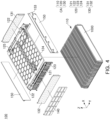
- FIG. 4 is an exploded perspective diagram illustrating a sub-module 100 included in a battery module 10 according to an example embodiment. Since the sub-module 100 described with reference to FIG. 4 may correspond to one of the first sub-module 100a and the second sub-module 100b previously described with reference to FIGS. 1 to 3 , overlapping descriptions may be omitted.
- the battery module 10 may include a plurality of sub-modules 100. At least one of the plurality of sub-modules 100 included in the battery module 10 may include a cell assembly CA and a plurality of protective covers 140 and 150 protecting the cell assembly CA.
- the protective covers 140 and 150 may include an end cover 140 covering at least one side of the cell assembly CA and one or more side covers 150.
- the cell assembly CA may include a cell stack 110 including battery cells 1000 stacked in one direction (e.g., the Y-axis direction in FIG. 4 ), a busbar assembly 120 electrically connected to the cell stack 110, and an insulating cover 130 coupled to the busbar assembly 120.
- the cell stack 110 may include a plurality of battery cells 1000 electrically connected to each other.
- the plurality of battery cells 1000 may be stacked in one direction (e.g., the Y-axis direction).
- the stacking direction of the battery cells 1000 included in the cell stack 110 may be referred to as a "second direction” or a "cell stacking direction.”
- the busbar assembly 120 may include a plurality of busbars 121 electrically connecting the battery cells 1000 of the cell stack 110 to each other and a support frame supporting the busbars 121.
- the busbar 121 may be formed of a conductive material and may electrically connect the plurality of battery cells 1000 to each other.
- the busbar 121 may be electrically connected to the battery cell 1000 while being fixed to the support frame.
- the support frame may support the busbar 121 to be stably connected to the battery cell 1000.
- the support frame may include a non-conductive material (e.g., plastic) having a predetermined stiffness and may structurally support the plurality of busbars 121.
- the support frame may oppose at least one side of the cell stack 110.
- the support frame may include a busbar frame 123 opposing the cell stack 110 in a first direction (X-axis direction) and supporting the busbar 121, and a connection frame 124 opposing the cell stack 110 in the third direction (Z-axis direction) and connected to the busbar frame 123.
- the second direction may be perpendicular to the first direction
- the third direction may be perpendicular to both the first and second directions.
- a sensing module 125 for sensing the electrical and thermal states of the battery cells 1000 may be disposed on the connection frame 124. Voltage information or temperature information sensed by the sensing module 125 may be transmitted to the outside of the sub-module 100 and may be used to control the battery module 10.
- the cell assembly CA may include the insulating cover 130 covering at least one surface of the busbar assembly 120.
- the insulating cover 130 may include a non-conductive material and may prevent the busbar 121 of the busbar assembly 120 from being unintentionally shorted with other components.
- An end cover 140 may be disposed on the outermost side of one side of the sub module 100.
- the end cover 140 may include a rigid material (e.g., a metal material such as aluminum) and may protect the cell assembly CA from external impact.
- the end cover 140 In a state in which the sub-module 100 is coupled to the connection member (e.g., 200 in FIG. 2 ) and the lower cover (e.g., 300 in FIG. 2 ), the end cover 140 may be spaced apart from the connection member 200 and may be disposed on one of the edges of the lower cover 300.
- a plurality of insulating covers 130 of the cell assembly CA may be provided.
- the sub module 100 may include a first insulating cover 131 electrically separating the connecting member 200 and the busbar assembly 120 from each other, and a second insulating cover 132 electrically separating the end cover 140 and the busbar assembly 120 from each other.
- the first insulating cover 131 may be disposed between the connection member 200 and the busbar 121 and may electrically separate the components from each other.
- the second insulating cover 132 may be disposed between the end cover 140 and the busbar 121 and may electrically separate the components from each other.
- the insulating cover 130 may be coupled to the busbar assembly 120.
- each of the first insulating cover 131 and the second insulating cover 132 may be inserted into and fixed to the busbar frame 123.
- the insulating cover 130 may be fixed to the busbar frame 123 through a fastening member.
- the sub module 100 may include a side cover 150 opposing at least one side of the cell stack 110.
- a pair of side covers 150 may be provided to cover different surfaces of the cell stack 110.
- the pair of side covers 150 may be coupled to the end cover 140 and the connection member 200, may form a side surface of the sub module 100 and may protect the cell stack 110 from an external environment.
- the side cover 150 may oppose the cell stack 110 in a different direction from the end cover 140.
- the side cover 150 may be disposed to oppose the cell stack 110 in the second direction (Y-axis direction)
- the end cover 140 may be disposed to oppose the cell stack 110 in the first direction (X-axis direction) with the busbar assembly 120 and the second insulating cover 132 interposed therebetween.
- the end cover 140, the pair of side covers 150, and the first insulating cover 131 may form four surfaces of the sub module 100.
- the end cover 140 may be coupled to one end, and the connection member 200 of the battery module 10 may be coupled to the other end opposite to one side.
- the busbar assembly 120 may also be coupled to the side cover 150.
- the side cover 150 may further include a connection portion 153 which may be structurally connected to an external component of the battery module 10.
- the connection portion 153 may have a structure protruding from the surface of the side cover 150 in a second direction (Y-axis direction).
- the battery module 10 may be coupled to an external component (e.g., a battery pack housing in which the plurality of battery modules 10 are accommodated) through the connection portion 153 of the side cover 150.
- the lower surface of the sub-module 100 may be configured such that the cell stack 110 may be exposed.
- the sub-module 100 may not have a cover member on a lower surface thereof, and accordingly, the cell stack 110 may be in direct contact with an external component of the sub-module 100 (e.g., the lower cover 300 or the heat dissipation member 500 of the battery module 10 illustrated in FIG. 2 ). Accordingly, heat may be smoothly discharged from the cell stack 110 toward the lower portion of the sub-module 100, such that heat dissipation efficiency of the sub-module 100 may be increased.
- an end cover 140 may be disposed in an outermost portion of one side and a first insulating cover 131 may be disposed in an outermost portion of the other side. That is, one sub-module 100 may include a first surface on which the insulating cover 131 is disposed and a second surface on which the end cover 140 is disposed. For example, referring to FIG. 4 , the first surface of one sub-module 100 may be closed with an insulating cover 131, and the second surface opposite to the first surface may be closed with an end cover 140.
- the two sub-modules 100 disposed to oppose each other with the connection member 200 interposed therebetween may be disposed such that the first surfaces thereof may oppose the connection member 200.
- the first sub-module 100a may be coupled to the connection member 200 such that the first surface on which the insulating cover 130 is disposed may oppose the connection member 200
- the second sub-module 100b may be coupled to the connection member 200 such that the first surface on which the insulating cover 130 is disposed may oppose the connection member 200.
- the end covers 140 of each sub-module 100 may form the front and rear outer surfaces
- the side covers 150 coupled to the end cover 140 may form the side outer surfaces
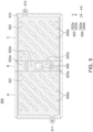
- FIG. 5 is a diagram illustrating cooling plate 600 according to an example embodiment, viewed from above.
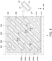
- FIG. 6 is an enlarged diagram illustrating a portion of the cooling plate 600 in FIG. 5 according to an example embodiment.
- FIG. 7 is a diagram illustrating an example in which a shape of an avoidance portion 640 is partially changed in the cooling plate 600 in FIG. 5 . Since the cooling plate 600 described with reference to FIGS. 5 and 6 may be similar to the cooling plate 600 previously described with reference to FIGS. 1 to 3 , overlapping descriptions may not be provided.
- the cooling plate 600 may be configured to cool the entirety of the plurality of sub-modules (e.g., 100 in FIG. 2 ) included in the battery module (e.g., 10 in FIGS. 1 and 2 ).
- the cooling plate 600 may cool first and second regions A and C corresponding to the first sub-module 100a and the second sub-module 100b, respectively, and a third region B corresponding to a portion in which a connecting member (e.g., 200 in FIGS. 2 and 3 ) is disposed.
- the flow path of the cooling plate 600 may include a first flow path 621 for cooling the first region A, a second flow path 623 for cooling the second region C, and third flow path 622 for cooling the third region B.
- the first flow path 621, the third flow path 622, and the second flow path 623 may be arranged in a direction parallel to the first direction (e.g., the X-axis direction) in which the first sub-module 100a and the second sub-module 100b are arranged.
- the first flow path 621 of the cooling plate 600 may communicate with the second flow path 623 through the third flow path 622.
- the refrigerant flowing from the first port 311 may cool the first sub-module 100a while flowing along the first flow path 621.
- the refrigerant passing through the first flow path 621 may flow to the second flow path 623 through the third flow path 622.
- the refrigerant may cool the second sub-module 100b while flowing along the second flow path 623 and may exit through the second port 312.
- the cooling frame 610 forming the first to third flow paths 621, 622, and 623 may be integrally formed, and accordingly, the cooling plate 600 having a structurally simple and stable cooling performance may be implemented.
- Guide 630 may be disposed in the first flow path 621 and the second flow path 623.
- the guide 630 may guide the flow of the refrigerant.
- the guide 630 may include a plurality of guide protrusions 630a and 630b arranged in a predetermined pattern.
- the pattern formed by the guide protrusions 630a and 630b may be varied depending on the cooling performance requirements of the battery module 10.
- the cooling plate 600 may include a plurality of guide protrusions 630a and 630b forming an oblique pattern with respect to a first direction (X-axis direction) such that the refrigerant which flow in may spread swiftly and widely.
- the refrigerant flowing in through the first port 311 may spread swiftly and evenly to the first flow path 621 by the guide protrusions 630a disposed in an oblique pattern in the first flow path 621. Accordingly, a decrease of pressure may be prevented while the refrigerant flows through the flow path and may secure high cooling performance.
- the guide 630 may include a guide protrusion groups 631, 632, 633, and 634, a plurality of groups of a plurality of guide protrusions 634a, 634b, or the like, arranged in an oblique direction with respect to one edge of the cooling frame 610.
- a plurality of guide protrusion groups 631, 632, 633, and 634 may be formed.
- the guide 630 may include a plurality of guide protrusion groups 631, 632, 633, and 634, each having a different number of guide protrusions.
- the first guide protrusion group 631 may include a guide protrusion
- the second guide protrusion group 632 may include two guide protrusions
- the third guide protrusion group 633 may include three guide protrusions.
- the guide protrusions included in one of the groups of guide protrusions may have different shapes.
- a portion of guide protrusions 635a may have a circular shape
- the other portion of the guide protrusions 635b may have curved ends and a flat central portion.
- the guide protrusions included in a group of guide protrusions may be spaced apart from each other in one direction.
- the guide protrusions 634a, 634b, or the like, of the fourth guide protrusion group 634 may be spaced apart to have a first distance d1 therebetween, and may be disposed in the fourth direction having a predetermined angle (a) with the first direction (X-axis direction).
- the predetermined angle may be an acute angle.
- One of the guide protrusion groups may be spaced apart from another guide protrusion group with a predetermined distance therebetween.
- the guide protrusion 634a included in the fourth guide protrusion group 634 and the guide protrusion 625b included in the fifth guide protrusion group 635 may be spaced apart from each other to have a second distance d2 therebetween.
- the first distance d1 may be equal to or smaller than the second distance d2.
- the refrigerant may smoothly flow in the fourth direction.
- At least one of the plurality of guide protrusions may include a flat portion FP having a surface parallel to the fourth direction and a curved portion CP disposed on both ends of the flat portion FP.
- one of the guide protrusions may include a pair of flat portions FP having an inclination with respect to a first direction (X-axis direction) and a curved portion CP connecting the pair of flat portions FP to each other.
- the plurality of guide protrusions included in one of the guide protrusion groups may be arranged such that the curved portions CP may oppose each other. Due to this arrangement structure, a decrease of pressure may be prevented while the refrigerant flows between the plurality of guide protrusions, and an effect of facilitating the diffusion of the refrigerant may be obtained.
- a plurality of guides 630 may be disposed in the second flow path 623 as well.
- the guide 630 disposed on the second flow path 623 may have a pattern similar to that of the guide 630 disposed on the first flow path 621.
- a plurality of guide protrusions 630b forming a pattern in a direction parallel to the fourth direction described above may be formed in the second flow path 623.
- the fourth direction which is the pattern direction of the guide, may be substantially parallel to a diagonal line connecting the lower left corner (hereinafter referred to as a first corner) and the upper right corner (hereinafter referred to as a second corner) of the first region A and the second region C.
- the first port 311 through which the refrigerant flows may be disposed adjacent to the first corner of the first region A.
- the second port 312 through which the refrigerant is discharged may be disposed adjacent to the second corner of the second region C.
- the guide 630 may reduce the flow friction in the flow process until the refrigerant flowing into the first port 311 is discharged to the second port 312, thereby reducing the pressure of the refrigerant. Therefore, since the flow of the refrigerant may be smoothly maintained even with a small amount of energy, energy required for cooling the battery module 10 may be saved.
- the third flow path 622 disposed between the first flow path 621 and the second flow path 623 may have a plurality of flow paths such that the refrigerant may smoothly flow through the first flow path 621 and the second flow path 623.
- the cooling frame 610 may have a plurality of avoidance portions 640 avoiding a portion in which the connection member 200 and the lower cover are coupled to each other, and a flow path may be formed between the avoidance portions 640.
- the third flow path 622 may include a side flow path 622a disposed between the avoidance portion 640 and the edge of the cooling frame 610 and a center flow path 622b disposed between the side flow path 622a and the plurality of avoidance portions 640.
- the cooling plate 600 has a plurality of flow paths between the avoidance portions 640, interference with the coupling structure of the battery module 10 may be prevented and a smooth cooling flow path may be secured. Also, by forming a flow path by avoiding the portion in which the fastening member (e.g., 322 in FIG. 3 ), the refrigerant may be prevented from leaking through the fastening portion.
- the fastening member e.g., 322 in FIG. 3
- the specific shape of the guide 630 is not limited to the above example.
- the guide 630 formed in the first flow path 621 and the guide 630 formed on the second flow path 623 may include a plurality of guide protrusions arranged in different patterns.
- connection flow paths 622a may be formed along both ends of the avoidance portion 640 in the second direction (Y-axis direction), respectively.
- the configurations other than the shape of the avoidance portion 640 and the connection flow paths 622a may correspond to those of the cooling plate 600 in FIG. 5 .
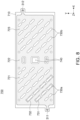
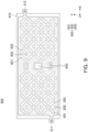
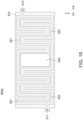
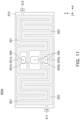
- FIGS. 8 to 11 are diagrams illustrating a cooling plate according to another example embodiment, viewed from above.
- the configurations other than the shape of the guide may correspond to those of the cooling plate described with reference to FIGS. 1 to 6 , and accordingly, overlapping descriptions may not be provided.
- guides 730a and 730b of a cooling plate 700 may include a plurality of guide protrusion groups 731 and 732 forming a pattern in a direction different from the fourth direction described with reference to FIG. 6 .
- the guides 730a and 730b may include a plurality of guide protrusion groups 731 and 732 formed by a plurality of guide protrusions arranged in a fifth direction perpendicular to the fourth direction.
- the refrigerant flowing in through the first port 311 may diffuse widely into the first flow path 721 by the guide 730a having a pattern in the fifth direction. Accordingly, the entire first region may be rapidly cooled, which may be advantageous.
- the guide 830 of the cooling plate 800 may have a pattern in which guide protrusions 831, 832, and 833 having different shapes and orientations may be alternately disposed.
- the guide 830 may include a first guide protrusion 831 extending in the fourth direction described above with reference to FIG. 6 , a second guide protrusion 832 extending in the fifth direction described with reference to FIG. 8 , and a third guide protrusion 833 having an approximately elliptical (or oval) shape.
- the first guide protrusion 831, the second guide protrusion 832, and the third guide protrusion 833 may be alternately arranged in various manners.
- the first guide protrusion 831 and the second guide protrusion 832 may be alternately arranged in the first direction (X-axis direction) and the second direction (Y-axis direction), and a third guide protrusion 833 may be disposed therebetween.
- the third guide protrusion 833 may be disposed between two first guide protrusions 831 and between two second guide protrusions 832.
- the refrigerant may be induced to stably flow in the first direction (X-axis direction) and the second direction (Y-axis direction), and a decrease of pressure due to friction may be prevented.
- the guides of the cooling plates 900a and 900b may be formed in a continuous wall shape to form flow paths 921 and 922 having a tubular shape.
- the guide may be configured such that the refrigerant flowing in through the first port 311 may flow along the first flow path 921 and the second flow path 922 separated from each other and may be discharged through the second port 312.
- the first flow path 921 may form a first path through which the refrigerant may flow.
- the second flow path 922 may be partitioned from the first flow path and may form a second flow path through which the refrigerant may flow. Accordingly, the refrigerant flowing in through the first port 311 may flow along two or more different paths, and may cool the battery module 10, and may be discharged through the second port 312.
- first flow path 921 and the second flow path 922 may have paths bent multiple times, such that the refrigerant may flow evenly throughout regions corresponding to lower portions of the first sub-module and the second sub-module.
- a portion of the first flow path 921 and a portion of the second flow path 922 may be spaced apart in the second direction (Y-axis direction) with the avoidance portion 940 of the cooling plates 900a and 900b interposed therebetween.
- a portion of the first flow path 921 and a portion of the second flow path 922 may be formed along the edge of the cooling frame with the avoidance portion 940 interposed therebetween.
- the first flow path 921 may include a first sub-flow path 921a and a second sub-flow path 921b spaced apart from each other with at least the avoidance portion 940 interposed therebetween.
- the first sub-flow path 921a and the second sub-flow path 921b may pass through the avoidance portion 940, may merge into one path and may form the first flow path 921.
- the second flow path 922 may include a third sub-flow path 922a and a fourth sub-flow path 922b spaced apart from each other with at least one avoidance portion 940 interposed therebetween.
- the third sub-flow path 922a and the fourth sub-flow path 922b may pass through the avoidance portion 940, may merge and may form the first flow path 922.
- a method of manufacturing a battery module may include a sub-module manufacturing step of manufacturing a plurality of sub-modules 100, a connecting step of connecting the manufactured sub-modules 100 to each other via a connection member 200, and a cover step of closing the upper and lower portions of the connected sub-modules by covering the portions with a case (e.g., an upper cover and a lower cover).
- a case e.g., an upper cover and a lower cover
- a sub-module may be a sub-unit included in at least a portion of a battery module, and a battery module may be manufactured by assembling a plurality of sub-modules.
- the plurality of sub-modules 100 manufactured as above may be assembled with each other via the connection member 200.
- the plurality of sub-modules 100 connected to each other by the connection member 200 may be combined with the upper cover 400 and the lower cover 300 covering the upper and lower portions.
- the plurality of sub-modules 100a and 100b may be seated on the lower cover 300 which may integrally support the components.
- a heat dissipation member 500 may be applied to an upper surface of the lower cover 300.
- the connection member 200 disposed between the plurality of sub-modules 100a and 100b may be fastened to the lower cover 300 and the upper cover 400. In this case, a bolting coupling method using a separate fastening member 322 may be applied.
- the method of manufacturing the battery module 10 may further include a cooling plate coupling step of coupling the cooling plate 600 for cooling the sub-modules 100 to the lower cover 300.
- the cooling plate 600 may be coupled to the lower cover 300 by welding, brazing, roll-bonding, thermal fusion, filler bonding, or friction welding.
- the step of assembling the cooling plate may already be performed before assembling the plurality of sub-modules 100 with the lower cover 300.
- the coupling of the cooling plate 600 may be performed simultaneously in or after the process of coupling the plurality of sub-modules 100 to the lower cover 300.
- the manufacturing method of the battery module 10 is not limited to the above, and for example, the method may further include a step of connecting sensing modules (125 in FIG. 3 ) for sensing the state of the sub-modules 100 to each other, or a step of connecting a connector to the terminal unit (122 in FIG. 3 ) of the sub-modules 100.
- the cooling plate included in the battery module may form a cooling flow path for cooling the entirety of the plurality of sub-modules without interfering with a coupling structure of a connection member for connecting the plurality of sub-modules to each other.
- the cooling plate may guide the flow of the refrigerant through a guide having a predetermined pattern, thereby reducing a decrease of pressure generated during the flow process and rapidly cooling a plurality of sub-modules including a large number of battery cells.
Landscapes
- Chemical & Material Sciences (AREA)
- Chemical Kinetics & Catalysis (AREA)
- Electrochemistry (AREA)
- General Chemical & Material Sciences (AREA)
- Engineering & Computer Science (AREA)
- Manufacturing & Machinery (AREA)
- Aviation & Aerospace Engineering (AREA)
- Secondary Cells (AREA)
- Battery Mounting, Suspending (AREA)
Abstract
Description
- Example embodiments of the present disclosure relate to a battery module.
- A battery module including submodules with battery cells has been developed and applied as an eco-friendly power source for an electric automobile such as a hybrid vehicle. A secondary battery may be charged and discharged differently from primary batteries, and has attracted attention as a power source of various mobile devices and electric vehicles. For example, a battery module may be formed by connecting a plurality of secondary batteries using a high energy density non-aqueous electrolyte, and the battery module may be used as a power source for an electric vehicle.
- When a temperature of a secondary battery is higher than an appropriate temperature, performance of the secondary battery may deteriorate, and in severe cases, there may be a risk of explosion or ignition. In particular, to configure a high capacity and large-area battery module, the number of required battery cells may increase, but as a plurality of battery cells are concentrated in a small space, temperature of the battery module may increase rapidly.
- Therefore, to stably charge and discharge a high-capacity battery module including a plurality of battery cells, a cooling structure for efficiently controlling a temperature of the battery module may be necessary.
- An example embodiment of the present disclosure is to provide a cooling plate for swiftly and effectively cooling a battery module having high capacity and a battery module including the same.
- An example embodiment of the present disclosure is to provide a cooling plate having a structure corresponding to a structure in which a plurality of sub-modules are coupled, and a battery module including the same.
- According to an example embodiment of the present disclosure, an eco-friendly power source, such as a battery module for a transportation vehicle, includes a first sub-module and a second sub-module, each of the first and second sub-modules including a plurality of battery cells; a connection member having a first side coupled to the first sub-module and a second side coupled to the second sub-module, the second side being opposite to the first side; and a cooling plate configured to cool the first and second sub-modules.
- The battery module may include a lower cover supporting the first sub-module and the second sub-module. The cooling plate may couple to the lower cover and forming a flow path through which a refrigerant can flow, wherein at least a portion of the flow path is disposed to oppose the connection member with the lower cover interposed therebetween.
- The flow path may include a first flow path disposed below the first sub-module; a second flow path disposed below the second sub-module; and a third flow path connecting the first flow path to the second flow path, wherein at least a portion of the third flow path is disposed to oppose the connection member with the lower cover interposed therebetween.
- The cooling plate includes a guide disposed in the flow path and configured to guide a flow of the refrigerant.
- The guide may include a plurality of guide protrusions protruding in a direction toward the lower cover and in contact with the lower cover.
- The first sub-module and the second sub-module may be disposed to oppose each other in a first direction, and at least one of the plurality of guide protrusions includes a flat portion inclined with respect to the first direction; and curved portions disposed on both ends of the flat portion.
- The first sub-module and the second sub-module may be disposed to oppose each other in a first direction, and the guide may include one or more guide protrusion groups consisting of a plurality of guide protrusions arranged in a second direction different from the first direction.
- The one or more guide protrusion groups may include a first guide protrusion group and a second guide protrusion group, the plurality of guide protrusions included in the first guide protrusion group may be spaced apart from each other by a first distance, one of the plurality of guide protrusions included in the first guide protrusion group is spaced apart from the second guide protrusion group with a second distance therebetween, and the first distance may be less than or equal to the second distance.
- The first flow path may communicate with the second flow path through the third flow path.
- The connection member may be coupled to one surface of the lower cover, and the cooling plate may be coupled to the other surface opposite to the one surface of the lower cover.
- The lower cover may include a fastening portion fastened to the connection member, and the cooling plate may include an avoidance portion preventing contact between the fastening portion and the refrigerant.
- The avoidance portion may have an opening shape penetrating through the cooling plate between a first flow path disposed below the first sub-module and a second flow path disposed below the second sub-module.
- The flow path may include a first flow path forming a first path through which the refrigerant can flow; and a second flow path forming a second path partitioned from the first path, and a portion of the first flow path and a portion of the second flow path are disposed spaced apart from each other with the avoidance portion interposed therebetween.
- A plurality of the avoidance portions may be disposed in a length direction of the connection member, and at least one of the first flow path and the second flow path may include a first sub-flow path and a second sub-flow path spaced apart from each other with at least one of the plurality of avoidance portions interposed therebetween.
- A heat dissipation member may be disposed on the one surface of the lower cover.
- According to an example embodiment of the present disclosure, a battery module includes a first sub-module and a second sub-module including a plurality of battery cells, respectively; a lower cover supporting the first sub-module and the second sub-module; a connection member disposed between the first sub-module and the second sub-module; and a cooling plate coupled to the lower cover and forming a flow path through which a refrigerant can flow, wherein the lower cover includes a fastening portion fastened to the connection member, and the cooling plate includes an avoidance portion exposing the fastening portion.
- The cooling plate may include a plurality of avoidance portions, the first sub-module and the second sub-module may be disposed to oppose each other in a first direction with the connection member interposed therebetween, and the plurality of avoidance portions may be spaced apart from each other in a second direction perpendicular to the first direction.
- The cooling plate may include a flow path forming a flow path through which a refrigerant can flow, and at least a portion of the flow path may be disposed between the plurality of avoidance portions.
- The flow path may include a first flow path for cooling the first sub-module; a second flow path for cooling the second sub-module; and a third flow path connecting the first flow path to the second flow path, and at least a portion of the third flow path is disposed between the plurality of avoidance portions.
- The battery module may further include a fastening member penetrating through the fastening portion and fastened to the connection member.
- According to another aspect of the present disclosure, a battery module includes a first sub-module including a first plurality of battery cells; a second sub-module including a second plurality of battery cells, a connection member having a first side coupled to the first sub-module and a second side coupled to the second sub-module, the second side being opposite to the first side; and a cooling plate configured to cool the first and second sub-modules.
- The above and other aspects, features, and advantages of the present disclosure will be more clearly understood from the following detailed description, taken in conjunction with the accompanying drawings, in which:
-
FIG. 1 is a perspective diagram illustrating a battery module according to an example embodiment of the present disclosure; -
FIG. 2 is an exploded perspective diagram illustrating a battery module according to an example embodiment of the present disclosure; -
FIG. 3 is an exploded perspective diagram illustrating a battery cell assembly according to an example embodiment of the present disclosure; -
FIG. 4 is an exploded perspective diagram illustrating a sub-module included in a battery module according to an example embodiment of the present disclosure; -
FIG. 5 is a diagram illustrating a cooling plate according to an example embodiment of the present disclosure, viewed from above; -
FIG. 6 is an enlarged diagram illustrating a portion of the cooling plate inFIG. 5 according to an example embodiment of the present disclosure; -
FIG. 7 is a diagram illustrating an example in which a shape of an avoidance portion is partially changed in the cooling plate inFIG. 5 ; -
FIG. 8 is a diagram illustrating a cooling plate according to another example embodiment of the present disclosure, viewed from above; -
FIG. 9 is a diagram illustrating a cooling plate according to another example embodiment of the present disclosure, viewed from above; -
FIG. 10 is a diagram illustrating a cooling plate according to another example embodiment of the present disclosure, viewed from above; and -
FIG. 11 is a diagram illustrating a cooling plate according to another example embodiment of the present disclosure, viewed from above. - It is to be understood that the terms or words used in this description and the following claims must not be construed to have meanings which are general or may be found in a dictionary. Therefore, considering the notion that an inventor may most properly define the concepts of the terms or words to best explain his or her invention, the terms or words must be understood as having meanings or concepts that conform to the technical spirit of the present disclosure. Also, since the example embodiments set forth herein and the configurations illustrated in the drawings are nothing but a mere example and are not representative of all technical spirits of the present disclosure, it is to be understood that various equivalents and modifications may replace the example embodiments and configurations at the time of the present application.
- In the drawings, same elements will be indicated by same reference numerals. Also, redundant descriptions and detailed descriptions of known functions and elements which may unnecessarily make the gist of the present disclosure obscure will not be provided. In the accompanying drawings, a portion of elements may be exaggerated, omitted or briefly illustrated, and the sizes of the elements do not necessarily reflect the actual sizes of these elements.
- The terms, "include," "comprise," "is configured to," etc. of the description are used to indicate the presence of features, numbers, steps, operations, elements, portions or combination thereof, and do not exclude the possibilities of combination or addition of one or more features, numbers, steps, operations, elements, portions or combination thereof.
- In example embodiments, terms such as an upper side, an upper portion, a lower side, a lower portion, a side surface, a front surface, a rear surface, or the like, are represented based on the directions in the drawings, and may be used differently if the direction of an element is changed.
- The terms "first," "second," and the like may be used to distinguish one element from the other, and may not limit a sequence and/or an importance, or others, in relation to the elements. In a portion of cases, a first element may be referred to as a second element, and similarly, a second element may be referred to as a first element without departing from the scope of the invention in the example embodiments.
-
FIG. 1 is a perspective diagram illustrating a battery module according to an example embodiment.FIG. 2 is an exploded perspective diagram illustrating a battery module according to an example embodiment.FIG. 3 is a diagram illustrating a state in which a cooling plate is coupled to a lower cover. - Referring to
FIG. 2 , thebattery module 10 may include a plurality ofsub-modules 100, aconnection member 200 disposed between thesub-modules 100, alower cover 300 and anupper cover 400. Thelower cover 300 and theupper cover 400 may support thesub-modules 100. Thebattery module 10 may further include acooling plate 600 for cooling thebattery module 10. - In the embodiment of
FIG. 2 the plurality ofsub-modules 100 may, for example, include a first sub-module 100a and a second sub-module 100b arranged adjacent to each other in a first direction, e.g., an X-axis direction, with theconnection member 200 disposed between them. The first sub-module 100a and the second sub-module 100b may be assembled together and may form at least a portion of onebattery module 10. - One or
more connection members 200 may be disposed between two of the plurality ofsub-modules 100. For example, as illustrated inFIG. 2 , aconnection member 200 may be disposed between the first sub-module 100a and the second sub-module 100b disposed side by side in the first direction (X-axis direction). - The
connection member 200 may have a shape of a partitioner extending in a second direction (Y-axis direction) perpendicular to the first direction (X-axis direction). Theconnection member 200 may be formed of a material having a predetermined level of rigidity so as to structurally support the first sub-module 100a and the second sub-module 100b. For example, theconnection member 200 may include a metal material such as aluminum or stainless steel. - The first sub-module 100a and the second sub-module 100b may be coupled to opposite sides of the
connection member 200, respectively. For example, the first sub-module 100a may be fastened to at least one portion of a first side of theconnection member 200, and the second sub-module 100b may be fastened to at least one portion of a second side of theconnection member 200. The second side of theconnection member 200 may be opposite to the first side of theconnection member 200. Accordingly, the first sub-module 100a and the second sub-module 100b may be fixed to each other via theconnection member 200. - In the
battery module 10 including a plurality ofsub-modules 100, theconnection member 200 may work as a reference point for assembling the sub-modules 100. That is, theconnection member 200 may partition a space in thebattery module 10 in which eachsub module 100 is accommodated, and may guide a position in which thesub module 100 is disposed. - The
battery module 10 may includelower cover 300 andupper cover 400 for supporting the plurality ofsub-modules 100. For example, referring toFIG. 2 , the integrally formedlower cover 300 may be disposed to cover the lower surfaces of the plurality ofsub-modules 100, and the integrally formedupper cover 400 may be disposed to cover the upper surfaces of the plurality ofsub-modules 100. Thelower cover 300 and theupper cover 400 may be integrally formed to stably support the plurality ofsub-modules 100 . - The
battery module 10 may include acooling plate 600 for cooling the battery modules. For example, referring toFIG. 2 , thecooling plate 600 may be coupled to thelower cover 300 and may absorb thermal energy generated by the sub-modules 100a and 100b. - The
cooling plate 600 may include acooling frame 610 forming aflow path 620. Thecooling frame 610 may form a structure of thecooling plate 600 and may be combined with thelower cover 300 and may form aflow path 620 which may be a path through which a refrigerant can flow. Any suitable coupling method may be used between the coolingframe 610 and thelower cover 300, such as, for example, welding, brazing, roll-bonding, thermal fusion, filler bonding, friction welding, or a physical fastening method through a separate fastening member. These methods may be applied alone or in combination with each other. - The
flow path 620 may be formed on one surface of thecooling frame 610. For example, referring toFIG. 2 , thecooling frame 610 may have a structure in which at least a portion thereof is recessed in a downward direction (e.g., in a negative Z-axis direction), and as thecooling frame 610 is coupled to thelower cover 300, aflow path 620 through which refrigerant can flow may be formed in the space defined between the recessed portion of thecooling frame 610 and thelower cover 300. However,FIG. 2 only illustrates an example shape of theflow path 620, and theflow path 620 may be formed in thecooling frame 610. - In
FIG. 2 , a portion of thecooling plate 600 may be shaded, which is only for distinguishing a portion in which the refrigerant may flow and a portion in which the refrigerant does not flow in theflow path 620. The shading does not indicate that the shaded portion and the non-shaded portion are separate members. For example, thecooling plate 600 inFIG. 2 may have an integratedcooling frame 610 and aflow path 620 formed on at least a portion of thecooling frame 610. The shading is applied inFIGS. 5 to 11 for the same reasons as indicated above forFIG. 2 . - Referring to
FIG. 2 , the refrigerant flowing through theflow path 620 may be any suitable cooling fluid. The refrigerant flowing through theflow path 620 may be, for example, cooling water. The refrigerant flowing into thecooling plate 600 may absorb thermal energy generated in the first andsecond sub-modules second sub-modules - The
cooling plate 600 may include aguide 630 for guiding the flow of the refrigerant. For example, referring toFIG. 2 , theguide 630 may be formed such that a portion of thecooling frame 610 may protrude in a direction toward thelower cover 300 in theflow path 620. When thecooling frame 610 is coupled to thelower cover 300, theguide 630 may be in contact with thelower cover 300. Accordingly, the refrigerant may not pass through theguide 630 and may flow along the circumference of theguide 630. Accordingly, the flow path or flow rate of the refrigerant may be determined by appropriately designing the shape of theguide 630. - In the
cooling plate 600 according to the example embodiments, the shape of theguide 630 may be configured in various manners. For example, as illustrated inFIG. 2 , at least a portion of theguide 630 may have a shape of a protrusion extending in a direction oblique with respect to the first direction (X-axis direction) in which the first sub-module 100a and the second sub-module 100b oppose each other. However, the shape of theguide 630 is not limited to the example illustrated in the drawings. - Depending on the shape of the
guide 630, the flow rate, cooling efficiency, and pressure drop of the refrigerant flowing through theflow path 620 may vary. Theguide 630 may, for example, have a shape that optimizes the flow of the cooling fluid for enhance heat removal. A specific shape of theguide 630 will be described later. - Referring to
FIGS. 2 and3 , thecooling frame 610 or thelower cover 300 may include a plurality ofports 310 through which refrigerant flows in and out. For example, thelower cover 300 may include afirst port 311 and asecond port 312 communicating with theflow path 620 of thecooling plate 600. Here, thefirst port 311 may be an inlet for the refrigerant, and thesecond port 312 may be an outlet through which the refrigerant may be discharged. That is, the refrigerant may flow into thefirst port 311, may flow along theflow path 620 formed by thecooling frame 610, and may be discharged to the outside of thebattery module 10 through thesecond port 312. - The positioning of the
first port 311 and thesecond port 312 may vary.FIG. 2 illustrates a configuration according to which the first andsecond ports lower cover 300. Alternatively, thefirst port 311 and thesecond port 312 may be disposed in thecooling frame 610. - In the battery module, a plurality of
ports 310 may be disposed. For example, as illustrated inFIG. 2 , thebattery module 10 may include a singlefirst port 311 and a singlesecond port 312, and in this case, the refrigerant flowing into thefirst port 311 may cool both the first sub-module 100a and the second sub-module 100b. - Alternatively, a plurality of
first ports 311 and a plurality ofsecond ports 312 may be disposed such that independent cooling flow paths may be formed for each of the sub-modules 100a and 100b. - In the
battery module 10 according to the example embodiments, both theconnection member 200 and thecooling plate 600 may be coupled to thelower cover 300. For example, theconnection member 200 may be coupled to one surface of thelower cover 300 and thecooling plate 600 may be coupled to the other surface of thelower cover 300. - The
cooling plate 600 may include one ormore avoidance portions 640 not to interfere with the coupling structure of theconnection member 200 and thelower cover 300. Referring toFIGS. 2 and3 , theavoidance portion 640 may be an opening penetrating through thecooling frame 610. - One or
more avoidance portions 640 may be provided to correspond to positions in which theconnection member 200 and thelower cover 300 are coupled to each other. For example, referring toFIG. 3 , thelower cover 300 may include afastening portion 321 coupled to theconnection member 200, and thefastening portion 321 may be exposed in a downward direction (e.g., a negative Z-axis direction) of thebattery module 10 through theavoidance portion 640. - The
battery module 10 may include afastening member 322 for coupling thelower cover 300 to theconnection member 200. Thefastening portion 321 of thelower cover 300 may have a hole shape into which thefastening member 322 may be inserted. Thefastening member 322 may pass through thefastening portion 321 of thelower cover 300 and may be fastened to theconnection member 200, and the plurality offastening members 322 may be connected to thecooling frame 610 corresponding to the position to which theavoidance portion 640 is fastened. - The
avoidance portion 640 may be disposed to oppose theconnection member 200 with thelower cover 300 therebetween. Thefastening portion 321 of thelower cover 300 may be exposed through theavoidance portion 640, and thefastening member 322 may be inserted into the exposedfastening portion 321 and may be coupled to theconnection member 200. - At least a portion of the
flow path 620 may be formed between the plurality ofavoidance portions 640. That is, a cooling flow path may be formed between theavoidance portions 640, and accordingly, at least a portion of the refrigerant flowing into thecooling plate 600 may flow between the plurality ofavoidance portions 640. - In the
cooling plate 600, theflow path 620 may be configured to cover the entirety of the plurality ofsub-modules 100. For example, referring toFIG. 2 , theflow path 620 of thecooling plate 600 may have a cooling region opposing the lower surface of the first sub-module 100a and the lower surface of the second sub-module 100b to cool both the first sub-module 100a and the second sub-module 100b. That is, thecooling plate 600 of thebattery module 10 may be configured to have an integrated cooling structure for cooling the entirety of the plurality ofsub-modules 100. - To improve cooling efficiency, a
heat dissipation member 500 may be disposed between thelower cover 300 and the plurality ofsub-modules 100. One surface of theheat dissipation member 500 may be disposed to be in contact with the sub-module 100 and the other surface opposite to the one surface may be in contact with thelower cover 300. Theheat dissipation member 500 may be provided with a thermal adhesive. Theheat dissipation member 500 may fill a space between thesub module 100 and thelower cover 300 such that heat transfer by conduction may be actively performed. Accordingly, heat dissipation efficiency of thebattery module 10 may be increased. - The
battery module 10 may include anupper cover 400 covering the upper portion of the sub-module 100. Theupper cover 400 may be integrally formed to simultaneously support the plurality ofsub-modules 100. - The
upper cover 400 may have anopening 401 to expose a terminal portion of the sub-module 100 (e.g., 122 inFIG. 4 ) or a portion of the sensing module of the sub-module 100. - Each sub-module 100 may include a plurality of battery cells and may be configured to store or discharge electrical energy.
- In the
battery module 10, a plurality ofsub-modules 100 may be electrically connected to each other and may output design power values required for the battery module. For example, the twosub-modules 100 opposing each other with theconnection member 200 interposed therebetween may be connected to each other in series or in parallel through terminal portions (e.g., 122 inFIG. 4 ). - Conversely, in the
battery module 10, the plurality ofsub-modules 100 may be electrically isolated from each other. For example, the twosub-modules 100 opposing each other with theconnection member 200 interposed therebetween may be electrically separated from each other, and the terminal portion of each sub-module 100 (e.g., 122 inFIG. 4 ) may be configured to be electrically connected to another neighboringbattery module 10. - Hereinafter, sub-modules according to example embodiments will be described with reference to
FIG. 4 . -
FIG. 4 is an exploded perspective diagram illustrating a sub-module 100 included in abattery module 10 according to an example embodiment. Since the sub-module 100 described with reference toFIG. 4 may correspond to one of the first sub-module 100a and the second sub-module 100b previously described with reference toFIGS. 1 to 3 , overlapping descriptions may be omitted. - The
battery module 10 may include a plurality ofsub-modules 100. At least one of the plurality ofsub-modules 100 included in thebattery module 10 may include a cell assembly CA and a plurality ofprotective covers protective covers end cover 140 covering at least one side of the cell assembly CA and one or more side covers 150. - The cell assembly CA may include a
cell stack 110 includingbattery cells 1000 stacked in one direction (e.g., the Y-axis direction inFIG. 4 ), abusbar assembly 120 electrically connected to thecell stack 110, and an insulatingcover 130 coupled to thebusbar assembly 120. - The
cell stack 110 may include a plurality ofbattery cells 1000 electrically connected to each other. In onecell stack 110, the plurality ofbattery cells 1000 may be stacked in one direction (e.g., the Y-axis direction). In the description below, the stacking direction of thebattery cells 1000 included in thecell stack 110 may be referred to as a "second direction" or a "cell stacking direction." - The
busbar assembly 120 may include a plurality ofbusbars 121 electrically connecting thebattery cells 1000 of thecell stack 110 to each other and a support frame supporting thebusbars 121. - The
busbar 121 may be formed of a conductive material and may electrically connect the plurality ofbattery cells 1000 to each other. Thebusbar 121 may be electrically connected to thebattery cell 1000 while being fixed to the support frame. - The support frame may support the
busbar 121 to be stably connected to thebattery cell 1000. The support frame may include a non-conductive material (e.g., plastic) having a predetermined stiffness and may structurally support the plurality ofbusbars 121. - The support frame may oppose at least one side of the
cell stack 110. For example, referring toFIG. 4 , the support frame may include abusbar frame 123 opposing thecell stack 110 in a first direction (X-axis direction) and supporting thebusbar 121, and aconnection frame 124 opposing thecell stack 110 in the third direction (Z-axis direction) and connected to thebusbar frame 123. Here, the second direction may be perpendicular to the first direction, and the third direction may be perpendicular to both the first and second directions. - A
sensing module 125 for sensing the electrical and thermal states of thebattery cells 1000 may be disposed on theconnection frame 124. Voltage information or temperature information sensed by thesensing module 125 may be transmitted to the outside of the sub-module 100 and may be used to control thebattery module 10. - The cell assembly CA may include the insulating
cover 130 covering at least one surface of thebusbar assembly 120. The insulatingcover 130 may include a non-conductive material and may prevent thebusbar 121 of thebusbar assembly 120 from being unintentionally shorted with other components. - An
end cover 140 may be disposed on the outermost side of one side of thesub module 100. Theend cover 140 may include a rigid material (e.g., a metal material such as aluminum) and may protect the cell assembly CA from external impact. In a state in which the sub-module 100 is coupled to the connection member (e.g., 200 inFIG. 2 ) and the lower cover (e.g., 300 inFIG. 2 ), theend cover 140 may be spaced apart from theconnection member 200 and may be disposed on one of the edges of thelower cover 300. - In example embodiments, a plurality of insulating
covers 130 of the cell assembly CA may be provided. For example, thesub module 100 may include a first insulatingcover 131 electrically separating the connectingmember 200 and thebusbar assembly 120 from each other, and a secondinsulating cover 132 electrically separating theend cover 140 and thebusbar assembly 120 from each other. - The first
insulating cover 131 may be disposed between theconnection member 200 and thebusbar 121 and may electrically separate the components from each other. Similarly, the second insulatingcover 132 may be disposed between theend cover 140 and thebusbar 121 and may electrically separate the components from each other. - The insulating
cover 130 may be coupled to thebusbar assembly 120. For example, each of the first insulatingcover 131 and the second insulatingcover 132 may be inserted into and fixed to thebusbar frame 123. Alternatively, the insulatingcover 130 may be fixed to thebusbar frame 123 through a fastening member. - The
sub module 100 may include aside cover 150 opposing at least one side of thecell stack 110. - A pair of side covers 150 may be provided to cover different surfaces of the
cell stack 110. The pair of side covers 150 may be coupled to theend cover 140 and theconnection member 200, may form a side surface of thesub module 100 and may protect thecell stack 110 from an external environment. - The
side cover 150 may oppose thecell stack 110 in a different direction from theend cover 140. For example, as illustrated inFIG. 4 , theside cover 150 may be disposed to oppose thecell stack 110 in the second direction (Y-axis direction), and theend cover 140 may be disposed to oppose thecell stack 110 in the first direction (X-axis direction) with thebusbar assembly 120 and the second insulatingcover 132 interposed therebetween. Accordingly, theend cover 140, the pair of side covers 150, and the first insulatingcover 131 may form four surfaces of thesub module 100. - In the
side cover 150, theend cover 140 may be coupled to one end, and theconnection member 200 of thebattery module 10 may be coupled to the other end opposite to one side. To increase coupling strength, thebusbar assembly 120 may also be coupled to theside cover 150. - The
side cover 150 may further include aconnection portion 153 which may be structurally connected to an external component of thebattery module 10. For example, referring toFIG. 4 , theconnection portion 153 may have a structure protruding from the surface of theside cover 150 in a second direction (Y-axis direction). Thebattery module 10 may be coupled to an external component (e.g., a battery pack housing in which the plurality ofbattery modules 10 are accommodated) through theconnection portion 153 of theside cover 150. - The lower surface of the sub-module 100 may be configured such that the
cell stack 110 may be exposed. For example, the sub-module 100 may not have a cover member on a lower surface thereof, and accordingly, thecell stack 110 may be in direct contact with an external component of the sub-module 100 (e.g., thelower cover 300 or theheat dissipation member 500 of thebattery module 10 illustrated inFIG. 2 ). Accordingly, heat may be smoothly discharged from thecell stack 110 toward the lower portion of the sub-module 100, such that heat dissipation efficiency of the sub-module 100 may be increased. - In the sub-module 100, an
end cover 140 may be disposed in an outermost portion of one side and a first insulatingcover 131 may be disposed in an outermost portion of the other side. That is, one sub-module 100 may include a first surface on which the insulatingcover 131 is disposed and a second surface on which theend cover 140 is disposed. For example, referring toFIG. 4 , the first surface of one sub-module 100 may be closed with an insulatingcover 131, and the second surface opposite to the first surface may be closed with anend cover 140. - The two
sub-modules 100 disposed to oppose each other with theconnection member 200 interposed therebetween may be disposed such that the first surfaces thereof may oppose theconnection member 200. For example, the first sub-module 100a may be coupled to theconnection member 200 such that the first surface on which the insulatingcover 130 is disposed may oppose theconnection member 200, and the second sub-module 100b may be coupled to theconnection member 200 such that the first surface on which the insulatingcover 130 is disposed may oppose theconnection member 200. By the connection structure, in thebattery module 10 in which the first sub-module 100a and the second sub-module 100b are connected to each other, the end covers 140 of each sub-module 100 may form the front and rear outer surfaces, and the side covers 150 coupled to theend cover 140 may form the side outer surfaces. - Hereinafter, the flow path formed by the cooling plate will be described with reference to
FIGS. 5 to 7 . -
FIG. 5 is a diagram illustratingcooling plate 600 according to an example embodiment, viewed from above.FIG. 6 is an enlarged diagram illustrating a portion of thecooling plate 600 inFIG. 5 according to an example embodiment.FIG. 7 is a diagram illustrating an example in which a shape of anavoidance portion 640 is partially changed in thecooling plate 600 inFIG. 5 . Since thecooling plate 600 described with reference toFIGS. 5 and6 may be similar to thecooling plate 600 previously described with reference toFIGS. 1 to 3 , overlapping descriptions may not be provided. - The
cooling plate 600 may be configured to cool the entirety of the plurality of sub-modules (e.g., 100 inFIG. 2 ) included in the battery module (e.g., 10 inFIGS. 1 and2 ). For example, thecooling plate 600 may cool first and second regions A and C corresponding to the first sub-module 100a and the second sub-module 100b, respectively, and a third region B corresponding to a portion in which a connecting member (e.g., 200 inFIGS. 2 and3 ) is disposed. - The flow path of the
cooling plate 600 may include afirst flow path 621 for cooling the first region A, asecond flow path 623 for cooling the second region C, andthird flow path 622 for cooling the third region B. Referring toFIG. 5 , thefirst flow path 621, thethird flow path 622, and thesecond flow path 623 may be arranged in a direction parallel to the first direction (e.g., the X-axis direction) in which the first sub-module 100a and the second sub-module 100b are arranged. - The
first flow path 621 of thecooling plate 600 may communicate with thesecond flow path 623 through thethird flow path 622. - The refrigerant flowing from the
first port 311 may cool the first sub-module 100a while flowing along thefirst flow path 621. The refrigerant passing through thefirst flow path 621 may flow to thesecond flow path 623 through thethird flow path 622. The refrigerant may cool the second sub-module 100b while flowing along thesecond flow path 623 and may exit through thesecond port 312. - The
cooling frame 610 forming the first tothird flow paths cooling plate 600 having a structurally simple and stable cooling performance may be implemented. -
Guide 630 may be disposed in thefirst flow path 621 and thesecond flow path 623. Theguide 630 may guide the flow of the refrigerant. - The
guide 630 may include a plurality ofguide protrusions guide protrusions battery module 10. For example, referring toFIGS. 5 and6 , thecooling plate 600 may include a plurality ofguide protrusions first port 311 may spread swiftly and evenly to thefirst flow path 621 by theguide protrusions 630a disposed in an oblique pattern in thefirst flow path 621. Accordingly, a decrease of pressure may be prevented while the refrigerant flows through the flow path and may secure high cooling performance. - Referring to
FIG. 6 , the structure and arrangement of the guide protrusions will be described in detail. - At least a portion of the plurality of guide protrusions may be arranged in one direction and may form a protrusion group. For example, the
guide 630 may include aguide protrusion groups guide protrusions cooling frame 610. - In the
flow path 620, a plurality ofguide protrusion groups FIG. 6 , theguide 630 may include a plurality ofguide protrusion groups guide protrusion group 631 may include a guide protrusion, the secondguide protrusion group 632 may include two guide protrusions, and the thirdguide protrusion group 633 may include three guide protrusions. - The guide protrusions included in one of the groups of guide protrusions may have different shapes. For example, by including the fifth
guide protrusion group 635, a portion ofguide protrusions 635a may have a circular shape, and the other portion of theguide protrusions 635b may have curved ends and a flat central portion. - The guide protrusions included in a group of guide protrusions may be spaced apart from each other in one direction. For example, the
guide protrusions guide protrusion group 634 may be spaced apart to have a first distance d1 therebetween, and may be disposed in the fourth direction having a predetermined angle (a) with the first direction (X-axis direction). Here, the predetermined angle may be an acute angle. - One of the guide protrusion groups may be spaced apart from another guide protrusion group with a predetermined distance therebetween. For example, referring to
FIG. 6 , theguide protrusion 634a included in the fourthguide protrusion group 634 and the guide protrusion 625b included in the fifthguide protrusion group 635 may be spaced apart from each other to have a second distance d2 therebetween. - In the arrangement of the guide protrusions, the first distance d1 may be equal to or smaller than the second distance d2. When the first distance d1 is smaller than the second distance d2, the refrigerant may smoothly flow in the fourth direction.
- At least one of the plurality of guide protrusions may include a flat portion FP having a surface parallel to the fourth direction and a curved portion CP disposed on both ends of the flat portion FP. For example, referring to the partially enlarged diagram in
FIG. 6 , one of the guide protrusions may include a pair of flat portions FP having an inclination with respect to a first direction (X-axis direction) and a curved portion CP connecting the pair of flat portions FP to each other. In this case, the plurality of guide protrusions included in one of the guide protrusion groups may be arranged such that the curved portions CP may oppose each other. Due to this arrangement structure, a decrease of pressure may be prevented while the refrigerant flows between the plurality of guide protrusions, and an effect of facilitating the diffusion of the refrigerant may be obtained. - Similarly to the
first flow path 621, a plurality ofguides 630 may be disposed in thesecond flow path 623 as well. Theguide 630 disposed on thesecond flow path 623 may have a pattern similar to that of theguide 630 disposed on thefirst flow path 621. For example, a plurality ofguide protrusions 630b forming a pattern in a direction parallel to the fourth direction described above may be formed in thesecond flow path 623. - Referring to
FIG. 5 , when it is assumed that the first region A or the second region C has a substantially rectangular flat shape, the fourth direction, which is the pattern direction of the guide, may be substantially parallel to a diagonal line connecting the lower left corner (hereinafter referred to as a first corner) and the upper right corner (hereinafter referred to as a second corner) of the first region A and the second region C. Thefirst port 311 through which the refrigerant flows may be disposed adjacent to the first corner of the first region A. Also, thesecond port 312 through which the refrigerant is discharged may be disposed adjacent to the second corner of the second region C. According to this arrangement, theguide 630 may reduce the flow friction in the flow process until the refrigerant flowing into thefirst port 311 is discharged to thesecond port 312, thereby reducing the pressure of the refrigerant. Therefore, since the flow of the refrigerant may be smoothly maintained even with a small amount of energy, energy required for cooling thebattery module 10 may be saved. - The
third flow path 622 disposed between thefirst flow path 621 and thesecond flow path 623 may have a plurality of flow paths such that the refrigerant may smoothly flow through thefirst flow path 621 and thesecond flow path 623. Referring toFIG. 5 , thecooling frame 610 may have a plurality ofavoidance portions 640 avoiding a portion in which theconnection member 200 and the lower cover are coupled to each other, and a flow path may be formed between theavoidance portions 640. For example, thethird flow path 622 may include aside flow path 622a disposed between theavoidance portion 640 and the edge of thecooling frame 610 and acenter flow path 622b disposed between theside flow path 622a and the plurality ofavoidance portions 640. - As such, since the
cooling plate 600 has a plurality of flow paths between theavoidance portions 640, interference with the coupling structure of thebattery module 10 may be prevented and a smooth cooling flow path may be secured. Also, by forming a flow path by avoiding the portion in which the fastening member (e.g., 322 inFIG. 3 ), the refrigerant may be prevented from leaking through the fastening portion. - However, the specific shape of the
guide 630 is not limited to the above example. For example, differently from the example illustrated inFIG. 5 , theguide 630 formed in thefirst flow path 621 and theguide 630 formed on thesecond flow path 623 may include a plurality of guide protrusions arranged in different patterns. - Also, as illustrated in
FIG. 7 , only oneavoidance portion 640 may be formed. In this case,connection flow paths 622a may be formed along both ends of theavoidance portion 640 in the second direction (Y-axis direction), respectively. In the cooling plate inFIG. 7 , the configurations other than the shape of theavoidance portion 640 and theconnection flow paths 622a may correspond to those of thecooling plate 600 inFIG. 5 . - Hereinafter, various shapes of the guide according to other embodiments will be described.
-
FIGS. 8 to 11 are diagrams illustrating a cooling plate according to another example embodiment, viewed from above. In the cooling plate described with reference toFIGS. 8 to 11 , the configurations other than the shape of the guide may correspond to those of the cooling plate described with reference toFIGS. 1 to 6 , and accordingly, overlapping descriptions may not be provided. - Referring to
FIG. 8 , guides 730a and 730b of acooling plate 700 may include a plurality ofguide protrusion groups FIG. 6 . For example, theguides guide protrusion groups - By this arrangement, the refrigerant flowing in through the
first port 311 may diffuse widely into thefirst flow path 721 by theguide 730a having a pattern in the fifth direction. Accordingly, the entire first region may be rapidly cooled, which may be advantageous. - Referring to
FIG. 9 , theguide 830 of thecooling plate 800 may have a pattern in which guideprotrusions - For example, the
guide 830 may include afirst guide protrusion 831 extending in the fourth direction described above with reference toFIG. 6 , asecond guide protrusion 832 extending in the fifth direction described with reference toFIG. 8 , and athird guide protrusion 833 having an approximately elliptical (or oval) shape. - The
first guide protrusion 831, thesecond guide protrusion 832, and thethird guide protrusion 833 may be alternately arranged in various manners. For example, as illustrated inFIG. 8 , thefirst guide protrusion 831 and thesecond guide protrusion 832 may be alternately arranged in the first direction (X-axis direction) and the second direction (Y-axis direction), and athird guide protrusion 833 may be disposed therebetween. In this case, thethird guide protrusion 833 may be disposed between twofirst guide protrusions 831 and between twosecond guide protrusions 832. - By the pattern structure of the guide as illustrated in
FIG. 9 , the refrigerant may be induced to stably flow in the first direction (X-axis direction) and the second direction (Y-axis direction), and a decrease of pressure due to friction may be prevented. - Referring to
FIGS. 10 and11 , the guides of thecooling plates flow paths first port 311 may flow along thefirst flow path 921 and thesecond flow path 922 separated from each other and may be discharged through thesecond port 312. - The
first flow path 921 may form a first path through which the refrigerant may flow. Also, thesecond flow path 922 may be partitioned from the first flow path and may form a second flow path through which the refrigerant may flow. Accordingly, the refrigerant flowing in through thefirst port 311 may flow along two or more different paths, and may cool thebattery module 10, and may be discharged through thesecond port 312. - Here, the
first flow path 921 and thesecond flow path 922 may have paths bent multiple times, such that the refrigerant may flow evenly throughout regions corresponding to lower portions of the first sub-module and the second sub-module. - A portion of the
first flow path 921 and a portion of thesecond flow path 922 may be spaced apart in the second direction (Y-axis direction) with theavoidance portion 940 of thecooling plates - In this case, when a
single avoidance portion 940 is provided as illustrated inFIG. 10 , a portion of thefirst flow path 921 and a portion of thesecond flow path 922 may be formed along the edge of the cooling frame with theavoidance portion 940 interposed therebetween. - Alternatively, as illustrated in
FIG. 11 , when a plurality ofavoidance portions 940 are provided in the first direction (Y-axis direction), which is the direction in which the connection member (e.g., 200 inFIG. 2 ) extends, thefirst flow path 921 may include a firstsub-flow path 921a and a secondsub-flow path 921b spaced apart from each other with at least theavoidance portion 940 interposed therebetween. The firstsub-flow path 921a and the secondsub-flow path 921b may pass through theavoidance portion 940, may merge into one path and may form thefirst flow path 921. Similarly, thesecond flow path 922 may include a thirdsub-flow path 922a and a fourthsub-flow path 922b spaced apart from each other with at least oneavoidance portion 940 interposed therebetween. The thirdsub-flow path 922a and the fourthsub-flow path 922b may pass through theavoidance portion 940, may merge and may form thefirst flow path 922. - A method of manufacturing a battery module may include a sub-module manufacturing step of manufacturing a plurality of
sub-modules 100, a connecting step of connecting the manufacturedsub-modules 100 to each other via aconnection member 200, and a cover step of closing the upper and lower portions of the connected sub-modules by covering the portions with a case (e.g., an upper cover and a lower cover). - A sub-module may be a sub-unit included in at least a portion of a battery module, and a battery module may be manufactured by assembling a plurality of sub-modules. The plurality of
sub-modules 100 manufactured as above may be assembled with each other via theconnection member 200. The plurality ofsub-modules 100 connected to each other by theconnection member 200 may be combined with theupper cover 400 and thelower cover 300 covering the upper and lower portions. The plurality of sub-modules 100a and 100b may be seated on thelower cover 300 which may integrally support the components. To increase heat dissipation efficiency, aheat dissipation member 500 may be applied to an upper surface of thelower cover 300. Also, theconnection member 200 disposed between the plurality of sub-modules 100a and 100b may be fastened to thelower cover 300 and theupper cover 400. In this case, a bolting coupling method using aseparate fastening member 322 may be applied. - The method of manufacturing the
battery module 10 may further include a cooling plate coupling step of coupling thecooling plate 600 for cooling the sub-modules 100 to thelower cover 300. In this case, thecooling plate 600 may be coupled to thelower cover 300 by welding, brazing, roll-bonding, thermal fusion, filler bonding, or friction welding. The step of assembling the cooling plate may already be performed before assembling the plurality ofsub-modules 100 with thelower cover 300. Alternatively, the coupling of thecooling plate 600 may be performed simultaneously in or after the process of coupling the plurality ofsub-modules 100 to thelower cover 300. - The manufacturing method of the
battery module 10 is not limited to the above, and for example, the method may further include a step of connecting sensing modules (125 inFIG. 3 ) for sensing the state of the sub-modules 100 to each other, or a step of connecting a connector to the terminal unit (122 inFIG. 3 ) of the sub-modules 100. - According to the aforementioned example embodiment, the cooling plate included in the battery module may form a cooling flow path for cooling the entirety of the plurality of sub-modules without interfering with a coupling structure of a connection member for connecting the plurality of sub-modules to each other.
- Also, the cooling plate may guide the flow of the refrigerant through a guide having a predetermined pattern, thereby reducing a decrease of pressure generated during the flow process and rapidly cooling a plurality of sub-modules including a large number of battery cells.
- While the invention has been described in reference with specific example embodiments illustrated in the accompanying figures, it will be apparent to those skilled in the art that modifications and variations could be made without departing from the scope of the present disclosure as defined by the appended claims.
Claims (15)
- A battery module, comprising:a first sub-module and a second sub-module, each of the first and second sub-modules including a plurality of battery cells;a connection member having a first side coupled to the first sub-module and a second side coupled to the second sub-module, the second side being opposite to the first side; anda cooling plate configured to cool the first and second sub-modules.
- The battery module of claim 1, further comprising a lower cover supporting the first sub-module and the second sub-module,wherein the cooling plate is coupled to the lower cover to form a flow path through which a refrigerant can flow, andat least a portion of the flow path is disposed to oppose the connection member with the lower cover interposed therebetween,preferably wherein the connection member is coupled to one surface of the lower cover, and the cooling plate is coupled to the other surface opposite to the one surface of the lower cover.
- The battery module of claim 2,
wherein the flow path includes:a first flow path disposed below the first sub-module;a second flow path disposed below the second sub-module; anda third flow path connecting the first flow path to the second flow path,wherein at least a portion of the third flow path is disposed to oppose the connection member with the lower cover interposed therebetween. - The battery module of claim 2 or 3, wherein the cooling plate includes a guide disposed in the flow path and configured to guide a flow of the refrigerant.
- The battery module of claim 4, wherein the guide includes a plurality of guide protrusions protruding in a direction toward the lower cover to contact with the lower cover.
- The battery module of claim 5,wherein the first sub-module and the second sub-module are disposed to oppose each other in a first direction, andwherein at least one of the plurality of guide protrusions includes:a flat portion inclined with respect to the first direction; andcurved portions disposed on both ends of the flat portion.
- The battery module of anyone of claims 4 to 6,wherein the first sub-module and the second sub-module are disposed to oppose each other in a first direction, andwherein the guide includes one or more guide protrusion groups consisting of a plurality of guide protrusions arranged in a second direction different from the first direction,preferably wherein the one or more guide protrusion groups include a first guide protrusion group and a second guide protrusion group,wherein the plurality of guide protrusions included in the first guide protrusion group are spaced apart from each other by a first distance,wherein one of the plurality of guide protrusions included in the first guide protrusion group is spaced apart from the second guide protrusion group by a second distance, andwherein the first distance is less than or equal to the second distance.
- The battery module of anyone of claims 2 to 7,wherein the lower cover includes a fastening portion fastened to the connection member, andwherein the cooling plate includes an avoidance portion preventing contact between the fastening portion and the refrigerant and/or exposing the fastening portion.
- The battery module of claim 8, wherein the avoidance portion has an opening shape penetrating through the cooling plate between a first flow path disposed below the first sub-module and a second flow path disposed below the second sub-module.
- The battery module of claim 8 or 9,
wherein the flow path includes:a first flow path forming a first path through which the refrigerant can flow; anda second flow path forming a second path partitioned from the first path,wherein a portion of the first flow path and a portion of the second flow path are disposed spaced apart from each other with the avoidance portion interposed therebetween. - The battery module of anyone of claims 8 to 10,wherein a plurality of avoidance portions are disposed in a length direction of the connection member, andwherein at least one of the first flow path and the second flow path includes a first sub-flow path and a second sub-flow path spaced apart from each other with at least one of the plurality of avoidance portions interposed therebetween.
- The battery module of anyone of claims 8 to 11, wherein a plurality of avoidance portions are includes in the cooling plate,wherein the first sub-module and the second sub-module are disposed to oppose each other in a first direction with the connection member interposed therebetween, andwherein the plurality of avoidance portions are spaced apart from each other in a second direction perpendicular to the first direction.
- The battery module of anyone of claims 2 to 12, wherein a heat dissipation member is disposed on the one surface of the lower cover.
- The battery module of anyone of claims 11 to 13, wherein the first flow path is for cooling the first sub-module, the second flow path is for cooling the second sub-module, and at least a portion of the third flow path is disposed between the plurality of avoidance portions.
- The battery module of anyone of claims 8 to 14, wherein the battery module further comprises a fastening member penetrating through the fastening portion and fastened to the connection member.
Applications Claiming Priority (1)
| Application Number | Priority Date | Filing Date | Title |
|---|---|---|---|
| KR1020220109303A KR102642027B1 (en) | 2022-08-30 | 2022-08-30 | Battery module |
Publications (3)
| Publication Number | Publication Date |
|---|---|
| EP4345985A2 true EP4345985A2 (en) | 2024-04-03 |
| EP4345985A3 EP4345985A3 (en) | 2024-04-10 |
| EP4345985B1 EP4345985B1 (en) | 2025-05-28 |
Family
ID=85724868
Family Applications (1)
| Application Number | Title | Priority Date | Filing Date |
|---|---|---|---|
| EP23163369.4A Active EP4345985B1 (en) | 2022-08-30 | 2023-03-22 | Battery module |
Country Status (5)
| Country | Link |
|---|---|
| US (2) | US12542312B2 (en) |
| EP (1) | EP4345985B1 (en) |
| KR (2) | KR102642027B1 (en) |
| CN (2) | CN117638295B (en) |
| PL (1) | PL4345985T3 (en) |
Cited By (1)
| Publication number | Priority date | Publication date | Assignee | Title |
|---|---|---|---|---|
| EP4503292A4 (en) * | 2022-11-16 | 2025-10-15 | Lg Energy Solution Ltd | BATTERY MODULE AND BATTERY PACK COMPRISING SAME |
Families Citing this family (3)
| Publication number | Priority date | Publication date | Assignee | Title |
|---|---|---|---|---|
| KR20250128005A (en) * | 2024-02-20 | 2025-08-27 | 주식회사 엘지에너지솔루션 | Battery module and battery pack including the same |
| CN119636458B (en) * | 2024-12-27 | 2025-11-04 | 华为技术有限公司 | On-board chargers, powertrains, and electric vehicles with a three-dimensional water-cooling circuit |
| KR102920735B1 (en) * | 2025-09-23 | 2026-01-30 | 주식회사 사트 | Inner bump type water cooling implement for improving part cooling efficiency and application device thereby |
Family Cites Families (21)
| Publication number | Priority date | Publication date | Assignee | Title |
|---|---|---|---|---|
| KR101149406B1 (en) | 2010-11-29 | 2012-06-01 | 주식회사 한국쿨러 | Heat sink of battery cell for electric vehicle and battery cell module using the same |
| US9291405B2 (en) | 2011-08-02 | 2016-03-22 | Ford Global Technologies, Llc | Battery pack liquid channel and coldplate cooling system |
| KR102314041B1 (en) | 2015-03-12 | 2021-10-18 | 삼성에스디아이 주식회사 | Battery pack |
| KR102056875B1 (en) | 2015-11-10 | 2019-12-17 | 주식회사 엘지화학 | Battery module and battery pack including the same |
| KR102101907B1 (en) | 2016-01-15 | 2020-05-29 | 주식회사 엘지화학 | Battery Pack Having Battery Modules of Symmetric Structure |
| DE102016222550B4 (en) * | 2016-11-16 | 2020-03-05 | Volkswagen Aktiengesellschaft | Floor arrangement for a temperature-controlled battery housing |
| US10594004B2 (en) | 2016-12-12 | 2020-03-17 | Lg Chem, Ltd. | Battery pack |
| KR102172517B1 (en) * | 2017-04-04 | 2020-10-30 | 주식회사 엘지화학 | Battery Pack having crash beam structure |
| DE102017119465B4 (en) * | 2017-08-25 | 2020-12-03 | Dr. Ing. H.C. F. Porsche Aktiengesellschaft | Carrier device for receiving battery cells of a battery device of a vehicle, battery module for a battery device of a vehicle and method for adapting a carrier device |
| FR3081261B1 (en) * | 2018-05-18 | 2020-04-24 | Faurecia Systemes D'echappement | BATTERY AND VEHICLE EQUIPPED WITH SUCH A BATTERY |
| KR102391984B1 (en) | 2018-05-23 | 2022-04-27 | 주식회사 엘지에너지솔루션 | Cooling member for battery module and battery pack including the same |
| DE102019123845A1 (en) * | 2019-09-05 | 2021-03-11 | Bayerische Motoren Werke Aktiengesellschaft | Energy storage floor pan for a motor vehicle |
| KR102887154B1 (en) | 2019-12-17 | 2025-11-17 | 에스케이온 주식회사 | Bettery module |
| KR20210133788A (en) | 2020-04-29 | 2021-11-08 | 주식회사 엘지에너지솔루션 | A battery pack having space efficiency and structure stability of a cooling path and a vehicle including the same |
| KR20220041428A (en) | 2020-09-25 | 2022-04-01 | 주식회사 엘지에너지솔루션 | Battery module, battery pack and vehicle including the same |
| CN112331952B (en) | 2020-10-16 | 2022-03-29 | 华南理工大学 | A battery liquid cold plate structure |
| KR102269290B1 (en) * | 2020-11-10 | 2021-06-25 | 주식회사 원진 | Battery cooling apparatus of electric vehicle |
| KR20220069701A (en) | 2020-11-20 | 2022-05-27 | 현대모비스 주식회사 | Cooling apparatus of vehicle battery |
| US20220209347A1 (en) | 2020-12-31 | 2022-06-30 | Samsung Sdi Co., Ltd. | Battery module |
| KR20220097332A (en) | 2020-12-31 | 2022-07-07 | 삼성에스디아이 주식회사 | Battery pack |
| US20230282903A1 (en) | 2022-03-04 | 2023-09-07 | Sk On Co., Ltd. | Battery device |
-
2022
- 2022-08-30 KR KR1020220109303A patent/KR102642027B1/en active Active
-
2023
- 2023-03-15 US US18/184,429 patent/US12542312B2/en active Active
- 2023-03-22 PL PL23163369.4T patent/PL4345985T3/en unknown
- 2023-03-22 EP EP23163369.4A patent/EP4345985B1/en active Active
- 2023-06-09 CN CN202310681142.8A patent/CN117638295B/en active Active
- 2023-06-09 CN CN202321464829.8U patent/CN220400714U/en active Active
-
2024
- 2024-02-23 KR KR1020240026816A patent/KR20240031280A/en active Pending
-
2025
- 2025-12-23 US US19/430,287 patent/US20260121156A1/en active Pending
Cited By (1)
| Publication number | Priority date | Publication date | Assignee | Title |
|---|---|---|---|---|
| EP4503292A4 (en) * | 2022-11-16 | 2025-10-15 | Lg Energy Solution Ltd | BATTERY MODULE AND BATTERY PACK COMPRISING SAME |
Also Published As
| Publication number | Publication date |
|---|---|
| US12542312B2 (en) | 2026-02-03 |
| CN220400714U (en) | 2024-01-26 |
| US20260121156A1 (en) | 2026-04-30 |
| EP4345985A3 (en) | 2024-04-10 |
| CN117638295A (en) | 2024-03-01 |
| KR102642027B1 (en) | 2024-02-28 |
| KR20240031280A (en) | 2024-03-07 |
| US20240072330A1 (en) | 2024-02-29 |
| EP4345985B1 (en) | 2025-05-28 |
| PL4345985T3 (en) | 2025-08-18 |
| CN117638295B (en) | 2025-03-04 |
Similar Documents
| Publication | Publication Date | Title |
|---|---|---|
| EP4345985A2 (en) | Battery module | |
| US11837739B2 (en) | Battery pack | |
| US12288861B2 (en) | Battery pack | |
| EP3067962B1 (en) | Battery pack | |
| KR102846582B1 (en) | Battery Module | |
| US12015163B2 (en) | Eco-friendly power source such as battery module for a transportation vehicle and method of manufacturing battery module | |
| US12237522B2 (en) | Battery pack comprising a support frame with an incline surface | |
| KR20210127316A (en) | Battery module and battery pack including the same | |
| KR20240012302A (en) | Battery pack and device including the same | |
| US20230282931A1 (en) | Battery pack | |
| CN115004456B (en) | Battery pack and vehicle including the battery pack | |
| EP4535512A2 (en) | Battery pack and vehicle including same | |
| US20230282928A1 (en) | Battery pack | |
| EP4362183A1 (en) | Battery module | |
| EP4738590A1 (en) | Battery module, and battery pack and vehicle including same | |
| EP4693610A1 (en) | Battery pack | |
| KR20250127514A (en) | Battery cell and battery module including the same | |
| CN120917599A (en) | Battery pack and device comprising same | |
| KR20250089447A (en) | Cooling device and battery cell stack comprising the same | |
| KR20250147389A (en) | Battery pack with improved cooling performance |
Legal Events
| Date | Code | Title | Description |
|---|---|---|---|
| PUAI | Public reference made under article 153(3) epc to a published international application that has entered the european phase |
Free format text: ORIGINAL CODE: 0009012 |
|
| STAA | Information on the status of an ep patent application or granted ep patent |
Free format text: STATUS: REQUEST FOR EXAMINATION WAS MADE |
|
| PUAL | Search report despatched |
Free format text: ORIGINAL CODE: 0009013 |
|
| 17P | Request for examination filed |
Effective date: 20230322 |
|
| AK | Designated contracting states |
Kind code of ref document: A2 Designated state(s): AL AT BE BG CH CY CZ DE DK EE ES FI FR GB GR HR HU IE IS IT LI LT LU LV MC ME MK MT NL NO PL PT RO RS SE SI SK SM TR |
|
| AK | Designated contracting states |
Kind code of ref document: A3 Designated state(s): AL AT BE BG CH CY CZ DE DK EE ES FI FR GB GR HR HU IE IS IT LI LT LU LV MC ME MK MT NL NO PL PT RO RS SE SI SK SM TR |
|
| RIC1 | Information provided on ipc code assigned before grant |
Ipc: H01M 50/291 20210101ALI20240305BHEP Ipc: H01M 50/262 20210101ALI20240305BHEP Ipc: H01M 50/209 20210101ALI20240305BHEP Ipc: H01M 10/6568 20140101ALI20240305BHEP Ipc: H01M 10/6556 20140101ALI20240305BHEP Ipc: H01M 10/647 20140101ALI20240305BHEP Ipc: H01M 10/625 20140101ALI20240305BHEP Ipc: H01M 10/613 20140101AFI20240305BHEP |
|
| GRAP | Despatch of communication of intention to grant a patent |
Free format text: ORIGINAL CODE: EPIDOSNIGR1 |
|
| STAA | Information on the status of an ep patent application or granted ep patent |
Free format text: STATUS: GRANT OF PATENT IS INTENDED |
|
| INTG | Intention to grant announced |
Effective date: 20241220 |
|
| GRAS | Grant fee paid |
Free format text: ORIGINAL CODE: EPIDOSNIGR3 |
|
| GRAA | (expected) grant |
Free format text: ORIGINAL CODE: 0009210 |
|
| STAA | Information on the status of an ep patent application or granted ep patent |
Free format text: STATUS: THE PATENT HAS BEEN GRANTED |
|
| AK | Designated contracting states |
Kind code of ref document: B1 Designated state(s): AL AT BE BG CH CY CZ DE DK EE ES FI FR GB GR HR HU IE IS IT LI LT LU LV MC ME MK MT NL NO PL PT RO RS SE SI SK SM TR |
|
| REG | Reference to a national code |
Ref country code: GB Ref legal event code: FG4D |
|
| REG | Reference to a national code |
Ref country code: CH Ref legal event code: EP |
|
| REG | Reference to a national code |
Ref country code: IE Ref legal event code: FG4D Ref country code: DE Ref legal event code: R096 Ref document number: 602023003662 Country of ref document: DE |
|
| REG | Reference to a national code |
Ref country code: NL Ref legal event code: MP Effective date: 20250528 |
|
| PG25 | Lapsed in a contracting state [announced via postgrant information from national office to epo] |
Ref country code: FI Free format text: LAPSE BECAUSE OF FAILURE TO SUBMIT A TRANSLATION OF THE DESCRIPTION OR TO PAY THE FEE WITHIN THE PRESCRIBED TIME-LIMIT Effective date: 20250528 Ref country code: ES Free format text: LAPSE BECAUSE OF FAILURE TO SUBMIT A TRANSLATION OF THE DESCRIPTION OR TO PAY THE FEE WITHIN THE PRESCRIBED TIME-LIMIT Effective date: 20250528 |
|
| REG | Reference to a national code |
Ref country code: LT Ref legal event code: MG9D |
|
| PG25 | Lapsed in a contracting state [announced via postgrant information from national office to epo] |
Ref country code: GR Free format text: LAPSE BECAUSE OF FAILURE TO SUBMIT A TRANSLATION OF THE DESCRIPTION OR TO PAY THE FEE WITHIN THE PRESCRIBED TIME-LIMIT Effective date: 20250829 Ref country code: NO Free format text: LAPSE BECAUSE OF FAILURE TO SUBMIT A TRANSLATION OF THE DESCRIPTION OR TO PAY THE FEE WITHIN THE PRESCRIBED TIME-LIMIT Effective date: 20250828 |
|
| PG25 | Lapsed in a contracting state [announced via postgrant information from national office to epo] |
Ref country code: NL Free format text: LAPSE BECAUSE OF FAILURE TO SUBMIT A TRANSLATION OF THE DESCRIPTION OR TO PAY THE FEE WITHIN THE PRESCRIBED TIME-LIMIT Effective date: 20250528 |
|
| PG25 | Lapsed in a contracting state [announced via postgrant information from national office to epo] |
Ref country code: BG Free format text: LAPSE BECAUSE OF FAILURE TO SUBMIT A TRANSLATION OF THE DESCRIPTION OR TO PAY THE FEE WITHIN THE PRESCRIBED TIME-LIMIT Effective date: 20250528 |
|
| PG25 | Lapsed in a contracting state [announced via postgrant information from national office to epo] |
Ref country code: HR Free format text: LAPSE BECAUSE OF FAILURE TO SUBMIT A TRANSLATION OF THE DESCRIPTION OR TO PAY THE FEE WITHIN THE PRESCRIBED TIME-LIMIT Effective date: 20250528 |
|
| PG25 | Lapsed in a contracting state [announced via postgrant information from national office to epo] |
Ref country code: RS Free format text: LAPSE BECAUSE OF FAILURE TO SUBMIT A TRANSLATION OF THE DESCRIPTION OR TO PAY THE FEE WITHIN THE PRESCRIBED TIME-LIMIT Effective date: 20250828 |
|
| PG25 | Lapsed in a contracting state [announced via postgrant information from national office to epo] |
Ref country code: IS Free format text: LAPSE BECAUSE OF FAILURE TO SUBMIT A TRANSLATION OF THE DESCRIPTION OR TO PAY THE FEE WITHIN THE PRESCRIBED TIME-LIMIT Effective date: 20250928 |
|
| PG25 | Lapsed in a contracting state [announced via postgrant information from national office to epo] |
Ref country code: LV Free format text: LAPSE BECAUSE OF FAILURE TO SUBMIT A TRANSLATION OF THE DESCRIPTION OR TO PAY THE FEE WITHIN THE PRESCRIBED TIME-LIMIT Effective date: 20250528 |
|
| REG | Reference to a national code |
Ref country code: AT Ref legal event code: MK05 Ref document number: 1799186 Country of ref document: AT Kind code of ref document: T Effective date: 20250528 |
|
| PG25 | Lapsed in a contracting state [announced via postgrant information from national office to epo] |
Ref country code: DK Free format text: LAPSE BECAUSE OF FAILURE TO SUBMIT A TRANSLATION OF THE DESCRIPTION OR TO PAY THE FEE WITHIN THE PRESCRIBED TIME-LIMIT Effective date: 20250528 Ref country code: SM Free format text: LAPSE BECAUSE OF FAILURE TO SUBMIT A TRANSLATION OF THE DESCRIPTION OR TO PAY THE FEE WITHIN THE PRESCRIBED TIME-LIMIT Effective date: 20250528 Ref country code: AT Free format text: LAPSE BECAUSE OF FAILURE TO SUBMIT A TRANSLATION OF THE DESCRIPTION OR TO PAY THE FEE WITHIN THE PRESCRIBED TIME-LIMIT Effective date: 20250528 |
|
| PG25 | Lapsed in a contracting state [announced via postgrant information from national office to epo] |
Ref country code: CZ Free format text: LAPSE BECAUSE OF FAILURE TO SUBMIT A TRANSLATION OF THE DESCRIPTION OR TO PAY THE FEE WITHIN THE PRESCRIBED TIME-LIMIT Effective date: 20250528 |
|
| PGFP | Annual fee paid to national office [announced via postgrant information from national office to epo] |
Ref country code: PL Payment date: 20251229 Year of fee payment: 4 |
|
| PG25 | Lapsed in a contracting state [announced via postgrant information from national office to epo] |
Ref country code: EE Free format text: LAPSE BECAUSE OF FAILURE TO SUBMIT A TRANSLATION OF THE DESCRIPTION OR TO PAY THE FEE WITHIN THE PRESCRIBED TIME-LIMIT Effective date: 20250528 |
|
| PG25 | Lapsed in a contracting state [announced via postgrant information from national office to epo] |
Ref country code: SK Free format text: LAPSE BECAUSE OF FAILURE TO SUBMIT A TRANSLATION OF THE DESCRIPTION OR TO PAY THE FEE WITHIN THE PRESCRIBED TIME-LIMIT Effective date: 20250528 |
|
| PG25 | Lapsed in a contracting state [announced via postgrant information from national office to epo] |
Ref country code: IT Free format text: LAPSE BECAUSE OF FAILURE TO SUBMIT A TRANSLATION OF THE DESCRIPTION OR TO PAY THE FEE WITHIN THE PRESCRIBED TIME-LIMIT Effective date: 20250528 |
|
| REG | Reference to a national code |
Ref country code: DE Ref legal event code: R097 Ref document number: 602023003662 Country of ref document: DE |
|
| PLBE | No opposition filed within time limit |
Free format text: ORIGINAL CODE: 0009261 |
|
| STAA | Information on the status of an ep patent application or granted ep patent |
Free format text: STATUS: NO OPPOSITION FILED WITHIN TIME LIMIT |
|
| REG | Reference to a national code |
Ref country code: CH Ref legal event code: L10 Free format text: ST27 STATUS EVENT CODE: U-0-0-L10-L00 (AS PROVIDED BY THE NATIONAL OFFICE) Effective date: 20260409 |
|
| PGFP | Annual fee paid to national office [announced via postgrant information from national office to epo] |
Ref country code: DE Payment date: 20251222 Year of fee payment: 4 |