EP4345927A2 - Battery shelf, energy storage frame, and energy storage battery cluster - Google Patents
Battery shelf, energy storage frame, and energy storage battery cluster Download PDFInfo
- Publication number
- EP4345927A2 EP4345927A2 EP22185928.3A EP22185928A EP4345927A2 EP 4345927 A2 EP4345927 A2 EP 4345927A2 EP 22185928 A EP22185928 A EP 22185928A EP 4345927 A2 EP4345927 A2 EP 4345927A2
- Authority
- EP
- European Patent Office
- Prior art keywords
- subrack
- storage frame
- battery
- hem
- energy storage
- Prior art date
- Legal status (The legal status is an assumption and is not a legal conclusion. Google has not performed a legal analysis and makes no representation as to the accuracy of the status listed.)
- Withdrawn
Links
Images


Classifications
-
- H—ELECTRICITY
- H01—ELECTRIC ELEMENTS
- H01M—PROCESSES OR MEANS, e.g. BATTERIES, FOR THE DIRECT CONVERSION OF CHEMICAL ENERGY INTO ELECTRICAL ENERGY
- H01M50/00—Constructional details or processes of manufacture of the non-active parts of electrochemical cells other than fuel cells, e.g. hybrid cells
- H01M50/20—Mountings; Secondary casings or frames; Racks, modules or packs; Suspension devices; Shock absorbers; Transport or carrying devices; Holders
- H01M50/262—Mountings; Secondary casings or frames; Racks, modules or packs; Suspension devices; Shock absorbers; Transport or carrying devices; Holders with fastening means, e.g. locks
-
- H—ELECTRICITY
- H01—ELECTRIC ELEMENTS
- H01M—PROCESSES OR MEANS, e.g. BATTERIES, FOR THE DIRECT CONVERSION OF CHEMICAL ENERGY INTO ELECTRICAL ENERGY
- H01M50/00—Constructional details or processes of manufacture of the non-active parts of electrochemical cells other than fuel cells, e.g. hybrid cells
- H01M50/20—Mountings; Secondary casings or frames; Racks, modules or packs; Suspension devices; Shock absorbers; Transport or carrying devices; Holders
- H01M50/218—Mountings; Secondary casings or frames; Racks, modules or packs; Suspension devices; Shock absorbers; Transport or carrying devices; Holders characterised by the material
- H01M50/22—Mountings; Secondary casings or frames; Racks, modules or packs; Suspension devices; Shock absorbers; Transport or carrying devices; Holders characterised by the material of the casings or racks
- H01M50/222—Inorganic material
- H01M50/224—Metals
-
- H—ELECTRICITY
- H01—ELECTRIC ELEMENTS
- H01M—PROCESSES OR MEANS, e.g. BATTERIES, FOR THE DIRECT CONVERSION OF CHEMICAL ENERGY INTO ELECTRICAL ENERGY
- H01M50/00—Constructional details or processes of manufacture of the non-active parts of electrochemical cells other than fuel cells, e.g. hybrid cells
- H01M50/20—Mountings; Secondary casings or frames; Racks, modules or packs; Suspension devices; Shock absorbers; Transport or carrying devices; Holders
- H01M50/244—Secondary casings; Racks; Suspension devices; Carrying devices; Holders characterised by their mounting method
-
- H—ELECTRICITY
- H01—ELECTRIC ELEMENTS
- H01M—PROCESSES OR MEANS, e.g. BATTERIES, FOR THE DIRECT CONVERSION OF CHEMICAL ENERGY INTO ELECTRICAL ENERGY
- H01M50/00—Constructional details or processes of manufacture of the non-active parts of electrochemical cells other than fuel cells, e.g. hybrid cells
- H01M50/20—Mountings; Secondary casings or frames; Racks, modules or packs; Suspension devices; Shock absorbers; Transport or carrying devices; Holders
- H01M50/204—Racks, modules or packs for multiple batteries or multiple cells
-
- H—ELECTRICITY
- H01—ELECTRIC ELEMENTS
- H01M—PROCESSES OR MEANS, e.g. BATTERIES, FOR THE DIRECT CONVERSION OF CHEMICAL ENERGY INTO ELECTRICAL ENERGY
- H01M50/00—Constructional details or processes of manufacture of the non-active parts of electrochemical cells other than fuel cells, e.g. hybrid cells
- H01M50/20—Mountings; Secondary casings or frames; Racks, modules or packs; Suspension devices; Shock absorbers; Transport or carrying devices; Holders
- H01M50/251—Mountings; Secondary casings or frames; Racks, modules or packs; Suspension devices; Shock absorbers; Transport or carrying devices; Holders specially adapted for stationary devices, e.g. power plant buffering or backup power supplies
-
- H—ELECTRICITY
- H01—ELECTRIC ELEMENTS
- H01M—PROCESSES OR MEANS, e.g. BATTERIES, FOR THE DIRECT CONVERSION OF CHEMICAL ENERGY INTO ELECTRICAL ENERGY
- H01M50/00—Constructional details or processes of manufacture of the non-active parts of electrochemical cells other than fuel cells, e.g. hybrid cells
- H01M50/20—Mountings; Secondary casings or frames; Racks, modules or packs; Suspension devices; Shock absorbers; Transport or carrying devices; Holders
- H01M50/289—Mountings; Secondary casings or frames; Racks, modules or packs; Suspension devices; Shock absorbers; Transport or carrying devices; Holders characterised by spacing elements or positioning means within frames, racks or packs
- H01M50/291—Mountings; Secondary casings or frames; Racks, modules or packs; Suspension devices; Shock absorbers; Transport or carrying devices; Holders characterised by spacing elements or positioning means within frames, racks or packs characterised by their shape
-
- H—ELECTRICITY
- H01—ELECTRIC ELEMENTS
- H01M—PROCESSES OR MEANS, e.g. BATTERIES, FOR THE DIRECT CONVERSION OF CHEMICAL ENERGY INTO ELECTRICAL ENERGY
- H01M2220/00—Batteries for particular applications
- H01M2220/10—Batteries in stationary systems, e.g. emergency power source in plant
-
- Y—GENERAL TAGGING OF NEW TECHNOLOGICAL DEVELOPMENTS; GENERAL TAGGING OF CROSS-SECTIONAL TECHNOLOGIES SPANNING OVER SEVERAL SECTIONS OF THE IPC; TECHNICAL SUBJECTS COVERED BY FORMER USPC CROSS-REFERENCE ART COLLECTIONS [XRACs] AND DIGESTS
- Y02—TECHNOLOGIES OR APPLICATIONS FOR MITIGATION OR ADAPTATION AGAINST CLIMATE CHANGE
- Y02E—REDUCTION OF GREENHOUSE GAS [GHG] EMISSIONS, RELATED TO ENERGY GENERATION, TRANSMISSION OR DISTRIBUTION
- Y02E60/00—Enabling technologies; Technologies with a potential or indirect contribution to GHG emissions mitigation
- Y02E60/10—Energy storage using batteries
Definitions
- the disclosure relates to the technical field of batteries, in particular to a subrack storage frame and an energy storage frame.
- the energy storage equipment is a new energy equipment that stores a battery subrack in the energy storage frame.
- the battery subrack is placed on the subrack storage frame of the energy storage frame and is supported and positioned through a placement beam of the subrack storage frame.
- the currently used placement beam has a simple structure, has relatively low strength, and is not conducive to assembly, which is not conducive to the stable placement of a large battery subrack.
- the disclosure provides a subrack storage frame, which includes a first beam formed by bending a sheet metal.
- the first beam includes a limiting plate, a supporting plate, and a reinforcing plate.
- the limiting plate and the reinforcing plate are respectively connected to two sides of the supporting plate.
- the limiting plate is located above the supporting plate.
- the reinforcing plate is located below the supporting plate.
- the supporting plate is configured to support a battery subrack.
- the limiting plate is configured to abut the battery subrack along an insertion direction of the battery subrack.
- the disclosure provides an energy storage frame, which includes the subrack storage frame.
- the energy storage frame of the disclosure has the subrack storage frame, so the energy storage frame has the advantage of being able to stably place a large battery subrack.
- the disclosure provides an energy storage battery cluster, which includes the energy storage frame and at least one battery subrack, and the battery subrack is inserted into the energy storage frame.
- connection In particular, a reference to “the” object or “a” and “an” object is intended to denote also one of a possible plurality of such objects.
- the terms “connect”, “fix” should be broadly interpreted, for example, the term “connect” can be “fixedly connect”, “detachably connect”, “integrally connect”, “electrically connect” or “signal connect”.
- the term “connect” also can be “directly connect” or “indirectly connect via a medium”.
- the disclosure provides a subrack storage frame 100, which is used on an energy storage frame 200.
- the subrack storage frame 100 includes a first beam 10.
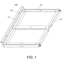
- the subrack storage frame 100 includes a first beam 10, two second beams 20, and a third beam 30.
- the first beam 10, the two second beams 20, and the third beam 30 surround to form a rectangular frame structure.
- the third beam 30 and the first beam 10 are oppositely disposed, and the two second beams 20 are oppositely disposed.
- the structures of the two second beams 20 are the same.
- the first beam 10 is formed by bending a sheet metal.
- the first beam 10 includes a limiting plate 11, a supporting plate 12, and a reinforcing plate 13, that is, the limiting plate 11, the supporting plate 12, and the reinforcing plate 13 is an integral structure formed by bending the sheet metal.
- the limiting plate 11 and the reinforcing plate 13 are respectively connected to two sides of the supporting plate 12.
- the limiting plate 11 is located above the supporting plate 12.
- the reinforcing plate 13 is located below the supporting plate 13.
- the supporting plate 12 is in the shape of a long plank.
- the supporting plate 12 is placed horizontally. Two sides of the supporting plate 12 in the length direction are respectively connected to the limiting plate 11 and the reinforcing plate 13.
- the lower end of the limiting plate 11 is connected to the supporting plate 12.
- the upper end of the reinforcing plate 13 is connected to the supporting plate 12.
- the limiting plate 11 and the reinforcing plate 13 are disposed parallel to each other.
- the reinforcing plate 13 is located on the front side of the supporting plate 12.
- the limiting plate 11 is located on the rear side of the supporting plate 12.
- the supporting plate 12 is configured to support a battery subrack.
- the limiting plate 11 is configured to abut the battery subrack along an insertion direction of the battery subrack, that is, the limiting plate 11 is disposed at the rear part of the insertion direction of the battery subrack and is used to limit an insertion position of the battery subrack.
- the battery subrack is placed on the subrack storage frame 100 and is limited by the limiting plate 11 to prevent the battery subrack from being suspended, that is, to prevent the battery subrack from being over-inserted.
- the supporting strength of the supporting plate 12 is strengthened through the reinforcing plate 13, thereby ensuring that the battery subrack is stably placed on the subrack storage frame 100.
- the supporting strength of the supporting plate 12 can be improved, thereby ensuring that the battery subrack is stably placed on the subrack storage frame 100.
- the battery subrack can be accurately installed in place, and the battery subrack is prevented from being suspended during the placement process, thereby further ensuring that the battery subrack is stably placed on the subrack storage frame 100.
- the surface of the limiting plate 11 facing the battery subrack is connected to a connector.
- the connector is located right above the supporting plate 12, and the connector is configured to be inserted into and match with the battery subrack.
- the connector is a plug 40.
- the rear side surface of the battery subrack is provided with a socket that matches with the plug 40.
- the battery subrack is positioned on the subrack storage frame 100, wherein the specific number of the plugs 40 may be set according to actual usage requirements.
- One, two, three, or more than three plugs 40 may be set.
- the limiting plate 11 is connected to two plugs 40 spaced apart to ensure the stability of the matching with the battery subrack.
- the plug 40 may be connected to the limiting plate 11 by welding, may also be connected to the limiting plate 11 through bolts, or may be fixedly connected to the limiting plate 11 through rivets, as long as any prior art for connecting the plug 40 to the limiting plate 11 is satisfied, the same should be included within the protection scope of the disclosure.
- the connector may also be a slot disposed on the limiting plate 11.
- the rear side surface of the battery subrack is provided with a plug that matches with the slot, so that the battery subrack may be positioned on the subrack storage frame 100 through the insertion and the matching of the plug and the slot.
- a distance D between the connector and the supporting plate 12 is less than the height of the battery subrack to prevent the setting position of the connector from being too high and unable to be inserted into and match with the battery subrack, thereby ensuring the stable positioning of the battery subrack on the subrack storage frame 100.
- the upper end of the limiting plate 11 is provided with a first hem 111 that can abut the battery subrack.
- the first hem 111 and the supporting plate 12 are disposed parallel to each other, the first hem 111 is located above the plug 40, the first hem 111 can not only protect the plug 40, but also increase the strength of the limiting plate 11, and can also adjust the position of the battery subrack on the subrack storage frame 100, that is, through adjusting the size of the first hem 111, the position of the battery subrack on the subrack storage frame 100 may be adjusted, and along the extension direction of the connector (the plug 40), the length of the first hem 111 is less than the length of the supporting plate 12, so that the first hem 111 neither affects the supporting effect of the first beam 10 on the battery subrack, nor affects the insertion and the matching between the plug 40 and the battery subrack.
- one end of the first hem 111 connected to the limiting plate 11 is a connection end, and the end of the first hem 111 opposite to the connection end is a free end.
- the free end of the first hem 111 is provided with a flange 112 extending toward the supporting plate 12.
- the connector (the plug 40) penetrates through the flange 112. Specifically, a through hole is formed on the flange 112 at a position corresponding to the plug 40, and the plug 40 passes through the through hole.
- the setting of the flange 112 can not only increase the contact area between the first hem 111 and the battery subrack to increase the strength of the first hem 111 against the battery subrack, that is, to use the flange 112 to buffer the force generated when the battery subrack is inserted, that is, to use the flange 112 to strengthen the first hem 111, thereby ensuring the service life of the first hem 111, but can also position the plug 40 to stably place the plug 40, so that the plug 40 can be smoothly inserted into and match with the battery subrack.
- the connector has a slot structure, and the battery subrack is provided with a plug, it is sufficient to correspondingly connect the slot and the through hole.
- a distance d between the connector (the plug 40) and the first hem 111 is less than or equal to 90% of the height of the battery subrack, and the distance d between the connector (the plug 40) and the first hem 111 is greater than or equal to 2% of the height of the battery subrack.
- the distance d between the connector (the plug 40) and the first hem 111 is 1 mm to 50 mm.
- Such a structure can not only prevent the distance d between the connector (the plug 40) and the first hem 111 from being too small, resulting in the impact force directly acting on the subrack to damage the subrack during the process of insertion and matching of the subrack and the connector, but can also prevent the distance d between the connector (the plug 40) and the first hem 111 from being too large, causing the flange 112 to be easily broken due to the impact force, such that the buffer performance cannot be achieved.
- the flange 112 and the limiting plate 11 are disposed parallel to each other.
- Such a structure not only facilitates the positioning of the through hole, but also facilitates the penetration of the plug 40 through the flange 112, while ensuring the maximum contact area between the flange 112 and the battery subrack.
- first gap 14 between the flange 112 and the supporting plate 12, that is, the projection area of the flange 112 on the limiting plate 11 is less than the area of the limiting plate 11.
- Such a structure can use the flange 112 to strengthen the first hem 111 without increasing the overall weight of the first beam 10.
- two ends of the limiting plate 11 are both provided with second hems 113.
- the first hem 111 and the flange 112 are both connected to the second hems 113, that is, the first hem 111, the flange 112, and the two second hems 113 surround to form a hollow structure with an open lower end, thereby further increasing the overall strength of the first beam 10.
- the second gap 15 can be inserted into and match with the second beam 20 to position the connection between the second beam 20 and the first beam 10, and increase the contact area between the second beam 20 and the first beam 10, thereby improving the connection strength between the second beam 20 and the first beam 10.
- the lower end of the reinforcing plate 13 is provided with a third hem 131.
- the third hem 131 increases the strength of the reinforcing plate 13 and further improves the overall strength of the first beam 10, wherein the third hem 131 may extend toward the limiting plate 11, and may also extend away from the limiting plate 11.
- the third hem 131 extends toward the limiting plate 11, and the third hem 131 is disposed substantially parallel to the supporting plate 12.
- the disclosure also provides the energy storage frame 200, which includes the subrack storage frame 100.
- the energy storage frame 200 includes a frame 201.
- the subrack storage frame is installed in the frame 201.
- the energy storage frame of the disclosure has the subrack storage frame, so the energy storage frame has the advantage of being able to stably place a large battery subrack.
- the energy storage frame further includes a column 2011.
- the frame 201 includes the column 2011.
- the subrack storage frame 100 further includes the second beam 20. One end of the first beam 10 is connected to the second beam 20, and the second beam 20 is connected to the column 2011, that is, the subrack storage frame 100 is connected to the column 2011 through the second beam 20.
- multiple subrack storage frames 100 disposed at intervals are connected on the column 2011 from top to bottom. Specifically, the inner space of the frame 201 is divided through the subrack storage frames 100 to form multiple accommodating cavities. One battery subrack may be inserted into each accommodating cavity. Each battery subrack is supported through one subrack storage frame 100.
- the disclosure also provides an energy storage battery cluster, which includes the energy storage frame 200 and at least one battery subrack 300.
- the battery subrack 300 is inserted into the energy storage frame 200, wherein the number of the battery subracks 300 may be adjusted according to actual usage requirements and the capacity of the energy storage frame 200.
- the energy storage battery cluster of the disclosure has the energy storage frame, so the energy storage battery cluster has the advantage of stable placement of a large battery subrack.
- the supporting strength of the supporting plate can be improved, thereby ensuring that the battery subrack is stably placed on the subrack storage frame.
- the battery subrack can be accurately installed in place, which prevents the battery subrack from being suspended during the placement process, thereby further ensuring that the battery subrack is stably placed on the subrack storage frame.
- the contact area between the first hem and the battery subrack is increased to increase the strength of the first hem against the battery subrack, that is, to strengthen the first hem, thereby ensuring the service life of the first hem.
- the flange is used to position the plug to stably place the plug, so that the plug can be smoothly inserted into and match with the battery subrack.
- the strength of the reinforcing plate is increased, thereby further improving the overall strength of the first beam.
- the energy storage frame of the disclosure has the subrack storage frame, so the energy storage frame has the advantage of being able to stably place a large battery subrack.
- the energy storage battery cluster of the disclosure has the energy storage frame, so the energy storage battery cluster has the advantage of stable placement of a large battery subrack.
Landscapes
- Chemical & Material Sciences (AREA)
- Chemical Kinetics & Catalysis (AREA)
- Electrochemistry (AREA)
- General Chemical & Material Sciences (AREA)
- Inorganic Chemistry (AREA)
- Battery Mounting, Suspending (AREA)
Abstract
Description
- The disclosure relates to the technical field of batteries, in particular to a subrack storage frame and an energy storage frame.
- The energy storage equipment is a new energy equipment that stores a battery subrack in the energy storage frame. Specifically, the battery subrack is placed on the subrack storage frame of the energy storage frame and is supported and positioned through a placement beam of the subrack storage frame. However, the currently used placement beam has a simple structure, has relatively low strength, and is not conducive to assembly, which is not conducive to the stable placement of a large battery subrack.
- The disclosure provides a subrack storage frame, which includes a first beam formed by bending a sheet metal. The first beam includes a limiting plate, a supporting plate, and a reinforcing plate. The limiting plate and the reinforcing plate are respectively connected to two sides of the supporting plate. The limiting plate is located above the supporting plate. The reinforcing plate is located below the supporting plate. The supporting plate is configured to support a battery subrack. The limiting plate is configured to abut the battery subrack along an insertion direction of the battery subrack.
- The disclosure provides an energy storage frame, which includes the subrack storage frame.
- The energy storage frame of the disclosure has the subrack storage frame, so the energy storage frame has the advantage of being able to stably place a large battery subrack.
- The disclosure provides an energy storage battery cluster, which includes the energy storage frame and at least one battery subrack, and the battery subrack is inserted into the energy storage frame.
- For a better understanding of the disclosure, reference may be made to exemplary embodiments shown in the following drawings. The components in the drawings are not necessarily to scale and related elements may be omitted, or in some instances proportions may have been exaggerated, so as to emphasize and clearly illustrate the features described herein. In addition, related elements or components can be variously arranged, as known in the art. Further, in the drawings, like reference numerals designate same or like parts throughout the several views.
-
FIG. 1 is a schematic diagram of a three-dimensional structure of a subrack storage frame of the disclosure. -
FIG. 2 is a schematic diagram of a three-dimensional structure of a first beam in the subrack storage frame shown inFIG. 1 . -
FIG. 3 is a schematic diagram of a cross-sectional three-dimensional structure of the first beam shown inFIG. 2 . -
FIG. 4 is a schematic diagram of a three-dimensional structure of an energy storage frame of the disclosure. -
FIG. 5 is a schematic diagram of a structure of an energy storage battery cluster of the disclosure. - The technical solutions in the exemplary embodiments of the disclosure will be described clearly and explicitly in conjunction with the drawings in the exemplary embodiments of the disclosure. The description proposed herein is just the exemplary embodiments for the purpose of illustrations only, not intended to limit the scope of the disclosure, so it should be understood that and various modifications and variations could be made thereto without departing from the scope of the disclosure.
- In the description of the present disclosure, unless otherwise specifically defined and limited, the terms "first", "second" and the like are only used for illustrative purposes and are not to be construed as expressing or implying a relative importance. The term "plurality" is two or more. The term "and/or" includes any and all combinations of one or more of the associated listed items.
- In particular, a reference to "the" object or "a" and "an" object is intended to denote also one of a possible plurality of such objects. Unless otherwise defined or described, the terms "connect", "fix" should be broadly interpreted, for example, the term "connect" can be "fixedly connect", "detachably connect", "integrally connect", "electrically connect" or "signal connect". The term "connect" also can be "directly connect" or "indirectly connect via a medium". For the persons skilled in the art, the specific meanings of the abovementioned terms in the present disclosure can be understood according to the specific situation.
- Further, in the description of the present disclosure, it should be understood that spatially relative terms, such as "above", "below" "inside", "outside" and the like, are described based on orientations illustrated in the figures, but are not intended to limit the exemplary embodiments of the present disclosure.
- In the context, it should also be understood that when an element or features is provided "outside" or "inside" of another element(s), it can be directly provided "outside" or "inside" of the other element, or be indirectly provided "outside" or "inside" of the another element(s) by an intermediate element.
- As shown in
FIG. 1 , the disclosure provides asubrack storage frame 100, which is used on anenergy storage frame 200. Thesubrack storage frame 100 includes afirst beam 10. Specifically, thesubrack storage frame 100 includes afirst beam 10, twosecond beams 20, and athird beam 30. Thefirst beam 10, the twosecond beams 20, and thethird beam 30 surround to form a rectangular frame structure. Thethird beam 30 and thefirst beam 10 are oppositely disposed, and the twosecond beams 20 are oppositely disposed. Preferably, the structures of the twosecond beams 20 are the same. - As shown in
FIG. 2 andFIG. 3 , thefirst beam 10 is formed by bending a sheet metal. Thefirst beam 10 includes alimiting plate 11, a supportingplate 12, and areinforcing plate 13, that is, thelimiting plate 11, the supportingplate 12, and thereinforcing plate 13 is an integral structure formed by bending the sheet metal. Thelimiting plate 11 and thereinforcing plate 13 are respectively connected to two sides of the supportingplate 12. Thelimiting plate 11 is located above the supportingplate 12. The reinforcingplate 13 is located below the supportingplate 13. Specifically, the supportingplate 12 is in the shape of a long plank. The supportingplate 12 is placed horizontally. Two sides of the supportingplate 12 in the length direction are respectively connected to thelimiting plate 11 and thereinforcing plate 13. The lower end of thelimiting plate 11 is connected to the supportingplate 12. The upper end of thereinforcing plate 13 is connected to the supportingplate 12. Preferably, thelimiting plate 11 and thereinforcing plate 13 are disposed parallel to each other. The reinforcingplate 13 is located on the front side of the supportingplate 12. Thelimiting plate 11 is located on the rear side of the supportingplate 12. The supportingplate 12 is configured to support a battery subrack. Thelimiting plate 11 is configured to abut the battery subrack along an insertion direction of the battery subrack, that is, thelimiting plate 11 is disposed at the rear part of the insertion direction of the battery subrack and is used to limit an insertion position of the battery subrack. Specifically, during use, the battery subrack is placed on thesubrack storage frame 100 and is limited by thelimiting plate 11 to prevent the battery subrack from being suspended, that is, to prevent the battery subrack from being over-inserted. At the same time, the supporting strength of the supportingplate 12 is strengthened through the reinforcingplate 13, thereby ensuring that the battery subrack is stably placed on thesubrack storage frame 100. - In the
subrack storage frame 100 of the disclosure, through setting the reinforcingplate 13, the supporting strength of the supportingplate 12 can be improved, thereby ensuring that the battery subrack is stably placed on thesubrack storage frame 100. Through setting thelimiting plate 11, the battery subrack can be accurately installed in place, and the battery subrack is prevented from being suspended during the placement process, thereby further ensuring that the battery subrack is stably placed on thesubrack storage frame 100. - Further, as shown in
FIG. 2 andFIG. 3 , the surface of the limitingplate 11 facing the battery subrack is connected to a connector. Specifically, the connector is located right above the supportingplate 12, and the connector is configured to be inserted into and match with the battery subrack. Specifically, the connector is aplug 40. The rear side surface of the battery subrack is provided with a socket that matches with theplug 40. Through the insertion and the matching of theplug 40 and the socket, the battery subrack is positioned on thesubrack storage frame 100, wherein the specific number of theplugs 40 may be set according to actual usage requirements. One, two, three, or more than threeplugs 40 may be set. Preferably, the limitingplate 11 is connected to twoplugs 40 spaced apart to ensure the stability of the matching with the battery subrack. - The
plug 40 may be connected to the limitingplate 11 by welding, may also be connected to the limitingplate 11 through bolts, or may be fixedly connected to the limitingplate 11 through rivets, as long as any prior art for connecting theplug 40 to the limitingplate 11 is satisfied, the same should be included within the protection scope of the disclosure. - Of course, the connector may also be a slot disposed on the limiting
plate 11. The rear side surface of the battery subrack is provided with a plug that matches with the slot, so that the battery subrack may be positioned on thesubrack storage frame 100 through the insertion and the matching of the plug and the slot. - Further, a distance D between the connector and the supporting
plate 12 is less than the height of the battery subrack to prevent the setting position of the connector from being too high and unable to be inserted into and match with the battery subrack, thereby ensuring the stable positioning of the battery subrack on thesubrack storage frame 100. - Further, as shown in
FIG. 2 andFIG. 3 , the upper end of the limitingplate 11 is provided with afirst hem 111 that can abut the battery subrack. Specifically, thefirst hem 111 and the supportingplate 12 are disposed parallel to each other, thefirst hem 111 is located above theplug 40, thefirst hem 111 can not only protect theplug 40, but also increase the strength of the limitingplate 11, and can also adjust the position of the battery subrack on thesubrack storage frame 100, that is, through adjusting the size of thefirst hem 111, the position of the battery subrack on thesubrack storage frame 100 may be adjusted, and along the extension direction of the connector (the plug 40), the length of thefirst hem 111 is less than the length of the supportingplate 12, so that thefirst hem 111 neither affects the supporting effect of thefirst beam 10 on the battery subrack, nor affects the insertion and the matching between theplug 40 and the battery subrack. - Further, as shown in
FIG. 2 andFIG. 3 , one end of thefirst hem 111 connected to the limitingplate 11 is a connection end, and the end of thefirst hem 111 opposite to the connection end is a free end. The free end of thefirst hem 111 is provided with aflange 112 extending toward the supportingplate 12. The connector (the plug 40) penetrates through theflange 112. Specifically, a through hole is formed on theflange 112 at a position corresponding to theplug 40, and theplug 40 passes through the through hole. The setting of theflange 112 can not only increase the contact area between thefirst hem 111 and the battery subrack to increase the strength of thefirst hem 111 against the battery subrack, that is, to use theflange 112 to buffer the force generated when the battery subrack is inserted, that is, to use theflange 112 to strengthen thefirst hem 111, thereby ensuring the service life of thefirst hem 111, but can also position theplug 40 to stably place theplug 40, so that theplug 40 can be smoothly inserted into and match with the battery subrack. - It should be noted that when the connector has a slot structure, and the battery subrack is provided with a plug, it is sufficient to correspondingly connect the slot and the through hole.
- Further, a distance d between the connector (the plug 40) and the
first hem 111 is less than or equal to 90% of the height of the battery subrack, and the distance d between the connector (the plug 40) and thefirst hem 111 is greater than or equal to 2% of the height of the battery subrack. Exemplarily, the distance d between the connector (the plug 40) and thefirst hem 111 is 1 mm to 50 mm. Such a structure can not only prevent the distance d between the connector (the plug 40) and thefirst hem 111 from being too small, resulting in the impact force directly acting on the subrack to damage the subrack during the process of insertion and matching of the subrack and the connector, but can also prevent the distance d between the connector (the plug 40) and thefirst hem 111 from being too large, causing theflange 112 to be easily broken due to the impact force, such that the buffer performance cannot be achieved. - Further, as shown in
FIG. 2 andFIG. 3 , theflange 112 and the limitingplate 11 are disposed parallel to each other. Such a structure not only facilitates the positioning of the through hole, but also facilitates the penetration of theplug 40 through theflange 112, while ensuring the maximum contact area between theflange 112 and the battery subrack. - Further, as shown in
FIG. 2 andFIG. 3 , there is afirst gap 14 between theflange 112 and the supportingplate 12, that is, the projection area of theflange 112 on the limitingplate 11 is less than the area of the limitingplate 11. Such a structure can use theflange 112 to strengthen thefirst hem 111 without increasing the overall weight of thefirst beam 10. - Further, as shown in
FIG. 2 andFIG. 3 , two ends of the limitingplate 11 are both provided withsecond hems 113. Thefirst hem 111 and theflange 112 are both connected to thesecond hems 113, that is, thefirst hem 111, theflange 112, and the twosecond hems 113 surround to form a hollow structure with an open lower end, thereby further increasing the overall strength of thefirst beam 10. - Further, as shown in
FIG. 2 andFIG. 3 , there is asecond gap 15 between thesecond hem 113 and the supportingplate 12, that is, thesecond hem 113 is not in contact with the supportingplate 12. Thesecond gap 15 can be inserted into and match with thesecond beam 20 to position the connection between thesecond beam 20 and thefirst beam 10, and increase the contact area between thesecond beam 20 and thefirst beam 10, thereby improving the connection strength between thesecond beam 20 and thefirst beam 10. - Further, as shown in
FIG. 2 andFIG. 3 , the lower end of the reinforcingplate 13 is provided with athird hem 131. Thethird hem 131 increases the strength of the reinforcingplate 13 and further improves the overall strength of thefirst beam 10, wherein thethird hem 131 may extend toward the limitingplate 11, and may also extend away from the limitingplate 11. In order to reduce the overall size of thefirst beam 10, and to facilitate placement, preferably, thethird hem 131 extends toward the limitingplate 11, and thethird hem 131 is disposed substantially parallel to the supportingplate 12. - As shown in
FIG. 4 , the disclosure also provides theenergy storage frame 200, which includes thesubrack storage frame 100. Specifically, theenergy storage frame 200 includes aframe 201. The subrack storage frame is installed in theframe 201. - The energy storage frame of the disclosure has the subrack storage frame, so the energy storage frame has the advantage of being able to stably place a large battery subrack.
- Further, as shown in
FIG. 4 , the energy storage frame further includes acolumn 2011. Specifically, theframe 201 includes thecolumn 2011. Thesubrack storage frame 100 further includes thesecond beam 20. One end of thefirst beam 10 is connected to thesecond beam 20, and thesecond beam 20 is connected to thecolumn 2011, that is, thesubrack storage frame 100 is connected to thecolumn 2011 through thesecond beam 20. - Further, multiple subrack storage frames 100 disposed at intervals are connected on the
column 2011 from top to bottom. Specifically, the inner space of theframe 201 is divided through the subrack storage frames 100 to form multiple accommodating cavities. One battery subrack may be inserted into each accommodating cavity. Each battery subrack is supported through onesubrack storage frame 100. - As shown in
FIG. 5 , the disclosure also provides an energy storage battery cluster, which includes theenergy storage frame 200 and at least onebattery subrack 300. Thebattery subrack 300 is inserted into theenergy storage frame 200, wherein the number of thebattery subracks 300 may be adjusted according to actual usage requirements and the capacity of theenergy storage frame 200. - The energy storage battery cluster of the disclosure has the energy storage frame, so the energy storage battery cluster has the advantage of stable placement of a large battery subrack.
- In summary, in the subrack storage frame of the disclosure, through setting the reinforcing plate, the supporting strength of the supporting plate can be improved, thereby ensuring that the battery subrack is stably placed on the subrack storage frame. Through setting the limiting plate, the battery subrack can be accurately installed in place, which prevents the battery subrack from being suspended during the placement process, thereby further ensuring that the battery subrack is stably placed on the subrack storage frame.
- In the subrack storage frame of the disclosure, through setting the first hem and setting the flange on the first hem, the contact area between the first hem and the battery subrack is increased to increase the strength of the first hem against the battery subrack, that is, to strengthen the first hem, thereby ensuring the service life of the first hem. Also, the flange is used to position the plug to stably place the plug, so that the plug can be smoothly inserted into and match with the battery subrack.
- In the subrack storage frame of the disclosure, through setting the third hem at the lower end of the reinforcing plate, the strength of the reinforcing plate is increased, thereby further improving the overall strength of the first beam.
- The energy storage frame of the disclosure has the subrack storage frame, so the energy storage frame has the advantage of being able to stably place a large battery subrack.
- The energy storage battery cluster of the disclosure has the energy storage frame, so the energy storage battery cluster has the advantage of stable placement of a large battery subrack.
- Other embodiments of the disclosure will be apparent to those skilled in the art from consideration of the specification and practice of the disclosure disclosed herein. The disclosure is intended to cover any variations, uses or adaptations of the disclosure. These variations, uses, or adaptations follow the general principles of the disclosure and include common general knowledge or conventional technical means in the art that are not disclosed in the present disclosure.
Claims (15)
- A subrack storage frame (100), comprising a first beam (10) formed by bending a sheet metal, wherein the first beam (10) comprises a limiting plate (11), a supporting plate (12), and a reinforcing plate (13), the limiting plate (11) and the reinforcing plate (13) are respectively connected to two sides of the supporting plate (12), the limiting plate (11) is located above the supporting plate (12), the reinforcing plate (13) is located below the supporting plate (12), the supporting plate (12) is configured to support a battery subrack, and the limiting plate (11) is configured to abut the battery subrack along an insertion direction of the battery subrack.
- The subrack storage frame (100) according to claim 1, wherein:
a surface of the limiting plate (11) facing the battery subrack is connected to a connector (40), and the connector (40) is configured to be inserted into and match with the battery subrack. - The subrack storage frame (100) according to claim 2, wherein:
a distance (D) between the connector (40) and the supporting plate (12) is less than a height of the battery subrack. - The subrack storage frame (100) according to claim 2, wherein:
an upper end of the limiting plate (11) is provided with a first hem (111) abutting the battery subrack, and a length of the first hem (111) is less than a length of the supporting plate (12) along an extension direction of the connector (40). - The subrack storage frame (100) according to claim 4, wherein:
a free end of the first hem (111) is provided with a flange (112) extending toward the supporting plate (12), and the connector (40) penetrates through the flange (112). - The subrack storage frame (100) according to claim 5, wherein:
a distance (d) between the connector (40) and the first hem (111) is less than or equal to 90% of a height of the battery subrack. - The subrack storage frame (100) according to claim 6, wherein:
the distance (d) between the connector (40) and the first hem (111) is greater than or equal to 2% of the height of the battery subrack. - The subrack storage frame (100) according to claim 5, wherein:
the flange (112) and the limiting plate (11) are disposed parallel to each other. - The subrack storage frame (100) according to claim 5, wherein:
there is a first gap (14) between the flange (112) and the supporting plate (12). - The subrack storage frame (100) according to claim 5, wherein:
two ends of the limiting plate (11) are both provided with second hems (113), and the first hem (111) and the flange (112) are both connected to the second hem (113). - The subrack storage frame (100) according to claim 10, wherein:
there is a second gap (15) between the second hem (113) and the supporting plate (12). - The subrack storage frame (100) according to any one of claims 1-11, wherein:
a lower end of the reinforcing plate (13) is provided with a third hem (131). - An energy storage frame (200), comprising the subrack storage frame (100) according to any one of claims 1-12.
- The energy storage frame (200) according to claim 13, wherein the energy storage frame (200) further comprises a column (2011), and a plurality of the subrack storage frames (100) disposed at intervals are connected on the column (2011) from top to bottom.
- An energy storage battery cluster, comprising the energy storage frame (200) according to claim 13 or 14 and at least one battery subrack, wherein the battery subrack is inserted into the energy storage frame (200).
Applications Claiming Priority (1)
| Application Number | Priority Date | Filing Date | Title |
|---|---|---|---|
| CN202210298984.0A CN114552101B (en) | 2022-03-25 | Packing rack, energy storage rack and battery cluster |
Publications (2)
| Publication Number | Publication Date |
|---|---|
| EP4345927A2 true EP4345927A2 (en) | 2024-04-03 |
| EP4345927A3 EP4345927A3 (en) | 2024-06-12 |
Family
ID=81666234
Family Applications (1)
| Application Number | Title | Priority Date | Filing Date |
|---|---|---|---|
| EP22185928.3A Withdrawn EP4345927A3 (en) | 2022-03-25 | 2022-07-20 | Battery shelf, energy storage frame, and energy storage battery cluster |
Country Status (2)
| Country | Link |
|---|---|
| US (1) | US20230307765A1 (en) |
| EP (1) | EP4345927A3 (en) |
Family Cites Families (76)
| Publication number | Priority date | Publication date | Assignee | Title |
|---|---|---|---|---|
| USRE24535E (en) * | 1958-09-16 | - shelving unit | ||
| US3042221A (en) * | 1960-08-19 | 1962-07-03 | Acme Steel Co | Pallet rack |
| US3278043A (en) * | 1965-02-16 | 1966-10-11 | Palmer Shile Co | Storage rack |
| US3349924A (en) * | 1965-12-06 | 1967-10-31 | American Handling Equipment Co | Storage device for articles and method |
| US3463325A (en) * | 1967-06-22 | 1969-08-26 | Interlake Steel Corp | Pallet rack beam retainer |
| US3584904A (en) * | 1969-03-13 | 1971-06-15 | Flangeklamp Corp | Locking connection for supporting grid systems |
| US3695456A (en) * | 1970-07-17 | 1972-10-03 | Bernard Gloekler | Pallet rack |
| IT1012117B (en) * | 1973-01-12 | 1977-03-10 | Mavil | DEVICE FOR ASSEMBLY OF UPRIGHTS AND SIDES FOR REMOVABLE SHELVING |
| US4101233A (en) * | 1977-03-25 | 1978-07-18 | Interlake, Inc. | Panel mounting clip for storage rack |
| US4078664A (en) * | 1977-03-25 | 1978-03-14 | Interlake, Inc. | Cross bar |
| JPS5577306A (en) * | 1978-12-04 | 1980-06-11 | Tokyo Shibaura Electric Co | Enclosed switchboard |
| US4285436A (en) * | 1978-12-26 | 1981-08-25 | Speedshelf International, Inc. | Integral locking tab for storage racks |
| US4270661A (en) * | 1979-05-03 | 1981-06-02 | Parsteel Products & Services Company, Inc. | Battery storage rack |
| US4383614A (en) * | 1980-09-22 | 1983-05-17 | Nestier Corporation | Clip for releasably locking rails to supports |
| IT1208160B (en) * | 1982-02-05 | 1989-06-06 | Passoni Paolo E Figli S R L | MODULAR MODULAR BENCH STRUCTURE FOR SUPPORTING ACCUMULATORS PARTICULARLY. |
| SE437647B (en) * | 1982-11-22 | 1985-03-11 | Electrolux Const Ab | DEVICE FOR STORAGE, EXV PALLET |
| US4665838A (en) * | 1985-09-26 | 1987-05-19 | Minshall Aubrey W | Shelving unit |
| FR2637155A1 (en) * | 1988-09-29 | 1990-03-30 | Merlin Gerin | MODULAR CABINET FOR ELECTRICAL BATTERIES |
| DE69304617T2 (en) * | 1992-06-15 | 1997-03-27 | Gnb Ind Battery Co | Modular housing structure for batteries |
| US5749481A (en) * | 1994-01-03 | 1998-05-12 | Miller; Myron W. | Storage rack and structural beam therefor |
| US5437939A (en) * | 1994-01-06 | 1995-08-01 | Gnb Industrial Battery Company | Sealed lead-acid battery tray assemblies and motive power vehicles using such battery tray assemblies |
| US5890606A (en) * | 1997-07-10 | 1999-04-06 | Lucent Technologies Inc. | Battery rack having low resistance compartment dividers and methods of operation and manufacture thereof |
| IT1298112B1 (en) * | 1998-01-13 | 1999-12-20 | Passoni Paolo E Figli S R L | MODULAR BENCH THAT CAN BE MODULATED WITH ANTI-SEISMIC RETAINING MEANS, ESPECIALLY FOR ACCUMULATORS AND SIMILAR |
| US6105798A (en) * | 1998-11-06 | 2000-08-22 | Interlake Material Handling, Inc. | Rack with special mounting arrangement |
| WO2000030190A1 (en) * | 1998-11-17 | 2000-05-25 | C & D Technologies, Inc. | Selectable capacity fixed footprint lead-acid battery racking system with horizontal plates |
| US6308728B1 (en) * | 1999-10-27 | 2001-10-30 | Douglas Frazier | Spill containment system and method |
| US6482541B1 (en) * | 1999-11-03 | 2002-11-19 | Enersys Inc. | Battery sleeve frame |
| US6310783B1 (en) * | 2000-03-29 | 2001-10-30 | Powerware Corporation | Modular method and apparatus for building an uninterruptible power system (UPS) |
| US6451475B1 (en) * | 2000-07-05 | 2002-09-17 | East Penn Manufacturing Company, Inc. | Front access interlocking modular cell tray assembly |
| AU2001294747B2 (en) * | 2000-09-27 | 2006-10-12 | Exide Technologies | Seismic rated battery racking system |
| US6520357B1 (en) * | 2001-01-10 | 2003-02-18 | Interlake Material Handling, Inc. | Rack with members attached by clips |
| US6719150B2 (en) * | 2001-05-30 | 2004-04-13 | Kim Manufacturing Company | Battery rack and system |
| US20040079714A1 (en) * | 2001-11-20 | 2004-04-29 | Marraffa Andrew | Battery rack |
| US7740142B2 (en) * | 2001-11-20 | 2010-06-22 | Concorde Battery Corporation | Battery construction for mounting a shelved rack |
| US6595379B1 (en) * | 2002-02-01 | 2003-07-22 | United Steel Enterprises, Inc. | Lock for preventing inadvertent removal of a first frame component of an adjustable storage system from a second frame component of the adjustable storage system and the adjustable storage system |
| US6936372B1 (en) * | 2002-08-15 | 2005-08-30 | Tyco Electronics Power Systems, Inc. | Environmental control system for use with a battery cabinet and method of operating a fan therein |
| US7323271B2 (en) * | 2003-08-27 | 2008-01-29 | Kim Manufacturing Company | Front access battery tray apparatus and system |
| US7548429B2 (en) * | 2004-06-18 | 2009-06-16 | Douglas Battery Manufacturing Company | Battery storage system |
| US7575828B2 (en) * | 2004-07-23 | 2009-08-18 | Kim Manufacturing Co. | Modular rack assemblies for sealed lead acid batteries |
| US8100271B2 (en) * | 2006-02-02 | 2012-01-24 | C & C Power | Tiered battery cabinet |
| US7838142B2 (en) * | 2006-02-09 | 2010-11-23 | Scheucher Karl F | Scalable intelligent power supply system and method |
| US8721010B2 (en) * | 2006-05-05 | 2014-05-13 | C&C Power, Inc | Equipment cabinet |
| US20080272676A1 (en) * | 2007-05-04 | 2008-11-06 | Brian Eustace | Boltless cabinet assembly |
| US8172098B2 (en) * | 2008-05-06 | 2012-05-08 | Rapid Rack Industries, Inc. | Modular rack assembly |
| US9375102B2 (en) * | 2010-07-02 | 2016-06-28 | Edsal Manufacturing Company, Inc. | Portion of shelf and support for shelving unit |
| US8443992B2 (en) * | 2010-09-21 | 2013-05-21 | Whalen Furniture Manufacturing, Inc. a California corporation | Industrial frame rack support assembly |
| JPWO2012102383A1 (en) * | 2011-01-28 | 2014-07-03 | 三洋電機株式会社 | Power storage system |
| US20140017528A1 (en) * | 2011-03-31 | 2014-01-16 | Yuji Uehara | Rack-mount power supply device and battery pack including detachable connector |
| KR101255243B1 (en) * | 2011-04-15 | 2013-04-16 | 삼성에스디아이 주식회사 | Rack housing assembly and energy storage apparatus having the same |
| KR101278506B1 (en) * | 2011-04-25 | 2013-07-02 | 주식회사 엘지화학 | Rack system of battery module for energy storage |
| US8900737B2 (en) * | 2011-09-08 | 2014-12-02 | Samsung Sdi Co., Ltd. | Energy storage system |
| JP5145452B1 (en) * | 2011-09-16 | 2013-02-20 | 日本航空電子工業株式会社 | Power storage device |
| US8695816B2 (en) * | 2011-10-25 | 2014-04-15 | Edsal Manufacturing Co., Inc. | Dual function shelf unit |
| US9027767B2 (en) * | 2012-10-29 | 2015-05-12 | Whirlpool Corporation | Rack shelving unit |
| WO2014078941A1 (en) * | 2012-11-22 | 2014-05-30 | Ecamion Inc. | Community energy storage system with battery bank deactivation |
| DE102013110361A1 (en) * | 2013-09-19 | 2015-03-19 | Nedcon Magazijninrichting B.V. | goods storage |
| US9386855B2 (en) * | 2013-09-27 | 2016-07-12 | Pro-Mart Industries, Inc. | Storage rack and cross-bar support |
| US20150313357A1 (en) * | 2014-01-17 | 2015-11-05 | Silverack, Llc | Shelving Units And Accessories |
| US9215926B1 (en) * | 2014-06-14 | 2015-12-22 | Lf Centennial Limited | Storage rack with improved tie support |
| US9215931B1 (en) * | 2014-06-14 | 2015-12-22 | Lt Centennial Limited | Storage rack with improved tie support |
| KR102284484B1 (en) * | 2014-08-25 | 2021-08-02 | 삼성에스디아이 주식회사 | Rack housing assembly and energy stroge apparatus having the same |
| CN107429720B (en) * | 2015-05-08 | 2019-03-08 | 三菱电机株式会社 | Frame assembly and box |
| KR102490868B1 (en) * | 2015-11-09 | 2023-01-20 | 삼성에스디아이 주식회사 | Battery rack |
| KR102501081B1 (en) * | 2016-01-26 | 2023-02-17 | 삼성에스디아이 주식회사 | Battery assembly |
| US9661921B1 (en) * | 2016-02-19 | 2017-05-30 | Frank Tsai | Multiple shelving apparatus |
| US20170280875A1 (en) * | 2016-03-31 | 2017-10-05 | Whirlpool Corporation | Weldless support beam for rack shelving |
| US10193112B2 (en) * | 2016-04-08 | 2019-01-29 | Lockheed Martin Energy, Llc | Modular energy storage component enclosure |
| KR102079780B1 (en) * | 2016-09-02 | 2020-02-20 | 주식회사 엘지화학 | Strap for Battery Module, Battery Module including the same and Jig for compressing Strap |
| CA3041762A1 (en) * | 2016-12-16 | 2018-06-21 | Peak Innovations Inc. | Shelving system |
| US10299594B2 (en) * | 2017-03-28 | 2019-05-28 | Edsal Manufacturing Company, Inc. | Shelving unit with capacity increasing tie members |
| US10644275B2 (en) * | 2017-10-13 | 2020-05-05 | Toshiba International Corporation | Front access battery tray and battery storage system |
| US11876251B2 (en) * | 2018-06-22 | 2024-01-16 | Gs Yuasa International Ltd. | Energy storage apparatus |
| JP7451094B2 (en) * | 2019-05-09 | 2024-03-18 | 株式会社東芝 | storage battery device |
| EP4050630B1 (en) * | 2019-10-23 | 2025-10-01 | GS Yuasa International Ltd. | Electrical storage device |
| CA3192968A1 (en) * | 2020-09-16 | 2022-03-24 | Jared W. Hanlon | Utility rack |
| CN214542385U (en) * | 2021-04-08 | 2021-10-29 | 阳光储能技术有限公司 | an energy storage device |
-
2022
- 2022-07-19 US US17/868,752 patent/US20230307765A1/en not_active Abandoned
- 2022-07-20 EP EP22185928.3A patent/EP4345927A3/en not_active Withdrawn
Also Published As
| Publication number | Publication date |
|---|---|
| CN114552101A (en) | 2022-05-27 |
| EP4345927A3 (en) | 2024-06-12 |
| US20230307765A1 (en) | 2023-09-28 |
Similar Documents
| Publication | Publication Date | Title |
|---|---|---|
| US11606060B2 (en) | Locking device, photovoltaic module mounting structure, and photovoltaic system | |
| US20220285779A1 (en) | Battery rack having fixing frame and energy storage system | |
| EP4632906A1 (en) | Energy storage container | |
| CN115715436A (en) | Battery holder, energy storage device, and power generation system | |
| EP4345983A1 (en) | Liquid-cooled battery module and battery pack | |
| EP4345927A2 (en) | Battery shelf, energy storage frame, and energy storage battery cluster | |
| EP4345926A2 (en) | Battery shelf, energy storage frame, and energy storage battery cluster | |
| US20230307753A1 (en) | Energy storage frame and energy storage battery cluster | |
| CN220233378U (en) | Battery device | |
| EP4250447A2 (en) | Storage rack, energy storage frame, and energy storage battery cluster | |
| CN115863896A (en) | Battery support and energy storage device | |
| CN220086254U (en) | Battery box and battery device | |
| CN219717152U (en) | Battery pack, electric automobile and electric equipment | |
| CN114552101B (en) | Packing rack, energy storage rack and battery cluster | |
| CN210516756U (en) | Battery pack structure of double-layer module | |
| CN214204421U (en) | Block terminal convenient to installation | |
| KR20240051017A (en) | Battery rack and energy storage system comprising the same | |
| CN217035859U (en) | Subrack rack, energy storage rack and battery cluster | |
| CN217361814U (en) | Series-parallel connection fixing plate of soft package lithium battery | |
| CN223200317U (en) | Rack and unmanned aerial vehicle | |
| CN213847366U (en) | Military anti-drying plug-in box | |
| CN216467759U (en) | Lightning arrester mounting bracket, bogie and suspension type rail vehicle | |
| CN212786140U (en) | Switch board with crashproof | |
| CN220106632U (en) | Energy storage battery pack | |
| CN219740013U (en) | Single-door energy storage electric cabinet box |
Legal Events
| Date | Code | Title | Description |
|---|---|---|---|
| PUAI | Public reference made under article 153(3) epc to a published international application that has entered the european phase |
Free format text: ORIGINAL CODE: 0009012 |
|
| STAA | Information on the status of an ep patent application or granted ep patent |
Free format text: STATUS: REQUEST FOR EXAMINATION WAS MADE |
|
| 17P | Request for examination filed |
Effective date: 20220720 |
|
| AK | Designated contracting states |
Kind code of ref document: A2 Designated state(s): AL AT BE BG CH CY CZ DE DK EE ES FI FR GB GR HR HU IE IS IT LI LT LU LV MC MK MT NL NO PL PT RO RS SE SI SK SM TR |
|
| REG | Reference to a national code |
Ref country code: DE Ref legal event code: R079 Free format text: PREVIOUS MAIN CLASS: H01M0004000000 Ipc: H01M0050204000 |
|
| PUAL | Search report despatched |
Free format text: ORIGINAL CODE: 0009013 |
|
| AK | Designated contracting states |
Kind code of ref document: A3 Designated state(s): AL AT BE BG CH CY CZ DE DK EE ES FI FR GB GR HR HU IE IS IT LI LT LU LV MC MK MT NL NO PL PT RO RS SE SI SK SM TR |
|
| RIC1 | Information provided on ipc code assigned before grant |
Ipc: H01M 50/224 20210101ALI20240506BHEP Ipc: H01M 50/204 20210101AFI20240506BHEP |
|
| STAA | Information on the status of an ep patent application or granted ep patent |
Free format text: STATUS: THE APPLICATION IS DEEMED TO BE WITHDRAWN |
|
| 18D | Application deemed to be withdrawn |
Effective date: 20241213 |