EP4345518A1 - Apparatus and method for low latency free-space optical communications - Google Patents
Apparatus and method for low latency free-space optical communications Download PDFInfo
- Publication number
- EP4345518A1 EP4345518A1 EP23198381.8A EP23198381A EP4345518A1 EP 4345518 A1 EP4345518 A1 EP 4345518A1 EP 23198381 A EP23198381 A EP 23198381A EP 4345518 A1 EP4345518 A1 EP 4345518A1
- Authority
- EP
- European Patent Office
- Prior art keywords
- optical
- core
- cores
- fibers
- channel
- Prior art date
- Legal status (The legal status is an assumption and is not a legal conclusion. Google has not performed a legal analysis and makes no representation as to the accuracy of the status listed.)
- Granted
Links
Images







Classifications
-
- G—PHYSICS
- G02—OPTICS
- G02B—OPTICAL ELEMENTS, SYSTEMS OR APPARATUS
- G02B6/00—Light guides; Structural details of arrangements comprising light guides and other optical elements, e.g. couplings
- G02B6/24—Coupling light guides
- G02B6/26—Optical coupling means
- G02B6/262—Optical details of coupling light into, or out of, or between fibre ends, e.g. special fibre end shapes or associated optical elements
-
- G—PHYSICS
- G02—OPTICS
- G02B—OPTICAL ELEMENTS, SYSTEMS OR APPARATUS
- G02B6/00—Light guides; Structural details of arrangements comprising light guides and other optical elements, e.g. couplings
- G02B6/02—Optical fibres with cladding with or without a coating
- G02B6/02042—Multicore optical fibres
-
- G—PHYSICS
- G02—OPTICS
- G02B—OPTICAL ELEMENTS, SYSTEMS OR APPARATUS
- G02B6/00—Light guides; Structural details of arrangements comprising light guides and other optical elements, e.g. couplings
- G02B6/24—Coupling light guides
- G02B6/26—Optical coupling means
- G02B6/32—Optical coupling means having lens focusing means positioned between opposed fibre ends
-
- H—ELECTRICITY
- H04—ELECTRIC COMMUNICATION TECHNIQUE
- H04B—TRANSMISSION
- H04B10/00—Transmission systems employing electromagnetic waves other than radio-waves, e.g. infrared, visible or ultraviolet light, or employing corpuscular radiation, e.g. quantum communication
- H04B10/11—Arrangements specific to free-space transmission, i.e. transmission through air or vacuum
-
- H—ELECTRICITY
- H04—ELECTRIC COMMUNICATION TECHNIQUE
- H04B—TRANSMISSION
- H04B10/00—Transmission systems employing electromagnetic waves other than radio-waves, e.g. infrared, visible or ultraviolet light, or employing corpuscular radiation, e.g. quantum communication
- H04B10/11—Arrangements specific to free-space transmission, i.e. transmission through air or vacuum
- H04B10/112—Line-of-sight transmission over an extended range
- H04B10/1123—Bidirectional transmission
- H04B10/1127—Bidirectional transmission using two distinct parallel optical paths
-
- H—ELECTRICITY
- H04—ELECTRIC COMMUNICATION TECHNIQUE
- H04B—TRANSMISSION
- H04B10/00—Transmission systems employing electromagnetic waves other than radio-waves, e.g. infrared, visible or ultraviolet light, or employing corpuscular radiation, e.g. quantum communication
- H04B10/25—Arrangements specific to fibre transmission
- H04B10/2581—Multimode transmission
Definitions
- the present invention generally relates to the field of high-speed optical fiber communication channels and, more specifically, to a low latency optical channel.
- the disclosed apparatus and method enables optical communication signals to propagate through free-space, thereby traveling at the speed of light in air minimizing propagation time.
- the disclosed apparatus and method provides low latency optical signal paths for a multiplicity of discrete channels equalizing the propagation delay between adjacent channels.
- Free-space optical communications in various forms has been used for thousands of years.
- the ancient Greeks used a coded alphabetic system of signals to communicate utilizing torches.
- Alexander Graham Bell created the photophone, which he considered his most important invention and was the world's first wireless telephone. Bell demonstrated voice communications over free-space optics between two building some 213 meters apart.
- red filtered light signals provided undetected communications at night.
- free-space optical communications is widely used in commercial, military, and space applications.
- optical fiber communications Today, large data centers utilize optical fiber communications to achieve the high-speed and long channel reaches required for the switch-to-switch and switch-to-server interconnections.
- traders demand minimum transaction delay and guaranteed equivalent optical signal delay compared to other traders.
- these high-speed transactions propagate over standard single-mode and/or multimode optical fibers.
- optical fiber cable assemblies are custom manufactured where the discrete fiber lengths within said cable are precisely measured using optical time domain reflectometers (OTDRs) to ensure the optical channel delays are equivalent.
- OTDRs optical time domain reflectometers
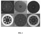
- hollow core fibers where the core is a channel of air surrounded by an array of hollow tubes which form reflective micro-structures cladding, to confine the optical beam, Fig. 1 .
- these fiber types are extremely difficult to manufacture in high volume and hence, are extremely expensive, i.e., hundreds to thousands of dollars per meter.
- Hollow core fibers also exhibit high attenuation (insertion loss) due to the coupling of the light's electromagnetic fields with the surrounding fiber core structure.
- these fiber types due to the highly controlled spacing between fiber core elements, these fiber types and are very fragile and susceptible of degradation in performance as a result of bending. Consequently, hollow core fibers must have a robust cable design, and have a large bend radius not to deform or damage the core structure.
- the optical signal propagates near that of the speed of light in vacuum so that channels of said communication signals undergo minimum delay, and traders can be guaranteed equivalent optical channel paths.
- the speed of an optical signal is determined by the refractive index of the medium in which it propagates, where the refractive index is effectively the optical dielectric constant of the medium.
- the refractive index of glass, as used in optical fibers is about 1.467.
- the speed of light in optical fiber is 204,357,504 m/s, or 68% of the maximum speed of light in vacuum.
- the time of flight in vacuum is 250 ns.
- the time of flight for a 75 m channel is 367 ns, introducing a delay of 117 ns, or 0.117 ⁇ s. For high-speed trading, this is not acceptable.
- the authors of this disclosure measured the refractive index, and hence the optical signal delay in a commercially available hollow core fiber (hcf).
- Fig. 2 we show an image of an exposed endface of said tested hollow core fiber 100, where the optical signal propagates as a fundamental mode within the central hollow core region, 101 (air), and the six features 102 which serve to optimize the optical performance of the hollow core fiber.
- a low latency free-space optical data communication channel has at least two opposing optical collimators for transmitting an optical communication signal in the form of a parallel beam across a free-space channel.
- the input of the collimators are multi-core optical fibers. Multiple cores of the multi-core optical fibers are positioned at the focal point of the two opposing optical collimators.
- the optical collimators image the communications signals in each of the cores of the multi-core fibers into the corresponding cores of the opposing multi-core fibers.
- the low latency free-space optical data communication channel further comprises a seven-core multicore fiber with one central core and six surrounding cores, and the lateral alignment of multicore fibers is achieved using the central core and the angular alignment is achieved using the one or more of the surrounding cores.
- power monitoring for the surrounding cores is done by tapping into a power of the channel of one of the surrounding cores by using an optical splitter with less than 30% tapped power.
- the low latency free-space optical data communication channel comprises an at least three-core multicore fiber with one central core and two surrounding cores and lateral and angular alignment of the multicore fiber is achieved using one or more of the surrounding cores.
- power monitoring for the surrounding cores is done by tapping into the power of that channel by using an optical splitter with less than 30% tapped power.
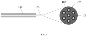
- Fig. 3 we illustrate the optical components of the apparatus and method according to the present disclosure, where fiber 100 is a multi-core optical fiber, Fig. 4 .
- Optical fiber 100 is shown with a typical protective acrylic coating 110.
- the fiber according to the present disclosure contains multiple single-mode cores within the standard 125 micron outer diameter, referred to as a multi-core fiber.
- the fiber end face 102 reveals 7 discrete cores, a central core 103, surrounded by 6 cores 104 in a hexagonal configuration, Fig. 4 .
- a transmitted optical communications signals emitted from the output end face of optical fiber 100 diverges at an angle ⁇ , defined by the fiber's numerical aperture (NA).
- NA numerical aperture
- the light beam In order to transmit the optical signal over a given distance, the light beam must be collimated in order to minimize the signal divergence and thereby, the channel insertion loss, and provide a signal amplitude high enough for the receiver to detect an error free signal. This is achieved by placing an optical fiber 100 at the focal point 101 of lens 112.
- the optical beam impinges on receiving lens 132 and the transmitting cores are imaged onto the corresponding cores in fiber 130 resulting in 3 duplex free-space optical communication channels.
- optical positioners are utilized.
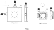
- Fig. 6 we show typical optical positioners, which can be utilized to perform the necessary alignment of the disclosed optical system.
- Liner positioner 201 provides controlled displacements in the lateral x-y directions perpendicular to the optic axis
- positioner 202 provides rotational displacements around the optic axis defined by the central cores 103 of multi-core fibers 100 and 130. In this scenario, rotational alignment is required to position the 6 cores surrounding 103.
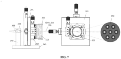
- Fig. 7 we show one embodiment of the present disclosure.
- Lens 112 is mounted in lens assembly 200 , mounted on positioner 202, and centered on the optic axis.
- a rotational alignment is required to align the surrounding cores. This can be achieved by utilizing one more pair of mating cores to monitored and adjust the angular positioner 202 to align the radially offset cores.
- One exemplary method to adjust the angular rotation is to add two 90:10 1 x2 fiber splitters to two of the fanned out cores to monitor the power for alignment. In this way, all the 7 channels can still be used for data center communication.
- power monitoring for the surrounding cores is done by tapping into a power of the channel of one of the surrounding cores by using an optical splitter with less than 30% tapped power.
- an at least three-core multicore fiber with one central core and two surrounding cores is used and lateral and angular alignment of the multicore fiber is achieved using one or more of the surrounding cores.
- power monitoring for the surrounding cores is done by tapping into the power of the communication channel by using an optical splitter with less than 30% tapped power.
- Access to the discrete cores 103 and 104 in said multi-core optical fibers 100 and 130 is achieved by means of a fiber core breakout cable 125, Fig. 9 .
- the discrete cores are broken out into (in this example) 1 simplex LC 126 connecting to core 103 , while cores 104 are terminated in 6 LC connectors grouped into 3 duplex core pairs 131, 132, and 133, for duplex communications.
- the multi-core fiber 100 can be terminated in a standard LC connector 129, held in position by means of an LC adapter 250 rigidly held in place by 240.
- the central fiber core 103 terminated in LC 129 is aligned on the optic axis at the focal point.
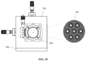
- Fig. 10 shows the positional relationship between the alignment stages and multi-core optical fiber.
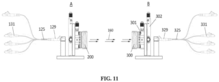
- the basic optical system in accordance to the present disclosure is illustrated in Fig. 11 .
- Fig. 11 we trace the path of a nominal optical communication signal.
- An optical communication signal transported in a single-mode fiber is coupled into the free-space apparatus according to the present disclosure via duplex connector 131.
- the signal is coupled into one of the cores of a multi-core optical fiber 125, held in position and aligned to the optic axis by means of apparatus A.
- the signal emanates from the output of connector 129, positioned at the focal point of lens 200.
- the essentially parallel optical beam traverses the free-space region between apparatus A and apparatus B.
- the signal is imaged by means of lens 300 into the end face of a corresponding core of said multi-core fiber terminated in receiving connector 329.
- the signal is then routed to connector 331, forming a communication channel.
- one of the external cores 104 can be used for channel monitoring and alignment and connected to LC 126, while cores 103 and rest of 104 core in 3 LC duplex connectors 131,132 133.
- the latter arrangement can improve the angular alignment of the system.
- raceway 520 is a polymer material, enclosed with lid, and two end caps, not shown.
- Optical communications and alignment of the multiple cores, relative to the optic axis, can be achieved by means of the two optical subsystems A and B shown in Fig. 11 .
- the two opposing optical subsystems A and B can be programmed, via control circuit 510, and optical tracking circuitry, not described in this disclosure.
- Fiber pigtails 141, 142, and 143 Access to the fiber cores utilized for optical communications can be achieved using fiber pigtails 141, 142, and 143 and connector interfaces 250.
Landscapes
- Physics & Mathematics (AREA)
- General Physics & Mathematics (AREA)
- Optics & Photonics (AREA)
- Electromagnetism (AREA)
- Engineering & Computer Science (AREA)
- Computer Networks & Wireless Communication (AREA)
- Signal Processing (AREA)
- Optical Couplings Of Light Guides (AREA)
Abstract
Description
- The present invention generally relates to the field of high-speed optical fiber communication channels and, more specifically, to a low latency optical channel. The disclosed apparatus and method enables optical communication signals to propagate through free-space, thereby traveling at the speed of light in air minimizing propagation time. The disclosed apparatus and method provides low latency optical signal paths for a multiplicity of discrete channels equalizing the propagation delay between adjacent channels.
- Free-space optical communications (in various forms) has been used for thousands of years. The ancient Greeks used a coded alphabetic system of signals to communicate utilizing torches. In 1880, Alexander Graham Bell created the photophone, which he considered his most important invention and was the world's first wireless telephone. Bell demonstrated voice communications over free-space optics between two building some 213 meters apart. During the trench warfare of World War I, red filtered light signals provided undetected communications at night. Currently, free-space optical communications is widely used in commercial, military, and space applications.
- Today, large data centers utilize optical fiber communications to achieve the high-speed and long channel reaches required for the switch-to-switch and switch-to-server interconnections. In the field of high-speed trading in financial markets, traders demand minimum transaction delay and guaranteed equivalent optical signal delay compared to other traders. Presently, these high-speed transactions propagate over standard single-mode and/or multimode optical fibers. To guarantee equivalent trading delays, optical fiber cable assemblies are custom manufactured where the discrete fiber lengths within said cable are precisely measured using optical time domain reflectometers (OTDRs) to ensure the optical channel delays are equivalent.
- To reduce the propagation delay of the optical channel, fiber manufacturers are developing hollow core fibers, where the core is a channel of air surrounded by an array of hollow tubes which form reflective micro-structures cladding, to confine the optical beam,
Fig. 1 . However, these fiber types are extremely difficult to manufacture in high volume and hence, are extremely expensive, i.e., hundreds to thousands of dollars per meter. Hollow core fibers also exhibit high attenuation (insertion loss) due to the coupling of the light's electromagnetic fields with the surrounding fiber core structure. In addition, due to the highly controlled spacing between fiber core elements, these fiber types and are very fragile and susceptible of degradation in performance as a result of bending. Consequently, hollow core fibers must have a robust cable design, and have a large bend radius not to deform or damage the core structure. - Hence, there is a need for a low cost solution where, the optical signal propagates near that of the speed of light in vacuum so that channels of said communication signals undergo minimum delay, and traders can be guaranteed equivalent optical channel paths.
- The speed of an optical signal is determined by the refractive index of the medium in which it propagates, where the refractive index is effectively the optical dielectric constant of the medium. The refractive index, n, is defined by,

- The authors of this disclosure measured the refractive index, and hence the optical signal delay in a commercially available hollow core fiber (hcf). The refractive index was found to be nhcf =1 .000476, yielding a 0.0476% delay compared to vacuum.
- In
Fig. 2 , we show an image of an exposed endface of said testedhollow core fiber 100, where the optical signal propagates as a fundamental mode within the central hollow core region, 101 (air), and the sixfeatures 102 which serve to optimize the optical performance of the hollow core fiber. - A low latency free-space optical data communication channel has at least two opposing optical collimators for transmitting an optical communication signal in the form of a parallel beam across a free-space channel. The input of the collimators are multi-core optical fibers. Multiple cores of the multi-core optical fibers are positioned at the focal point of the two opposing optical collimators. The optical collimators image the communications signals in each of the cores of the multi-core fibers into the corresponding cores of the opposing multi-core fibers.
- Optionally, the low latency free-space optical data communication channel further comprises a seven-core multicore fiber with one central core and six surrounding cores, and the lateral alignment of multicore fibers is achieved using the central core and the angular alignment is achieved using the one or more of the surrounding cores. Further optionally, in the low latency free-space optical data communication channel, power monitoring for the surrounding cores is done by tapping into a power of the channel of one of the surrounding cores by using an optical splitter with less than 30% tapped power.
- Optionally, the low latency free-space optical data communication channel comprises an at least three-core multicore fiber with one central core and two surrounding cores and lateral and angular alignment of the multicore fiber is achieved using one or more of the surrounding cores. Further optionally, in the low latency free-space optical data communication channel, power monitoring for the surrounding cores is done by tapping into the power of that channel by using an optical splitter with less than 30% tapped power.
-
-
Fig. 1 shows cross-sectional views of various hollow core optical fibers. -
Fig. 2 shows an image of an exposed endface of a tested hollow core fiber. -
Fig. 3 illustrates the optical components of the apparatus and method according to the present disclosure. -
Fig. 4 illustrates a fiber with multiple single-mode cores according to the present disclosure. -
Fig. 5 further illustrates the concept ofFig. 3 in order to make an optical channel according to the present disclosure. -
Fig. 6 shows optical positioners, which can be used with the present disclosure. -
Fig. 7 shows a first embodiment of the present disclosure. -
Fig. 8 illustrates the importance of rotational alignment. -
Fig. 9 shows how a fiber core breakout cable can be used with the present disclosure. -
Fig. 10 shows the positional relationship between the alignment stages and multi-core optical fiber. -
Fig. 11 traces the path of a nominal optical communication signal according to the present disclosure. -
Fig. 12 shows how a channel raceway can be sued to contain the collimated light path. -
Fig. 13 shows how the optical alignment of two multiple cores can be achieved through the use of two optical subsystems. - In the present disclosure, we disclose apparatus and method for free-space optical communication channels to be used in high speed low latency applications, where the channels do not have to utilize expensive hollow core fibers. Free-space optical communications requires three necessary conditions; line-of-sight, an unobstructed optical path, i.e., channel, and the divergence of the optical beam must be minimized. In
Fig. 3 , we illustrate the optical components of the apparatus and method according to the present disclosure, wherefiber 100 is a multi-core optical fiber,Fig. 4 . -
Optical fiber 100 is shown with a typical protectiveacrylic coating 110. However, the fiber according to the present disclosure contains multiple single-mode cores within the standard 125 micron outer diameter, referred to as a multi-core fiber. In this case, thefiber end face 102 reveals 7 discrete cores, acentral core 103, surrounded by 6cores 104 in a hexagonal configuration,Fig. 4 . - For this fiber core configuration, we can utilize
core 103 for optical alignment functions while the remaining cores can be used to support 3 duplex optical communication channels. The optical channel is shown inFig. 5 . - A transmitted optical communications signals emitted from the output end face of
optical fiber 100, diverges at an angle θ, defined by the fiber's numerical aperture (NA). In order to transmit the optical signal over a given distance, the light beam must be collimated in order to minimize the signal divergence and thereby, the channel insertion loss, and provide a signal amplitude high enough for the receiver to detect an error free signal. This is achieved by placing anoptical fiber 100 at thefocal point 101 oflens 112. - The multiple optical communication signals emanating from the 7 discrete cores of
fiber 100, positioned at the focal point oflens 112 produced acollimated beam 160. The optical beam impinges on receivinglens 132 and the transmitting cores are imaged onto the corresponding cores infiber 130 resulting in 3 duplex free-space optical communication channels. - In order to align said
optical fibers lenses Fig. 6 we show typical optical positioners, which can be utilized to perform the necessary alignment of the disclosed optical system. -
Liner positioner 201 provides controlled displacements in the lateral x-y directions perpendicular to the optic axis, whereaspositioner 202 provides rotational displacements around the optic axis defined by thecentral cores 103 ofmulti-core fibers Fig. 7 , we show one embodiment of the present disclosure.Lens 112 is mounted inlens assembly 200 , mounted onpositioner 202, and centered on the optic axis. - As illustrated in
Fig. 8 , it is insufficient to only align the central core. A rotational alignment is required to align the surrounding cores. This can be achieved by utilizing one more pair of mating cores to monitored and adjust theangular positioner 202 to align the radially offset cores. One exemplary method to adjust the angular rotation is to add two 90:10 1 x2 fiber splitters to two of the fanned out cores to monitor the power for alignment. In this way, all the 7 channels can still be used for data center communication. Optionally, power monitoring for the surrounding cores is done by tapping into a power of the channel of one of the surrounding cores by using an optical splitter with less than 30% tapped power. - In an alternative implementation, an at least three-core multicore fiber with one central core and two surrounding cores is used and lateral and angular alignment of the multicore fiber is achieved using one or more of the surrounding cores. In this alternative implementation, power monitoring for the surrounding cores is done by tapping into the power of the communication channel by using an optical splitter with less than 30% tapped power.
- Access to the
discrete cores optical fibers core breakout cable 125,Fig. 9 . Utilizing a specialized manufacturing process, the discrete cores are broken out into (in this example) 1simplex LC 126 connecting tocore 103 , whilecores 104 are terminated in 6 LC connectors grouped into 3 duplex core pairs 131, 132, and 133, for duplex communications. Themulti-core fiber 100 can be terminated in astandard LC connector 129, held in position by means of anLC adapter 250 rigidly held in place by 240. Thecentral fiber core 103 terminated inLC 129, is aligned on the optic axis at the focal point. -
Fig. 10 shows the positional relationship between the alignment stages and multi-core optical fiber. The basic optical system in accordance to the present disclosure is illustrated inFig. 11 . As an example, referring toFig. 11 we trace the path of a nominal optical communication signal. An optical communication signal transported in a single-mode fiber is coupled into the free-space apparatus according to the present disclosure viaduplex connector 131. The signal is coupled into one of the cores of a multi-coreoptical fiber 125, held in position and aligned to the optic axis by means of apparatus A. The signal emanates from the output ofconnector 129, positioned at the focal point oflens 200. The essentially parallel optical beam traverses the free-space region between apparatus A and apparatus B. The signal is imaged by means oflens 300 into the end face of a corresponding core of said multi-core fiber terminated in receivingconnector 329. The signal is then routed toconnector 331, forming a communication channel. - Alternatively, one of the
external cores 104 can be used for channel monitoring and alignment and connected toLC 126, whilecores 103 and rest of 104 core in 3 LC duplex connectors 131,132 133. The latter arrangement can improve the angular alignment of the system. - To protect and enclose the low latency free-space optical channel for communication applications according to the present disclosure, the collimated light path is enclosed within a
channel raceway 520 as those commonly used to carry fiber optic cables,Fig. 12 . The use of commercial data center raceways provides all the necessary hardware, installation practices, and industry certifications for safe use. In the preferred implementation,raceway 520 is a polymer material, enclosed with lid, and two end caps, not shown. - Optical communications and alignment of the multiple cores, relative to the optic axis, can be achieved by means of the two optical subsystems A and B shown in
Fig. 11 . Utilizing the central cores of the two opposing multi-core fibers 103 (Fig. 2 ), and automatedlinear positioners Fig. 13 , the two opposing optical subsystems A and B can be programmed, viacontrol circuit 510, and optical tracking circuitry, not described in this disclosure. - Access to the fiber cores utilized for optical communications can be achieved using
fiber pigtails - While particular embodiments and applications of the present invention have been illustrated and described, it is to be understood that the invention is not limited to the precise construction and compositions disclosed herein and that various modifications, changes, and variations may be apparent from the foregoing without departing from the scope of the invention as described.
Claims (5)
- A low latency free-space optical data communication channel comprising:
at least two opposing optical collimators for transmitting an optical communication signal in the form of a parallel beam across a free-space channel wherein the input of the collimators are multi-core optical fibers, multiple cores of the multi-core optical fibers are positioned at the focal point of the two opposing optical collimators, and the optical collimators image the communications signals in each of the cores of the multi-core fibers into the corresponding cores of the opposing multi-core fibers. - The low latency free-space optical data communication channel of claim 1 further comprising a seven-core multicore fiber with one central core and six surrounding cores wherein the lateral alignment of multicore fibers is achieved using the central core and the angular alignment is achieved using the one or more of the surrounding cores.
- The low latency free-space optical data communication channel of claim 2, wherein power monitoring for the surrounding cores is done by tapping into a power of the channel of one of the surrounding cores by using an optical splitter with less than 30% tapped power.
- The low latency free-space optical data communication channel of claim 1, wherein an at least three-core multicore fiber with one central core and two surrounding cores is used and lateral and angular alignment of the multicore fiber is achieved using one or more of the surrounding cores.
- The low latency free-space optical data communication channel of claim 4, wherein power monitoring for the surrounding cores is done by tapping into the power of that channel by using an optical splitter with less than 30% tapped power.
Applications Claiming Priority (1)
| Application Number | Priority Date | Filing Date | Title |
|---|---|---|---|
| US17/955,676 US12468089B2 (en) | 2022-09-29 | 2022-09-29 | Apparatus and method for low latency free-space optical communications |
Publications (2)
| Publication Number | Publication Date |
|---|---|
| EP4345518A1 true EP4345518A1 (en) | 2024-04-03 |
| EP4345518B1 EP4345518B1 (en) | 2026-04-22 |
Family
ID=88204225
Family Applications (1)
| Application Number | Title | Priority Date | Filing Date |
|---|---|---|---|
| EP23198381.8A Active EP4345518B1 (en) | 2022-09-29 | 2023-09-19 | Apparatus and method for low latency free-space optical communications |
Country Status (2)
| Country | Link |
|---|---|
| US (1) | US12468089B2 (en) |
| EP (1) | EP4345518B1 (en) |
Families Citing this family (1)
| Publication number | Priority date | Publication date | Assignee | Title |
|---|---|---|---|---|
| US20230393354A1 (en) * | 2022-06-07 | 2023-12-07 | Panduit Corp. | Apparatus and Method for Implementing Low Latency Optical Channels |
Citations (12)
| Publication number | Priority date | Publication date | Assignee | Title |
|---|---|---|---|---|
| WO2012088361A2 (en) * | 2010-12-21 | 2012-06-28 | Ofs Fitel, Llc | Multicore collimator |
| US20130088771A1 (en) * | 2011-10-05 | 2013-04-11 | Guifang Li | Systems And Methods For Amplifying Space-Multiplexed Optical Signals |
| US20150168642A1 (en) * | 2011-06-16 | 2015-06-18 | Tohoku Gakuin | Optical coupling structure and optical fiber amplifier |
| WO2018181132A1 (en) * | 2017-03-31 | 2018-10-04 | 国立研究開発法人情報通信研究機構 | High-speed multicore batch optical switch system |
| US20180359024A1 (en) * | 2015-11-26 | 2018-12-13 | Nippon Telegraph And Telephone Corporation | Communication system and fault detection method |
| US10234632B1 (en) * | 2015-08-18 | 2019-03-19 | National Technology & Engineering Solutions Of Sandia, Llc | Connectors for multicore optical fibers and methods thereof |
| US20190379175A1 (en) * | 2018-06-12 | 2019-12-12 | Sumitomo Electric Industries, Ltd. | Optical fiber amplifier |
| US20200310047A1 (en) * | 2019-03-26 | 2020-10-01 | Fathom Computing | Expanded Beam Multicore Fiber Connector |
| US20210026075A1 (en) * | 2019-07-23 | 2021-01-28 | Sumitomo Electric Industries, Ltd. | Optical connecting structure for connecting multi-core fibers |
| WO2021245774A1 (en) * | 2020-06-02 | 2021-12-09 | 日本電信電話株式会社 | Optical monitor device |
| US20210389525A1 (en) * | 2018-10-15 | 2021-12-16 | Sumitomo Electric Industries, Ltd. | Optical module and method for manufacturing optical module |
| US20210399514A1 (en) * | 2018-10-01 | 2021-12-23 | Nec Corporation | Optical amplification apparatus and optical amplification method |
Family Cites Families (6)
| Publication number | Priority date | Publication date | Assignee | Title |
|---|---|---|---|---|
| FR2781613B1 (en) | 1998-07-27 | 2000-10-06 | Photonetics | FREE SPACE LASER WITH SELF-ALIGNED FIBER OUTPUT |
| US6208784B1 (en) * | 1998-12-07 | 2001-03-27 | Multiplex Raceway Systems, Inc. | Fiber optic multiple access system |
| US7218811B2 (en) * | 2002-01-10 | 2007-05-15 | The Furukawa Electric Co., Ltd. | Optical module, and multi-core optical collimator and lens housing therefor |
| CA2938632C (en) * | 2014-04-25 | 2019-02-12 | Halliburton Energy Services, Inc. | Mounted downhole fiber optics accessory carrier body |
| US11199668B1 (en) * | 2020-07-28 | 2021-12-14 | Cisco Technology, Inc. | Coupling multi-channel laser to multicore fiber |
| US20230393354A1 (en) * | 2022-06-07 | 2023-12-07 | Panduit Corp. | Apparatus and Method for Implementing Low Latency Optical Channels |
-
2022
- 2022-09-29 US US17/955,676 patent/US12468089B2/en active Active
-
2023
- 2023-09-19 EP EP23198381.8A patent/EP4345518B1/en active Active
Patent Citations (12)
| Publication number | Priority date | Publication date | Assignee | Title |
|---|---|---|---|---|
| WO2012088361A2 (en) * | 2010-12-21 | 2012-06-28 | Ofs Fitel, Llc | Multicore collimator |
| US20150168642A1 (en) * | 2011-06-16 | 2015-06-18 | Tohoku Gakuin | Optical coupling structure and optical fiber amplifier |
| US20130088771A1 (en) * | 2011-10-05 | 2013-04-11 | Guifang Li | Systems And Methods For Amplifying Space-Multiplexed Optical Signals |
| US10234632B1 (en) * | 2015-08-18 | 2019-03-19 | National Technology & Engineering Solutions Of Sandia, Llc | Connectors for multicore optical fibers and methods thereof |
| US20180359024A1 (en) * | 2015-11-26 | 2018-12-13 | Nippon Telegraph And Telephone Corporation | Communication system and fault detection method |
| WO2018181132A1 (en) * | 2017-03-31 | 2018-10-04 | 国立研究開発法人情報通信研究機構 | High-speed multicore batch optical switch system |
| US20190379175A1 (en) * | 2018-06-12 | 2019-12-12 | Sumitomo Electric Industries, Ltd. | Optical fiber amplifier |
| US20210399514A1 (en) * | 2018-10-01 | 2021-12-23 | Nec Corporation | Optical amplification apparatus and optical amplification method |
| US20210389525A1 (en) * | 2018-10-15 | 2021-12-16 | Sumitomo Electric Industries, Ltd. | Optical module and method for manufacturing optical module |
| US20200310047A1 (en) * | 2019-03-26 | 2020-10-01 | Fathom Computing | Expanded Beam Multicore Fiber Connector |
| US20210026075A1 (en) * | 2019-07-23 | 2021-01-28 | Sumitomo Electric Industries, Ltd. | Optical connecting structure for connecting multi-core fibers |
| WO2021245774A1 (en) * | 2020-06-02 | 2021-12-09 | 日本電信電話株式会社 | Optical monitor device |
Also Published As
| Publication number | Publication date |
|---|---|
| EP4345518B1 (en) | 2026-04-22 |
| US12468089B2 (en) | 2025-11-11 |
| US20240118493A1 (en) | 2024-04-11 |
Similar Documents
| Publication | Publication Date | Title |
|---|---|---|
| US4252403A (en) | Coupler for a graded index fiber | |
| EP3807684B1 (en) | High-density optical fiber ribbon and ribbon cable interconnects employing small diameter optical fibers | |
| US4234969A (en) | Bidirectional optical coupler for a data processing system | |
| US6185346B1 (en) | Propagation in lowest order modes of multimode graded index fiber, resulting in: very low transmission loss, low modal noise, high data security, and high data rate capabilities | |
| JP7660655B2 (en) | Optical input/output device | |
| EP4064468B1 (en) | Optical coupler and optical amplifier | |
| EP4345518B1 (en) | Apparatus and method for low latency free-space optical communications | |
| WO2018222533A1 (en) | Pluggable fiber loopback apparatus and methods for fiber optical systems | |
| US20240264363A1 (en) | Ultra-Wideband Low Latency Multicore to Multicore Free-Space Optical Communications Using Parabolic Mirrors | |
| US4840482A (en) | Method of coated fiber identification in optical transmission network | |
| US20230393354A1 (en) | Apparatus and Method for Implementing Low Latency Optical Channels | |
| Nagase | Optical connectivities for multicore fiber | |
| US20240085632A1 (en) | Optical cross-connect device | |
| CN109870774A (en) | An integrated miniature 2-core attenuation optical cable assembly and manufacturing process | |
| CN113589422A (en) | Easily-identified multi-core optical fiber | |
| CN104272152A (en) | Multimode Multicore Fiber Connections with Expanded Beam | |
| EP4312069A2 (en) | Apparatus for implementing low latency optical channels | |
| CN113219594B (en) | Fast optical fiber coupler for optical fiber telephone | |
| Shimakawa et al. | Connector type fan-out device for multi-core fiber | |
| US10795078B2 (en) | MMF optical mode conditioning device | |
| Takahata et al. | Compact tap-isolator module using multicore fibre with practically low loss and small loss-variation | |
| EP4542275A1 (en) | Optical module | |
| WO2025179509A1 (en) | Multicore fiber with fan-in fan-out design | |
| CN111897056B (en) | Collimator manufacturing device and method for spatial disturbance removal mode | |
| CN115016072B (en) | Method for improving coupling efficiency of optical device |
Legal Events
| Date | Code | Title | Description |
|---|---|---|---|
| PUAI | Public reference made under article 153(3) epc to a published international application that has entered the european phase |
Free format text: ORIGINAL CODE: 0009012 |
|
| STAA | Information on the status of an ep patent application or granted ep patent |
Free format text: STATUS: THE APPLICATION HAS BEEN PUBLISHED |
|
| AK | Designated contracting states |
Kind code of ref document: A1 Designated state(s): AL AT BE BG CH CY CZ DE DK EE ES FI FR GB GR HR HU IE IS IT LI LT LU LV MC ME MK MT NL NO PL PT RO RS SE SI SK SM TR |
|
| STAA | Information on the status of an ep patent application or granted ep patent |
Free format text: STATUS: REQUEST FOR EXAMINATION WAS MADE |
|
| 17P | Request for examination filed |
Effective date: 20241003 |
|
| RBV | Designated contracting states (corrected) |
Designated state(s): AL AT BE BG CH CY CZ DE DK EE ES FI FR GB GR HR HU IE IS IT LI LT LU LV MC ME MK MT NL NO PL PT RO RS SE SI SK SM TR |
|
| GRAP | Despatch of communication of intention to grant a patent |
Free format text: ORIGINAL CODE: EPIDOSNIGR1 |
|
| STAA | Information on the status of an ep patent application or granted ep patent |
Free format text: STATUS: GRANT OF PATENT IS INTENDED |
|
| RIC1 | Information provided on ipc code assigned before grant |
Ipc: G02B 6/02 20060101AFI20251201BHEP Ipc: G02B 6/32 20060101ALI20251201BHEP Ipc: H04B 10/11 20130101ALI20251201BHEP Ipc: H04B 10/112 20130101ALI20251201BHEP Ipc: H04B 10/2581 20130101ALI20251201BHEP Ipc: H04B 10/079 20130101ALN20251201BHEP |
|
| INTG | Intention to grant announced |
Effective date: 20251212 |
|
| RIC1 | Information provided on ipc code assigned before grant |
Ipc: G02B 6/02 20060101AFI20251205BHEP Ipc: G02B 6/32 20060101ALI20251205BHEP Ipc: H04B 10/11 20130101ALI20251205BHEP Ipc: H04B 10/112 20130101ALI20251205BHEP Ipc: H04B 10/2581 20130101ALI20251205BHEP Ipc: H04B 10/079 20130101ALN20251205BHEP |
|
| GRAS | Grant fee paid |
Free format text: ORIGINAL CODE: EPIDOSNIGR3 |
|
| GRAA | (expected) grant |
Free format text: ORIGINAL CODE: 0009210 |
|
| STAA | Information on the status of an ep patent application or granted ep patent |
Free format text: STATUS: THE PATENT HAS BEEN GRANTED |
|
| AK | Designated contracting states |
Kind code of ref document: B1 Designated state(s): AL AT BE BG CH CY CZ DE DK EE ES FI FR GB GR HR HU IE IS IT LI LT LU LV MC ME MK MT NL NO PL PT RO RS SE SI SK SM TR |
|
| REG | Reference to a national code |
Ref country code: CH Ref legal event code: F10 Free format text: ST27 STATUS EVENT CODE: U-0-0-F10-F00 (AS PROVIDED BY THE NATIONAL OFFICE) Effective date: 20260422 Ref country code: GB Ref legal event code: FG4D |
|
| REG | Reference to a national code |
Ref country code: DE Ref legal event code: R096 Ref document number: 602023015625 Country of ref document: DE |