EP4345503A1 - Laser rangefinder with magnetic suction - Google Patents
Laser rangefinder with magnetic suction Download PDFInfo
- Publication number
- EP4345503A1 EP4345503A1 EP23200021.6A EP23200021A EP4345503A1 EP 4345503 A1 EP4345503 A1 EP 4345503A1 EP 23200021 A EP23200021 A EP 23200021A EP 4345503 A1 EP4345503 A1 EP 4345503A1
- Authority
- EP
- European Patent Office
- Prior art keywords
- shell
- laser rangefinder
- magnetic suction
- laser
- disposed
- Prior art date
- Legal status (The legal status is an assumption and is not a legal conclusion. Google has not performed a legal analysis and makes no representation as to the accuracy of the status listed.)
- Granted
Links
Images


Classifications
-
- G—PHYSICS
- G01—MEASURING; TESTING
- G01S—RADIO DIRECTION-FINDING; RADIO NAVIGATION; DETERMINING DISTANCE OR VELOCITY BY USE OF RADIO WAVES; LOCATING OR PRESENCE-DETECTING BY USE OF THE REFLECTION OR RERADIATION OF RADIO WAVES; ANALOGOUS ARRANGEMENTS USING OTHER WAVES
- G01S17/00—Systems using the reflection or reradiation of electromagnetic waves other than radio waves, e.g. lidar systems
- G01S17/02—Systems using the reflection of electromagnetic waves other than radio waves
- G01S17/06—Systems determining position data of a target
- G01S17/08—Systems determining position data of a target for measuring distance only
-
- G—PHYSICS
- G01—MEASURING; TESTING
- G01S—RADIO DIRECTION-FINDING; RADIO NAVIGATION; DETERMINING DISTANCE OR VELOCITY BY USE OF RADIO WAVES; LOCATING OR PRESENCE-DETECTING BY USE OF THE REFLECTION OR RERADIATION OF RADIO WAVES; ANALOGOUS ARRANGEMENTS USING OTHER WAVES
- G01S7/00—Details of systems according to groups G01S13/00, G01S15/00, G01S17/00
- G01S7/48—Details of systems according to groups G01S13/00, G01S15/00, G01S17/00 of systems according to group G01S17/00
- G01S7/481—Constructional features, e.g. arrangements of optical elements
- G01S7/4811—Constructional features, e.g. arrangements of optical elements common to transmitter and receiver
- G01S7/4813—Housing arrangements
-
- G—PHYSICS
- G01—MEASURING; TESTING
- G01S—RADIO DIRECTION-FINDING; RADIO NAVIGATION; DETERMINING DISTANCE OR VELOCITY BY USE OF RADIO WAVES; LOCATING OR PRESENCE-DETECTING BY USE OF THE REFLECTION OR RERADIATION OF RADIO WAVES; ANALOGOUS ARRANGEMENTS USING OTHER WAVES
- G01S7/00—Details of systems according to groups G01S13/00, G01S15/00, G01S17/00
- G01S7/48—Details of systems according to groups G01S13/00, G01S15/00, G01S17/00 of systems according to group G01S17/00
- G01S7/51—Display arrangements
Definitions
- the disclosure relates to the technical field of measuring device, and particularly to a laser rangefinder with magnetic suction.
- a laser rangefinder is a high-precision measuring instrument, which processes an emitted laser beam and a laser beam reflected back by a targeted object to obtain a distance between the laser rangefinder and the targeted object.
- the laser rangefinder is a necessary tool for construction and decoration professionals, which is frequently used, especially on the high-altitude metal frame.
- the existing laser rangefinder cannot be fixed on the metal frame, it still needs to be held and fixed by a user, which causes problems such as inconvenient operation and easy falling.
- the disclosure provides a laser rangefinder with magnetic suction, which solves the technical problems of the existing laser rangefinder, such as inconvenient operation and easy falling due to the need to hold the existing laser rangefinder.
- an embodiment of the disclosure provides a laser rangefinder with magnetic suction
- the laser rangefinder with magnetic suction includes a first shell, a second shell, a display screen, a control button, a laser ranging device and a magnet device configured (i.e., structured and arranged) to fix the laser rangefinder on a metal frame by magnetic suction.
- a front end of the first shell is provided with the display screen and the control button.
- a first accommodating cavity is formed between the first shell and the second shell, the laser ranging device is disposed in the first accommodating cavity, and the magnet device is disposed on the second shell.
- the magnetic device is disposed on an outer surface of the second shell.
- the magnet device is fixed on the outer surface of the second shell by adhesion.
- the magnet device and the second shell are an integrated forming structure.
- a rear side of the display screen is connected to the laser ranging device, and the outer surface of the second shell is provided with a battery installation groove recessed along an internal direction of the second shell.
- a second accommodating cavity is formed among the battery installation groove, the laser ranging device and the second shell, and the magnet device is disposed in the second accommodating cavity.
- the magnet device is fixed on an inner surface of the second shell by adhesion.
- the magnet device is fixed on the inner surface of the second shell by screw connection.
- a gap is arranged between the laser ranging device disposed in a rear side surface of the second accommodating cavity and a front end surface of the magnet device.
- the front end of the first shell is provided with a leveling device.
- the leveling device includes a first level instrument and a second level instrument; the control button and the second level instrument are disposed at a first side of the display screen, the first level instrument is disposed at a second side of the display screen, and a direction of the first side is perpendicular to a direction of the second side.
- the laser rangefinder with magnetic suction is provided with the magnet device, so that the laser rangefinder can be attached to the metal frame through the magnet device, which makes the measurement more convenient.
- the laser rangefinder with magnetic suction avoids the problems of inaccurate measurement caused by shaking hands in the handheld process, which can also ensure the accuracy of the measurement results.
- the laser rangefinder proposed in an embodiment of the disclosure is added a magnet device inside or on an external surface of the traditional handheld laser rangefinder, so that the laser rangefinder can be attached to a metal frame through the magnet device, thus making the measurement more convenient.
- the laser rangefinder avoids the problem of inaccurate measurement caused by hand shaking during the existing handheld process, which can ensure the accuracy of measurement results.
- a laser rangefinder with magnetic suction includes a first shell 5, a second shell 1, a display screen 11, a control button 7, a laser ranging device 4 and a magnet device 3 configured to fix the laser rangefinder on a metal frame 10 by magnetic suction.
- the laser ranging device 4 is configured to emit a laser to a measured object surface to measure a numerical value
- the display screen 11 is configured to display the numerical value measured by the laser ranging device 4
- the control button 7 is configured to control on-off and measurement of the laser ranging device 4.
- first shell 5 can also be referred to as an upper shell
- second shell 1 can also be referred to as a bottom shell.
- the display screen 11 and the control button 7 are disposed at a front end of the first shell 5, and the control button 7 is disposed on a first side of the display screen 11 (e.g., as shown in FIG. 1 , the control button 7 is disposed above the display screen 11).
- the first shell 5 and the second shell 1 is detachably connected, so that a first accommodating cavity can be formed between the first shell 5 and the second shell 1, and the laser ranging device 4 and the magnet device 3 are both disposed in the first accommodating cavity.
- a rear side of the display screen 11 (e.g., an arrow direction in FIG 2 represents a direction from a front side to the rear side) and the laser ranging device are fixedly connected.
- An outer surface of the second shell 1 is provided with a battery installation groove recessed along an internal direction of the second shell 1, a second accommodating cavity is formed among the battery installation groove, the laser ranging device 4, and the second shell 1 (i.e., a bottom wall of the second shell 1 and a side wall of the laser ranging device 4, and a side wall of the battery installation groove are enclosed to form the second accommodating cavity), and the magnet device 3 is disposed in the second accommodating cavity.
- the laser rangefinder further includes a battery 8 used to supply power to the laser ranging device 4 and the display screen 11 and a battery cover 9 adapted to the battery installation groove.
- the specific number, size and setting form of the magnet device 3 can be set according to the actual needs, as long as it is ensured that the laser rangefinder can be fixed on the metal frame (e.g., an iron frame) by magnetic suction, and the embodiment of the disclosure is not limited to the situation.
- the metal frame e.g., an iron frame
- the magnet device 3 is fixed on an inner surface of the second shell by adhesion.
- the magnet device 3 can be fixed on the bottom wall of the second shell 1 through a double-sided adhesive 2.
- the magnet device is fixed on an inner surface of the second shell by screw connection.
- the magnet device 3 can be fixed to the bottom wall of the second shell 1 by screws.
- a gap is arranged between the laser ranging device 4 disposed in a rear side surface 41 of the second accommodating cavity and a front end surface of the magnet device 3, thereby avoiding the problem of the magnet device 3 not being firmly fixed due to the squeezing of the magnet device 3 caused by the laser ranging device 4.
- the front end of the first shell 5 is provided with a horizontal device used to determine whether the laser rangefinder is in a horizontal state.
- the horizontal device can include a first level instrument 121.
- the control button 7 disposed at the first side of the display screen 11, and the first level instrument 121 disposed at a second side of the display screen 11, and a direction of the first side the display screen 11 is perpendicular to a direction of the second side the display screen 11.
- the horizontal device can further include a second level instrument 122, which is disposed at a side of the control button, and the first level instrument 121 and the second level instrument 122 can be fixed inside the first shell 5.
- the laser rangefinder can further include a display lens 6, which can be fixed outside the first shell 5.
- first shell 5 and the second shell 1 can both be made of polytetrafluoroethylene, which has advantages of falling resistance, high temperature resistance and corrosion resistance, so that the shells can effectively protect the internal parts of the laser rangefinder.
- the magnet device 3 can be a common magnet, which can achieve function of magnetic suction without the need for electrification or other ways.
- the display 11 can be a liquid crystal display (LCD) screen.
- LCD liquid crystal display
- the magnet device 3 can also be disposed on the outer surface of the second shell 1.
- the magnetic device 3 can be disposed on an outer surface of the battery cover 9 of the second shell 1, and the magnet device 3 can be disposed on a side of the battery installation groove.
- a size and a fixing method of the magnet device 3 can be set according to actual needs, and the embodiments of the disclosure are not limited to the situation.
- the magnet device 3 is fixed on the outer surface of the second shell 1 by adhesion.
- the magnet device 3 and the second shell 1 are integrally formed, the second shell 1 and the magnet device 3 can be placed together in a mold to form an integrated forming structure.
- the laser rangefinder proposed in the embodiment of the disclosure is added the magnet device inside or on the external surface of the traditional handheld laser rangefinder, so that the laser rangefinder can be attached to the metal frame through the magnet device, thus making the measurement more convenient. Moreover, it can also ensure the accuracy of the measurement results because it avoids the problem of inaccurate measurement caused by shaking hands in the existing handheld process.
- the laser rangefinder is only illustrative, and those skilled in the art can make various deformations according to the above methods, and the contents after modification or deformation are also within the protection scope of the disclosure.
- the terms “installation”, “connected”, “connection”, “fixed” and other terms should be broadly understood, for example, they can be fixed connection, detachable connection, or integrated. It can be a mechanical connection or an electrical connection. It can be directly connected or indirectly connected through an intermediate medium. It can be the internal connection between two components or the interaction relationship between two components.
- installation can be fixed connection, detachable connection, or integrated. It can be a mechanical connection or an electrical connection. It can be directly connected or indirectly connected through an intermediate medium. It can be the internal connection between two components or the interaction relationship between two components.
- a first feature disposed “above” or “below” a second feature can be understood that the first feature is in direct contact with the second feature or the first feature is in indirect contact with the second feature through an intermediate medium.
- the first feature disposed “on”, “up”, and “above” the second feature can be that the first feature is directly or obliquely above the second feature, or simply indicating a horizontal height of the first feature is higher than that of the second feature.
- the first feature deposed “under”, “down”, and “below” the second feature can be directly or obliquely below the first feature, or simply indicating that the horizontal height of the first feature is lower than that of the second feature.
- the terms “an embodiment”, “some embodiments”, “embodiments”, “examples”, “specific examples”, or “some examples” mean that the specific features, structures, materials, or characteristic described in conjunction with the embodiment or example are included in at least one embodiment or example of the disclosure.
- the schematic expressions of the above terms do not necessarily refer to the same embodiments or examples.
- the specific features, structures, materials, or characteristic described can be combined in an appropriate manner in any one or more embodiments or examples.
- the different embodiments or examples and the features of the different embodiments or examples described in this specification may be combined and incorporated by those skilled in the art without mutual contradiction.
Landscapes
- Engineering & Computer Science (AREA)
- Physics & Mathematics (AREA)
- Computer Networks & Wireless Communication (AREA)
- General Physics & Mathematics (AREA)
- Radar, Positioning & Navigation (AREA)
- Remote Sensing (AREA)
- Electromagnetism (AREA)
- Optical Radar Systems And Details Thereof (AREA)
- Measurement Of Optical Distance (AREA)
Abstract
Description
- The disclosure relates to the technical field of measuring device, and particularly to a laser rangefinder with magnetic suction.
- A laser rangefinder is a high-precision measuring instrument, which processes an emitted laser beam and a laser beam reflected back by a targeted object to obtain a distance between the laser rangefinder and the targeted object.
- At present, the laser rangefinder is a necessary tool for construction and decoration professionals, which is frequently used, especially on the high-altitude metal frame.
- However, since the existing laser rangefinder cannot be fixed on the metal frame, it still needs to be held and fixed by a user, which causes problems such as inconvenient operation and easy falling.
- In view of the above shortcomings and deficiencies of the related art, the disclosure provides a laser rangefinder with magnetic suction, which solves the technical problems of the existing laser rangefinder, such as inconvenient operation and easy falling due to the need to hold the existing laser rangefinder.
- In order to achieve the above purposes, the main technical solutions adopted by the disclosure are as follows.
- Specifically, an embodiment of the disclosure provides a laser rangefinder with magnetic suction, the laser rangefinder with magnetic suction includes a first shell, a second shell, a display screen, a control button, a laser ranging device and a magnet device configured (i.e., structured and arranged) to fix the laser rangefinder on a metal frame by magnetic suction. A front end of the first shell is provided with the display screen and the control button. A first accommodating cavity is formed between the first shell and the second shell, the laser ranging device is disposed in the first accommodating cavity, and the magnet device is disposed on the second shell.
- In an embodiment, the magnetic device is disposed on an outer surface of the second shell.
- In an embodiment, the magnet device is fixed on the outer surface of the second shell by adhesion.
- In an embodiment, the magnet device and the second shell are an integrated forming structure.
- In an embodiment, a rear side of the display screen is connected to the laser ranging device, and the outer surface of the second shell is provided with a battery installation groove recessed along an internal direction of the second shell. A second accommodating cavity is formed among the battery installation groove, the laser ranging device and the second shell, and the magnet device is disposed in the second accommodating cavity.
- In an embodiment, the magnet device is fixed on an inner surface of the second shell by adhesion.
- In an embodiment, the magnet device is fixed on the inner surface of the second shell by screw connection.
- In an embodiment, a gap is arranged between the laser ranging device disposed in a rear side surface of the second accommodating cavity and a front end surface of the magnet device.
- In an embodiment, the front end of the first shell is provided with a leveling device.
- In an embodiment, the leveling device includes a first level instrument and a second level instrument; the control button and the second level instrument are disposed at a first side of the display screen, the first level instrument is disposed at a second side of the display screen, and a direction of the first side is perpendicular to a direction of the second side.
- The benefits of the disclosure are as follows.
- The laser rangefinder with magnetic suction is provided with the magnet device, so that the laser rangefinder can be attached to the metal frame through the magnet device, which makes the measurement more convenient. The laser rangefinder with magnetic suction avoids the problems of inaccurate measurement caused by shaking hands in the handheld process, which can also ensure the accuracy of the measurement results.
-
-
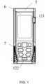
FIG. 1 illustrates a front view diagram of a laser rangefinder with magnetic suction according to an embodiment of the disclosure. -
FIG. 2 illustrates a side view schematic diagram of a cross section of the laser rangefinder with magnetic suction according to the embodiment of the disclosure. -
FIG. 3 illustrates an exploded view of the laser rangefinder with magnetic suction according to the embodiment of the disclosure. - To solve the problems of inconvenient operation and easy falling of the existing handheld laser device, the laser rangefinder proposed in an embodiment of the disclosure is added a magnet device inside or on an external surface of the traditional handheld laser rangefinder, so that the laser rangefinder can be attached to a metal frame through the magnet device, thus making the measurement more convenient. The laser rangefinder avoids the problem of inaccurate measurement caused by hand shaking during the existing handheld process, which can ensure the accuracy of measurement results.
- In order to better understand the above technical solutions, illustrated embodiments of the disclosure will be described below in more detail with reference to the attached drawings. Although the illustrated embodiments of the disclosure are shown in the attached drawings, it should be understood that the disclosure can be implemented in various forms and should not be limited by the embodiments described herein. On the contrary, the embodiments are provided in order to understand the disclosure more clearly and thoroughly, and to fully convey the scope of the disclosure to those skilled in the art.
- As shown in
FIGS. 1-3 , a laser rangefinder with magnetic suction includes afirst shell 5, asecond shell 1, adisplay screen 11, acontrol button 7, alaser ranging device 4 and amagnet device 3 configured to fix the laser rangefinder on ametal frame 10 by magnetic suction. Thelaser ranging device 4 is configured to emit a laser to a measured object surface to measure a numerical value, thedisplay screen 11 is configured to display the numerical value measured by thelaser ranging device 4, and thecontrol button 7 is configured to control on-off and measurement of thelaser ranging device 4. - It should be understood that the
first shell 5 can also be referred to as an upper shell, and thesecond shell 1 can also be referred to as a bottom shell. - In an embodiment, the
display screen 11 and thecontrol button 7 are disposed at a front end of thefirst shell 5, and thecontrol button 7 is disposed on a first side of the display screen 11 (e.g., as shown inFIG. 1 , thecontrol button 7 is disposed above the display screen 11). Thefirst shell 5 and thesecond shell 1 is detachably connected, so that a first accommodating cavity can be formed between thefirst shell 5 and thesecond shell 1, and thelaser ranging device 4 and themagnet device 3 are both disposed in the first accommodating cavity. - It should be understood that a specific layout of the
laser ranging device 4 and themagnet device 3 in the first accommodating cavity can be disposed according to actual needs, and the embodiments of the disclosure are not limited to the situation. - In an embodiment, as shown in
FIGS. 2-3 , a rear side of the display screen 11 (e.g., an arrow direction inFIG 2 represents a direction from a front side to the rear side) and the laser ranging device are fixedly connected. An outer surface of thesecond shell 1 is provided with a battery installation groove recessed along an internal direction of thesecond shell 1, a second accommodating cavity is formed among the battery installation groove, thelaser ranging device 4, and the second shell 1 (i.e., a bottom wall of thesecond shell 1 and a side wall of thelaser ranging device 4, and a side wall of the battery installation groove are enclosed to form the second accommodating cavity), and themagnet device 3 is disposed in the second accommodating cavity. The laser rangefinder further includes abattery 8 used to supply power to thelaser ranging device 4 and thedisplay screen 11 and abattery cover 9 adapted to the battery installation groove. - It should be understood that the specific number, size and setting form of the
magnet device 3 can be set according to the actual needs, as long as it is ensured that the laser rangefinder can be fixed on the metal frame (e.g., an iron frame) by magnetic suction, and the embodiment of the disclosure is not limited to the situation. - In an embodiment, the
magnet device 3 is fixed on an inner surface of the second shell by adhesion. - For example, as shown in
FIG. 1 , themagnet device 3 can be fixed on the bottom wall of thesecond shell 1 through a double-sided adhesive 2. - In an embodiment, the magnet device is fixed on an inner surface of the second shell by screw connection.
- For example, the
magnet device 3 can be fixed to the bottom wall of thesecond shell 1 by screws. - In an embodiment, as shown in
FIG. 2 , a gap is arranged between thelaser ranging device 4 disposed in arear side surface 41 of the second accommodating cavity and a front end surface of themagnet device 3, thereby avoiding the problem of themagnet device 3 not being firmly fixed due to the squeezing of themagnet device 3 caused by thelaser ranging device 4. - In an embodiment, as shown in
FIG. 1 , the front end of thefirst shell 5 is provided with a horizontal device used to determine whether the laser rangefinder is in a horizontal state. The horizontal device can include afirst level instrument 121. Thecontrol button 7 disposed at the first side of thedisplay screen 11, and thefirst level instrument 121 disposed at a second side of thedisplay screen 11, and a direction of the first side thedisplay screen 11 is perpendicular to a direction of the second side thedisplay screen 11. The horizontal device can further include asecond level instrument 122, which is disposed at a side of the control button, and thefirst level instrument 121 and thesecond level instrument 122 can be fixed inside thefirst shell 5. - In an embodiment, as shown in
FIGS. 1 and3 , the laser rangefinder can further include adisplay lens 6, which can be fixed outside thefirst shell 5. - It should be understood that the specific setting and relevant parameters of each device in the laser rangefinder can be set according to the actual needs, and the embodiment of the disclosure is not limited to the situation.
- In a specific embodiment, the
first shell 5 and thesecond shell 1 can both be made of polytetrafluoroethylene, which has advantages of falling resistance, high temperature resistance and corrosion resistance, so that the shells can effectively protect the internal parts of the laser rangefinder. - In a specific embodiment, the
magnet device 3 can be a common magnet, which can achieve function of magnetic suction without the need for electrification or other ways. - In a specific embodiment, the
display 11 can be a liquid crystal display (LCD) screen. - It should also be understood that although the laser rangefinder with magnetic suction is described above through
FIGS. 1 to 3 , those skilled in the art should understand that the laser rangefinder with magnetic suction can also be adjusted, and the embodiment of the disclosure is not limited to the situation. - In an embodiment, the
magnet device 3 can also be disposed on the outer surface of thesecond shell 1. - In a specific embodiment, the
magnetic device 3 can be disposed on an outer surface of thebattery cover 9 of thesecond shell 1, and themagnet device 3 can be disposed on a side of the battery installation groove. - It should be understood that a size and a fixing method of the
magnet device 3 can be set according to actual needs, and the embodiments of the disclosure are not limited to the situation. - In a specific embodiment, the
magnet device 3 is fixed on the outer surface of thesecond shell 1 by adhesion. - In a specific embodiment, the
magnet device 3 and thesecond shell 1 are integrally formed, thesecond shell 1 and themagnet device 3 can be placed together in a mold to form an integrated forming structure. - Therefore, the laser rangefinder proposed in the embodiment of the disclosure is added the magnet device inside or on the external surface of the traditional handheld laser rangefinder, so that the laser rangefinder can be attached to the metal frame through the magnet device, thus making the measurement more convenient. Moreover, it can also ensure the accuracy of the measurement results because it avoids the problem of inaccurate measurement caused by shaking hands in the existing handheld process.
- It should be understood that the laser rangefinder is only illustrative, and those skilled in the art can make various deformations according to the above methods, and the contents after modification or deformation are also within the protection scope of the disclosure.
- In the description of this disclosure, it should be understood that the terms "first" and "second" are only used for descriptive purposes and cannot be understood as indicating or implying relative importance or implying the number of indicated technical features. Therefore, features limited to "first" and "second" can explicitly or implicitly include one or more of these features. In the description of this disclosure, the meaning of "multiple" refers to two or more, unless otherwise specified.
- In the disclosure, unless otherwise specified and limited, the terms "installation", "connected", "connection", "fixed" and other terms should be broadly understood, for example, they can be fixed connection, detachable connection, or integrated. It can be a mechanical connection or an electrical connection. It can be directly connected or indirectly connected through an intermediate medium. It can be the internal connection between two components or the interaction relationship between two components. For those skilled in the art, the specific meanings of the above terms in this disclosure can be understood based on specific circumstances.
- In the disclosure, unless otherwise specified and limited, a first feature disposed "above" or "below" a second feature can be understood that the first feature is in direct contact with the second feature or the first feature is in indirect contact with the second feature through an intermediate medium. Moreover, the first feature disposed "on", "up", and "above" the second feature can be that the first feature is directly or obliquely above the second feature, or simply indicating a horizontal height of the first feature is higher than that of the second feature. The first feature deposed "under", "down", and "below" the second feature can be directly or obliquely below the first feature, or simply indicating that the horizontal height of the first feature is lower than that of the second feature.
- In the description of the specification, the terms "an embodiment", "some embodiments", "embodiments", "examples", "specific examples", or "some examples" mean that the specific features, structures, materials, or characteristic described in conjunction with the embodiment or example are included in at least one embodiment or example of the disclosure. In this specification, the schematic expressions of the above terms do not necessarily refer to the same embodiments or examples. Moreover, the specific features, structures, materials, or characteristic described can be combined in an appropriate manner in any one or more embodiments or examples. In addition, the different embodiments or examples and the features of the different embodiments or examples described in this specification may be combined and incorporated by those skilled in the art without mutual contradiction.
-
- 1
- second shell
- 2
- double-sided adhesive
- 3
- magnet device
- 4
- laser ranging device
- 5
- first shell
- 6
- display lens
- 7
- control button
- 8
- battery
- 9
- battery cover
- 10
- metal frame
- 11
- display screen
- 121
- first level instrument
- 122
- second level instrument
Claims (10)
- A laser rangefinder with magnetic suction, comprising:a first shell (5), a second shell (1), a display screen (11), a control button (7), a laser ranging device (4) and a magnet device (3) configured to fix the laser rangefinder on a metal frame (10) by the magnetic suction;wherein a front end of the first shell (5) is provided with the display screen (11) and the control button (7), a first accommodating cavity is formed between the first shell (5) and the second shell (1), the laser ranging device (4) is disposed in the first accommodating cavity, and the magnet device (3) is disposed on the second shell (1).
- The laser rangefinder with magnetic suction as claimed in claim 1, wherein the magnet device (3) is disposed on an outer surface of the second shell (1).
- The laser rangefinder with magnetic suction as claimed in claim 2, wherein the magnet device (3) is fixed on the outer surface of the second shell (1) by adhesion.
- The laser rangefinder with magnetic suction as claimed in claim 3, wherein the magnet device (3) and the second shell (1) are an integrated forming structure.
- The laser rangefinder with magnetic suction as claimed in one of the proceeding claims, wherein a rear side of the display screen (11) is connected to the laser ranging device (4), an outer surface of the second shell (1) is provided with a battery (8) installation groove recessed along an internal direction of the second shell (1), a second accommodating cavity is formed among the battery (8) installation groove, the laser ranging device (4) and the second shell (1), and the magnet device (3) is disposed in the second accommodating cavity.
- The laser rangefinder with magnetic suction as claimed in claim 5, wherein the magnet device (3) is fixed on an inner surface of the second shell (1) by adhesion.
- The laser rangefinder with magnetic suction as claimed in claim 5 or 6, wherein the magnet device (3) is fixed on an inner surface of the second shell (1) by screw connection.
- The laser rangefinder with magnetic suction as claimed in one of the claims 5 to 7, wherein a gap is arranged between the laser ranging device (4) disposed in a rear side surface of the second accommodating cavity and a front end surface of the magnet device (3).
- The laser rangefinder with magnetic suction as claimed in one of the proceeding claims, wherein the front end of the first shell (5) is provided with a leveling device.
- The laser rangefinder with magnetic suction as claimed in one of the claims 6 to 9, wherein the leveling device comprises a first level instrument (121) and a second level instrument, the control button (7) and the second level instrument are disposed at a first side of the display screen (11), the first level instrument (121) is disposed at a second side of the display screen (11), and a direction of the first side is perpendicular to a direction of the second side.
Applications Claiming Priority (1)
| Application Number | Priority Date | Filing Date | Title |
|---|---|---|---|
| CN202222615052.2U CN218630191U (en) | 2022-09-30 | 2022-09-30 | Laser range finder with magnetic attraction function |
Publications (3)
| Publication Number | Publication Date |
|---|---|
| EP4345503A1 true EP4345503A1 (en) | 2024-04-03 |
| EP4345503C0 EP4345503C0 (en) | 2025-10-29 |
| EP4345503B1 EP4345503B1 (en) | 2025-10-29 |
Family
ID=85468476
Family Applications (1)
| Application Number | Title | Priority Date | Filing Date |
|---|---|---|---|
| EP23200021.6A Active EP4345503B1 (en) | 2022-09-30 | 2023-09-27 | Laser rangefinder with magnetic suction |
Country Status (4)
| Country | Link |
|---|---|
| US (1) | US20240111026A1 (en) |
| EP (1) | EP4345503B1 (en) |
| CN (1) | CN218630191U (en) |
| PL (1) | PL4345503T3 (en) |
Families Citing this family (1)
| Publication number | Priority date | Publication date | Assignee | Title |
|---|---|---|---|---|
| CN220820238U (en) * | 2023-06-12 | 2024-04-19 | 深圳市迈测科技股份有限公司 | Laser distance measuring device |
Citations (3)
| Publication number | Priority date | Publication date | Assignee | Title |
|---|---|---|---|---|
| KR20170060286A (en) * | 2015-11-24 | 2017-06-01 | 진재삼 | Digital putting device for training |
| US20200200530A1 (en) * | 2018-12-21 | 2020-06-25 | Bushnell Inc. | Integral magnet mount for golf ranging device |
| CN216718682U (en) * | 2021-10-29 | 2022-06-10 | 深圳市恒天伟焱科技股份有限公司 | Magnetic attraction fixing mechanism and laser ranging telescope |
Family Cites Families (4)
| Publication number | Priority date | Publication date | Assignee | Title |
|---|---|---|---|---|
| US7894304B2 (en) * | 2007-06-29 | 2011-02-22 | Oneworld Solutions Limited | Project calculator with integral distance measurement sensor |
| JP2016175385A (en) * | 2015-03-23 | 2016-10-06 | セイコーエプソン株式会社 | Tape printer |
| WO2018185687A1 (en) * | 2017-04-04 | 2018-10-11 | Mo Drumsticks Llc | Magnetic resistance system for use with drum sets |
| US11474240B2 (en) * | 2019-01-07 | 2022-10-18 | Bushnell Inc. | Golf rangefinder device with integral magnet mount |
-
2022
- 2022-09-30 CN CN202222615052.2U patent/CN218630191U/en active Active
-
2023
- 2023-09-12 US US18/465,177 patent/US20240111026A1/en active Pending
- 2023-09-27 PL PL23200021.6T patent/PL4345503T3/en unknown
- 2023-09-27 EP EP23200021.6A patent/EP4345503B1/en active Active
Patent Citations (3)
| Publication number | Priority date | Publication date | Assignee | Title |
|---|---|---|---|---|
| KR20170060286A (en) * | 2015-11-24 | 2017-06-01 | 진재삼 | Digital putting device for training |
| US20200200530A1 (en) * | 2018-12-21 | 2020-06-25 | Bushnell Inc. | Integral magnet mount for golf ranging device |
| CN216718682U (en) * | 2021-10-29 | 2022-06-10 | 深圳市恒天伟焱科技股份有限公司 | Magnetic attraction fixing mechanism and laser ranging telescope |
Also Published As
| Publication number | Publication date |
|---|---|
| PL4345503T3 (en) | 2026-02-02 |
| CN218630191U (en) | 2023-03-14 |
| US20240111026A1 (en) | 2024-04-04 |
| EP4345503C0 (en) | 2025-10-29 |
| EP4345503B1 (en) | 2025-10-29 |
Similar Documents
| Publication | Publication Date | Title |
|---|---|---|
| EP4345503B1 (en) | Laser rangefinder with magnetic suction | |
| CN218002455U (en) | Double-laser non-contact thickness test equipment | |
| CN217111037U (en) | Lithium ion battery expansion volume measuring device | |
| CN206818201U (en) | A portable distance measuring device for engineering survey | |
| CN216082670U (en) | Accurate measurement and analysis device for carbon emission measurement | |
| CN212322020U (en) | Flatness detection device before touch-sensitive screen feeding in liquid crystal display module | |
| CN108716907A (en) | Horizontal measurement tool | |
| CN222317997U (en) | Building attachment thickness gauge | |
| CN212390930U (en) | A rapid measuring device of construction area for building inspection | |
| CN209147985U (en) | It is horizontally mounted detection device | |
| CN209214495U (en) | A kind of calibrator | |
| CN221745034U (en) | High-precision level measuring device | |
| CN218822854U (en) | Temperature measuring device | |
| CN207249117U (en) | Constant temperature laser ranging level meter | |
| CN222812472U (en) | Range-finding double-spectrum infrared thermal imager | |
| CN211425675U (en) | Temperature measuring and ranging instrument | |
| CN216558802U (en) | Portable ultrasonic thickness gauge | |
| CN220170207U (en) | Thickness gauge convenient to handheld operation | |
| CN222188279U (en) | A large-size inner diameter measuring instrument | |
| CN211626396U (en) | An accurate measuring instrument for concrete pouring thickness | |
| CN206387411U (en) | Detection ruler and detection instrument | |
| CN219586520U (en) | Measuring device for highway construction | |
| CN217305524U (en) | Handheld laser range finder for enhancing range finding accuracy | |
| CN219455001U (en) | Portable measurer | |
| CN221764483U (en) | A laser line orientation instrument that emits a light spot as a straight line or a cross line |
Legal Events
| Date | Code | Title | Description |
|---|---|---|---|
| PUAI | Public reference made under article 153(3) epc to a published international application that has entered the european phase |
Free format text: ORIGINAL CODE: 0009012 |
|
| STAA | Information on the status of an ep patent application or granted ep patent |
Free format text: STATUS: THE APPLICATION HAS BEEN PUBLISHED |
|
| AK | Designated contracting states |
Kind code of ref document: A1 Designated state(s): AL AT BE BG CH CY CZ DE DK EE ES FI FR GB GR HR HU IE IS IT LI LT LU LV MC ME MK MT NL NO PL PT RO RS SE SI SK SM TR |
|
| STAA | Information on the status of an ep patent application or granted ep patent |
Free format text: STATUS: REQUEST FOR EXAMINATION WAS MADE |
|
| 17P | Request for examination filed |
Effective date: 20240930 |
|
| RBV | Designated contracting states (corrected) |
Designated state(s): AL AT BE BG CH CY CZ DE DK EE ES FI FR GB GR HR HU IE IS IT LI LT LU LV MC ME MK MT NL NO PL PT RO RS SE SI SK SM TR |
|
| STAA | Information on the status of an ep patent application or granted ep patent |
Free format text: STATUS: EXAMINATION IS IN PROGRESS |
|
| 17Q | First examination report despatched |
Effective date: 20241211 |
|
| GRAP | Despatch of communication of intention to grant a patent |
Free format text: ORIGINAL CODE: EPIDOSNIGR1 |
|
| STAA | Information on the status of an ep patent application or granted ep patent |
Free format text: STATUS: GRANT OF PATENT IS INTENDED |
|
| INTG | Intention to grant announced |
Effective date: 20250731 |
|
| GRAS | Grant fee paid |
Free format text: ORIGINAL CODE: EPIDOSNIGR3 |
|
| GRAA | (expected) grant |
Free format text: ORIGINAL CODE: 0009210 |
|
| STAA | Information on the status of an ep patent application or granted ep patent |
Free format text: STATUS: THE PATENT HAS BEEN GRANTED |
|
| AK | Designated contracting states |
Kind code of ref document: B1 Designated state(s): AL AT BE BG CH CY CZ DE DK EE ES FI FR GB GR HR HU IE IS IT LI LT LU LV MC ME MK MT NL NO PL PT RO RS SE SI SK SM TR |
|
| REG | Reference to a national code |
Ref country code: CH Ref legal event code: F10 Free format text: ST27 STATUS EVENT CODE: U-0-0-F10-F00 (AS PROVIDED BY THE NATIONAL OFFICE) Effective date: 20251029 Ref country code: GB Ref legal event code: FG4D |
|
| REG | Reference to a national code |
Ref country code: IE Ref legal event code: FG4D |
|
| REG | Reference to a national code |
Ref country code: DE Ref legal event code: R096 Ref document number: 602023008000 Country of ref document: DE |
|
| U01 | Request for unitary effect filed |
Effective date: 20251127 |
|
| U07 | Unitary effect registered |
Designated state(s): AT BE BG DE DK EE FI FR IT LT LU LV MT NL PT RO SE SI Effective date: 20251204 |
|
| PG25 | Lapsed in a contracting state [announced via postgrant information from national office to epo] |
Ref country code: ES Free format text: LAPSE BECAUSE OF FAILURE TO SUBMIT A TRANSLATION OF THE DESCRIPTION OR TO PAY THE FEE WITHIN THE PRESCRIBED TIME-LIMIT Effective date: 20251029 |
|
| PG25 | Lapsed in a contracting state [announced via postgrant information from national office to epo] |
Ref country code: NO Free format text: LAPSE BECAUSE OF FAILURE TO SUBMIT A TRANSLATION OF THE DESCRIPTION OR TO PAY THE FEE WITHIN THE PRESCRIBED TIME-LIMIT Effective date: 20260129 |
|
| PG25 | Lapsed in a contracting state [announced via postgrant information from national office to epo] |
Ref country code: HR Free format text: LAPSE BECAUSE OF FAILURE TO SUBMIT A TRANSLATION OF THE DESCRIPTION OR TO PAY THE FEE WITHIN THE PRESCRIBED TIME-LIMIT Effective date: 20251029 |
|
| PG25 | Lapsed in a contracting state [announced via postgrant information from national office to epo] |
Ref country code: RS Free format text: LAPSE BECAUSE OF FAILURE TO SUBMIT A TRANSLATION OF THE DESCRIPTION OR TO PAY THE FEE WITHIN THE PRESCRIBED TIME-LIMIT Effective date: 20260129 |
|
| PG25 | Lapsed in a contracting state [announced via postgrant information from national office to epo] |
Ref country code: IS Free format text: LAPSE BECAUSE OF FAILURE TO SUBMIT A TRANSLATION OF THE DESCRIPTION OR TO PAY THE FEE WITHIN THE PRESCRIBED TIME-LIMIT Effective date: 20260228 |
|
| PG25 | Lapsed in a contracting state [announced via postgrant information from national office to epo] |
Ref country code: SM Free format text: LAPSE BECAUSE OF FAILURE TO SUBMIT A TRANSLATION OF THE DESCRIPTION OR TO PAY THE FEE WITHIN THE PRESCRIBED TIME-LIMIT Effective date: 20251029 |
|
| PG25 | Lapsed in a contracting state [announced via postgrant information from national office to epo] |
Ref country code: CZ Free format text: LAPSE BECAUSE OF FAILURE TO SUBMIT A TRANSLATION OF THE DESCRIPTION OR TO PAY THE FEE WITHIN THE PRESCRIBED TIME-LIMIT Effective date: 20251029 |
|
| PG25 | Lapsed in a contracting state [announced via postgrant information from national office to epo] |
Ref country code: SK Free format text: LAPSE BECAUSE OF FAILURE TO SUBMIT A TRANSLATION OF THE DESCRIPTION OR TO PAY THE FEE WITHIN THE PRESCRIBED TIME-LIMIT Effective date: 20251029 |