EP4345318A1 - Adjustable spacer - Google Patents
Adjustable spacer Download PDFInfo
- Publication number
- EP4345318A1 EP4345318A1 EP22315219.0A EP22315219A EP4345318A1 EP 4345318 A1 EP4345318 A1 EP 4345318A1 EP 22315219 A EP22315219 A EP 22315219A EP 4345318 A1 EP4345318 A1 EP 4345318A1
- Authority
- EP
- European Patent Office
- Prior art keywords
- component
- spacing
- support
- adjustable spacer
- spacer
- Prior art date
- Legal status (The legal status is an assumption and is not a legal conclusion. Google has not performed a legal analysis and makes no representation as to the accuracy of the status listed.)
- Granted
Links
Images


Classifications
-
- F—MECHANICAL ENGINEERING; LIGHTING; HEATING; WEAPONS; BLASTING
- F16—ENGINEERING ELEMENTS AND UNITS; GENERAL MEASURES FOR PRODUCING AND MAINTAINING EFFECTIVE FUNCTIONING OF MACHINES OR INSTALLATIONS; THERMAL INSULATION IN GENERAL
- F16B—DEVICES FOR FASTENING OR SECURING CONSTRUCTIONAL ELEMENTS OR MACHINE PARTS TOGETHER, e.g. NAILS, BOLTS, CIRCLIPS, CLAMPS, CLIPS OR WEDGES; JOINTS OR JOINTING
- F16B5/00—Joining sheets or plates, e.g. panels, to one another or to strips or bars parallel to them
- F16B5/02—Joining sheets or plates, e.g. panels, to one another or to strips or bars parallel to them by means of fastening members using screw-thread
- F16B5/0216—Joining sheets or plates, e.g. panels, to one another or to strips or bars parallel to them by means of fastening members using screw-thread the position of the plates to be connected being adjustable
- F16B5/0233—Joining sheets or plates, e.g. panels, to one another or to strips or bars parallel to them by means of fastening members using screw-thread the position of the plates to be connected being adjustable allowing for adjustment perpendicular to the plane of the plates
-
- F—MECHANICAL ENGINEERING; LIGHTING; HEATING; WEAPONS; BLASTING
- F16—ENGINEERING ELEMENTS AND UNITS; GENERAL MEASURES FOR PRODUCING AND MAINTAINING EFFECTIVE FUNCTIONING OF MACHINES OR INSTALLATIONS; THERMAL INSULATION IN GENERAL
- F16B—DEVICES FOR FASTENING OR SECURING CONSTRUCTIONAL ELEMENTS OR MACHINE PARTS TOGETHER, e.g. NAILS, BOLTS, CIRCLIPS, CLAMPS, CLIPS OR WEDGES; JOINTS OR JOINTING
- F16B35/00—Screw-bolts; Stay-bolts; Screw-threaded studs; Screws; Set screws
- F16B35/005—Set screws; Locking means therefor
-
- F—MECHANICAL ENGINEERING; LIGHTING; HEATING; WEAPONS; BLASTING
- F16—ENGINEERING ELEMENTS AND UNITS; GENERAL MEASURES FOR PRODUCING AND MAINTAINING EFFECTIVE FUNCTIONING OF MACHINES OR INSTALLATIONS; THERMAL INSULATION IN GENERAL
- F16B—DEVICES FOR FASTENING OR SECURING CONSTRUCTIONAL ELEMENTS OR MACHINE PARTS TOGETHER, e.g. NAILS, BOLTS, CIRCLIPS, CLAMPS, CLIPS OR WEDGES; JOINTS OR JOINTING
- F16B37/00—Nuts or like thread-engaging members
- F16B37/16—Wing-nuts
-
- F—MECHANICAL ENGINEERING; LIGHTING; HEATING; WEAPONS; BLASTING
- F16—ENGINEERING ELEMENTS AND UNITS; GENERAL MEASURES FOR PRODUCING AND MAINTAINING EFFECTIVE FUNCTIONING OF MACHINES OR INSTALLATIONS; THERMAL INSULATION IN GENERAL
- F16B—DEVICES FOR FASTENING OR SECURING CONSTRUCTIONAL ELEMENTS OR MACHINE PARTS TOGETHER, e.g. NAILS, BOLTS, CIRCLIPS, CLAMPS, CLIPS OR WEDGES; JOINTS OR JOINTING
- F16B39/00—Locking of screws, bolts or nuts
- F16B39/02—Locking of screws, bolts or nuts in which the locking takes place after screwing down
- F16B39/12—Locking of screws, bolts or nuts in which the locking takes place after screwing down by means of locknuts
Definitions
- the invention is related to an adjustable spacer for adjusting a spacing between a first component and a second component to a predefined distance.
- one or more first components and one or more second components need to be assembled in a predefined relationship with respect to each other.
- a predefined relationship may require adjustment of a spacing between the one or more first components and the one or more second components to a predefined distance, as the one or more first components and the one or more second components and, more generally, all manufactured components are subject to manufacturing tolerances and must be managed with respect to geometric tolerances and gaps.
- doorframes in fuselages of rotorcrafts must generally be fitted with tight tolerances into associated openings provided in the fuselages.
- distortion of the doorframes must be prevented as otherwise associated door panels may not be installed correctly in the doorframes.
- an operator in order to prevent an inaccurate mounting of a doorframe to an opening in a fuselage of a given rotorcraft, an operator usually initially measures a gap present between the doorframe and the fuselage. This generally requires an initial assembly of the doorframe and the fuselage by the operator. The operator must then determine respective parts or shims to be used for closing the measured gap and, subsequently, arrange the respective parts or shims in the gap between the doorframe and the fuselage. This, however, requires disassembly of the doorframe from the fuselage by the operator and a subsequent re-assembly of the doorframe and the fuselage together with the respective parts or shims.
- laminated shims are used to enable a required adjustment of doorframes in openings of fuselages of rotorcrafts.
- Such laminated shims may also be referred to as “peelable”, “peel-off” or “peel” shims and consist of laminated layers or foils which may be peeled-off and which may have a thickness of even only a few microns.
- any subsequent re-adjustment requires disassembly of the at least two different components as peeling off layers or foils from the laminated shims may only be done in disassembled state of the at least two different components.
- an object of the present invention to provide a new spacer for adjusting a spacing between a first component and a second component to a predefined distance, which enables adjustment of the spacing after assembly of the first and second components in a comparatively small period of time without requiring any measurements and whilst avoiding any disassembly of the first and second components.
- an adjustable spacer for adjusting a spacing between a first component and a second component to a predefined distance, the adjustable spacer comprising the features of claim 1.
- an adjustable spacer for adjusting a spacing between a first component and a second component to a predefined distance comprises at least a support component, a spacing component, and a fixing component.
- the support component is configured to be rigidly mounted to the first component.
- the spacing component is movably mounted to the support component for adjusting positioning of the support component relative to the second component.
- the fixing component is configured for locking the spacing component on the support component after the positioning of the support component relative to the second component at the predefined distance.
- the inventive adjustable spacer enables adjusting a spacing between a first component and a second component to a predefined distance after assembly of the first and second components in a comparatively small period of time without requiring any measurements and whilst avoiding any disassembly of the first and second components.
- adjusting of the spacing using the inventive adjustable spacer is simple and reliable, may be performed in any direction of the three-dimensional space that is enabled by the inventive adjustable spacer, and may easily and quickly be re-adjusted, if required.
- adjusting of the spacing is at any time reversible in any direction enabled by the inventive adjustable spacer. This leads to a significant reduction of time required for the adjusting of the spacing and, thus, to a significant reduction of costs.
- the support component comprises a support body supporting the spacing component, and at least one attachment portion configured to be rigidly mounted to the first component.
- the support body is embodied as a support ring with an inner thread.
- the at least one attachment portion is embodied as an attachment flange with at least one associated through hole configured to receive attachment means, in particular attachment screws or bolts.
- the spacing component is embodied as a threaded sleeve with an outer thread.
- the spacing component comprises tightening slits.
- the fixing component is embodied as a counter nut with an inner thread.
- the fixing component is removable to enable re-adjustment of the positioning of the support component relative to the second component to increase/decrease the predefined distance.
- the adjustable spacer further comprises a mounting component configured for rigidly mounting the spacing component to the second component after the locking of the spacing component on the support component.
- a suitable load transfer between the first and second components may be enabled.
- the mounting component is removable to enable re-adjustment of the positioning of the support component relative to the second component to increase/decrease the predefined distance.
- the mounting component is embodied as a mounting screw.
- the adjustable spacer further comprises a retaining element configured for retaining the mounting component on the spacing component.
- the retaining element is embodied as a washer.
- the support component, the spacing component, and the fixing component are exchangeable.
- the present invention is further related to an arrangement comprising a first component, a second component, and an adjustable spacer as described above for adjusting a spacing between the first component and the second component to a predefined distance.
- Figure 1 shows an adjustable spacer 1 according to the present invention, which comprises at least a support component 2, a spacing component 3, and a fixing component 4.
- the support component 2, the spacing component 3, and the fixing component 4 are exchangeable.
- the support component 2 is configured to be rigidly mounted to a first component (7 in Figure 3 to Figure 5 ).
- the spacing component 3 is movably mounted to the support component 2 for adjusting positioning of the support component 2 relative to a second component (8 in Figure 3 to Figure 5 ).
- the fixing component 4 is configured for locking the spacing component 3 on the support component 2 after the positioning of the support component 2 relative to the second component (8 in Figure 3 to Figure 5 ) at a predefined distance (9a in Figure 3 to Figure 5 ).
- the fixing component 4 is removable to enable re-adjustment of the positioning of the support component 2 relative to the second component (8 in Figure 3 to Figure 5 ) to increase/decrease the predefined distance (9a in Figure 3 to Figure 5 ).
- the support component 2 illustratively comprises a support body 2a supporting the spacing component 3, and at least one attachment portion 2c, 2e configured to be rigidly mounted to the first component (7 in Figure 3 to Figure 5 ).
- the support body 2a is embodied as a support ring with an inner thread 2b and, therefore, also referred to hereinafter as the "support ring 2a", for brevity and clarity.
- the at least one attachment portion 2c, 2e is illustratively embodied as an attachment flange with at least one associated through hole 2d, 2f configured to receive attachment means, in particular attachment screws or bolts.
- two attachment portions 2c, 2e are provided, each in the form of an attachment flange that extends away from the support ring 2a.
- the attachment portion 2c which is hereinafter referred to as the "attachment flange 2c”, for brevity and clarity
- the attachment portion 2e which is hereinafter referred to as the "attachment flange 2e"
- the through hole 2f is provided with the through hole 2f.
- the attachment flanges 2c, 2e may be formed integrally with the support ring 2a, i. e. as integral parts of a single piece. Alternatively, the attachment flanges 2c, 2e may be rigidly attached to the support ring 2a in any suitable manner.
- the support ring 2a preferably accommodates the spacing component 3 at least partly.
- the spacing component 3 is embodied as a threaded sleeve with an outer thread 3a and, therefore, also referred to hereinafter as the "threaded spacer 3", for brevity and clarity.
- the outer thread 3a of the threaded spacer 3 matches the inner thread 2b of the support ring 2a such that the threaded spacer 3 may be screwed into the inner thread 2b.
- the threaded spacer 3 which is embodied as a threaded sleeve comprises an inner through hole 3c and tightening slits 3b on diametrically opposed sides of the threaded sleeve.
- a slotted screwdriver may be used for screwing the threaded spacer 3 by means of its outer thread 3a into, or out of, the inner thread 2b of the support ring 2a.
- the fixing component 4 is embodied as a counter nut with an inner thread 4a and referred to hereinafter as the "counter nut 4", for brevity and clarity.
- the inner thread 4a of the counter nut 4 matches the outer thread 3a of the threaded spacer 3.
- the counter nut 4 may be screwed by means of its inner thread 4a onto the outer thread 3a of the threaded spacer 3 and blocked against the support ring 2a for blocking the threaded spacer 3 in the support ring 2a.
- a retaining element 5 and a mounting component 6 may be associated with the adjustable spacer 1.
- the retaining element 5 is embodied as a washer and, therefore, referred to hereinafter as the “washer 5", for brevity and clarity.
- the mounting component 6, in turn, is illustratively embodied as a mounting screw with an outer thread 6a and, therefore, referred to hereinafter as the “mounting screw 6", for brevity and clarity.
- mounting screw 6 is illustratively embodied as a mounting screw with an outer thread 6a and, therefore, referred to hereinafter as the “mounting screw 6", for brevity and clarity.
- Figure 2 shows the support component 2 of Figure 1 with the threaded spacer 3 of Figure 1 for further illustrating the through holes 2d, 2f, and 3c.
- the support component 2 comprises the support ring 2a with the inner thread 2b and the attachment flanges 2c, 2e which are provided with the through holes 2d, 2f.
- the threaded spacer 3 comprises the outer thread 3a, the tightening slits 3b, and the inner through hole 3c.
- the support component 2 is illustratively an essentially flat component.
- the support component 2 should not be restricted to a flat shape.
- the support component 2 may have other shapes, e. g. it may be arc-shaped or kinked, dependent on an intended use thereof, i. e. dependent on a shaping of a component to which it is mounted, such as component 7 in Figure 3 to Figure 5 .
- Figure 3 to Figure 5 show an illustrative use of the adjustable spacer 1 according to Figure 1 and Figure 2 for adjusting a spacing 9 between a first component 7 and a second component 8 to a predefined distance 9a.
- the first component 7 and the second component 8 are assembled to form an arrangement 10.
- the arrangement 10 may be a rotorcraft.
- the first component 7 may e. g. be a doorframe and the second component 8 may e. g. be a fuselage of the rotorcraft.
- the component 7 illustratively comprises a wall 7a with an opening 7b.
- the opening 7b accommodates at least partly the support ring 2a of the support component 2 of the adjustable spacer 1, which is provided with the threaded spacer 3 of the adjustable spacer 1.
- the support ring 2a is preferably rigidly attached to the wall 7a by means of the attachment flanges 2c, 2e of the adjustable spacer 1, which are, however, not visible due to the selected cutting line of the view.
- the threaded spacer 3 is illustratively screwed into the inner thread 2b of the support ring 2a by means of its outer thread 3a such that the threaded spacer 3 extends at least partly through the support ring 2a toward a wall 8a of the component 8, which further comprises a mounting plug 8b with an inner thread 8c provided at an opening 8d in the wall 8a. More specifically, the threaded spacer 3 is screwed into the inner thread 2b of the support ring 2a until it abuts against the wall 8a.
- the threaded spacer 3 may now be screwed further into the inner thread 2b of the support ring 2a to increase the spacing 9 between the walls 7a, 8a, or it may be screwed out of the inner thread 2b of the support ring 2a to decrease the spacing 9 between the walls 7a, 8a.
- the screwing of the threaded spacer 3 into or out of the inner thread 2b of the support ring 2a is performed until the spacing 9 is adjusted to the predefined distance 9a.
- the mounting screw 6 of the adjustable spacer 1 is now according to Figure 5 screwed into the mounting plug 8b. More specifically, the washer 5 of the adjustable spacer 1 is positioned on the threaded spacer 3 at the position of the tightening slits 3b and the mounting screw 6 is inserted through the washer 5, the inner through hole 3c of the threaded spacer 3, and the opening 8d in the wall 8a into the inner thread 8c of the mounting plug 8b, and tightened therein.
- the washer 5 is configured for retaining the mounting screw 6 on the threaded spacer 3.
- the mounting screw 6 rigidly mounts the threaded spacer 3 to the component 8 after the locking of the threaded spacer 3 on the support ring 2a in the component 7.
- the mounting screw 6 is removable to enable re-adjustment of the positioning of the support ring 2a relative to the component 8, for instance if it is subsequently necessary to increase/decrease the predefined distance 9a.
- the counter nut 4 is preferably also removable to enable re-adjustment of the positioning of the support ring 2a relative to the component 8 at any time.
- the threaded spacer 3 may be removable and also the support component 2 of the adjustable spacer 1.
Landscapes
- Engineering & Computer Science (AREA)
- General Engineering & Computer Science (AREA)
- Mechanical Engineering (AREA)
- Bolts, Nuts, And Washers (AREA)
- Connection Of Plates (AREA)
Abstract
Description
- The invention is related to an adjustable spacer for adjusting a spacing between a first component and a second component to a predefined distance.
- In various application fields one or more first components and one or more second components need to be assembled in a predefined relationship with respect to each other. Such a predefined relationship may require adjustment of a spacing between the one or more first components and the one or more second components to a predefined distance, as the one or more first components and the one or more second components and, more generally, all manufactured components are subject to manufacturing tolerances and must be managed with respect to geometric tolerances and gaps.
- By way of example, doorframes in fuselages of rotorcrafts must generally be fitted with tight tolerances into associated openings provided in the fuselages. However, distortion of the doorframes must be prevented as otherwise associated door panels may not be installed correctly in the doorframes.
- More specifically, in order to prevent an inaccurate mounting of a doorframe to an opening in a fuselage of a given rotorcraft, an operator usually initially measures a gap present between the doorframe and the fuselage. This generally requires an initial assembly of the doorframe and the fuselage by the operator. The operator must then determine respective parts or shims to be used for closing the measured gap and, subsequently, arrange the respective parts or shims in the gap between the doorframe and the fuselage. This, however, requires disassembly of the doorframe from the fuselage by the operator and a subsequent re-assembly of the doorframe and the fuselage together with the respective parts or shims.
- Frequently, laminated shims are used to enable a required adjustment of doorframes in openings of fuselages of rotorcrafts. Such laminated shims may also be referred to as "peelable", "peel-off" or "peel" shims and consist of laminated layers or foils which may be peeled-off and which may have a thickness of even only a few microns.
- However, also the use of such laminated shims in an adjustment problem of the type described above and, more generally, in an adjustment problem that necessitates respect of existing tolerances between at least two different components, usually requires several steps including at least assembly of the different components, measurement of present gaps, disassembly of the different components, determination of a suitable thickness of respective laminated shims, adjustment of the suitable thickness of the laminated shims by peeling off layers or foils, and reassembly of the different components with the laminated shims.
- Nevertheless, all these steps are time-consuming in production. They are even more time-consuming if the steps must be repeated, e. g. as a result of inaccurate measurements. Furthermore, any subsequent re-adjustment requires disassembly of the at least two different components as peeling off layers or foils from the laminated shims may only be done in disassembled state of the at least two different components.
- The documents
WO 2022/162090 A1 ,EP 3 915 870 A4 ,EP 3 983 288 A1 ,EP 3 476 714 A1 ,EP 3 239 038 A1 , andEP 1 217 136 A3 describe various spacers or spacing mechanisms for adjustment of spacings between different components at predefined distances. However, all these different solutions are rather complex and cost-intensive. - It is, therefore, an object of the present invention to provide a new spacer for adjusting a spacing between a first component and a second component to a predefined distance, which enables adjustment of the spacing after assembly of the first and second components in a comparatively small period of time without requiring any measurements and whilst avoiding any disassembly of the first and second components.
- This object is solved by an adjustable spacer for adjusting a spacing between a first component and a second component to a predefined distance, the adjustable spacer comprising the features of claim 1.
- More specifically, according to the present invention an adjustable spacer for adjusting a spacing between a first component and a second component to a predefined distance comprises at least a support component, a spacing component, and a fixing component. The support component is configured to be rigidly mounted to the first component. The spacing component is movably mounted to the support component for adjusting positioning of the support component relative to the second component. The fixing component is configured for locking the spacing component on the support component after the positioning of the support component relative to the second component at the predefined distance.
- Advantageously, the inventive adjustable spacer enables adjusting a spacing between a first component and a second component to a predefined distance after assembly of the first and second components in a comparatively small period of time without requiring any measurements and whilst avoiding any disassembly of the first and second components. In particular, adjusting of the spacing using the inventive adjustable spacer is simple and reliable, may be performed in any direction of the three-dimensional space that is enabled by the inventive adjustable spacer, and may easily and quickly be re-adjusted, if required.
- In other words, adjusting of the spacing is at any time reversible in any direction enabled by the inventive adjustable spacer. This leads to a significant reduction of time required for the adjusting of the spacing and, thus, to a significant reduction of costs.
- According to a preferred embodiment, the support component comprises a support body supporting the spacing component, and at least one attachment portion configured to be rigidly mounted to the first component.
- According to a further preferred embodiment, the support body is embodied as a support ring with an inner thread.
- According to a further preferred embodiment, the at least one attachment portion is embodied as an attachment flange with at least one associated through hole configured to receive attachment means, in particular attachment screws or bolts.
- According to a further preferred embodiment, the spacing component is embodied as a threaded sleeve with an outer thread.
- According to a further preferred embodiment, the spacing component comprises tightening slits.
- According to a further preferred embodiment, the fixing component is embodied as a counter nut with an inner thread.
- According to a further preferred embodiment, the fixing component is removable to enable re-adjustment of the positioning of the support component relative to the second component to increase/decrease the predefined distance.
- According to a further preferred embodiment, the adjustable spacer further comprises a mounting component configured for rigidly mounting the spacing component to the second component after the locking of the spacing component on the support component.
- Thus, a suitable load transfer between the first and second components may be enabled.
- According to a further preferred embodiment, the mounting component is removable to enable re-adjustment of the positioning of the support component relative to the second component to increase/decrease the predefined distance.
- According to a further preferred embodiment, the mounting component is embodied as a mounting screw.
- According to a further preferred embodiment, the adjustable spacer further comprises a retaining element configured for retaining the mounting component on the spacing component.
- According to a further preferred embodiment, the retaining element is embodied as a washer.
- According to a further preferred embodiment, the support component, the spacing component, and the fixing component are exchangeable.
- The present invention is further related to an arrangement comprising a first component, a second component, and an adjustable spacer as described above for adjusting a spacing between the first component and the second component to a predefined distance.
- Preferred embodiments of the invention are outlined by way of example in the following description with reference to the attached drawings. In these attached drawings, identical or identically functioning components and elements are labeled with identical reference numbers and characters and are, consequently, only described once in the following description.
-
Figure 1 shows a perspective exploded view of an adjustable spacer according to the present invention, with a support component, a spacing component, a fixing component, and a mounting component, -
Figure 2 shows a perspective view of the support component and the spacing component ofFigure 1 , and -
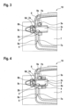
Figure 3 to Figure 5 show cut views of an illustrative utilization of the adjustable spacer ofFigure 1 for adjusting a spacing between a first component and a second component to a predefined distance. -
Figure 1 shows an adjustable spacer 1 according to the present invention, which comprises at least asupport component 2, aspacing component 3, and afixing component 4. Preferably, thesupport component 2, thespacing component 3, and thefixing component 4 are exchangeable. - More specifically, the
support component 2 is configured to be rigidly mounted to a first component (7 inFigure 3 to Figure 5 ). Thespacing component 3 is movably mounted to thesupport component 2 for adjusting positioning of thesupport component 2 relative to a second component (8 inFigure 3 to Figure 5 ). Thefixing component 4 is configured for locking thespacing component 3 on thesupport component 2 after the positioning of thesupport component 2 relative to the second component (8 inFigure 3 to Figure 5 ) at a predefined distance (9a inFigure 3 to Figure 5 ). Preferably, thefixing component 4 is removable to enable re-adjustment of the positioning of thesupport component 2 relative to the second component (8 inFigure 3 to Figure 5 ) to increase/decrease the predefined distance (9a inFigure 3 to Figure 5 ). - The
support component 2 illustratively comprises asupport body 2a supporting thespacing component 3, and at least oneattachment portion Figure 3 to Figure 5 ). By way of example, thesupport body 2a is embodied as a support ring with aninner thread 2b and, therefore, also referred to hereinafter as the "support ring 2a", for brevity and clarity. - Furthermore, the at least one
attachment portion hole attachment portions support ring 2a. Illustratively, theattachment portion 2c, which is hereinafter referred to as the "attachment flange 2c", for brevity and clarity, is provided with the throughhole 2d, and theattachment portion 2e, which is hereinafter referred to as the "attachment flange 2e", for brevity and clarity, is provided with the throughhole 2f. - The
attachment flanges support ring 2a, i. e. as integral parts of a single piece. Alternatively, theattachment flanges support ring 2a in any suitable manner. - Moreover, the
support ring 2a preferably accommodates thespacing component 3 at least partly. Illustratively, thespacing component 3 is embodied as a threaded sleeve with anouter thread 3a and, therefore, also referred to hereinafter as the "threadedspacer 3", for brevity and clarity. Theouter thread 3a of the threadedspacer 3 matches theinner thread 2b of thesupport ring 2a such that the threadedspacer 3 may be screwed into theinner thread 2b. - By way of example, the threaded
spacer 3 which is embodied as a threaded sleeve comprises an inner throughhole 3c and tighteningslits 3b on diametrically opposed sides of the threaded sleeve. Thus, for instance a slotted screwdriver may be used for screwing the threadedspacer 3 by means of itsouter thread 3a into, or out of, theinner thread 2b of thesupport ring 2a. - The threaded
spacer 3 is blocked in thesupport ring 2a by means of thefixing component 4. Illustratively, the fixingcomponent 4 is embodied as a counter nut with aninner thread 4a and referred to hereinafter as the "counter nut 4", for brevity and clarity. - The
inner thread 4a of thecounter nut 4 matches theouter thread 3a of the threadedspacer 3. Thus, thecounter nut 4 may be screwed by means of itsinner thread 4a onto theouter thread 3a of the threadedspacer 3 and blocked against thesupport ring 2a for blocking the threadedspacer 3 in thesupport ring 2a. - According to one aspect, a retaining
element 5 and a mountingcomponent 6 may be associated with the adjustable spacer 1. By way of example, the retainingelement 5 is embodied as a washer and, therefore, referred to hereinafter as the "washer 5", for brevity and clarity. The mountingcomponent 6, in turn, is illustratively embodied as a mounting screw with anouter thread 6a and, therefore, referred to hereinafter as the "mountingscrew 6", for brevity and clarity. Use of thewasher 5 and the mountingscrew 6 is explained in detail below atFigure 5 . -
Figure 2 shows thesupport component 2 ofFigure 1 with the threadedspacer 3 ofFigure 1 for further illustrating the throughholes support component 2 comprises thesupport ring 2a with theinner thread 2b and theattachment flanges holes spacer 3 comprises theouter thread 3a, the tighteningslits 3b, and the inner throughhole 3c. - It should be noted that the
support component 2 is illustratively an essentially flat component. However, thesupport component 2 should not be restricted to a flat shape. Instead, thesupport component 2 may have other shapes, e. g. it may be arc-shaped or kinked, dependent on an intended use thereof, i. e. dependent on a shaping of a component to which it is mounted, such ascomponent 7 inFigure 3 to Figure 5 . -
Figure 3 to Figure 5 show an illustrative use of the adjustable spacer 1 according toFigure 1 and Figure 2 for adjusting aspacing 9 between afirst component 7 and asecond component 8 to apredefined distance 9a. By way of example, thefirst component 7 and thesecond component 8 are assembled to form anarrangement 10. - For instance, the
arrangement 10 may be a rotorcraft. In this case, thefirst component 7 may e. g. be a doorframe and thesecond component 8 may e. g. be a fuselage of the rotorcraft. - More specifically, according to
Figure 3 thecomponent 7 illustratively comprises awall 7a with anopening 7b. Theopening 7b accommodates at least partly thesupport ring 2a of thesupport component 2 of the adjustable spacer 1, which is provided with the threadedspacer 3 of the adjustable spacer 1. Thesupport ring 2a is preferably rigidly attached to thewall 7a by means of theattachment flanges - The threaded
spacer 3 is illustratively screwed into theinner thread 2b of thesupport ring 2a by means of itsouter thread 3a such that the threadedspacer 3 extends at least partly through thesupport ring 2a toward awall 8a of thecomponent 8, which further comprises a mountingplug 8b with aninner thread 8c provided at anopening 8d in thewall 8a. More specifically, the threadedspacer 3 is screwed into theinner thread 2b of thesupport ring 2a until it abuts against thewall 8a. - The threaded
spacer 3 may now be screwed further into theinner thread 2b of thesupport ring 2a to increase thespacing 9 between thewalls inner thread 2b of thesupport ring 2a to decrease thespacing 9 between thewalls spacer 3 into or out of theinner thread 2b of thesupport ring 2a is performed until thespacing 9 is adjusted to thepredefined distance 9a. - According to
Figure 4 , when thespacing 9 is adjusted to thepredefined distance 9a, the threadedspacer 3 is locked in thesupport ring 2a by means of thecounter nut 4 that comprises theinner thread 4a. To this end, thecounter nut 4 is threaded by means of itsinner thread 4a on theouter thread 3a of the threadedspacer 3 until it is blocked against thesupport ring 2a of the adjustable spacer 1. Thus, thespacing 9 between thecomponents walls predefined distance 9a. - For reliably and securely locking the
components arrangement 10 at thepredefined distance 9a, the mountingscrew 6 of the adjustable spacer 1 is now according toFigure 5 screwed into the mountingplug 8b. More specifically, thewasher 5 of the adjustable spacer 1 is positioned on the threadedspacer 3 at the position of the tightening slits 3b and the mountingscrew 6 is inserted through thewasher 5, the inner throughhole 3c of the threadedspacer 3, and theopening 8d in thewall 8a into theinner thread 8c of the mountingplug 8b, and tightened therein. - The
washer 5 is configured for retaining the mountingscrew 6 on the threadedspacer 3. Thus, the mountingscrew 6 rigidly mounts the threadedspacer 3 to thecomponent 8 after the locking of the threadedspacer 3 on thesupport ring 2a in thecomponent 7. - Preferably, the mounting
screw 6 is removable to enable re-adjustment of the positioning of thesupport ring 2a relative to thecomponent 8, for instance if it is subsequently necessary to increase/decrease thepredefined distance 9a. Accordingly, thecounter nut 4 is preferably also removable to enable re-adjustment of the positioning of thesupport ring 2a relative to thecomponent 8 at any time. Similarly, the threadedspacer 3 may be removable and also thesupport component 2 of the adjustable spacer 1. -
- 1
- adjustable spacer
- 2
- spacer support
- 2a
- support body part
- 2b
- body part inner thread
- 2c, 2e
- attachment flanges
- 2d, 2f
- through holes
- 3
- threaded spacer
- 3a
- spacer outer thread
- 3b
- tightening slits
- 3c
- through hole
- 4
- counter nut
- 4a
- nut inner thread
- 5
- washer
- 6
- mounting screw
- 6a
- screw outer thread
- 7
- first component
- 7a
- first component wall
- 7b
- opening
- 8
- second component
- 8a
- second component wall
- 8b
- mounting plug
- 8c
- plug inner thread
- 8d
- opening
- 9
- spacing
- 9a
- predefined distance
- 10
- component arrangement
Claims (15)
- An adjustable spacer (1) for adjusting a spacing (9) between a first component (7) and a second component (8) to a predefined distance (9a); comprising at least:a support component (2) configured to be rigidly mounted to the first component (7);a spacing component (3) movably mounted to the support component (2) for adjusting positioning of the support component (2) relative to the second component (8); anda fixing component (4) configured for locking the spacing component (3) on the support component (2) after the positioning of the support component (2) relative to the second component (8) at the predefined distance (9a).
- The adjustable spacer (1) of claim 1, wherein the support component (2) comprises:a support body (2a) supporting the spacing component (3); andat least one attachment portion (2c, 2e) configured to be rigidly mounted to the first component (7).
- The adjustable spacer (1) of claim 2,
wherein the support body (2a) is embodied as a support ring with an inner thread (2b). - The adjustable spacer (1) of claim 2 or 3,
wherein the at least one attachment portion (2c, 2e) is embodied as an attachment flange with at least one associated through hole (2d, 2f) configured to receive attachment means, in particular attachment screws or bolts. - The adjustable spacer (1) of any one of the preceding claims,
wherein the spacing component (3) is embodied as a threaded sleeve with an outer thread (3a). - The adjustable spacer (1) of claim 5,
wherein the spacing component (3) comprises tightening slits (3b). - The adjustable spacer (1) of any one of the preceding claims,
wherein the fixing component (4) is embodied as a counter nut (4) with an inner thread (4a). - The adjustable spacer (1) of any one of the preceding claims, wherein the fixing component (4) is removable to enable re-adjustment of the positioning of the support component (2) relative to the second component (8) to increase/decrease the predefined distance (9a).
- The adjustable spacer (1) of any one of the preceding claims, further comprising a mounting component (6) configured for rigidly mounting the spacing component (3) to the second component (8) after the locking of the spacing component (3) on the support component (2).
- The adjustable spacer (1) of claim 9, wherein the mounting component (6) is removable to enable re-adjustment of the positioning of the support component (2) relative to the second component (8) to increase/decrease the predefined distance (9a).
- The adjustable spacer (1) of claim 9 or 10,
wherein the mounting component (6) is embodied as a mounting screw. - The adjustable spacer (1) of any one of claims 9 to 11, further comprising a retaining element (5) configured for retaining the mounting component (6) on the spacing component (3).
- The adjustable spacer (1) of claim 12,
wherein the retaining element (5) is embodied as a washer. - The adjustable spacer (1) of any one of the preceding claims,
wherein the support component (2), the spacing component (3), and the fixing component (4) are exchangeable. - An arrangement (10) comprising:a first component (7),a second component (8), andan adjustable spacer (1) according to any one of the preceding claims for adjusting a spacing (9) between the first component (7) and the second component (8) to a predefined distance (9a).
Priority Applications (1)
| Application Number | Priority Date | Filing Date | Title |
|---|---|---|---|
| EP22315219.0A EP4345318B1 (en) | 2022-09-27 | 2022-09-27 | Adjustable spacer |
Applications Claiming Priority (1)
| Application Number | Priority Date | Filing Date | Title |
|---|---|---|---|
| EP22315219.0A EP4345318B1 (en) | 2022-09-27 | 2022-09-27 | Adjustable spacer |
Publications (2)
| Publication Number | Publication Date |
|---|---|
| EP4345318A1 true EP4345318A1 (en) | 2024-04-03 |
| EP4345318B1 EP4345318B1 (en) | 2025-07-23 |
Family
ID=83899489
Family Applications (1)
| Application Number | Title | Priority Date | Filing Date |
|---|---|---|---|
| EP22315219.0A Active EP4345318B1 (en) | 2022-09-27 | 2022-09-27 | Adjustable spacer |
Country Status (1)
| Country | Link |
|---|---|
| EP (1) | EP4345318B1 (en) |
Citations (14)
| Publication number | Priority date | Publication date | Assignee | Title |
|---|---|---|---|---|
| US1440576A (en) * | 1920-07-03 | 1923-01-02 | Mh Treadwell Co | Metal structure and method of securing parts |
| US4108407A (en) * | 1975-07-14 | 1978-08-22 | Rca Corporation | Adjustment device |
| US4854844A (en) * | 1986-03-27 | 1989-08-08 | John Brown, Inc. | Die-lip adjusting mechanism |
| EP0533513A1 (en) * | 1991-09-20 | 1993-03-24 | Automobiles Peugeot | Adjustable fixing device with a threaded link |
| EP0543046A1 (en) * | 1991-11-22 | 1993-05-26 | Werner Simon | Screw unit |
| EP1217136A2 (en) | 2000-12-21 | 2002-06-26 | Sergio Zambelli | Anchoring device for prefabricated concrete components |
| US7588386B2 (en) * | 2006-08-30 | 2009-09-15 | Silicon Valley Automation | Leveling and aligning device |
| EP3239038A1 (en) | 2016-04-29 | 2017-11-01 | Embraer S.A. | Quick connection assemblies especially useful for coupling aircraft antenna fairings to airframe structures |
| WO2018048890A1 (en) * | 2016-09-06 | 2018-03-15 | Solarreserve Technology, Llc | Heliostat mirror panels with pivotable hardware modules |
| EP3476714A1 (en) | 2017-10-24 | 2019-05-01 | Embraer S.A. | Mechanisms, systems and methods to allow step-adjustment of aerodynamic surfaces |
| WO2019195724A1 (en) * | 2018-04-06 | 2019-10-10 | Nill Lance | Combined anchor, fastener and leveling assembly |
| EP3915870A1 (en) | 2020-05-28 | 2021-12-01 | Airbus Helicopters | Device for releasing a panel of an aircraft and associated aircraft |
| EP3983288A1 (en) | 2019-06-15 | 2022-04-20 | Latecoere | Aircraft door with adjustable support arm hinges |
| WO2022162090A1 (en) | 2021-01-28 | 2022-08-04 | Latecoere | Aircraft door equipped with a system for adjustment in position and method for installing such a door |
-
2022
- 2022-09-27 EP EP22315219.0A patent/EP4345318B1/en active Active
Patent Citations (14)
| Publication number | Priority date | Publication date | Assignee | Title |
|---|---|---|---|---|
| US1440576A (en) * | 1920-07-03 | 1923-01-02 | Mh Treadwell Co | Metal structure and method of securing parts |
| US4108407A (en) * | 1975-07-14 | 1978-08-22 | Rca Corporation | Adjustment device |
| US4854844A (en) * | 1986-03-27 | 1989-08-08 | John Brown, Inc. | Die-lip adjusting mechanism |
| EP0533513A1 (en) * | 1991-09-20 | 1993-03-24 | Automobiles Peugeot | Adjustable fixing device with a threaded link |
| EP0543046A1 (en) * | 1991-11-22 | 1993-05-26 | Werner Simon | Screw unit |
| EP1217136A2 (en) | 2000-12-21 | 2002-06-26 | Sergio Zambelli | Anchoring device for prefabricated concrete components |
| US7588386B2 (en) * | 2006-08-30 | 2009-09-15 | Silicon Valley Automation | Leveling and aligning device |
| EP3239038A1 (en) | 2016-04-29 | 2017-11-01 | Embraer S.A. | Quick connection assemblies especially useful for coupling aircraft antenna fairings to airframe structures |
| WO2018048890A1 (en) * | 2016-09-06 | 2018-03-15 | Solarreserve Technology, Llc | Heliostat mirror panels with pivotable hardware modules |
| EP3476714A1 (en) | 2017-10-24 | 2019-05-01 | Embraer S.A. | Mechanisms, systems and methods to allow step-adjustment of aerodynamic surfaces |
| WO2019195724A1 (en) * | 2018-04-06 | 2019-10-10 | Nill Lance | Combined anchor, fastener and leveling assembly |
| EP3983288A1 (en) | 2019-06-15 | 2022-04-20 | Latecoere | Aircraft door with adjustable support arm hinges |
| EP3915870A1 (en) | 2020-05-28 | 2021-12-01 | Airbus Helicopters | Device for releasing a panel of an aircraft and associated aircraft |
| WO2022162090A1 (en) | 2021-01-28 | 2022-08-04 | Latecoere | Aircraft door equipped with a system for adjustment in position and method for installing such a door |
Also Published As
| Publication number | Publication date |
|---|---|
| EP4345318B1 (en) | 2025-07-23 |
Similar Documents
| Publication | Publication Date | Title |
|---|---|---|
| EP2417020B1 (en) | Coupling assembly | |
| US20130014345A1 (en) | Hidden door hinge | |
| US20120242097A1 (en) | Pressure relief latch, high repeatability | |
| EP3792567A1 (en) | Bracket for walls | |
| EP0194032B1 (en) | Securing means | |
| EP4345318B1 (en) | Adjustable spacer | |
| BR102020018023A2 (en) | spacer assembly | |
| US12258996B2 (en) | Probe fastening system and aircraft | |
| EP0530132B1 (en) | Fastener with differentially inclined axes | |
| AU2025287332A1 (en) | Configurable base plate system for industrial pumps | |
| US7588272B2 (en) | Door handle assembly | |
| WO2017053551A1 (en) | Adjustable hinge to eliminate shimming | |
| CN109720543B (en) | Inlet and outlet cover | |
| US7229049B2 (en) | Unitized rotary actuator hinge fitting | |
| FI81428C (en) | CENTRERINGSANORDNING FOER FASTGOERING OCH CENTRERING AV ETT DOERRHANDTAG. | |
| BR102018071846B1 (en) | MECHANISMS, SYSTEMS AND METHODS TO ALLOW ADJUSTMENT OF GROWTH OF AERODYNAMIC SURFACES | |
| US4650229A (en) | Lock arrangement for a door panel | |
| CN102791947A (en) | Hinge units for doors, windows or the like | |
| US11542976B2 (en) | Tolerance compensator | |
| CN215169202U (en) | Split type glass door clamp | |
| US20210336335A1 (en) | Manual actuating device for phase shifter and supporting system | |
| CN222837218U (en) | Drawer adjusting device and refrigerator | |
| CN215922529U (en) | Honeycomb panel assembly | |
| CN224093199U (en) | Hinge structure with adjustable glass counter bore | |
| EP4153877B1 (en) | Locking system and manufacturing method thereof, bearing assembly and robot having the same |
Legal Events
| Date | Code | Title | Description |
|---|---|---|---|
| PUAI | Public reference made under article 153(3) epc to a published international application that has entered the european phase |
Free format text: ORIGINAL CODE: 0009012 |
|
| STAA | Information on the status of an ep patent application or granted ep patent |
Free format text: STATUS: THE APPLICATION HAS BEEN PUBLISHED |
|
| AK | Designated contracting states |
Kind code of ref document: A1 Designated state(s): AL AT BE BG CH CY CZ DE DK EE ES FI FR GB GR HR HU IE IS IT LI LT LU LV MC MK MT NL NO PL PT RO RS SE SI SK SM TR |
|
| STAA | Information on the status of an ep patent application or granted ep patent |
Free format text: STATUS: REQUEST FOR EXAMINATION WAS MADE |
|
| 17P | Request for examination filed |
Effective date: 20240405 |
|
| P01 | Opt-out of the competence of the unified patent court (upc) registered |
Effective date: 20240405 |
|
| RBV | Designated contracting states (corrected) |
Designated state(s): AL AT BE BG CH CY CZ DE DK EE ES FI FR GB GR HR HU IE IS IT LI LT LU LV MC MK MT NL NO PL PT RO RS SE SI SK SM TR |
|
| GRAP | Despatch of communication of intention to grant a patent |
Free format text: ORIGINAL CODE: EPIDOSNIGR1 |
|
| STAA | Information on the status of an ep patent application or granted ep patent |
Free format text: STATUS: GRANT OF PATENT IS INTENDED |
|
| RIC1 | Information provided on ipc code assigned before grant |
Ipc: F16B 39/12 20060101ALN20250410BHEP Ipc: F16B 37/16 20060101ALN20250410BHEP Ipc: F16B 35/00 20060101ALI20250410BHEP Ipc: F16B 5/02 20060101AFI20250410BHEP |
|
| INTG | Intention to grant announced |
Effective date: 20250424 |
|
| RIN1 | Information on inventor provided before grant (corrected) |
Inventor name: MORA, PAUL Inventor name: LE CADET, YANN |
|
| GRAS | Grant fee paid |
Free format text: ORIGINAL CODE: EPIDOSNIGR3 |
|
| GRAA | (expected) grant |
Free format text: ORIGINAL CODE: 0009210 |
|
| STAA | Information on the status of an ep patent application or granted ep patent |
Free format text: STATUS: THE PATENT HAS BEEN GRANTED |
|
| AK | Designated contracting states |
Kind code of ref document: B1 Designated state(s): AL AT BE BG CH CY CZ DE DK EE ES FI FR GB GR HR HU IE IS IT LI LT LU LV MC MK MT NL NO PL PT RO RS SE SI SK SM TR |
|
| REG | Reference to a national code |
Ref country code: GB Ref legal event code: FG4D |
|
| REG | Reference to a national code |
Ref country code: CH Ref legal event code: EP |
|
| REG | Reference to a national code |
Ref country code: IE Ref legal event code: FG4D |
|
| REG | Reference to a national code |
Ref country code: DE Ref legal event code: R096 Ref document number: 602022018023 Country of ref document: DE |
|
| PGFP | Annual fee paid to national office [announced via postgrant information from national office to epo] |
Ref country code: DE Payment date: 20250919 Year of fee payment: 4 |
|
| PGFP | Annual fee paid to national office [announced via postgrant information from national office to epo] |
Ref country code: AT Payment date: 20251020 Year of fee payment: 4 Ref country code: FR Payment date: 20250922 Year of fee payment: 4 |
|
| REG | Reference to a national code |
Ref country code: NL Ref legal event code: MP Effective date: 20250723 |
|
| PG25 | Lapsed in a contracting state [announced via postgrant information from national office to epo] |
Ref country code: PT Free format text: LAPSE BECAUSE OF FAILURE TO SUBMIT A TRANSLATION OF THE DESCRIPTION OR TO PAY THE FEE WITHIN THE PRESCRIBED TIME-LIMIT Effective date: 20251124 |
|
| PG25 | Lapsed in a contracting state [announced via postgrant information from national office to epo] |
Ref country code: NL Free format text: LAPSE BECAUSE OF FAILURE TO SUBMIT A TRANSLATION OF THE DESCRIPTION OR TO PAY THE FEE WITHIN THE PRESCRIBED TIME-LIMIT Effective date: 20250723 |
|
| REG | Reference to a national code |
Ref country code: AT Ref legal event code: MK05 Ref document number: 1816680 Country of ref document: AT Kind code of ref document: T Effective date: 20250723 |
|
| PG25 | Lapsed in a contracting state [announced via postgrant information from national office to epo] |
Ref country code: IS Free format text: LAPSE BECAUSE OF FAILURE TO SUBMIT A TRANSLATION OF THE DESCRIPTION OR TO PAY THE FEE WITHIN THE PRESCRIBED TIME-LIMIT Effective date: 20251123 |
|
| PG25 | Lapsed in a contracting state [announced via postgrant information from national office to epo] |
Ref country code: NO Free format text: LAPSE BECAUSE OF FAILURE TO SUBMIT A TRANSLATION OF THE DESCRIPTION OR TO PAY THE FEE WITHIN THE PRESCRIBED TIME-LIMIT Effective date: 20251023 |
|
| REG | Reference to a national code |
Ref country code: LT Ref legal event code: MG9D |
|
| PG25 | Lapsed in a contracting state [announced via postgrant information from national office to epo] |
Ref country code: AT Free format text: LAPSE BECAUSE OF FAILURE TO SUBMIT A TRANSLATION OF THE DESCRIPTION OR TO PAY THE FEE WITHIN THE PRESCRIBED TIME-LIMIT Effective date: 20250723 |
|
| PG25 | Lapsed in a contracting state [announced via postgrant information from national office to epo] |
Ref country code: FI Free format text: LAPSE BECAUSE OF FAILURE TO SUBMIT A TRANSLATION OF THE DESCRIPTION OR TO PAY THE FEE WITHIN THE PRESCRIBED TIME-LIMIT Effective date: 20250723 |
|
| PG25 | Lapsed in a contracting state [announced via postgrant information from national office to epo] |
Ref country code: HR Free format text: LAPSE BECAUSE OF FAILURE TO SUBMIT A TRANSLATION OF THE DESCRIPTION OR TO PAY THE FEE WITHIN THE PRESCRIBED TIME-LIMIT Effective date: 20250723 |
|
| PG25 | Lapsed in a contracting state [announced via postgrant information from national office to epo] |
Ref country code: GR Free format text: LAPSE BECAUSE OF FAILURE TO SUBMIT A TRANSLATION OF THE DESCRIPTION OR TO PAY THE FEE WITHIN THE PRESCRIBED TIME-LIMIT Effective date: 20251024 |
|
| PG25 | Lapsed in a contracting state [announced via postgrant information from national office to epo] |
Ref country code: SE Free format text: LAPSE BECAUSE OF FAILURE TO SUBMIT A TRANSLATION OF THE DESCRIPTION OR TO PAY THE FEE WITHIN THE PRESCRIBED TIME-LIMIT Effective date: 20250723 |
|
| PG25 | Lapsed in a contracting state [announced via postgrant information from national office to epo] |
Ref country code: LV Free format text: LAPSE BECAUSE OF FAILURE TO SUBMIT A TRANSLATION OF THE DESCRIPTION OR TO PAY THE FEE WITHIN THE PRESCRIBED TIME-LIMIT Effective date: 20250723 |
|
| PG25 | Lapsed in a contracting state [announced via postgrant information from national office to epo] |
Ref country code: BG Free format text: LAPSE BECAUSE OF FAILURE TO SUBMIT A TRANSLATION OF THE DESCRIPTION OR TO PAY THE FEE WITHIN THE PRESCRIBED TIME-LIMIT Effective date: 20250723 Ref country code: PL Free format text: LAPSE BECAUSE OF FAILURE TO SUBMIT A TRANSLATION OF THE DESCRIPTION OR TO PAY THE FEE WITHIN THE PRESCRIBED TIME-LIMIT Effective date: 20250723 |
|
| PG25 | Lapsed in a contracting state [announced via postgrant information from national office to epo] |
Ref country code: RS Free format text: LAPSE BECAUSE OF FAILURE TO SUBMIT A TRANSLATION OF THE DESCRIPTION OR TO PAY THE FEE WITHIN THE PRESCRIBED TIME-LIMIT Effective date: 20251023 |
|
| PG25 | Lapsed in a contracting state [announced via postgrant information from national office to epo] |
Ref country code: ES Free format text: LAPSE BECAUSE OF FAILURE TO SUBMIT A TRANSLATION OF THE DESCRIPTION OR TO PAY THE FEE WITHIN THE PRESCRIBED TIME-LIMIT Effective date: 20250723 |
|
| PG25 | Lapsed in a contracting state [announced via postgrant information from national office to epo] |
Ref country code: RO Free format text: LAPSE BECAUSE OF FAILURE TO SUBMIT A TRANSLATION OF THE DESCRIPTION OR TO PAY THE FEE WITHIN THE PRESCRIBED TIME-LIMIT Effective date: 20250723 |
|
| PG25 | Lapsed in a contracting state [announced via postgrant information from national office to epo] |
Ref country code: SM Free format text: LAPSE BECAUSE OF FAILURE TO SUBMIT A TRANSLATION OF THE DESCRIPTION OR TO PAY THE FEE WITHIN THE PRESCRIBED TIME-LIMIT Effective date: 20250723 |
|
| PG25 | Lapsed in a contracting state [announced via postgrant information from national office to epo] |
Ref country code: DK Free format text: LAPSE BECAUSE OF FAILURE TO SUBMIT A TRANSLATION OF THE DESCRIPTION OR TO PAY THE FEE WITHIN THE PRESCRIBED TIME-LIMIT Effective date: 20250723 |
|
| PG25 | Lapsed in a contracting state [announced via postgrant information from national office to epo] |
Ref country code: IT Free format text: LAPSE BECAUSE OF FAILURE TO SUBMIT A TRANSLATION OF THE DESCRIPTION OR TO PAY THE FEE WITHIN THE PRESCRIBED TIME-LIMIT Effective date: 20250723 |
|
| PG25 | Lapsed in a contracting state [announced via postgrant information from national office to epo] |
Ref country code: CZ Free format text: LAPSE BECAUSE OF FAILURE TO SUBMIT A TRANSLATION OF THE DESCRIPTION OR TO PAY THE FEE WITHIN THE PRESCRIBED TIME-LIMIT Effective date: 20250723 |
|
| REG | Reference to a national code |
Ref country code: DE Ref legal event code: R097 Ref document number: 602022018023 Country of ref document: DE |
|
| PG25 | Lapsed in a contracting state [announced via postgrant information from national office to epo] |
Ref country code: EE Free format text: LAPSE BECAUSE OF FAILURE TO SUBMIT A TRANSLATION OF THE DESCRIPTION OR TO PAY THE FEE WITHIN THE PRESCRIBED TIME-LIMIT Effective date: 20250723 Ref country code: SK Free format text: LAPSE BECAUSE OF FAILURE TO SUBMIT A TRANSLATION OF THE DESCRIPTION OR TO PAY THE FEE WITHIN THE PRESCRIBED TIME-LIMIT Effective date: 20250723 |
|
| REG | Reference to a national code |
Ref country code: CH Ref legal event code: H13 Free format text: ST27 STATUS EVENT CODE: U-0-0-H10-H13 (AS PROVIDED BY THE NATIONAL OFFICE) Effective date: 20260504 |
|
| PG25 | Lapsed in a contracting state [announced via postgrant information from national office to epo] |
Ref country code: LU Free format text: LAPSE BECAUSE OF NON-PAYMENT OF DUE FEES Effective date: 20250927 |
|
| REG | Reference to a national code |
Ref country code: BE Ref legal event code: MM Effective date: 20250930 |
|
| PLBE | No opposition filed within time limit |
Free format text: ORIGINAL CODE: 0009261 |
|
| STAA | Information on the status of an ep patent application or granted ep patent |
Free format text: STATUS: NO OPPOSITION FILED WITHIN TIME LIMIT |
|
| REG | Reference to a national code |
Ref country code: CH Ref legal event code: L10 Free format text: ST27 STATUS EVENT CODE: U-0-0-L10-L00 (AS PROVIDED BY THE NATIONAL OFFICE) Effective date: 20260604 |
|
| PG25 | Lapsed in a contracting state [announced via postgrant information from national office to epo] |
Ref country code: LT Free format text: LAPSE BECAUSE OF FAILURE TO SUBMIT A TRANSLATION OF THE DESCRIPTION OR TO PAY THE FEE WITHIN THE PRESCRIBED TIME-LIMIT Effective date: 20250723 Ref country code: MC Free format text: LAPSE BECAUSE OF FAILURE TO SUBMIT A TRANSLATION OF THE DESCRIPTION OR TO PAY THE FEE WITHIN THE PRESCRIBED TIME-LIMIT Effective date: 20250723 |
|
| 26N | No opposition filed |
Effective date: 20260424 |
|
| PG25 | Lapsed in a contracting state [announced via postgrant information from national office to epo] |
Ref country code: CH Free format text: LAPSE BECAUSE OF NON-PAYMENT OF DUE FEES Effective date: 20250930 Ref country code: IE Free format text: LAPSE BECAUSE OF NON-PAYMENT OF DUE FEES Effective date: 20250927 Ref country code: BE Free format text: LAPSE BECAUSE OF NON-PAYMENT OF DUE FEES Effective date: 20250930 |