EP4345223A1 - Building - Google Patents
Building Download PDFInfo
- Publication number
- EP4345223A1 EP4345223A1 EP22858140.1A EP22858140A EP4345223A1 EP 4345223 A1 EP4345223 A1 EP 4345223A1 EP 22858140 A EP22858140 A EP 22858140A EP 4345223 A1 EP4345223 A1 EP 4345223A1
- Authority
- EP
- European Patent Office
- Prior art keywords
- flow channel
- heating medium
- end portion
- main body
- structural member
- Prior art date
- Legal status (The legal status is an assumption and is not a legal conclusion. Google has not performed a legal analysis and makes no representation as to the accuracy of the status listed.)
- Pending
Links
Images









Classifications
-
- A—HUMAN NECESSITIES
- A01—AGRICULTURE; FORESTRY; ANIMAL HUSBANDRY; HUNTING; TRAPPING; FISHING
- A01G—HORTICULTURE; CULTIVATION OF VEGETABLES, FLOWERS, RICE, FRUIT, VINES, HOPS OR SEAWEED; FORESTRY; WATERING
- A01G9/00—Cultivation in receptacles, forcing-frames or greenhouses; Edging for beds, lawn or the like
- A01G9/24—Devices or systems for heating, ventilating, regulating temperature, illuminating, or watering, in greenhouses, forcing-frames, or the like
- A01G9/243—Collecting solar energy
-
- A—HUMAN NECESSITIES
- A01—AGRICULTURE; FORESTRY; ANIMAL HUSBANDRY; HUNTING; TRAPPING; FISHING
- A01G—HORTICULTURE; CULTIVATION OF VEGETABLES, FLOWERS, RICE, FRUIT, VINES, HOPS OR SEAWEED; FORESTRY; WATERING
- A01G9/00—Cultivation in receptacles, forcing-frames or greenhouses; Edging for beds, lawn or the like
- A01G9/24—Devices or systems for heating, ventilating, regulating temperature, illuminating, or watering, in greenhouses, forcing-frames, or the like
- A01G9/245—Conduits for heating by means of liquids, e.g. used as frame members or for soil heating
-
- E—FIXED CONSTRUCTIONS
- E04—BUILDING
- E04B—GENERAL BUILDING CONSTRUCTIONS; WALLS, e.g. PARTITIONS; ROOFS; FLOORS; CEILINGS; INSULATION OR OTHER PROTECTION OF BUILDINGS
- E04B1/00—Constructions in general; Structures which are not restricted either to walls, e.g. partitions, or floors or ceilings or roofs
- E04B1/62—Insulation or other protection; Elements or use of specified material therefor
- E04B1/74—Heat, sound or noise insulation, absorption, or reflection; Other building methods affording favourable thermal or acoustical conditions, e.g. accumulating of heat within walls
-
- E—FIXED CONSTRUCTIONS
- E04—BUILDING
- E04B—GENERAL BUILDING CONSTRUCTIONS; WALLS, e.g. PARTITIONS; ROOFS; FLOORS; CEILINGS; INSULATION OR OTHER PROTECTION OF BUILDINGS
- E04B1/00—Constructions in general; Structures which are not restricted either to walls, e.g. partitions, or floors or ceilings or roofs
- E04B1/62—Insulation or other protection; Elements or use of specified material therefor
- E04B1/74—Heat, sound or noise insulation, absorption, or reflection; Other building methods affording favourable thermal or acoustical conditions, e.g. accumulating of heat within walls
- E04B1/76—Heat, sound or noise insulation, absorption, or reflection; Other building methods affording favourable thermal or acoustical conditions, e.g. accumulating of heat within walls specifically with respect to heat only
-
- F—MECHANICAL ENGINEERING; LIGHTING; HEATING; WEAPONS; BLASTING
- F24—HEATING; RANGES; VENTILATING
- F24D—DOMESTIC- OR SPACE-HEATING SYSTEMS, e.g. CENTRAL HEATING SYSTEMS; DOMESTIC HOT-WATER SUPPLY SYSTEMS; ELEMENTS OR COMPONENTS THEREFOR
- F24D11/00—Central heating systems using heat accumulated in storage masses
- F24D11/006—Central heating systems using heat accumulated in storage masses air heating system
- F24D11/007—Central heating systems using heat accumulated in storage masses air heating system combined with solar energy
-
- F—MECHANICAL ENGINEERING; LIGHTING; HEATING; WEAPONS; BLASTING
- F24—HEATING; RANGES; VENTILATING
- F24S—SOLAR HEAT COLLECTORS; SOLAR HEAT SYSTEMS
- F24S10/00—Solar heat collectors using working fluids
- F24S10/70—Solar heat collectors using working fluids the working fluids being conveyed through tubular absorbing conduits
- F24S10/72—Solar heat collectors using working fluids the working fluids being conveyed through tubular absorbing conduits the tubular conduits being integrated in a block; the tubular conduits touching each other
-
- F—MECHANICAL ENGINEERING; LIGHTING; HEATING; WEAPONS; BLASTING
- F24—HEATING; RANGES; VENTILATING
- F24S—SOLAR HEAT COLLECTORS; SOLAR HEAT SYSTEMS
- F24S20/00—Solar heat collectors specially adapted for particular uses or environments
- F24S20/60—Solar heat collectors integrated in fixed constructions, e.g. in buildings
- F24S20/66—Solar heat collectors integrated in fixed constructions, e.g. in buildings in the form of facade constructions, e.g. wall constructions
-
- F—MECHANICAL ENGINEERING; LIGHTING; HEATING; WEAPONS; BLASTING
- F24—HEATING; RANGES; VENTILATING
- F24S—SOLAR HEAT COLLECTORS; SOLAR HEAT SYSTEMS
- F24S20/00—Solar heat collectors specially adapted for particular uses or environments
- F24S20/60—Solar heat collectors integrated in fixed constructions, e.g. in buildings
- F24S20/67—Solar heat collectors integrated in fixed constructions, e.g. in buildings in the form of roof constructions
-
- F—MECHANICAL ENGINEERING; LIGHTING; HEATING; WEAPONS; BLASTING
- F24—HEATING; RANGES; VENTILATING
- F24S—SOLAR HEAT COLLECTORS; SOLAR HEAT SYSTEMS
- F24S80/00—Details, accessories or component parts of solar heat collectors not provided for in groups F24S10/00-F24S70/00
- F24S80/30—Arrangements for connecting the fluid circuits of solar collectors with each other or with other components, e.g. pipe connections; Fluid distributing means, e.g. headers
-
- E—FIXED CONSTRUCTIONS
- E04—BUILDING
- E04B—GENERAL BUILDING CONSTRUCTIONS; WALLS, e.g. PARTITIONS; ROOFS; FLOORS; CEILINGS; INSULATION OR OTHER PROTECTION OF BUILDINGS
- E04B1/00—Constructions in general; Structures which are not restricted either to walls, e.g. partitions, or floors or ceilings or roofs
- E04B1/0023—Building characterised by incorporated canalisations
-
- Y—GENERAL TAGGING OF NEW TECHNOLOGICAL DEVELOPMENTS; GENERAL TAGGING OF CROSS-SECTIONAL TECHNOLOGIES SPANNING OVER SEVERAL SECTIONS OF THE IPC; TECHNICAL SUBJECTS COVERED BY FORMER USPC CROSS-REFERENCE ART COLLECTIONS [XRACs] AND DIGESTS
- Y02—TECHNOLOGIES OR APPLICATIONS FOR MITIGATION OR ADAPTATION AGAINST CLIMATE CHANGE
- Y02A—TECHNOLOGIES FOR ADAPTATION TO CLIMATE CHANGE
- Y02A40/00—Adaptation technologies in agriculture, forestry, livestock or agroalimentary production
- Y02A40/10—Adaptation technologies in agriculture, forestry, livestock or agroalimentary production in agriculture
- Y02A40/25—Greenhouse technology, e.g. cooling systems therefor
Definitions
- the present invention relates to a building.
- Patent Literature 1 discloses an agricultural greenhouse installed with a heat collecting member. During the day, the heating medium heated by irradiating the heat collecting member with sunlight circulates in the agricultural greenhouse at night to warm the air in the agricultural greenhouse.
- Patent Document 1 JP-A-2019-122271
- the present invention provides a building that collects heat from sunlight while suppressing an increase in a shadow generation range which is also a cause of a decrease and unevenness in the solar radiation amount in an agricultural greenhouse.
- the present invention provides a building including at least one structural member, the structural member including a structural member main body that is formed by extrusion or casting of a metal, includes a light-receiving surface irradiated with sunlight, and is internally formed with a hollow portion extending from a first end portion toward a second end portion, a pair of lid portions that are respectively disposed at the first end portion and the second end portion, and close the hollow portion, an inlet that is provided in any one of the pair of lid portions and through which a heating medium flows into the hollow portion, and an outlet that is provided in any one of the pair of lid portions and through which the heating medium flows out from the hollow portion.
- the structural member including a structural member main body that is formed by extrusion or casting of a metal, includes a light-receiving surface irradiated with sunlight, and is internally formed with a hollow portion extending from a first end portion toward a second end portion, a pair of lid portions that are respectively disposed at the first end portion and the second end portion,
- the structural member is a member necessary for a building to be constructed in a certain structure and for the structure to be maintained.
- the agricultural greenhouse is constructed such that the configuration other than the structural member and a transparent sheet is minimized in order to secure the light amount in the agricultural greenhouse.
- since heat can be collected from sunlight in the structural member installation of other heat collecting members can be suppressed, and a decrease in the solar radiation amount in the agricultural greenhouse can be suppressed.
- the hollow portion may include a first flow channel through which the heating medium flows from the first end portion toward the second end portion, and a second flow channel that is disposed so as to be adjacent to the first flow channel with a partition wall interposed between the first flow channel and the second flow channel and through which the heating medium flows from the second end portion toward the first end portion.
- the hollow portion since the hollow portion includes two flow channels, the flow channel through which the heating medium flows becomes long, and the area where the structural member main body and the heating medium are in contact with each other can be increased. Therefore, the heat of the structural member main body heated by sunlight can be efficiently transferred to the heating medium.
- Each of the pair of lid portions may be provided with a connection flow channel connecting the first flow channel and the second flow channel such that the heating medium flows in a meandering manner from the inlet toward the outlet.
- the heating medium flows in a meandering manner, it is possible to secure a large area where the structural member main body and the heating medium are in contact with each other.
- the time during which the structural member main body and the heating medium are in contact with each other can be long. Therefore, heat from sunlight can be efficiently stored in the heating medium.
- a flow channel in which the heating medium flows in a meandering manner can be formed. Therefore, processing for forming the meandering flow channel in the structural member main body is not required, and the structural member main body can be easily manufactured.
- the partition wall may be provided with a liquid passage hole connecting the first flow channel and the second flow channel such that the heating medium flows in a meandering manner from the inlet toward the outlet.
- the heating medium flows in a meandering manner, it is possible to secure a large area where the structural member main body and the heating medium are in contact with each other.
- the time during which the structural member main body and the heating medium are in contact with each other can be long. Therefore, heat from sunlight can be efficiently stored in the heating medium.
- a flow channel in which the heating medium flows in a meandering manner can be formed. Therefore, processing for forming the meandering flow channel is not required for the lid portion, and the lid portion can be easily manufactured.
- the hollow portion may include a plurality of first flow channels disposed so as to be adjacent to each other with a partition wall interposed between the plurality of first flow channels and through which the heating medium flows from the first end portion toward the second end portion.
- Each of the pair of lid portions may be provided with a common flow channel communicating with each of opening ends of the plurality of first flow channels such that the heating medium is delivered from the inlet to the plurality of first flow channels, and the heating medium merges from the plurality of first flow channels and flows toward the outlet.
- the structural member main body may include a recess provided at the first end portion and the second end portion and allowing end portions of the plurality of first flow channels to communicate with each other, and each of the pair of lid portions may be provided with an inlet/outlet flow channel allowing the inlet or the outlet to communicate with the recess.
- the structural member main body may be provided with a rib along a direction in which the hollow portion extends.
- the rib since the rib is provided, an area where the structural member main body and the heating medium are in contact with each other is increased. Therefore, the heat from the sunlight with which the structural member main body is irradiated and is converted can be efficiently transferred to the heating medium and stored.
- the light-receiving surface may be coated with a black film.
- the emissivity on the light-receiving surface can be improved, the heating efficiency of the heating medium by sunlight can be improved.
- a heat insulating material may be disposed on an outer surface of the structural member except the light-receiving surface.
- the structural member may be a pillar member fixed to the ground and extending in the vertical direction.
- the heating efficiency of the heating medium can be improved in a time period in which the sun altitude is low, for example at sunrise or sunset.
- the sun altitude In a time period in which the sun altitude is low, since sunlight is incident on the pillar member at a small incident angle, the solar radiation amount may increase. Therefore, the amount of heat that the pillar member receives from sunlight also increases, and the heating efficiency of the heating medium can be improved.
- the structural member may include a buried portion extended beyond the ground and buried in the ground.
- ground heat in addition to heat from sunlight, ground heat can be used for heating the heating medium.
- the structural member may be a beam member extending in the lateral direction.
- the heating efficiency of the heating medium can be improved in a time period in which the sun is located in the south during daytime and the sun altitude is high.
- the sun altitude In a time period in which the sun altitude is high, since sunlight is incident on the beam member at a small incident angle, the solar radiation amount may increase. Therefore, the amount of heat that the beam member receives from sunlight also increases, and the heating efficiency of the heating medium can be improved.
- the structural member may be a pair of rafter members extending in oblique directions and connected to each other.
- the heating efficiency of the heating medium can be improved in a time period in which the sun is located in the south during daytime and the sun altitude is high.
- the solar radiation amount may increase. Therefore, the amount of heat that the rafter member receives from sunlight also increases, and the heating efficiency of the heating medium can be improved.
- the building according to the present invention can collect heat from sunlight while suppressing an increase in a shadow generation range which is also a cause of a decrease and unevenness in the solar radiation amount in an agricultural greenhouse.
- an agricultural greenhouse (building) 1 is a building installed with respect to the ground 2 so that an installation region is rectangular, and includes pillar members (structural members) 80A and 80B, a beam member (structural member) 81, a pair of rafter members (structural members) 82A and 82B, and a translucent vinyl sheet or a glass plate (not shown) covering them.
- each of the pillar members 80A and 80B, the beam member 81, and the rafter members 82A and 82B is an essential member for maintaining the structure of the agricultural greenhouse 1, and has rigidity capable of withstanding the weight of the agricultural greenhouse 1, a load applied to the agricultural greenhouse 1 from the outside such as wind, and the like.
- the pillar members 80A and 80B, the beam member 81, and the rafter members 82A and 82B are arranged such that a surface (light-receiving surface) 10a to be described later faces the sun.
- the pillar members 80A and 80B, the beam member 81, and the rafter members 82A and 82B are arranged such that the surface 10a faces the south.
- the heating medium flowing inside each of the pillar members 80A and 80B, the beam member 81, and the rafter members 82A and 82B is warmed.
- a shorter direction of the agricultural greenhouse 1 parallel to the ground 2 is defined as an X direction
- a longitudinal direction of the agricultural greenhouse 1 parallel to the ground 2 is defined as a Y direction
- a height direction of the agricultural greenhouse 1 perpendicular to the ground 2 is defined as a Z direction.
- the agricultural greenhouse 1 is a building elongated in the Y direction in plan view.
- the pillar members 80A and 80B, the beam member 81, and the rafter members 82A and 82B are provided at a constant pitch in the Y direction, and are connected by a connecting member 83 extending in the Y direction.
- the agricultural greenhouse 1 includes a cultivation space 64 and an upper space 65.
- the cultivation space 64 is a space below the beam member 81
- the upper space 65 is a space above the beam member 81.
- the agricultural greenhouse 1 includes a tank 58, a pump 59, a control unit 60, a three-way valve 62, and a radiator 61.
- one set of the pillar members 80A and 80B, the beam member 81, and the rafter members 82A and 82B is provided with one set of the tank 58, the pump 59, the control unit 60, the three-way valve 62, and the radiator 61.
- a set of the tank 58, the pump 59, the control unit 60, the three-way valve 62, and the radiator 61 may be provided in the entire agricultural greenhouse 1.
- the tank 58 is connected to the pillar member 80B via a pipe 66a, connected to the pump 59 via a pipe 66b, and connected to the radiator 61 via a pipe 66c.
- the pump 59 is connected to the three-way valve 62 via a pipe 66d.
- the three-way valve 62 is connected to the pillar member 80A via the pipe 66e, and is connected to the radiator 61 via a pipe 66f.
- the three-way valve 62 is controlled by the control unit 60 to switch the flow of the heating medium flowing from the pipe 66d to the pipe 66e or the pipe 66f.
- the heating medium is stored in the tank 58.
- the heating medium is pumped by the pump 59 and sent to the pillar member 80A or the radiator 61 via the three-way valve 62. Specifically, the heating medium is sent to the pillar member 80A as the heat collecting portion during the day, and is sent to the radiator 61 at night.
- the heating medium sent to the pillar member 80A returns to the tank 58 via the beam member 81, the rafter members 82A and 82B, and the pillar member 80B. Meanwhile, the heating medium is warmed by sunlight.
- the heating medium sent to the radiator 61 returns to the tank 58 via the pipe 66c.
- the heated heating medium flows and exchanges heat with the air in the agricultural greenhouse 1. Therefore, the air in the agricultural greenhouse 1 is warmed, and the heating medium is cooled.
- a known radiator that exchanges heat with a heating medium flowing inside can be used, and for example, a tube crawling on the ground in the agricultural greenhouse 1 can be used.
- the radiator 61 is disposed in the cultivation space 64.
- the cultivation space 64 and the upper space 65 may be partitioned by a curtain (not illustrated).
- the curtain prevents heat transfer between the cultivation space 64 and the upper space 65, thereby improving heat retaining property of the cultivation space 64.
- the configuration of the pillar member 80A will be described with reference to Fig. 3 .
- the pillar members 80A and 80B, the beam member 81, and the rafter members 82A and 82B respectively have the same configurations, the description of the configuration of each of the pillar member 80B, the beam member 81, and the rafter members 82A and 82B is omitted.
- the pillar member 80A includes a pillar member main body (structural member main body) 10 and a pair of lid portions 40A and 40B.
- the pillar member main body 10 is an elongated member formed by extrusion or casting of a metal and extending from the first end portion 15 toward the second end portion 16 at an arbitrary length.
- the pillar member main body 10 is formed of an aluminum alloy.
- the pillar member main body 10 may be another metal material, for example, steel, aluminum, copper, a copper alloy, silver, or the like.
- the thermal conductivity of the pillar member main body 10 is more preferably 200 w/m ⁇ K or more.
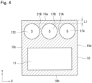
- the pillar member main body 10 has a substantially rectangular shape in a cross section perpendicular to the extending direction, and includes a surface 10a, a surface 10b facing the surface 10a, and surfaces 10c and 10d connecting the surface 10a and the surface 10b.
- the surface 10a is irradiated with sunlight.
- a hollow portion 20 and a cavity 11 are formed inside the pillar member main body 10. Each of the hollow portion 20 and the cavity 11 extends from the first end portion 15 toward the second end portion 16 and has both ends opened.
- the hollow portion 20 includes two first flow channels 17A and 17C through which the heating medium flows from the first end portion 15 toward the second end portion 16, and one second flow channel 17B through which the heating medium flows from the second end portion 16 toward the first end portion 15.
- the first flow channel 17A and the second flow channel 17B are arranged so as to be adjacent to each other with the partition wall 21A interposed therebetween, and the first flow channel 17C and the second flow channel 17B are arranged so as to be adjacent to each other with the partition wall 21B interposed therebetween.
- Each of the first flow channels 17A and 17C and the second flow channel 17B extends parallel to the extending direction of the pillar member main body 10.
- the first flow channel 17A is disposed on the surface 10d side with respect to the second flow channel 17B.
- the first flow channel 17A has a first opening 18A at the first end portion 15, and also has a second opening 19A at the second end portion 16.
- the second flow channel 17B has a first opening 18B at the first end portion 15, and also has a second opening 19B at the second end portion 16.
- the first flow channel 17C is disposed on the surface 10c side with respect to the second flow channel 17B.
- the first flow channel 17C has a first opening 18C at the first end portion 15, and also has a second opening 19C at the second end portion 16.
- first flow channels 17A and 17C and the second flow channel 17B are arranged on the surface 10a side with respect to the cavity 11, and are separated from the surface 10a by a distance L1.
- Each of the first flow channels 17A and 17C and the second flow channel 17B has a round shape in a cross section perpendicular to the extending direction of the pillar member main body 10 and has a constant cross-sectional area S.
- the cavity 11 is disposed on the surface 10b side with respect to the first flow channels 17A and 17C and the second flow channel 17B.
- the heating medium does not flow in the cavity 11, and is provided to reduce the weight of the pillar member main body 10. Therefore, the shape, position, and size of the cavity 11 are set so as to reduce the weight of the pillar member main body 10 while securing the cross-sectional performance of the pillar member main body 10 in the cross section perpendicular to the extending direction of the pillar member main body 10.
- the cavity 11 may not be provided.
- a lid portion 40A is fixed to the first end portion 15 of the pillar member main body 10 so as to close the hollow portion 20.
- a lid portion 40B is fixed to the second end portion 16 of the pillar member main body 10 so as to close the hollow portion 20.
- the lid portions 40A and 40B are formed by cutting an aluminum alloy.
- the lid portions 40A and 40B may be made of another metal material such as steel, aluminum, copper, a copper alloy, or silver.
- the thermal conductivity of the lid portions 40A and 40B is more preferably 200 w/m ⁇ K or more.
- the lid portion 40A is a rectangular prism member, and has a top surface 47a, a bottom surface 47b facing the top surface 47a, and side surfaces 47c, 47d, 47e, and 47f connecting the top surface 47a and the bottom surface 47b.
- the top surface 47a faces the pillar member main body 10.
- the side surfaces 47c, 47d, 47e, and 47f extend flush with the surfaces 10a, 10b, 10c, and 10d of the pillar member main body 10, respectively.
- the lid portion 40A has a recess 41A having a hollow structure and a base portion 44A having a solid structure.
- the recess 41A is provided so as to form an opening 49A on the top surface 47a.
- the base portion 44A is disposed on the bottom surface 47b side.
- the side surface 47f is provided with an inlet 42 through which the heating medium flows into the first flow channel 17A.
- the shape of the opening 49A of the recess 41A is the same as the outer shape of the cross-sectional shape perpendicular to the extending direction of the pillar member main body 10, that is, a substantially rectangular shape.
- the first end portion 15 side of the pillar member main body 10 is fitted to the recess 41A, and the first end portion 15 is in close contact with the contact surface 50A of the recess 41A.
- the lid portion 40A is fixed to the pillar member main body 10 by an arbitrary fixing method such as welding.
- connection flow channel 45A is a U-shaped flow channel having openings 51A and 51B at both ends.
- the opening 51A is aligned with the first opening 18C, and the opening 51B is aligned with the first opening 18B. Therefore, the connection flow channel 45A allows the second flow channel 17B and the first flow channel 17C to communicate with each other, and bends the flow direction of the heating medium by 180 degrees.
- the base portion 44A is provided with an inlet/outlet flow channel 46A.
- the inlet/outlet flow channel 46A is a flow channel having openings 51C and 51D at both ends.
- the opening 51C is aligned with the first opening 18A, and the opening 51D is aligned with the inlet 42. Therefore, the inlet/outlet flow channel 46A allows the first flow channel 17A and the inlet 42 to communicate with each other.
- the lid portion 40B is a rectangular parallelepiped member, and has a top surface 48a, a bottom surface 48b facing the top surface 48a, and side surfaces 48c, 48d, 48e, and 48f connecting the top surface 48a and the bottom surface 48b.
- the top surface 48a faces the pillar member main body 10.
- the side surfaces 48c, 48d, 48e, and 48f extend so as to be coplanar with the surfaces 10a, 10b, 10d, and 10c of the pillar member main body 10, respectively.
- the lid portion 40B has a recess 41B having a hollow structure and a base portion 44B having a solid structure.
- the recess 41B is provided so as to form an opening 49B on the top surface 48a.
- the base portion 44B is disposed on the bottom surface 48b side.
- the side surface 48f is provided with an outlet 43 through which the heating medium flows out from the first flow channel 17C.
- the shape of the opening 49B of the recess 41B is the same as the outer shape of the cross-sectional shape perpendicular to the extending direction of the pillar member main body 10, that is, a substantially rectangular shape.
- the second end portion 16 side of the pillar member main body 10 is fitted into the recess 41B, and the second end portion 16 is in close contact with the contact surface 50B of the recess 41B.
- the lid portion 40B is fixed to the pillar member main body 10 by an arbitrary fixing method such as welding.
- connection flow channel 45B is a U-shaped flow channel having openings 52A and 52B at both ends.
- the opening 52A is aligned with the second opening 19A, and the opening 52B is aligned with the second opening 19B. Therefore, the connection flow channel 45B allows the first flow channel 17A and the second flow channel 17B to communicate with each other, and bends the flow direction of the heating medium by 180 degrees.
- the base portion 44B is provided with an inlet/outlet flow channel 46B.
- the inlet/outlet flow channel 46B is a flow channel having openings 52C and 52D at both ends.
- the opening 52C is aligned with the second opening 19C, and the opening 52D is aligned with the outlet 43. Therefore, the inlet/outlet flow channel 46B allows the first flow channel 17C and outlet 43 to communicate with each other.
- the heating medium flowing in from the inlet 42 flows into the first flow channel 17A via the inlet/outlet flow channel 46A of the lid portion 40A, flows through the first flow channel 17A from the first end portion 15 toward the second end portion 16, and flows into the second flow channel 17B via the connection flow channel 45B of the lid portion 40B.
- the heating medium flowing into the second flow channel 17B flows from the second end portion 16 toward the first end portion 15, and flows into the first flow channel 17C via the connection flow channel 45A of the lid portion 40A.
- the heating medium flowing into the first flow channel 17C flows from the first end portion 15 toward the second end portion 16, and flows out to the outside of the pillar member 80A via the inlet/outlet flow channel 46B of the lid portion 40B and the outlet 53. That is, the heating medium flows in a meandering manner from the inlet 42 toward the outlet 43 via the first flow channels 17A and 17C, the second flow channel 17B, the connection flow channels 45A and 45B, and the inlet/outlet flow channels 46A and 46B.
- each of the pillar member 80B, the beam member 81, and the rafter members 82A and 82B has the same configuration as that of the pillar member 80A. That is, in each of the pillar member 80B, the beam member 81, and the rafter members 82A and 82B, the heating medium flowing in from the inlet 42 flows in a meandering manner toward the outlet 43.
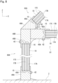
- the lid portion 40A in the pillar member 80A, the lid portion 40A is fixed to the ground 2 and extends in the Z direction (vertical direction). In the pillar member 80B, the lid portion 40B is fixed to the ground 2 and extends in the Z direction (vertical direction).
- the beam member 81 extends in the X direction (lateral direction) so as to connect the lid portion 40B of the pillar member 80A and the lid portion 40A of the pillar member 80B.
- the lid portion 40A of the beam member 81 is fixed to the lid portion 40B of the pillar member 80A, and the lid portion 40B of the beam member 81 is fixed to the lid portion 40A of the pillar member 80B by welding or the like.
- the rafter member 82A extends obliquely upward from the lid portion 40B of the pillar member 80A toward the center of the agricultural greenhouse 1.
- the rafter member 82B extends obliquely upward from the lid portion 40A of the pillar member 80B toward the center of the agricultural greenhouse 1.
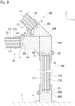
- the lid portion 40A of the rafter member 82A is fixed to the lid portion 40B of the pillar member 80A and the lid portion 40A of the beam member 81 by welding or the like.
- the lid portion 40B of the rafter member 82B is fixed to the lid portion 40A of the pillar member 80B and the lid portion 40B of the beam member 81 by welding or the like.
- the lid portion 40B of the rafter member 82A is connected to the lid portion 40A of the rafter member 82B.
- the lid portion 40B of the rafter member 82A is fixed to the lid portion 40A of the rafter member 82B by welding or the like.
- the tips of the respective lid portions 40A and 40B of the rafter members 82A and 82B each form an inclination angle, whereby the rafter members 82A and 82B each extend obliquely.
- the inlet 42 of the pillar member 80A is connected to the three-way valve 62 through the pipe 66e.
- the outlet 43 of the pillar member 80A is connected to the inlet 42 of the beam member 81 and the inlet 42 of the rafter member 82A via the external pipe 63a.
- the outlet 43 of the rafter member 82A is connected to the inlet 42 of the rafter member 82B via the external pipe 63b.
- the outlet 43 of the beam member 81 and the outlet 43 of the rafter member 82B are connected to the inlet 42 of the pillar member 80B via an external pipe 63c.
- the outlet 43 of the pillar member 80B is connected to the tank 58 via the pipe 66a.
- a flow of the heating medium in the agricultural greenhouse 1 will be described with reference to Fig. 2 .
- a neutral to weakly alkaline heating medium is used so that the aluminum alloy does not rust.
- a heating medium having a pH of 6 to 11 is used.
- the three-way valve 62 is controlled by the control unit 60, and the heating medium flows so as to circulate through the tank 58, the pillar members 80A and 80B, the beam member 81, and the rafter members 82A and 82B.
- the heating medium is pumped by the pump 59 from the tank 58 toward the inlet 42 of the pillar member 80A via the pipes 66b, 66d, and 66e and the three-way valve 62.
- the heating medium flowing into the pillar member 80A flows inside the pillar member 80A in a meandering manner and flows out from the outlet 43 of the pillar member 80A.
- the heating medium flowing out of the pillar member 80A flows into the beam member 81 and the rafter member 82A via the external pipe 63a.
- the heating medium flowing into the beam member 81 flows inside the beam member 81 in a meandering manner and flows out from the outlet 43 of the beam member 81.
- the heating medium flowing into the rafter member 82A flows in a meandering manner inside the rafter member 82A, flows out from the outlet 43 of the rafter member 82A, and flows into the rafter member 82B via the external pipe 63b.
- the heating medium flowing into the rafter member 82B flows in a meandering manner inside the rafter member 82B and flows out from the outlet 43 of the rafter member 82B.
- the heating medium flowing out from the rafter member 82B merges with the heating medium flowing out from the beam member 81 through the external pipe 63c, and flows into the pillar member 80B.
- the heating medium flowing into the pillar member 80B flows in a meandering manner inside the pillar member 80B, flows out from the outlet 43 of the pillar member 80B, and returns to the tank 58 via the pipe 66a. During this time, the heating medium is heated by each of the pillar members 80A and 80B, the beam member 81, and the rafter members 82A and 82B, and the temperature rises.
- the three-way valve 62 is controlled by the control unit 60, and the heating medium stored in the tank 58 flows so as to circulate through the radiator 61.
- the heating medium is pumped by the pump 59 from the tank 58 toward the radiator 61 via the pipes 66b, 66d, and 66f and the three-way valve 62.
- the heated heating medium exchanges heat with air in the cultivation space 64, and the temperature in the cultivation space 64 rises.
- the heating medium cooled by heat exchange in the radiator 61 returns to the tank 58 via the pipe 66c.
- the agricultural greenhouse 1 In the agricultural greenhouse 1 according to the present embodiment, sunlight incident on the surface 10a of the structural member main body 10 is converted into heat in the structural member main body 10, and the heat can be stored in the heating medium. That is, heat can be collected from sunlight in each of the pillar members 80A and 80B, the beam member 81, and the rafter members 82A and 82B.
- the agricultural greenhouse 1 is constructed such that the configuration other than the structural member and a transparent sheet is minimized in order to secure the light amount in the agricultural greenhouse 1. In other words, in the agricultural greenhouse 1, it is not desirable to provide a configuration other than the structural member and the transparent sheet because a decrease and unevenness in the solar radiation amount in the agricultural greenhouse occur.
- the hollow portion 20 includes the first flow channels 17A and 17C and the second flow channel 17B, the flow channel through which the heating medium flows becomes long, and the area where the structural member main body 10 and the heating medium are in contact with each other can be increased. Therefore, the heat of the structural member main body 10 heated by sunlight can be efficiently transferred to the heating medium.
- the heating medium flows in a meandering manner, it is possible to secure a large area where the structural member main body 10 and the heating medium are in contact with each other. In addition, the time during which the structural member main body 10 and the heating medium are in contact with each other can be long. Therefore, heat from sunlight can be efficiently stored in the heating medium.
- a flow channel in which the heating medium flows in a meandering manner can be formed. Therefore, processing for forming the meandering flow channel in the structural member main body 10 is not required, and the structural member main body 10 can be easily manufactured.
- the heating efficiency of the heating medium can be improved in a time period in which the sun altitude is low, for example at sunrise or sunset.
- the sun altitude In a time period in which the sun altitude is low, since sunlight is incident on the pillar members 80A and 80B at a small incident angle, the solar radiation amount may increase. Therefore, the amount of heat that the pillar members 80A and 80B receive from sunlight also increases, and the heating efficiency of the heating medium can be improved.
- the incident angle is an angle formed by a normal line of a surface irradiated with sunlight and a sunbeam.
- the heating efficiency of the heating medium can be improved in a time period in which the sun is located in the south during daytime and the sun altitude is high.
- the sun altitude In a time period in which the sun altitude is high, since sunlight is incident on the beam member 81 at a small incident angle, the solar radiation amount may increase. Therefore, the amount of heat that the beam member 81 receives from sunlight also increases, and the heating efficiency of the heating medium can be improved.
- the heating efficiency of the heating medium can be improved in a time period in which the sun is located in the south during the day and the sun altitude is high.
- the solar radiation amount may increase. Therefore, the amount of heat that the rafter members 82A and 82B receive from sunlight also increases, and the heating efficiency of the heating medium can be improved.
- the heating medium heated by sunlight exchanges heat with the radiator 61 to warm the air in the cultivation space 64, growth inhibition of plants due to temperature decrease at night is alleviated, and the growth rate of the plants can be improved.
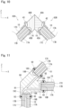
- the agricultural greenhouse 1 includes a connection lid portion 90.
- the connection lid portion 90 is formed as one component by integrally forming the lid portion 40B of the pillar member 80A, the lid portion 40A of the beam member 81, and the lid portion 40A of the rafter member 82A.
- a lid portion flow channel 91 is provided inside the connection lid portion 90.
- the lid portion flow channel 91 connects the second opening 19C of the pillar member 80A to the first opening 18A of the beam member 81 and the first opening 18A of the rafter member 82A. Since the external pipe 63a is not disposed, the agricultural greenhouse 1 can be easily assembled.
- each of the pillar member 80A, the beam member 81, and the rafter member 82A is fixed to the connection lid portion 90 by a screw 92. Therefore, the agricultural greenhouse 1 can be easily assembled.
- a configuration of an agricultural greenhouse 1 according to a second embodiment is different from that of the first embodiment in the following points.
- Other configurations of the second embodiment are similar to those of the first embodiment, and the same or similar elements as those of the first embodiment are denoted by the same reference numerals.
- the lid portions 40A and 40B are not provided with the connection flow channels 45A and 45B (shown in Fig. 5 ), and the liquid passage holes 22A and 22B are provided in the pillar member main body 10.
- the liquid passage hole 22A is provided on the first end portion 15 side of the partition wall 21B that separates the second flow channel 17B and the first flow channel 17C, and allows the second flow channel 17B and the first flow channel 17C to communicate with each other.
- the liquid passage hole 22B is provided on the second end portion 16 side of the partition wall 21A that separates the first flow channel 17A and the second flow channel 17B, and allows the first flow channel 17A and the second flow channel 17B to communicate with each other.
- the heating medium flowing into the pillar member main body 10 through the inlet 42 and the inlet/outlet flow channel 46A flows through the first flow channel 17A from the first end portion 15 toward the second end portion 16, and flows into the second flow channel 17B through the liquid passage hole 22B.
- the heating medium flowing into the second flow channel 17B flows from the second end portion 16 toward the first end portion 15, and flows into the first flow channel 17C via the liquid passage hole 22A.
- the heating medium flowing into the first flow channel 17C flows from the first end portion 15 toward the second end portion 16, and flows out to the outside of the pillar member main body 10 via the inlet/outlet flow channel 46B and the outlet 43.
- the heating medium flows in a meandering manner from the inlet 42 toward the outlet 43 via the first flow channels 17A and 17C, the second flow channel 17B, the liquid passage holes 22A and 22B, and the inlet/outlet flow channels 46A and 46B.
- the heating medium flows in a meandering manner, it is possible to secure a large area where the structural member main body 10 and the heating medium are in contact with each other.
- the time during which the structural member main body 10 and the heating medium are in contact with each other can be long. Therefore, heat from sunlight can be efficiently stored in the heating medium.
- a flow channel in which the heating medium flows in a meandering manner can be formed. Therefore, processing for forming the meandering flow channel is not required for the lid portions 40A and 40B, and the lid portions 40A and 40B can be easily manufactured.
- a configuration of an agricultural greenhouse 1 according to a third embodiment is different from that of the first embodiment in the following points.
- Other configurations of the third embodiment are similar to those of the first embodiment, and the same or similar elements as those of the first embodiment are denoted by the same reference numerals.
- the pillar member main body 10 is provided with a rib 30 protruding toward the first flow channel 17A.
- the rib 30 extends from the first end portion 15 (shown in Fig. 3 ) to the second end portion 16 (shown in Fig. 3 ) along the extending direction of the pillar member main body 10.
- ribs 30 are provided in each of the second flow channel 17B and the first flow channel 17C.
- the rib 30 is formed integrally with the pillar member main body 10 by extrusion or casting.
- the rib 30 is provided, the area where the structural member main body 10 and the heating medium are in contact with each other is increased. Therefore, the heat from the sunlight with which the structural member main body 10 is irradiated and is converted can be efficiently transferred to the heating medium and stored.
- the structural member main body 10 is an extrusion product or a cast product, a structure having such a rib 30 can also be easily formed.
- a configuration of an agricultural greenhouse 1 according to a fourth embodiment is different from that of the first embodiment in the following points.
- Other configurations of the fourth embodiment are similar to those of the first embodiment, and the same or similar elements as those of the first embodiment are denoted by the same reference numerals.
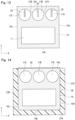
- the surface 10a of the pillar member main body 10 is coated with a black film 36.
- the black film 36 is, for example, a high emissivity film obtained by electrolytically treating an aluminum alloy, and absorbs light of almost all wavelengths of sunlight.
- the heat insulating materials 37A, 37B, and 37C are disposed on the outer surface 38 excluding the surface 10a.
- the heat insulating material 37A is disposed so as to be in contact with the surface 10b
- the heat insulating material 37B is disposed so as to be in contact with the surface 10c
- the heat insulating material 37C is disposed so as to be in contact with the surface 10d.
- the heat collecting member in the fourth embodiment since the emissivity on the surface 10a can be improved, the heating efficiency of the heating medium by sunlight can be improved.
- the heat insulating materials 37A to 37C are provided, it is possible to suppress or prevent heat of the heated heating medium or the structural member main body 10 from being radiated to the atmosphere. The heating efficiency of the heating medium can thus be improved.
- a configuration of the agricultural greenhouse 1 according to a fifth embodiment is different from that of the first embodiment in the following points.
- Other configurations of the fifth embodiment are similar to those of the first embodiment, and the same or similar elements as those of the first embodiment are denoted by the same reference numerals.
- the pillar member 80A includes a buried portion 12A extended beyond the ground 2 and is buried in the ground 4.
- the pillar member 80B includes a buried portion 12B extended beyond the ground 2 and is buried in the ground 4.
- the length L2 of the buried portions 12A and 12B is arbitrary, but is preferably 10 m or more.
- the inlet 42 of the pillar member 80A is not provided in the lid portion 40A, but is provided above the ground 2 of the pillar member main body 10.
- the lid portion 40A does not have the inlet/outlet flow channel 46A (shown in Fig. 5 ). That is, the first opening 18A of the first flow channel 17A is sealed by the lid portion 40A. Therefore, when the heating medium circulates in the agricultural greenhouse 1, the heating medium is accumulated between the first end portion 15 of the first flow channel 17A of the pillar member 80A and the inlet 42, and the heating medium does not flow.
- the heating medium flowing into the pillar member 80A flows through the first flow channel 17A from the inlet 42 toward the second end portion 16.
- the pillar member 80B has a similar configuration. That is, the heating medium is accumulated between the second end portion 16 of the first flow channel 17C of the pillar member 80B and the outlet 43, and the heating medium does not flow. The heating medium flowing into the pillar member 80B flows through the first flow channel 17C from the first end portion 15 toward the outlet 43.
- the agricultural greenhouse 1 of the fifth embodiment it is possible to use the heating medium using the underground heat obtained through the buried portions 12A and 12B in addition to the heat from the sunlight.
- the underground temperature is higher than the air temperature, the inside of the agricultural greenhouse 1 can be warmed using the underground heat.
- a configuration of an agricultural greenhouse 1 according to a sixth embodiment is different from that of the first embodiment in the following points.
- Other configurations of the sixth embodiment are similar to those of the first embodiment, and the same or similar elements as those of the first embodiment are denoted by the same reference numerals.
- the pillar member main body 10 has the same structure as that of the first embodiment (see Figs. 3 and 4 ), while the pair of lid portions 40A and 40B has a structure different from that of the first embodiment. Therefore, the flow channel structure of the heating medium in the pillar member 80A is also different from that of the first embodiment.
- the base portion 44A of the lid portion 40A is provided with a common flow channel 45A and an inlet/outlet flow channel 46A.
- the common flow channel 45A is constituted by a groove recessed from the contact surface 50A of the recess 41A toward the bottom surface 47b.
- the opening 51D of the inlet/outlet flow channel 46A is aligned with the inlet 42 as in the first embodiment, while the opening 51C is open to the common flow channel 45A.
- the lid portion 40B is configured similarly to the lid portion 40A.
- the base portion 44B of the lid portion 40B is provided with a common flow channel 45B and an inlet/outlet flow channel 46B.
- the common flow channel 45B includes a groove recessed from the contact surface 50B of the recess 41B toward the bottom surface 48b.
- the opening 52D of the inlet/outlet flow channel 46B is aligned with the outlet 43 as in the first embodiment, while the opening 52C is open to the common flow channel 45B.
- the first end portion 15 of the pillar member main body 10 is fitted into the recess 41A of the lid portion 40A and comes into contact with the contact surface 50A
- the second end portion 16 of the pillar member main body 10 is fitted into the recess 41B of the lid portion 40B and comes into contact with the contact surface 50B
- the hollow portion 20 of the pillar member main body 10 is constituted by three elongated holes arranged adjacent to each other with partition walls 21A and 21B interposed therebetween, and each of the elongated holes has first openings 18D, 18E, and 18F opened at the first end portion 15 and second openings 19D, 19E, and 19F opened at the second end portion 16. All of the first openings 18D, 18E, and 18F communicate with the common flow channel 45A of the lid portion 40A. All of the second openings 19D, 19E, and 19F communicate with the common flow channel 45B of the lid portion 40B.
- the heating medium flowing in from the inlet 42 flows into the common flow channel 45A via the inlet/outlet flow channel 45A of the lid portion 40A.
- the heating medium flows into the three elongated holes from the common flow channel 44A through the three first openings 18D, 18E, and 18F.
- the heating medium flows from the first end portion 15 toward the second end portion 16 in each of the three elongated holes. That is, all of these elongated holes serve as the first flow channels 17D, 17E, and 17F through which the heating medium flows from the first end portion 15 toward the second end portion 16.
- the heating medium in each of the first flow channels 17D, 17E, and 17F joins at the common flow channel 45B of the lid portion 40B via the second openings 19D, 19E, and 19F.
- the heating medium flows from the common flow channel 45B toward the outlet 42 via the inlet/outlet flow channel 46B and flows out from the outlet 42.
- the pillar member 40 does not include the second flow channel (for example, the flow channel 17B illustrated in Fig. 5 ) through which the heating medium flows from the second end portion 16 where the outlet 43 is disposed toward the first end portion 15 where the inlet 42 is disposed.
- the hollow portion 20 of the pillar member main body 10 is a plurality of first flow channels 17D, 17E, and 17F connected in parallel to the common flow channels 44A and 45B. The heating medium is delivered into the first flow channels 17D, 17E, and 17F and flows in a one-way manner from the first end portion 15 toward the second end portion 16.
- the beam member 81 and the rafter members 82A and 82B also have first flow channels 17D, 17E, and 17F through which the heating medium flows in a one-way manner from the first end portion 15 toward the second end portion 16.
- the present embodiment it is possible to provide a building that collects heat from sunlight while suppressing an increase in a shadow generation range which is also a cause of a decrease and unevenness in the solar radiation amount in an agricultural greenhouse.
- the plurality of first flow channels are connected in parallel and the heating medium flows in a one-way manner, it is easy to ensure the flow rate of the heating medium.
- the temperature in the greenhouse can be lowered by the heating medium when the temperature in the greenhouse rises excessively, and the heating medium can also be used as an auxiliary device for cooling equipment.
- the residence time of the heating medium is shortened, the load of the pump 59 can be reduced.
- a configuration of an agricultural greenhouse 1 according to a seventh embodiment is different from that of the first embodiment in the following points.
- Other configurations of the seventh embodiment are similar to those of the first embodiment, and the same or similar elements as those of the first embodiment are denoted by the same reference numerals.
- the difference of the present embodiment from the sixth embodiment is the same as the difference of the second embodiment from the first embodiment.
- the lid portions 40A and 40B are not provided with the common flow channels 45A and 45B (see Fig. 17 ), and the pillar member main body 10 is provided with the recesses 23A and 23B.
- the recess 23A is concave from the end surface of the first end portion 15 toward the second end portion 16.
- the first openings 18D, 18E, and 18F are opened in the bottom surface 24A of the recess 23A. All of the first flow channels 17D, 17E, and 17F communicate with the recess 23A on the first end portion 15 side.
- the recess 23B is concave from the end surface of the second end portion 16 toward the first end portion 15.
- the second openings 19D, 19E, and 19F are opened in the bottom surface 24B of the recess 23B. All of the first flow channels 17D, 17E, and 17F communicate with the recess 23B on the second end portion 16 side.
- the inlet/outlet flow channel 46A of the lid portion 40A allows the inlet 42 to communicate with the recess 23A.
- the inlet/outlet flow channel 46B of the lid portion 40B allows the recess 23B to communicate with the outlet 43.
- the recesses 23A and 23B perform functions equivalent to those of the common flow channels 45A and 45B in the sixth embodiment. That is, the heating medium flows into the recess 23A from the inlet 42 via the inlet/outlet flow channel 46A, is delivered into the plurality of first flow channels 17D, 17E, and 17F from the recess 23A, flows through the first flow channels 17D, 17E, and 17F, joins at the recess 23B, and flows toward the outlet 43 via the inlet/outlet flow channel 46. As a result, the same effects as those of the sixth embodiment can be obtained.
- the structural member main body has a rectangular cross section, but the cross-sectional shape of the structural member main body is not particularly limited.
- the pillar member main body 10 may have a C-shaped or U-shaped cross section.
- the pillar member main body 10 may have an H-shaped cross section.
- the material is not limited to the aluminum alloy, and may be another metal material such as steel, aluminum, copper, a copper alloy, or silver.
- the main bodies of other structural members (for example, the beam member and the rafter member) can be modified in the same manner.
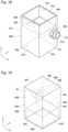
- the C-shaped pillar member main body 10 includes a web 10W and a pair of flanges 10F and 10F extending perpendicularly from both end portions of the web 10W, and has a C-shaped cross section as a whole.
- the hollow portion 20 (a plurality of elongated holes) is provided in at least one of the three portions of the web 10W and the pair of flanges 10F.
- the hollow portion 20 may be provided in all of the three portions as illustrated in Fig. 24A , or may be provided only in the web 10W as illustrated in Fig. 24B .
- the number of elongated holes provided in each of the three portions is not particularly limited. In the case of the meandering type as in the first embodiment, the total number of elongated holes may be an odd number of three or more, and in the case of the one-way type as in the sixth embodiment, the total number of elongated holes may be plural.
- the H-shaped pillar member main body 10 includes a web 10W and a pair of flanges 10F extending perpendicularly from both end portions of the web 10W, and has a H-shaped cross section as a whole.
- the portion where the hollow portion 20 is provided and the number of elongated holes constituting the hollow portion 20 are the same as those of the above-described C-shaped pillar member main body 10.
- the elongated holes may be arranged side by side in the plate thickness direction of the web 10W.
Landscapes
- Engineering & Computer Science (AREA)
- Life Sciences & Earth Sciences (AREA)
- Physics & Mathematics (AREA)
- Sustainable Energy (AREA)
- Sustainable Development (AREA)
- Combustion & Propulsion (AREA)
- Thermal Sciences (AREA)
- Chemical & Material Sciences (AREA)
- Mechanical Engineering (AREA)
- General Engineering & Computer Science (AREA)
- Architecture (AREA)
- Environmental Sciences (AREA)
- Soil Sciences (AREA)
- Structural Engineering (AREA)
- Civil Engineering (AREA)
- Electromagnetism (AREA)
- Acoustics & Sound (AREA)
- Greenhouses (AREA)
Abstract
Description
- The present invention relates to a building.
- A building installed with a heat collecting member that stores heat obtained by sunlight in a heating medium is known.
Patent Literature 1 discloses an agricultural greenhouse installed with a heat collecting member. During the day, the heating medium heated by irradiating the heat collecting member with sunlight circulates in the agricultural greenhouse at night to warm the air in the agricultural greenhouse. - Patent Document 1:
JP-A-2019-122271 - In the agricultural greenhouse disclosed in
Patent Document 1, since the panel-type heat collecting member is disposed in the upper space in the agricultural greenhouse, a decrease and unevenness in the solar radiation amount in the agricultural greenhouse occur. Photosynthesis of crops cultivated in the agricultural greenhouse is thus suppressed due to the decrease and unevenness in the solar radiation amount, and there is a risk of affecting the growth and yield of the crops. - The present invention provides a building that collects heat from sunlight while suppressing an increase in a shadow generation range which is also a cause of a decrease and unevenness in the solar radiation amount in an agricultural greenhouse.
- The present invention provides a building including at least one structural member, the structural member including a structural member main body that is formed by extrusion or casting of a metal, includes a light-receiving surface irradiated with sunlight, and is internally formed with a hollow portion extending from a first end portion toward a second end portion, a pair of lid portions that are respectively disposed at the first end portion and the second end portion, and close the hollow portion, an inlet that is provided in any one of the pair of lid portions and through which a heating medium flows into the hollow portion, and an outlet that is provided in any one of the pair of lid portions and through which the heating medium flows out from the hollow portion.
- According to the building of the present invention, sunlight incident on the light-receiving surface of the structural member main body is converted into heat in the structural member main body, and the heat can be stored in the heating medium. That is, heat can be collected from sunlight in the structural member. Here, the structural member is a member necessary for a building to be constructed in a certain structure and for the structure to be maintained. For example, the agricultural greenhouse is constructed such that the configuration other than the structural member and a transparent sheet is minimized in order to secure the light amount in the agricultural greenhouse. In other words, in the agricultural greenhouse, it is not desirable to provide a configuration other than the structural member and the transparent sheet because the solar radiation amount is reduced. In the present invention, since heat can be collected from sunlight in the structural member, installation of other heat collecting members can be suppressed, and a decrease in the solar radiation amount in the agricultural greenhouse can be suppressed.
- The hollow portion may include a first flow channel through which the heating medium flows from the first end portion toward the second end portion, and a second flow channel that is disposed so as to be adjacent to the first flow channel with a partition wall interposed between the first flow channel and the second flow channel and through which the heating medium flows from the second end portion toward the first end portion.
- According to the above configuration, since the hollow portion includes two flow channels, the flow channel through which the heating medium flows becomes long, and the area where the structural member main body and the heating medium are in contact with each other can be increased. Therefore, the heat of the structural member main body heated by sunlight can be efficiently transferred to the heating medium.
- Each of the pair of lid portions may be provided with a connection flow channel connecting the first flow channel and the second flow channel such that the heating medium flows in a meandering manner from the inlet toward the outlet.
- According to the above configuration, since the heating medium flows in a meandering manner, it is possible to secure a large area where the structural member main body and the heating medium are in contact with each other. In addition, the time during which the structural member main body and the heating medium are in contact with each other can be long. Therefore, heat from sunlight can be efficiently stored in the heating medium. In addition, by processing the lid portion and providing the connection flow channel, a flow channel in which the heating medium flows in a meandering manner can be formed. Therefore, processing for forming the meandering flow channel in the structural member main body is not required, and the structural member main body can be easily manufactured.
- The partition wall may be provided with a liquid passage hole connecting the first flow channel and the second flow channel such that the heating medium flows in a meandering manner from the inlet toward the outlet.
- According to the above configuration, since the heating medium flows in a meandering manner, it is possible to secure a large area where the structural member main body and the heating medium are in contact with each other. In addition, the time during which the structural member main body and the heating medium are in contact with each other can be long. Therefore, heat from sunlight can be efficiently stored in the heating medium. In addition, by processing the structural member main body and providing the liquid passage hole, a flow channel in which the heating medium flows in a meandering manner can be formed. Therefore, processing for forming the meandering flow channel is not required for the lid portion, and the lid portion can be easily manufactured.
- The hollow portion may include a plurality of first flow channels disposed so as to be adjacent to each other with a partition wall interposed between the plurality of first flow channels and through which the heating medium flows from the first end portion toward the second end portion.
- According to the above configuration, since the heating medium flows in one direction through the plurality of first flow channels, a flow rate can be ensured.
- Each of the pair of lid portions may be provided with a common flow channel communicating with each of opening ends of the plurality of first flow channels such that the heating medium is delivered from the inlet to the plurality of first flow channels, and the heating medium merges from the plurality of first flow channels and flows toward the outlet.
- According to the above configuration, it is possible to easily realize a structure for securing the flow rate of the heating medium using the plurality of first flow channels.
- The structural member main body may include a recess provided at the first end portion and the second end portion and allowing end portions of the plurality of first flow channels to communicate with each other, and each of the pair of lid portions may be provided with an inlet/outlet flow channel allowing the inlet or the outlet to communicate with the recess.
- According to the above configuration, it is possible to easily realize a structure for securing the flow rate of the heating medium using the plurality of first flow channels.
- The structural member main body may be provided with a rib along a direction in which the hollow portion extends.
- According to the above configuration, since the rib is provided, an area where the structural member main body and the heating medium are in contact with each other is increased. Therefore, the heat from the sunlight with which the structural member main body is irradiated and is converted can be efficiently transferred to the heating medium and stored.
- The light-receiving surface may be coated with a black film.
- According to the above configuration, since the emissivity on the light-receiving surface can be improved, the heating efficiency of the heating medium by sunlight can be improved.
- A heat insulating material may be disposed on an outer surface of the structural member except the light-receiving surface.
- According to the above configuration, it is possible to suppress or prevent the heat of the heated heating medium or structural member from being released to the atmosphere. The heating efficiency of the heating medium can thus be improved.
- The structural member may be a pillar member fixed to the ground and extending in the vertical direction.
- According to the above configuration, the heating efficiency of the heating medium can be improved in a time period in which the sun altitude is low, for example at sunrise or sunset. In a time period in which the sun altitude is low, since sunlight is incident on the pillar member at a small incident angle, the solar radiation amount may increase. Therefore, the amount of heat that the pillar member receives from sunlight also increases, and the heating efficiency of the heating medium can be improved.
- The structural member may include a buried portion extended beyond the ground and buried in the ground.
- According to the above configuration, in addition to heat from sunlight, ground heat can be used for heating the heating medium.
- The structural member may be a beam member extending in the lateral direction.
- According to the above configuration, the heating efficiency of the heating medium can be improved in a time period in which the sun is located in the south during daytime and the sun altitude is high. In a time period in which the sun altitude is high, since sunlight is incident on the beam member at a small incident angle, the solar radiation amount may increase. Therefore, the amount of heat that the beam member receives from sunlight also increases, and the heating efficiency of the heating medium can be improved.
- The structural member may be a pair of rafter members extending in oblique directions and connected to each other.
- According to the above configuration, the heating efficiency of the heating medium can be improved in a time period in which the sun is located in the south during daytime and the sun altitude is high. In a time period in which the sun altitude is high, since sunlight is incident on the rafter member at a small incident angle, the solar radiation amount may increase. Therefore, the amount of heat that the rafter member receives from sunlight also increases, and the heating efficiency of the heating medium can be improved.
- The building according to the present invention can collect heat from sunlight while suppressing an increase in a shadow generation range which is also a cause of a decrease and unevenness in the solar radiation amount in an agricultural greenhouse.
-
-
Fig. 1 is a schematic view of an agricultural greenhouse according to a first embodiment of the present invention. -
Fig. 2 is a schematic configuration diagram of the agricultural greenhouse according to the first embodiment of the present invention. -
Fig. 3 is an exploded perspective view of a structural member according to the first embodiment of the present invention. -
Fig. 4 is a cross-sectional view taken along a line IV-IV inFig. 3 . -
Fig. 5 is a cross-sectional view taken along a line V-V inFig. 3 . -
Fig. 6 is a perspective view of a lid portion according to the first embodiment of the present invention. -
Fig. 7 is a perspective view of the lid portion according to the first embodiment of the present invention. -
Fig. 8 is a partial cross-sectional view taken along a line VIII-VIII inFig. 1 . -
Fig. 9 is a partial cross-sectional view similar toFig. 8 . -
Fig. 10 is a partial cross-sectional view similar toFig. 8 . -
Fig. 11 is a view showing a modification of the first embodiment of the present invention. -
Fig. 12 is a cross-sectional view similar toFig. 5 of an agricultural greenhouse according to a second embodiment of the present invention. -
Fig. 13 is a cross-sectional view of an agricultural greenhouse according to a third embodiment of the present invention, similar toFig. 4 . -
Fig. 14 is a cross-sectional view of an agricultural greenhouse according to a fourth embodiment of the present invention, similar toFig. 4 . -
Fig. 15 is a schematic configuration diagram of an agricultural greenhouse according to a fifth embodiment of the present invention. -
Fig. 16 is a partial cross-sectional view similar toFig. 8 of the agricultural greenhouse according to the fifth embodiment of the present invention. -
Fig. 17 is a partial cross-sectional view similar toFig. 5 of the agricultural greenhouse according to a sixth embodiment of the present invention. -
Fig. 18 is a perspective view of the lid portion similar toFig. 6 of the agricultural greenhouse according to the sixth embodiment of the present invention. -
Fig. 19 is a perspective view of the lid portion similar toFig. 7 of the agricultural greenhouse according to the sixth embodiment of the present invention. -
Fig. 20 is a partial cross-sectional view similar toFig. 8 of the agricultural greenhouse according to the sixth embodiment of the present invention. -
Fig. 21 is a partial cross-sectional view similar toFig. 9 of the agricultural greenhouse according to the sixth embodiment of the present invention. -
Fig. 22 is a partial cross-sectional view similar toFig. 10 of the agricultural greenhouse according to the sixth embodiment of the present invention. -
Fig. 23 is a partial cross-sectional view similar toFig. 12 of the agricultural greenhouse according to a seventh embodiment of the present invention. -
Fig. 24A is a cross-sectional view of the structural member similar toFig. 4 according to a first modification of the present invention. -
Fig. 24B is a cross-sectional view of the structural member similar toFig. 4 according to a second modification of the present invention. -
Fig. 25A is a cross-sectional view of a structural member similar toFig. 4 according to a third modification of the present invention. -
Fig. 25B is a cross-sectional view of a structural member similar toFig. 4 according to a fourth modification of the present invention. - Referring to
Fig. 1 , an agricultural greenhouse (building) 1 according to the present embodiment is a building installed with respect to theground 2 so that an installation region is rectangular, and includes pillar members (structural members) 80A and 80B, a beam member (structural member) 81, a pair of rafter members (structural members) 82A and 82B, and a translucent vinyl sheet or a glass plate (not shown) covering them. - In the present embodiment, each of the
pillar members beam member 81, and therafter members agricultural greenhouse 1, and has rigidity capable of withstanding the weight of theagricultural greenhouse 1, a load applied to theagricultural greenhouse 1 from the outside such as wind, and the like. - In addition, in the present embodiment, the
pillar members beam member 81, and therafter members pillar members beam member 81, and therafter members surface 10a faces the south. As will be described in detail later, by collecting heat of sunlight on thesurface 10a, the heating medium flowing inside each of thepillar members beam member 81, and therafter members - In the following description, a shorter direction of the
agricultural greenhouse 1 parallel to theground 2 is defined as an X direction, a longitudinal direction of theagricultural greenhouse 1 parallel to theground 2 is defined as a Y direction, and a height direction of theagricultural greenhouse 1 perpendicular to theground 2 is defined as a Z direction. - The
agricultural greenhouse 1 is a building elongated in the Y direction in plan view. Thepillar members beam member 81, and therafter members member 83 extending in the Y direction. - The
agricultural greenhouse 1 includes acultivation space 64 and anupper space 65. Thecultivation space 64 is a space below thebeam member 81, and theupper space 65 is a space above thebeam member 81. - Referring to
Fig. 2 , theagricultural greenhouse 1 includes atank 58, apump 59, acontrol unit 60, a three-way valve 62, and aradiator 61. In the present embodiment, one set of thepillar members beam member 81, and therafter members tank 58, thepump 59, thecontrol unit 60, the three-way valve 62, and theradiator 61. A set of thetank 58, thepump 59, thecontrol unit 60, the three-way valve 62, and theradiator 61 may be provided in the entireagricultural greenhouse 1. - The
tank 58 is connected to thepillar member 80B via apipe 66a, connected to thepump 59 via apipe 66b, and connected to theradiator 61 via apipe 66c. Thepump 59 is connected to the three-way valve 62 via apipe 66d. The three-way valve 62 is connected to thepillar member 80A via thepipe 66e, and is connected to theradiator 61 via apipe 66f. - The three-
way valve 62 is controlled by thecontrol unit 60 to switch the flow of the heating medium flowing from thepipe 66d to thepipe 66e or thepipe 66f. - The heating medium is stored in the
tank 58. The heating medium is pumped by thepump 59 and sent to thepillar member 80A or theradiator 61 via the three-way valve 62. Specifically, the heating medium is sent to thepillar member 80A as the heat collecting portion during the day, and is sent to theradiator 61 at night. - As will be described in detail later, the heating medium sent to the
pillar member 80A returns to thetank 58 via thebeam member 81, therafter members pillar member 80B. Meanwhile, the heating medium is warmed by sunlight. The heating medium sent to theradiator 61 returns to thetank 58 via thepipe 66c. - In the
radiator 61, the heated heating medium flows and exchanges heat with the air in theagricultural greenhouse 1. Therefore, the air in theagricultural greenhouse 1 is warmed, and the heating medium is cooled. As theradiator 61, a known radiator that exchanges heat with a heating medium flowing inside can be used, and for example, a tube crawling on the ground in theagricultural greenhouse 1 can be used. - In the present embodiment, the
radiator 61 is disposed in thecultivation space 64. Thecultivation space 64 and theupper space 65 may be partitioned by a curtain (not illustrated). The curtain prevents heat transfer between thecultivation space 64 and theupper space 65, thereby improving heat retaining property of thecultivation space 64. - The configuration of the
pillar member 80A will be described with reference toFig. 3 . In the present embodiment, since thepillar members beam member 81, and therafter members pillar member 80B, thebeam member 81, and therafter members - The
pillar member 80A includes a pillar member main body (structural member main body) 10 and a pair oflid portions - The pillar member
main body 10 is an elongated member formed by extrusion or casting of a metal and extending from thefirst end portion 15 toward thesecond end portion 16 at an arbitrary length. In the present embodiment, the pillar membermain body 10 is formed of an aluminum alloy. The pillar membermain body 10 may be another metal material, for example, steel, aluminum, copper, a copper alloy, silver, or the like. The thermal conductivity of the pillar membermain body 10 is more preferably 200 w/m·K or more. - Referring to
Fig. 4 , the pillar membermain body 10 has a substantially rectangular shape in a cross section perpendicular to the extending direction, and includes asurface 10a, asurface 10b facing thesurface 10a, and surfaces 10c and 10d connecting thesurface 10a and thesurface 10b. As described above, in the present embodiment, thesurface 10a is irradiated with sunlight. - A
hollow portion 20 and acavity 11 are formed inside the pillar membermain body 10. Each of thehollow portion 20 and thecavity 11 extends from thefirst end portion 15 toward thesecond end portion 16 and has both ends opened. - Referring also to
Fig. 5 , thehollow portion 20 includes twofirst flow channels first end portion 15 toward thesecond end portion 16, and onesecond flow channel 17B through which the heating medium flows from thesecond end portion 16 toward thefirst end portion 15. Thefirst flow channel 17A and thesecond flow channel 17B are arranged so as to be adjacent to each other with thepartition wall 21A interposed therebetween, and thefirst flow channel 17C and thesecond flow channel 17B are arranged so as to be adjacent to each other with thepartition wall 21B interposed therebetween. Each of thefirst flow channels second flow channel 17B extends parallel to the extending direction of the pillar membermain body 10. - The
first flow channel 17A is disposed on thesurface 10d side with respect to thesecond flow channel 17B. Thefirst flow channel 17A has afirst opening 18A at thefirst end portion 15, and also has asecond opening 19A at thesecond end portion 16. - The
second flow channel 17B has afirst opening 18B at thefirst end portion 15, and also has asecond opening 19B at thesecond end portion 16. - The
first flow channel 17C is disposed on thesurface 10c side with respect to thesecond flow channel 17B. Thefirst flow channel 17C has afirst opening 18C at thefirst end portion 15, and also has asecond opening 19C at thesecond end portion 16. - Referring to
Fig. 4 , in the present embodiment, thefirst flow channels second flow channel 17B are arranged on thesurface 10a side with respect to thecavity 11, and are separated from thesurface 10a by a distance L1. Each of thefirst flow channels second flow channel 17B has a round shape in a cross section perpendicular to the extending direction of the pillar membermain body 10 and has a constant cross-sectional area S. - The
cavity 11 is disposed on thesurface 10b side with respect to thefirst flow channels second flow channel 17B. In the present embodiment, the heating medium does not flow in thecavity 11, and is provided to reduce the weight of the pillar membermain body 10. Therefore, the shape, position, and size of thecavity 11 are set so as to reduce the weight of the pillar membermain body 10 while securing the cross-sectional performance of the pillar membermain body 10 in the cross section perpendicular to the extending direction of the pillar membermain body 10. Thecavity 11 may not be provided. - Referring to
Figs. 3 and5 , alid portion 40A is fixed to thefirst end portion 15 of the pillar membermain body 10 so as to close thehollow portion 20. Alid portion 40B is fixed to thesecond end portion 16 of the pillar membermain body 10 so as to close thehollow portion 20. - In the present embodiment, the
lid portions lid portions lid portions - Referring also to
Fig. 6 , thelid portion 40A is a rectangular prism member, and has atop surface 47a, abottom surface 47b facing thetop surface 47a, andside surfaces top surface 47a and thebottom surface 47b. Thetop surface 47a faces the pillar membermain body 10. The side surfaces 47c, 47d, 47e, and 47f extend flush with thesurfaces main body 10, respectively. - The
lid portion 40A has arecess 41A having a hollow structure and abase portion 44A having a solid structure. Therecess 41A is provided so as to form anopening 49A on thetop surface 47a. Thebase portion 44A is disposed on thebottom surface 47b side. - The
side surface 47f is provided with aninlet 42 through which the heating medium flows into thefirst flow channel 17A. - The shape of the
opening 49A of therecess 41A is the same as the outer shape of the cross-sectional shape perpendicular to the extending direction of the pillar membermain body 10, that is, a substantially rectangular shape. Thefirst end portion 15 side of the pillar membermain body 10 is fitted to therecess 41A, and thefirst end portion 15 is in close contact with thecontact surface 50A of therecess 41A. Thelid portion 40A is fixed to the pillar membermain body 10 by an arbitrary fixing method such as welding. - The
base portion 44A is provided with aconnection flow channel 45A. Theconnection flow channel 45A is a U-shaped flowchannel having openings opening 51A is aligned with thefirst opening 18C, and theopening 51B is aligned with thefirst opening 18B. Therefore, theconnection flow channel 45A allows thesecond flow channel 17B and thefirst flow channel 17C to communicate with each other, and bends the flow direction of the heating medium by 180 degrees. - The
base portion 44A is provided with an inlet/outlet flow channel 46A. The inlet/outlet flow channel 46A is a flowchannel having openings opening 51C is aligned with thefirst opening 18A, and theopening 51D is aligned with theinlet 42. Therefore, the inlet/outlet flow channel 46A allows thefirst flow channel 17A and theinlet 42 to communicate with each other. - Referring to
Figs. 3 ,5 , and7 , thelid portion 40B is a rectangular parallelepiped member, and has atop surface 48a, abottom surface 48b facing thetop surface 48a, andside surfaces top surface 48a and thebottom surface 48b. Thetop surface 48a faces the pillar membermain body 10. The side surfaces 48c, 48d, 48e, and 48f extend so as to be coplanar with thesurfaces main body 10, respectively. - The
lid portion 40B has arecess 41B having a hollow structure and abase portion 44B having a solid structure. Therecess 41B is provided so as to form anopening 49B on thetop surface 48a. Thebase portion 44B is disposed on thebottom surface 48b side. - The
side surface 48f is provided with anoutlet 43 through which the heating medium flows out from thefirst flow channel 17C. - The shape of the
opening 49B of therecess 41B is the same as the outer shape of the cross-sectional shape perpendicular to the extending direction of the pillar membermain body 10, that is, a substantially rectangular shape. Thesecond end portion 16 side of the pillar membermain body 10 is fitted into therecess 41B, and thesecond end portion 16 is in close contact with thecontact surface 50B of therecess 41B. Thelid portion 40B is fixed to the pillar membermain body 10 by an arbitrary fixing method such as welding. - The
base portion 44B is provided with aconnection flow channel 45B. Theconnection flow channel 45B is a U-shaped flowchannel having openings opening 52A is aligned with thesecond opening 19A, and theopening 52B is aligned with thesecond opening 19B. Therefore, theconnection flow channel 45B allows thefirst flow channel 17A and thesecond flow channel 17B to communicate with each other, and bends the flow direction of the heating medium by 180 degrees. - The
base portion 44B is provided with an inlet/outlet flow channel 46B. The inlet/outlet flow channel 46B is a flowchannel having openings opening 52C is aligned with thesecond opening 19C, and theopening 52D is aligned with theoutlet 43. Therefore, the inlet/outlet flow channel 46B allows thefirst flow channel 17C andoutlet 43 to communicate with each other. - Referring to
Fig. 5 , the heating medium flowing in from theinlet 42 flows into thefirst flow channel 17A via the inlet/outlet flow channel 46A of thelid portion 40A, flows through thefirst flow channel 17A from thefirst end portion 15 toward thesecond end portion 16, and flows into thesecond flow channel 17B via theconnection flow channel 45B of thelid portion 40B. The heating medium flowing into thesecond flow channel 17B flows from thesecond end portion 16 toward thefirst end portion 15, and flows into thefirst flow channel 17C via theconnection flow channel 45A of thelid portion 40A. The heating medium flowing into thefirst flow channel 17C flows from thefirst end portion 15 toward thesecond end portion 16, and flows out to the outside of thepillar member 80A via the inlet/outlet flow channel 46B of thelid portion 40B and the outlet 53. That is, the heating medium flows in a meandering manner from theinlet 42 toward theoutlet 43 via thefirst flow channels second flow channel 17B, theconnection flow channels outlet flow channels - As described above, each of the
pillar member 80B, thebeam member 81, and therafter members pillar member 80A. That is, in each of thepillar member 80B, thebeam member 81, and therafter members inlet 42 flows in a meandering manner toward theoutlet 43. - Referring to
Figs. 8 and9 , in thepillar member 80A, thelid portion 40A is fixed to theground 2 and extends in the Z direction (vertical direction). In thepillar member 80B, thelid portion 40B is fixed to theground 2 and extends in the Z direction (vertical direction). - The
beam member 81 extends in the X direction (lateral direction) so as to connect thelid portion 40B of thepillar member 80A and thelid portion 40A of thepillar member 80B. Thelid portion 40A of thebeam member 81 is fixed to thelid portion 40B of thepillar member 80A, and thelid portion 40B of thebeam member 81 is fixed to thelid portion 40A of thepillar member 80B by welding or the like. - The
rafter member 82A extends obliquely upward from thelid portion 40B of thepillar member 80A toward the center of theagricultural greenhouse 1. Therafter member 82B extends obliquely upward from thelid portion 40A of thepillar member 80B toward the center of theagricultural greenhouse 1. Thelid portion 40A of therafter member 82A is fixed to thelid portion 40B of thepillar member 80A and thelid portion 40A of thebeam member 81 by welding or the like. Thelid portion 40B of therafter member 82B is fixed to thelid portion 40A of thepillar member 80B and thelid portion 40B of thebeam member 81 by welding or the like. - Referring also to
Fig. 10 , thelid portion 40B of therafter member 82A is connected to thelid portion 40A of therafter member 82B. Thelid portion 40B of therafter member 82A is fixed to thelid portion 40A of therafter member 82B by welding or the like. - In the present embodiment, the tips of the
respective lid portions rafter members rafter members - Referring to
Fig. 2 , theinlet 42 of thepillar member 80A is connected to the three-way valve 62 through thepipe 66e. - The
outlet 43 of thepillar member 80A is connected to theinlet 42 of thebeam member 81 and theinlet 42 of therafter member 82A via theexternal pipe 63a. - The
outlet 43 of therafter member 82A is connected to theinlet 42 of therafter member 82B via theexternal pipe 63b. - The
outlet 43 of thebeam member 81 and theoutlet 43 of therafter member 82B are connected to theinlet 42 of thepillar member 80B via anexternal pipe 63c. - The
outlet 43 of thepillar member 80B is connected to thetank 58 via thepipe 66a. - A flow of the heating medium in the
agricultural greenhouse 1 will be described with reference toFig. 2 . - In the
agricultural greenhouse 1 according to the present embodiment, a neutral to weakly alkaline heating medium is used so that the aluminum alloy does not rust. Specifically, a heating medium having a pH of 6 to 11 is used. - While the
agricultural greenhouse 1 is irradiated with sunlight during the day, the three-way valve 62 is controlled by thecontrol unit 60, and the heating medium flows so as to circulate through thetank 58, thepillar members beam member 81, and therafter members pump 59 from thetank 58 toward theinlet 42 of thepillar member 80A via thepipes way valve 62. The heating medium flowing into thepillar member 80A flows inside thepillar member 80A in a meandering manner and flows out from theoutlet 43 of thepillar member 80A. The heating medium flowing out of thepillar member 80A flows into thebeam member 81 and therafter member 82A via theexternal pipe 63a. The heating medium flowing into thebeam member 81 flows inside thebeam member 81 in a meandering manner and flows out from theoutlet 43 of thebeam member 81. The heating medium flowing into therafter member 82A flows in a meandering manner inside therafter member 82A, flows out from theoutlet 43 of therafter member 82A, and flows into therafter member 82B via theexternal pipe 63b. The heating medium flowing into therafter member 82B flows in a meandering manner inside therafter member 82B and flows out from theoutlet 43 of therafter member 82B. The heating medium flowing out from therafter member 82B merges with the heating medium flowing out from thebeam member 81 through theexternal pipe 63c, and flows into thepillar member 80B. The heating medium flowing into thepillar member 80B flows in a meandering manner inside thepillar member 80B, flows out from theoutlet 43 of thepillar member 80B, and returns to thetank 58 via thepipe 66a. During this time, the heating medium is heated by each of thepillar members beam member 81, and therafter members - While the
agricultural greenhouse 1 is not irradiated with sunlight at night, the three-way valve 62 is controlled by thecontrol unit 60, and the heating medium stored in thetank 58 flows so as to circulate through theradiator 61. Specifically, the heating medium is pumped by thepump 59 from thetank 58 toward theradiator 61 via thepipes way valve 62. In theradiator 61, the heated heating medium exchanges heat with air in thecultivation space 64, and the temperature in thecultivation space 64 rises. The heating medium cooled by heat exchange in theradiator 61 returns to thetank 58 via thepipe 66c. - In the
agricultural greenhouse 1 according to the present embodiment, sunlight incident on thesurface 10a of the structural membermain body 10 is converted into heat in the structural membermain body 10, and the heat can be stored in the heating medium. That is, heat can be collected from sunlight in each of thepillar members beam member 81, and therafter members agricultural greenhouse 1 is constructed such that the configuration other than the structural member and a transparent sheet is minimized in order to secure the light amount in theagricultural greenhouse 1. In other words, in theagricultural greenhouse 1, it is not desirable to provide a configuration other than the structural member and the transparent sheet because a decrease and unevenness in the solar radiation amount in the agricultural greenhouse occur. In the present embodiment, since heat can be collected from sunlight in each of thepillar members beam member 81, and therafter members - In addition, since the
hollow portion 20 includes thefirst flow channels second flow channel 17B, the flow channel through which the heating medium flows becomes long, and the area where the structural membermain body 10 and the heating medium are in contact with each other can be increased. Therefore, the heat of the structural membermain body 10 heated by sunlight can be efficiently transferred to the heating medium. - Since the heating medium flows in a meandering manner, it is possible to secure a large area where the structural member
main body 10 and the heating medium are in contact with each other. In addition, the time during which the structural membermain body 10 and the heating medium are in contact with each other can be long. Therefore, heat from sunlight can be efficiently stored in the heating medium. In addition, by processing thelid portions connection flow channels main body 10 is not required, and the structural membermain body 10 can be easily manufactured. - Since the
pillar members pillar members pillar members - Since the
beam member 81 is provided, the heating efficiency of the heating medium can be improved in a time period in which the sun is located in the south during daytime and the sun altitude is high. In a time period in which the sun altitude is high, since sunlight is incident on thebeam member 81 at a small incident angle, the solar radiation amount may increase. Therefore, the amount of heat that thebeam member 81 receives from sunlight also increases, and the heating efficiency of the heating medium can be improved. - Since the
rafter members rafter members rafter members - Since the heating medium heated by sunlight exchanges heat with the
radiator 61 to warm the air in thecultivation space 64, growth inhibition of plants due to temperature decrease at night is alleviated, and the growth rate of the plants can be improved. - Referring to
Fig. 11 , according to the modification of the present embodiment, theagricultural greenhouse 1 includes aconnection lid portion 90. Theconnection lid portion 90 is formed as one component by integrally forming thelid portion 40B of thepillar member 80A, thelid portion 40A of thebeam member 81, and thelid portion 40A of therafter member 82A. In place of theexternal pipe 63a (shown inFig. 2 ), a lidportion flow channel 91 is provided inside theconnection lid portion 90. The lidportion flow channel 91 connects thesecond opening 19C of thepillar member 80A to thefirst opening 18A of thebeam member 81 and thefirst opening 18A of therafter member 82A. Since theexternal pipe 63a is not disposed, theagricultural greenhouse 1 can be easily assembled. - Further, according to the modification of the present embodiment, each of the
pillar member 80A, thebeam member 81, and therafter member 82A is fixed to theconnection lid portion 90 by ascrew 92. Therefore, theagricultural greenhouse 1 can be easily assembled. - Referring to
Fig. 12 , a configuration of anagricultural greenhouse 1 according to a second embodiment is different from that of the first embodiment in the following points. Other configurations of the second embodiment are similar to those of the first embodiment, and the same or similar elements as those of the first embodiment are denoted by the same reference numerals. - In the second embodiment, the
lid portions connection flow channels Fig. 5 ), and theliquid passage holes main body 10. - The
liquid passage hole 22A is provided on thefirst end portion 15 side of thepartition wall 21B that separates thesecond flow channel 17B and thefirst flow channel 17C, and allows thesecond flow channel 17B and thefirst flow channel 17C to communicate with each other. Theliquid passage hole 22B is provided on thesecond end portion 16 side of thepartition wall 21A that separates thefirst flow channel 17A and thesecond flow channel 17B, and allows thefirst flow channel 17A and thesecond flow channel 17B to communicate with each other. - The heating medium flowing into the pillar member
main body 10 through theinlet 42 and the inlet/outlet flow channel 46A flows through thefirst flow channel 17A from thefirst end portion 15 toward thesecond end portion 16, and flows into thesecond flow channel 17B through theliquid passage hole 22B. The heating medium flowing into thesecond flow channel 17B flows from thesecond end portion 16 toward thefirst end portion 15, and flows into thefirst flow channel 17C via theliquid passage hole 22A. The heating medium flowing into thefirst flow channel 17C flows from thefirst end portion 15 toward thesecond end portion 16, and flows out to the outside of the pillar membermain body 10 via the inlet/outlet flow channel 46B and theoutlet 43. That is, the heating medium flows in a meandering manner from theinlet 42 toward theoutlet 43 via thefirst flow channels second flow channel 17B, theliquid passage holes outlet flow channels - In the
agricultural greenhouse 1 according to the second embodiment, since the heating medium flows in a meandering manner, it is possible to secure a large area where the structural membermain body 10 and the heating medium are in contact with each other. In addition, the time during which the structural membermain body 10 and the heating medium are in contact with each other can be long. Therefore, heat from sunlight can be efficiently stored in the heating medium. In addition, by processing the structural membermain body 10 and providing the liquid passage hole, a flow channel in which the heating medium flows in a meandering manner can be formed. Therefore, processing for forming the meandering flow channel is not required for thelid portions lid portions - Referring to
Fig. 13 , a configuration of anagricultural greenhouse 1 according to a third embodiment is different from that of the first embodiment in the following points. Other configurations of the third embodiment are similar to those of the first embodiment, and the same or similar elements as those of the first embodiment are denoted by the same reference numerals. - The pillar member
main body 10 is provided with arib 30 protruding toward thefirst flow channel 17A. Therib 30 extends from the first end portion 15 (shown inFig. 3 ) to the second end portion 16 (shown inFig. 3 ) along the extending direction of the pillar membermain body 10. Similarly,ribs 30 are provided in each of thesecond flow channel 17B and thefirst flow channel 17C. Therib 30 is formed integrally with the pillar membermain body 10 by extrusion or casting. - According to the
agricultural greenhouse 1 according to the third embodiment, since therib 30 is provided, the area where the structural membermain body 10 and the heating medium are in contact with each other is increased. Therefore, the heat from the sunlight with which the structural membermain body 10 is irradiated and is converted can be efficiently transferred to the heating medium and stored. In addition, since the structural membermain body 10 is an extrusion product or a cast product, a structure having such arib 30 can also be easily formed. - Referring to
Fig. 14 , a configuration of anagricultural greenhouse 1 according to a fourth embodiment is different from that of the first embodiment in the following points. Other configurations of the fourth embodiment are similar to those of the first embodiment, and the same or similar elements as those of the first embodiment are denoted by the same reference numerals. - The
surface 10a of the pillar membermain body 10 is coated with ablack film 36. Theblack film 36 is, for example, a high emissivity film obtained by electrolytically treating an aluminum alloy, and absorbs light of almost all wavelengths of sunlight. - In the
outer surface 38 of the pillar membermain body 10, theheat insulating materials outer surface 38 excluding thesurface 10a. Theheat insulating material 37A is disposed so as to be in contact with thesurface 10b, and theheat insulating material 37B is disposed so as to be in contact with thesurface 10c. Theheat insulating material 37C is disposed so as to be in contact with thesurface 10d. - According to the heat collecting member in the fourth embodiment, since the emissivity on the
surface 10a can be improved, the heating efficiency of the heating medium by sunlight can be improved. - In addition, since the
heat insulating materials 37A to 37C are provided, it is possible to suppress or prevent heat of the heated heating medium or the structural membermain body 10 from being radiated to the atmosphere. The heating efficiency of the heating medium can thus be improved. - Referring to
Figs. 15 and16 , a configuration of theagricultural greenhouse 1 according to a fifth embodiment is different from that of the first embodiment in the following points. Other configurations of the fifth embodiment are similar to those of the first embodiment, and the same or similar elements as those of the first embodiment are denoted by the same reference numerals. - Referring to
Fig. 15 , thepillar member 80A includes a buriedportion 12A extended beyond theground 2 and is buried in theground 4. In addition, thepillar member 80B includes a buriedportion 12B extended beyond theground 2 and is buried in theground 4. The length L2 of the buriedportions - Referring also to
Fig. 16 , theinlet 42 of thepillar member 80A is not provided in thelid portion 40A, but is provided above theground 2 of the pillar membermain body 10. Thelid portion 40A does not have the inlet/outlet flow channel 46A (shown inFig. 5 ). That is, thefirst opening 18A of thefirst flow channel 17A is sealed by thelid portion 40A. Therefore, when the heating medium circulates in theagricultural greenhouse 1, the heating medium is accumulated between thefirst end portion 15 of thefirst flow channel 17A of thepillar member 80A and theinlet 42, and the heating medium does not flow. The heating medium flowing into thepillar member 80A flows through thefirst flow channel 17A from theinlet 42 toward thesecond end portion 16. - Although not illustrated, the
pillar member 80B has a similar configuration. That is, the heating medium is accumulated between thesecond end portion 16 of thefirst flow channel 17C of thepillar member 80B and theoutlet 43, and the heating medium does not flow. The heating medium flowing into thepillar member 80B flows through thefirst flow channel 17C from thefirst end portion 15 toward theoutlet 43. - According to the
agricultural greenhouse 1 of the fifth embodiment, it is possible to use the heating medium using the underground heat obtained through the buriedportions agricultural greenhouse 1 can be warmed using the underground heat. - Referring to
Figs. 17 to 22 , a configuration of anagricultural greenhouse 1 according to a sixth embodiment is different from that of the first embodiment in the following points. Other configurations of the sixth embodiment are similar to those of the first embodiment, and the same or similar elements as those of the first embodiment are denoted by the same reference numerals. - In the
pillar member 80A according to the present embodiment, the pillar membermain body 10 has the same structure as that of the first embodiment (seeFigs. 3 and4 ), while the pair oflid portions pillar member 80A is also different from that of the first embodiment. - Referring to
Fig. 18 , thebase portion 44A of thelid portion 40A is provided with acommon flow channel 45A and an inlet/outlet flow channel 46A. Thecommon flow channel 45A is constituted by a groove recessed from thecontact surface 50A of therecess 41A toward thebottom surface 47b. Theopening 51D of the inlet/outlet flow channel 46A is aligned with theinlet 42 as in the first embodiment, while theopening 51C is open to thecommon flow channel 45A. - Referring to
Fig. 19 , thelid portion 40B is configured similarly to thelid portion 40A. Thebase portion 44B of thelid portion 40B is provided with acommon flow channel 45B and an inlet/outlet flow channel 46B. Thecommon flow channel 45B includes a groove recessed from thecontact surface 50B of therecess 41B toward thebottom surface 48b. Theopening 52D of the inlet/outlet flow channel 46B is aligned with theoutlet 43 as in the first embodiment, while theopening 52C is open to thecommon flow channel 45B. - Referring to
Fig. 17 , thefirst end portion 15 of the pillar membermain body 10 is fitted into therecess 41A of thelid portion 40A and comes into contact with thecontact surface 50A, and thesecond end portion 16 of the pillar membermain body 10 is fitted into therecess 41B of thelid portion 40B and comes into contact with thecontact surface 50B. Thehollow portion 20 of the pillar membermain body 10 is constituted by three elongated holes arranged adjacent to each other withpartition walls first openings first end portion 15 andsecond openings second end portion 16. All of thefirst openings common flow channel 45A of thelid portion 40A. All of thesecond openings common flow channel 45B of thelid portion 40B. - The heating medium flowing in from the
inlet 42 flows into thecommon flow channel 45A via the inlet/outlet flow channel 45A of thelid portion 40A. The heating medium flows into the three elongated holes from thecommon flow channel 44A through the threefirst openings first end portion 15 toward thesecond end portion 16 in each of the three elongated holes. That is, all of these elongated holes serve as thefirst flow channels first end portion 15 toward thesecond end portion 16. The heating medium in each of thefirst flow channels common flow channel 45B of thelid portion 40B via thesecond openings common flow channel 45B toward theoutlet 42 via the inlet/outlet flow channel 46B and flows out from theoutlet 42. - Unlike the first embodiment in which the heating medium flows in a meandering manner, in the present embodiment, the pillar member 40 does not include the second flow channel (for example, the
flow channel 17B illustrated inFig. 5 ) through which the heating medium flows from thesecond end portion 16 where theoutlet 43 is disposed toward thefirst end portion 15 where theinlet 42 is disposed. Thehollow portion 20 of the pillar membermain body 10 is a plurality offirst flow channels common flow channels first flow channels first end portion 15 toward thesecond end portion 16. - As shown in
Figs. 20 to 22 , the same applies to other structural members (thebeam member 81 and therafter members beam member 81 and therafter members first flow channels first end portion 15 toward thesecond end portion 16. - Also in the present embodiment, it is possible to provide a building that collects heat from sunlight while suppressing an increase in a shadow generation range which is also a cause of a decrease and unevenness in the solar radiation amount in an agricultural greenhouse. Further, since the plurality of first flow channels are connected in parallel and the heating medium flows in a one-way manner, it is easy to ensure the flow rate of the heating medium. When the flow rate increases, the temperature in the greenhouse can be lowered by the heating medium when the temperature in the greenhouse rises excessively, and the heating medium can also be used as an auxiliary device for cooling equipment. In addition, since the residence time of the heating medium is shortened, the load of the
pump 59 can be reduced. - Referring to
Fig. 23 , a configuration of anagricultural greenhouse 1 according to a seventh embodiment is different from that of the first embodiment in the following points. Other configurations of the seventh embodiment are similar to those of the first embodiment, and the same or similar elements as those of the first embodiment are denoted by the same reference numerals. - The difference of the present embodiment from the sixth embodiment is the same as the difference of the second embodiment from the first embodiment. In the present embodiment, the
lid portions common flow channels Fig. 17 ), and the pillar membermain body 10 is provided with therecesses - The
recess 23A is concave from the end surface of thefirst end portion 15 toward thesecond end portion 16. Thefirst openings recess 23A. All of thefirst flow channels recess 23A on thefirst end portion 15 side. Therecess 23B is concave from the end surface of thesecond end portion 16 toward thefirst end portion 15. Thesecond openings recess 23B. All of thefirst flow channels recess 23B on thesecond end portion 16 side. The inlet/outlet flow channel 46A of thelid portion 40A allows theinlet 42 to communicate with therecess 23A. The inlet/outlet flow channel 46B of thelid portion 40B allows therecess 23B to communicate with theoutlet 43. - In the present embodiment, the
recesses common flow channels recess 23A from theinlet 42 via the inlet/outlet flow channel 46A, is delivered into the plurality offirst flow channels recess 23A, flows through thefirst flow channels recess 23B, and flows toward theoutlet 43 via the inlet/outlet flow channel 46. As a result, the same effects as those of the sixth embodiment can be obtained. - In the above embodiment, the structural member main body has a rectangular cross section, but the cross-sectional shape of the structural member main body is not particularly limited. As shown in
Figs. 24A and 24B , the pillar membermain body 10 may have a C-shaped or U-shaped cross section. As shown inFigs. 25A and 25B , the pillar membermain body 10 may have an H-shaped cross section. The material is not limited to the aluminum alloy, and may be another metal material such as steel, aluminum, copper, a copper alloy, or silver. The main bodies of other structural members (for example, the beam member and the rafter member) can be modified in the same manner. - Referring to
Figs. 24A and 24B , the C-shaped pillar membermain body 10 includes aweb 10W and a pair offlanges web 10W, and has a C-shaped cross section as a whole. The hollow portion 20 (a plurality of elongated holes) is provided in at least one of the three portions of theweb 10W and the pair offlanges 10F. Thehollow portion 20 may be provided in all of the three portions as illustrated inFig. 24A , or may be provided only in theweb 10W as illustrated inFig. 24B . The number of elongated holes provided in each of the three portions is not particularly limited. In the case of the meandering type as in the first embodiment, the total number of elongated holes may be an odd number of three or more, and in the case of the one-way type as in the sixth embodiment, the total number of elongated holes may be plural. - Referring to
Figs. 25A and 25B , the H-shaped pillar membermain body 10 includes aweb 10W and a pair offlanges 10F extending perpendicularly from both end portions of theweb 10W, and has a H-shaped cross section as a whole. The portion where thehollow portion 20 is provided and the number of elongated holes constituting thehollow portion 20 are the same as those of the above-described C-shaped pillar membermain body 10. As illustrated inFig. 25B , the elongated holes may be arranged side by side in the plate thickness direction of theweb 10W. -
- 1 Agricultural greenhouse (building)
- 2 Ground
- 4 Underground
- 10 Pillar member main body (structural member main body)
- 10a Surface (light-receiving surface)
- 10b, 10c, 10d Surface
- 11 Cavity
- 12A, 12B Buried portion
- 15 First end portion
- 16 Second end portion
- 17A, 17C First flow channel
- 17B Second flow channel
- 18A, 18B, 18C First opening
- 19A, 19B, 19C Second opening
- 20 Hollow portion
- 21A, 21B Partition wall
- 22A, 22B Liquid passage hole
- 30 Rib
- 36 Black film
- 37A, 37B, 37C Heat insulating material
- 40A, 40B Lid portion
- 41A, 41B Recess
- 42 Inlet
- 43 Outlet
- 44A, 44B Base portion
- 45A, 45B Connection flow channel
- 46A, 46B Inlet/outlet flow channel
- 47a Top surface
- 47b Bottom surface
- 47c, 47d, 47e, 47f Side surface
- 48a Top surface
- 48b Bottom surface
- 48c, 48d, 48e, 48f Side surface
- 49A, 49B Opening
- 50A, 50B Contact surface
- 51A, 51B, 51C, 51D Opening
- 52A, 52B, 52C, 52D Opening
- 58 Tank
- 59 Pump
- 60 Control unit
- 61 Radiator
- 62 Three-way valve
- 63a, 63b, 63c External pipe
- 64 Cultivation space
- 65 Upper space
- 66a, 66b, 66c, 66d, 66e, 66f Pipe
- 80A, 80B Pillar member (structural member)
- 81 Beam member (structural member)
- 82A, 82B Rafter member (structural member)
- 83 Connecting member
- 90 Connection lid portion
- 91 Lid portion flow channel
- 92 Screw
Claims (14)
- A building comprising at least one structural member,the structural member includinga structural member main body that is formed by extrusion or casting of a metal, includes a light-receiving surface irradiated with sunlight, and is internally formed with a hollow portion extending from a first end portion toward a second end portion,a pair of lid portions that are respectively disposed at the first end portion and the second end portion, and close the hollow portion,an inlet that is provided in any one of the pair of lid portions and through which a heating medium flows into the hollow portion, andan outlet that is provided in any one of the pair of lid portions and through which the heating medium flows out from the hollow portion.
- The building according to claim 1, wherein the hollow portion includesa first flow channel through which the heating medium flows from the first end portion toward the second end portion, anda second flow channel that is disposed so as to be adjacent to the first flow channel with a partition wall interposed between the first flow channel and the second flow channel and through which the heating medium flows from the second end portion toward the first end portion.
- The building according to claim 2, wherein each of the pair of lid portions is provided with a connection flow channel connecting the first flow channel and the second flow channel such that the heating medium flows in a meandering manner from the inlet toward the outlet.
- The building according to claim 2, wherein the structural member main body includes a liquid passage hole provided in the partition wall and connecting the first flow channel and the second flow channel such that the heating medium flows in a meandering manner from the inlet toward the outlet.
- The building according to claim 1, wherein the hollow portion includes a plurality of first flow channels disposed so as to be adjacent to each other with a partition wall interposed between the plurality of first flow channels and through which the heating medium flows from the first end portion toward the second end portion.
- The building according to claim 5, wherein each of the pair of lid portions is provided with a common flow channel communicating with each of opening ends of the plurality of first flow channels such that the heating medium is delivered from the inlet to the plurality of first flow channels, and the heating medium merges from the plurality of first flow channels and flows toward the outlet.
- The building according to claim 5, wherein the structural member main body includes a recess provided at the first end portion and the second end portion and allowing end portions of the plurality of first flow channels to communicate with each other, and each of the pair of lid portions is provided with an inlet/outlet flow channel allowing the inlet or the outlet to communicate with the recess.
- The building according to any one of claims 1 to 7, wherein the structural member main body is provided with a rib along a direction in which the hollow portion extends.
- The building according to any one of claims 1 to 8, wherein the light-receiving surface is coated with a black film.
- The building according to any one of claims 1 to 9, wherein a heat insulating material is disposed on an outer surface of the structural member main body except the light-receiving surface.
- The building according to any one of claims 1 to 10, wherein the structural member is a pillar member fixed to the ground and extending in a vertical direction.
- The building according to claim 11, wherein the structural member includes a buried portion extended beyond the ground and buried in the ground.
- The building according to any one of claims 1 to 12, wherein the structural member is a beam member extending in a lateral direction.
- The building according to any one of claims 1 to 13, wherein the structural member is a pair of rafter members extending in oblique directions and connected to each other.
Applications Claiming Priority (3)
| Application Number | Priority Date | Filing Date | Title |
|---|---|---|---|
| JP2021132884 | 2021-08-17 | ||
| JP2022048867A JP7763694B2 (en) | 2021-08-17 | 2022-03-24 | building |
| PCT/JP2022/023328 WO2023021816A1 (en) | 2021-08-17 | 2022-06-09 | Building |
Publications (2)
| Publication Number | Publication Date |
|---|---|
| EP4345223A1 true EP4345223A1 (en) | 2024-04-03 |
| EP4345223A4 EP4345223A4 (en) | 2024-10-09 |
Family
ID=85240434
Family Applications (1)
| Application Number | Title | Priority Date | Filing Date |
|---|---|---|---|
| EP22858140.1A Pending EP4345223A4 (en) | 2021-08-17 | 2022-06-09 | BUILDING |
Country Status (3)
| Country | Link |
|---|---|
| US (1) | US20240349659A1 (en) |
| EP (1) | EP4345223A4 (en) |
| WO (1) | WO2023021816A1 (en) |
Family Cites Families (28)
| Publication number | Priority date | Publication date | Assignee | Title |
|---|---|---|---|---|
| DE1509678A1 (en) * | 1965-05-28 | 1969-02-27 | Menzel Heinrich | Shielding device, e.g. for greenhouses |
| JPS50117054U (en) * | 1974-03-07 | 1975-09-23 | ||
| US4098262A (en) * | 1975-09-26 | 1978-07-04 | Walter Todd Peters | Heating apparatus using solar energy |
| JPS553519A (en) * | 1978-06-21 | 1980-01-11 | Hideaki Shibata | Light transmission building material for collecting solar heat |
| US4295415A (en) * | 1979-08-16 | 1981-10-20 | Schneider Peter J Jr | Environmentally heated and cooled pre-fabricated insulated concrete building |
| JPS5857652U (en) * | 1981-10-15 | 1983-04-19 | 株式会社ブリヂストン | Flexible heat exchange mat |
| US4498526A (en) * | 1981-11-09 | 1985-02-12 | Arenas Frank B | Solar efficient structure |
| US4611576A (en) * | 1982-08-19 | 1986-09-16 | Stephens Ceacer O | Solar energy collector |
| US4509502A (en) * | 1982-11-15 | 1985-04-09 | Jack Youcha | Multiple lens cover for solar heating panel |
| US4529123A (en) * | 1983-09-02 | 1985-07-16 | Combustion Research Corporation | Radiant heater system |
| US4519383A (en) * | 1984-03-30 | 1985-05-28 | Larkin William J | Anti-reverse siphon solar heating system |
| JPS611953A (en) * | 1984-06-13 | 1986-01-07 | Shinichi Kawashima | Hothouse heated by solar heat |
| US5259363A (en) * | 1991-12-23 | 1993-11-09 | Lolar Logistics, Inc. | Solar roofing system |
| JP3852795B2 (en) * | 1997-03-14 | 2006-12-06 | 東京瓦斯株式会社 | Water supply direct solar system |
| AU2003214527A1 (en) * | 2002-04-10 | 2003-10-20 | Neil Christopher Hellmann | A solar panel structure |
| US6837236B1 (en) * | 2002-08-21 | 2005-01-04 | Michael Lichtenberger | Solar energy conversion system |
| JP2008544205A (en) * | 2005-06-13 | 2008-12-04 | ヘルムート カール ナス | Solar collector |
| JP5087633B2 (en) * | 2007-10-01 | 2012-12-05 | 三鷹光器株式会社 | Solar heat utilization system and plant cultivation and livestock breeding method using the same |
| WO2010044789A1 (en) * | 2008-10-15 | 2010-04-22 | Swift, John | Building-integrated solar thermal micro-channel absorber and method of manufacturing thereof |
| JP5290070B2 (en) * | 2009-07-03 | 2013-09-18 | 大和ハウス工業株式会社 | Heating system for house cultivation |
| JP2012242016A (en) * | 2011-05-20 | 2012-12-10 | Nishiyama Corp | Solar heat collector installed on external wall surface, building, and solar system |
| SE537835C2 (en) * | 2014-02-14 | 2015-11-03 | Kristianstads Industriservice Ab | Solar panels |
| CN105588343B (en) * | 2014-11-13 | 2017-09-15 | 山东三齐能源有限公司 | The additional structure of solar collector and building |
| JP3203197U (en) * | 2016-01-04 | 2016-03-17 | 上山 博明 | Simple house |
| US12044416B2 (en) * | 2017-02-17 | 2024-07-23 | Ceres Greenhouse Solutions Llc | Energy efficient enclosure temperature regulation system |
| EP4053472B1 (en) * | 2017-02-27 | 2024-10-09 | Porta-Park, Inc. | Heat exchanging device |
| JP2019122271A (en) | 2018-01-12 | 2019-07-25 | 日鉄建材株式会社 | Agriculture house |
| US12429250B2 (en) * | 2021-08-17 | 2025-09-30 | Kobe Steel Ltd. | Heat-collecting member and agricultural house |
-
2022
- 2022-06-09 US US18/683,466 patent/US20240349659A1/en active Pending
- 2022-06-09 WO PCT/JP2022/023328 patent/WO2023021816A1/en not_active Ceased
- 2022-06-09 EP EP22858140.1A patent/EP4345223A4/en active Pending
Also Published As
| Publication number | Publication date |
|---|---|
| WO2023021816A1 (en) | 2023-02-23 |
| EP4345223A4 (en) | 2024-10-09 |
| US20240349659A1 (en) | 2024-10-24 |
Similar Documents
| Publication | Publication Date | Title |
|---|---|---|
| US4686961A (en) | Integrated solar thermal energy collector system | |
| Davies et al. | The seawater greenhouse in the United Arab Emirates: Thermal modelling and evaluation of design options | |
| US7077124B2 (en) | Wall integrated thermal solar collector with heat storage capacity | |
| US4462390A (en) | Modular solar greenhouse with elevated overhead heat storage material and movable insulation barriers and method and system for solar heating of attached living space using thermostat-controlled air circulation for harvesting heat | |
| US9091462B2 (en) | Solar canopy systems and methods | |
| JP7763694B2 (en) | building | |
| JP7572583B2 (en) | Agricultural House | |
| US20120145223A1 (en) | Solar thermal energy collector | |
| US20240074360A1 (en) | Solar energy recovery and conversion system for a greenhouse and associated method for controlling the system | |
| US4750473A (en) | Light controlling heat collecting solar roof | |
| US20240349659A1 (en) | Building | |
| CN117794356A (en) | building | |
| US8746237B2 (en) | Solar collector (embodiments) and a method for producing a solar collector enclosure | |
| KR101308072B1 (en) | Evacuated-tube heat-pipe solar collector system which can be installed horizontally | |
| EP0004126A2 (en) | Solar energy collectors | |
| ES2983736T3 (en) | Modular structure for building construction | |
| KR20130010532A (en) | Evacuated solar collector module with two tube module each side of one header | |
| JP2026014674A (en) | structure | |
| CN117597557A (en) | Heat collecting components and agricultural greenhouses | |
| JP2023027745A (en) | Heat collection member and agricultural house | |
| CN206917080U (en) | A kind of girder steel and roof structure for taking into account load-bearing, draining and daylighting | |
| CN220712245U (en) | Agricultural planting greenhouse device | |
| CN221979638U (en) | A light-enhancing and heat-insulating solar greenhouse skeleton system | |
| JP2025121769A (en) | Solar heat collection system | |
| DE102024114358A1 (en) | COLLECTOR PIPE, COLLECTOR TABLE WITH SUCH A COLLECTOR PIPE AND SOLAR THERMAL SYSTEM WITH AT LEAST SUCH A COLLECTOR TABLE |
Legal Events
| Date | Code | Title | Description |
|---|---|---|---|
| STAA | Information on the status of an ep patent application or granted ep patent |
Free format text: STATUS: THE INTERNATIONAL PUBLICATION HAS BEEN MADE |
|
| PUAI | Public reference made under article 153(3) epc to a published international application that has entered the european phase |
Free format text: ORIGINAL CODE: 0009012 |
|
| STAA | Information on the status of an ep patent application or granted ep patent |
Free format text: STATUS: REQUEST FOR EXAMINATION WAS MADE |
|
| 17P | Request for examination filed |
Effective date: 20231229 |
|
| AK | Designated contracting states |
Kind code of ref document: A1 Designated state(s): AL AT BE BG CH CY CZ DE DK EE ES FI FR GB GR HR HU IE IS IT LI LT LU LV MC MK MT NL NO PL PT RO RS SE SI SK SM TR |
|
| REG | Reference to a national code |
Ref country code: DE Ref legal event code: R079 Free format text: PREVIOUS MAIN CLASS: E04B0001760000 Ipc: A01G0009240000 |
|
| A4 | Supplementary search report drawn up and despatched |
Effective date: 20240906 |
|
| RIC1 | Information provided on ipc code assigned before grant |
Ipc: E04B 1/76 20060101ALI20240902BHEP Ipc: F24S 80/30 20180101ALI20240902BHEP Ipc: F24S 10/70 20180101ALI20240902BHEP Ipc: F24S 20/67 20180101ALI20240902BHEP Ipc: F24S 20/66 20180101ALI20240902BHEP Ipc: A01G 9/24 20060101AFI20240902BHEP |
|
| DAV | Request for validation of the european patent (deleted) | ||
| DAX | Request for extension of the european patent (deleted) | ||
| STAA | Information on the status of an ep patent application or granted ep patent |
Free format text: STATUS: EXAMINATION IS IN PROGRESS |
|
| 17Q | First examination report despatched |
Effective date: 20260213 |