EP4345035A1 - Transport device - Google Patents
Transport device Download PDFInfo
- Publication number
- EP4345035A1 EP4345035A1 EP22849274.0A EP22849274A EP4345035A1 EP 4345035 A1 EP4345035 A1 EP 4345035A1 EP 22849274 A EP22849274 A EP 22849274A EP 4345035 A1 EP4345035 A1 EP 4345035A1
- Authority
- EP
- European Patent Office
- Prior art keywords
- motors
- rotation
- transport device
- rotation shaft
- pads
- Prior art date
- Legal status (The legal status is an assumption and is not a legal conclusion. Google has not performed a legal analysis and makes no representation as to the accuracy of the status listed.)
- Pending
Links
Images




Classifications
-
- B—PERFORMING OPERATIONS; TRANSPORTING
- B65—CONVEYING; PACKING; STORING; HANDLING THIN OR FILAMENTARY MATERIAL
- B65G—TRANSPORT OR STORAGE DEVICES, e.g. CONVEYORS FOR LOADING OR TIPPING, SHOP CONVEYOR SYSTEMS OR PNEUMATIC TUBE CONVEYORS
- B65G47/00—Article or material-handling devices associated with conveyors; Methods employing such devices
- B65G47/74—Feeding, transfer, or discharging devices of particular kinds or types
- B65G47/84—Star-shaped wheels or devices having endless travelling belts or chains, the wheels or devices being equipped with article-engaging elements
- B65G47/846—Star-shaped wheels or wheels equipped with article-engaging elements
- B65G47/848—Star-shaped wheels or wheels equipped with article-engaging elements the article-engaging elements being suction or magnetic means
-
- B—PERFORMING OPERATIONS; TRANSPORTING
- B65—CONVEYING; PACKING; STORING; HANDLING THIN OR FILAMENTARY MATERIAL
- B65H—HANDLING THIN OR FILAMENTARY MATERIAL, e.g. SHEETS, WEBS, CABLES
- B65H29/00—Delivering or advancing articles from machines; Advancing articles to or into piles
- B65H29/24—Delivering or advancing articles from machines; Advancing articles to or into piles by air blast or suction apparatus
- B65H29/241—Suction devices
-
- A—HUMAN NECESSITIES
- A61—MEDICAL OR VETERINARY SCIENCE; HYGIENE
- A61F—FILTERS IMPLANTABLE INTO BLOOD VESSELS; PROSTHESES; DEVICES PROVIDING PATENCY TO, OR PREVENTING COLLAPSING OF, TUBULAR STRUCTURES OF THE BODY, e.g. STENTS; ORTHOPAEDIC, NURSING OR CONTRACEPTIVE DEVICES; FOMENTATION; TREATMENT OR PROTECTION OF EYES OR EARS; BANDAGES, DRESSINGS OR ABSORBENT PADS; FIRST-AID KITS
- A61F13/00—Bandages or dressings; Absorbent pads
- A61F13/15—Absorbent pads, e.g. sanitary towels, swabs or tampons for external or internal application to the body; Supporting or fastening means therefor; Tampon applicators
- A61F13/15577—Apparatus or processes for manufacturing
- A61F13/15764—Transferring, feeding or handling devices; Drives
-
- B—PERFORMING OPERATIONS; TRANSPORTING
- B65—CONVEYING; PACKING; STORING; HANDLING THIN OR FILAMENTARY MATERIAL
- B65G—TRANSPORT OR STORAGE DEVICES, e.g. CONVEYORS FOR LOADING OR TIPPING, SHOP CONVEYOR SYSTEMS OR PNEUMATIC TUBE CONVEYORS
- B65G2201/00—Indexing codes relating to handling devices, e.g. conveyors, characterised by the type of product or load being conveyed or handled
- B65G2201/02—Articles
- B65G2201/0214—Articles of special size, shape or weigh
- B65G2201/022—Flat
Definitions
- the present invention relates to a transport device of a wearing article that holds a workpiece constituting a part of the wearing article by each of a plurality of pads and transports the workpiece while the pads circulate.
- Patent Literatures 1 to 3 There is a known transport device that receives a workpiece at a reception position, changes a peripheral speed (angular velocity) of a pad until delivering the workpiece at a delivery position, and changes an interval between pads adjacent to each other.
- Patent Literature 1 discloses arranging a motor for each pad and changing a speed by the motor. However, Patent Literature 1 does not disclose a specific structure of a transmission mechanism.
- FIGS. 8(a) and (b) are a front view and a cross-sectional view illustrating a transmission mechanism and the like disclosed in Patent Literature 2 described above.
- a cam roller 223 is fitted into a cam groove 44 of a base part 40 at a swing center 220 of the crank arm 22.
- the base part 40 supports a rotation shaft 41 and is fixed to a frame of a system.
- the crank arm 22 swings by rotation and movement of the cam roller 223 along the cam groove 44 while the cam roller 223 is swingably fitted into a rotation body 21 that rotates together with the rotation shaft 41 at the swing center 220 of the crank arm 22.
- the motor cannot drive the crank arm 22 to swing.
- a speed is changed by a pulley provided for each pad.
- the pulley that receives an output of the motor projects in both radial direction and axial direction of the transport device and causes an increase in size of the transport device.
- an object of the present invention is to provide a transport device in which an increase in size of a transport device is suppressed as much as possible and a degree of freedom of a change of an interval between pads and also a degree of freedom of a change of an interval between workpieces are large.
- a transport device of the present invention is a transport device including a plurality of pads 20 that hold a workpiece W constituting a part of a wearing article and transport the workpiece W while a peripheral speed is changed, the transport device further including:
- the speed of the pad is changed via the transmission mechanism by changing the speed of the motor provided for each pad. Therefore, a degree of freedom of a change of an interval between pads and also a degree of freedom of a change of an interval between workpieces are large.
- each motor is arranged around the rotation shaft such that the output shafts of each motor are parallel to the axial line of the rotation shaft, even when a large number of motors that are long in the axial direction are arranged, the transport device is hard to be increased in size.
- FIGS. 2 , 3 , 4 , 6 , and 7 some components are illustrated by gray color instead of hatching indicating a cross section to make the drawings easy to view.
- FIGS. 1 to 4 illustrate a first embodiment.
- FIG. 1 is a schematic front view of a transport device T and other parts according to the first embodiment of the present invention.
- Each of a plurality of pads 20 rotates along a circulation track of the transport device T while the speed is changed, receives a workpiece W from a delivery roll 50 at a reception position P and delivers the workpiece W onto a transfer roll 51 at a delivery position P1.
- the transport device T includes a transmission mechanism 2 described below, for each pad 20.
- the transmission mechanism 2 is driven by a motor M provided for each pad 20.
- the transport device T includes a hollow rotation shaft 41 having an axial line S serving as a rotation center, and a rotation body 21 that rotates around the rotation shaft 41 integrally with the rotation shaft 41.
- Each of the pads 20 holds and transports the workpiece W while a peripheral speed (angular velocity) thereof is changed with respect to the rotation shaft 41.
- Each transmission mechanism 2 includes a crank arm 22 that swings by an input from an output shaft M1 of the motor M of FIG. 2 , and a link lever 23 that connects a distal end 25 of the crank arm 22 and the pad 20 of FIG. 1 .
- the rotation body 21 is attached with a plurality of crank arms 22 that swing around a swing center 22c.
- the swing centers 22c of a plurality of the crank arms 22 are arranged at an equal angular pitch in a virtual circumference.
- the interval of the swing centers 22c of each crank arm 22 is invariable.
- the swing centers 22c of the crank arms 22 rotate at the same angular velocity together with the rotation body 21 of FIG. 2 .
- the output shaft M1 of the motor M is connected to the swing center 22c of the crank arm 22 via a decelerator G, and reciprocating rotates to cause the crank arm 22 to swing around the swing center 22c.
- the crank arm 22 of FIG. 1 periodically swings within a certain angular range, and the distal end 25 of the crank arm 22 periodically swings. That is, in FIG. 1 , during deceleration, the distal end 25 of the crank arm 22 is displaced by an angle ⁇ in a transport direction along the circulation direction R from the swing center 22c of the crank arm 22, and, during acceleration, the distal end 25 is displaced by an angle ⁇ in a direction opposite to the transport direction.
- a link lever 23 pin-connected to the distal end 25 of the crank arm 22 and a connection block 24 pin-connected to the link lever 23 are also displaced in conjunction with swing of the distal end 25 of the crank arm 22.
- the swing of the crank arm 22 causes the connection block 24 to be displaced in a peripheral direction with respect to the swing center 22c of the crank arm 22, and therefore, the intervals between connection blocks 24 located forward and rearward also change.
- an angular velocity of the holding pad 20 arranged in the connection block 24 changes and an interval in the circulation direction R between pads 20, 20 that are adjacent to each other changes.
- a range ( ⁇ + ⁇ ) of swing of the crank arm 22 is determined by a range of a rotation angle of the motor M. Accordingly, by controlling the range of the rotation angle of the motor M, the range ( ⁇ + ⁇ ) of the swing and also the interval between pads 20, 20 that are adjacent to each other can be freely set.
- the rotation shaft 41 is rotatably supported by a fixation drum 1.
- the fixation drum 1 is provided with a pair of guide members 10.
- the guide members 10 rotatably support the pad 20 with respect to the fixation drum 1 and guide the circulation of the pad 20.
- the fixation drum 1 is fixed to a frame of an instrument (not illustrated).
- the rotation shaft 41 is provided so as to penetrate the fixation drum 1.
- An input unit 42 that inputs a drive force to the rotation shaft 41 is attached to a first end 411 that is one end projecting from the fixation drum 1 in the rotation shaft 41.
- the rotation body 21 is attached to a second end 412 that is the other end projecting from the fixation drum 1 of the rotation shaft 41.
- the rotation body 21 is fixed to the rotation shaft 41 so as to rotate around the axial line S integrally with the rotation shaft 41.
- the rotation body 21 is arranged in between the transmission mechanisms 2 and the motors M in a direction in which the axial line S extends.
- Each motor M is fixed to the rotation body 21 via each decelerator G. In this manner, each motor M is arranged in the other side opposite to one side in which the input unit 42 is arranged in the fixation drum 1. Each motor M may be fixed to the rotation body 21 via the decelerator G and a joint J.
- the rotation body 21 includes an inside surface 26 and an outside surface 27.
- a plurality of the pads 20 and the fixation drum 1 are arranged in between the input unit 42 and the inside surface 26 of the rotation body 21, the fixation drum 1 being configured to rotatably support the pads 20.
- each motor M is attached to the outside surface 27 opposite to the inside surface 26 in the rotation body 21. In this manner, the fixation drum 1 and the pad 20 are arranged in the inside surface 26 side of the rotation body 21 and each motor M is arranged in the outside surface 27 side of the rotation body 21.
- each motor M attached to the rotation body 21 is arranged at an equal angular pitch in a virtual circumference around the axial line S of the rotation shaft 41 ( FIG. 3 ).
- the rotation body 21 is arranged such that the output shafts M1 of the motors M are parallel to the direction in which the axial line S of the rotation shaft 41 extends.
- each motor M can be efficiently arranged in a dead space generated due to a suction air wiring material 30 of the pad 20. A workpiece is sucked and held to each pad 20 by air sucked through the wiring material 30, that is, a negative pressure of the suction air.
- FIGS. 3 and 4 illustrate motors M adjacent to each other in the circulation direction R, the decelerator G, and the like.
- motors M adjacent to each other among each motor M are arranged by being offset (see FIG. 2 ) from each other in the axial line S direction of the rotation shaft 41. That is, each motor M includes each decelerator G connected to the output shaft M1, and attachment bases (attachment flanges) M B of decelerators G adjacent to each other among each decelerator G are arranged by being offset from each other in the axial line S direction of the rotation shaft 41.
- Each decelerator G is attached to the rotation body 21 via the attachment base M B . More specifically, as illustrated in FIG.
- the output shaft G1 of the decelerator G is connected directly to the crank arm 22 of the transmission mechanism 2.
- the output shaft G1 of the decelerator G is connected to the crank arm 22 of the transmission mechanism 2 via the joint J.
- the decelerator G has a diameter larger than that of the motor M.
- the attachment bases M B have a substantially rectangular shape indicated by a virtual line in FIG. 1 , and the attachment bases M B adjacent to each other interfere with each other in a plan view. Therefore, as illustrated in FIGS.
- the decelerator G is connected to each motor M and the motor M and the decelerator G connected to each other constitute a unit. All units include a first unit U1 belonging to one group and a second unit U2 belonging to the other group.
- the attachment base M B of the decelerator G ( FIG. 2 ) of the second unit U2 belonging to the other group is indicated by gray color.
- the first unit U1 and the second unit U2 are adjacent to each other in the peripheral direction.
- the attachment bases M B of the units adjacent to each other are arranged so as to overlap each other in the front view of FIG. 1 . However, they are offset from each other as described above, the attachment bases M B adjacent to each other do not interfere with each other. This feature will be described below more specifically.
- FIG. 3 illustrates one representation of a plurality of first units U1.
- the first unit U1 illustrated in FIG. 3 includes the motor M, the decelerator G, and the attachment base M B .
- each motor M is arranged at the same position in the axial line S direction
- each decelerator G is arranged at the same position in the axial line S direction
- each attachment base M B is arranged at the same position in the axial line S direction.
- FIG. 4 illustrates one representation of a plurality of second units U2.
- the second unit U2 illustrated in FIG. 4 includes the joint J in addition to the motor M, the decelerator G, and the attachment base M B thereof.
- each motor M is arranged at the same position in the axial line S direction
- each decelerator G is arranged at the same position in the axial line S direction
- each attachment base M B is arranged at the same position in the axial line S direction.
- each joint J is arranged at the same position in the axial line S direction.
- the motor M of the first unit U1 and the motor M of the second unit U2 of FIG. 2 are offset from each other in the axial line S direction by an amount corresponding to the length of the joint J.
- the decelerator G of the first unit U1 and the decelerator G of the second unit U2 are also offset from each other and the attachment base M B of the first unit U1 and the attachment base M B of the second unit U2 are also offset from each other.
- the attachment bases M B adjacent to each other that are viewed as if they overlap each other in FIG. 1 do not interfere with each other.
- the number of groups of the units U1 and U2 are two, the total number of the units U1 and U2 and the number of the motors M are a multiple of two. For example, in the case of this example, the number of each of these is 10.
- the number of groups may be three or more. In that case, the number of units may not be a multiple of two and may not be a multiple of three. However, in consideration of the degree of accommodation of the device in the axial line S direction and the number of components, it is preferable that the number of groups is two.
- the offset described above is achieved by providing the joint J in FIG. 2 .
- a spacer or the like may be provided as long as it can offset the positions in the axial line S direction, or otherwise, the shape of the crank arm may be changed.
- the motor M is attached in the outside surface 27 opposite to the side in which the pad 20 in the rotation body 21 of FIG. 2 is arranged.
- the crank arm 22 is arranged along the inside surface 26 opposite to the outside surface 27 of the rotation body 21.
- the output shaft M1 of the motor M is connected to the swing center 22c of the crank arm 22 via the decelerator G, and causes the crank arm 22 to swing around the swing center 22c.
- the pad 20 causes the connection block 24 to turn around a normal line L of the circulation direction R by 90° and causes the workpiece W to turn by 90°. That is, when the pad 20 in FIG. 1 receives the workpiece W from the delivery roll 50 at the reception position P, the pad 20 turns while changing a speed, circulates to the delivery position P1, and delivers the workpiece W onto the transfer roll 51 at the delivery position.
- the pad 20 turns while changing the speed during circulation from the delivery position P1 in the circulation direction R, circulates to the reception position P, and receives the workpiece W at the reception position P. These operations are consecutively performed by each pad 20, so that the workpieces W are successively transported.
- the mechanism in which the pad 20 in FIGS. 3 and 4 turns around the normal line L by 90° may include a known peripheral surface cam 1c or the like. Such a mechanism is disclosed in WO2005/075163 , for example, and the entire description of which are incorporated herein.
- the pad 20 in FIG. 1 sucks the workpiece W at the reception position P by a negative pressure, then holds the workpiece W, circulates along the circulation direction R, and releases the negative pressure in the upstream position further than the delivery position P1.
- each pad 20 In a first path (upper part in the drawing) from the reception position P to the delivery position P1 in FIG. 1 , each pad 20 holds the workpiece W, and, in this example, the pads 20 adjacent to each other approach each other while each pad 20 is decelerated. On the other hand, in a second path (lower part in the drawing) from the delivery position P1 to the reception position P in FIG. 1 , each pad 20 does not hold the workpiece W, and, in this example, the pads 20 adjacent to each other go away from each other while the speed of each pad 20 is accelerated.
- the motor M rotates in a first direction such that the rotation force in a reverse direction ⁇ R1 is loaded to the crank arm 22 with respect to the circulation direction R of the pad 20. That is, the motor M rotates in the first direction so as to impart a negative angular acceleration to the swing center 22c of the crank arm 22 such that a lead angle ⁇ of the crank arm 22 becomes small.
- the motor M rotates in a second direction such that the rotation force in the same direction ⁇ R2 as the circulation direction R of the pad 20 is loaded to the crank arm 22. That is, the motor M rotates in the second direction so as to impart a positive angular acceleration to the swing center 22c of the crank arm 22 such that a delay angle ⁇ of the crank arm 22 becomes small.
- crank arm 22 swings around the swing center 22c during the circulation while the swing center 22c of the crank arm 22 rotates in the circulation direction R of the pad 20 at a constant angular velocity.
- distal end 25 of the crank arm 22 accelerates or decelerates, and the pad 20 connected to the distal end 25 via the link lever 23 and the connection block 24 circulates while the pad 20 is also accelerated and decelerated.
- FIGS. 5 to 7 illustrate a second embodiment.
- the configurations of the second embodiment different from those of the first embodiment will be mainly described below.
- the rotation body 21 in FIG. 1 is continuous in the circulation direction R.
- the rotation bodies 21 of FIG. 5 are separated in units of each pad 20 in the circulation direction R.
- the transmission mechanism 2 of FIG. 1 includes the crank arm 22 and the link lever 23 for each pad 20.
- one sun gear 2 L of FIG. 6 and a planetary gear 2 S provided for each pad 20 are provided. Details of these will be described below.
- the sun gear 2 L rotates at a substantially constant speed integrally with the rotation shaft 41.
- the rotation body 21 circulates together with the pad 20 while the speed is accelerated or decelerated in the circulation direction R of FIG. 5 .
- each rotation body 21 is defined with respect to the fixation drum 1 via the guide member 10.
- the pad 20 is supported to each rotation body 21 such that the pad 20 can turn around the normal line L.
- each rotation body 21 is fixed with the motor M for speed change.
- the output shaft M1 of the motor M is connected to the planetary gear 2 S via the joint J.
- the planetary gear 2 S is meshed with the sun gear 2 L .
- the transmission mechanisms 2 each include the crank arm 22 that swings by an input from the output shaft M1 of each motor M, and the link lever 23 that connects the distal end 25 of the crank arm 22 and the pad 20.
- the crank arm 22 that swings by an input from the output shaft M1 of each motor M
- the link lever 23 that connects the distal end 25 of the crank arm 22 and the pad 20.
- the rotation body 21 is fixed to the rotation shaft 41 so as to rotate around the axial line S integrally with the rotation shaft 41, the output shafts M1 of the motors M are connected to the swing center 22c of the crank arm 22 and configured to cause the crank arm 22 to swing around the swing center 22c.
- the structure in which the motor M causes the crank arm 22 to swing can be easily achieved.
- the motors M are attached to the outside surface 27 opposite to the side in which the pads 20 are arranged in the rotation body 21, and the crank arm 22 is arranged along the inside surface 26 opposite to the outside surface 27 of the rotation body 21.
- the motor M and the crank arm 22 are attached to two side surfaces 26, 27 of the rotation body 21, the motor M and the crank arm 22 are made easy to be attached to the rotation body 21.
- the motors M adjacent to each other among each motor M are arranged by being offset from each other in the axial line S direction of the rotation shaft 41.
- the motors M adjacent to each other can be prevented from interfering with each other, so that a large number of pads can be arranged densely.
- the motors M respectively include each decelerator G connected to the output shaft M1, and the attachment bases M B of the decelerators G adjacent to each other among each decelerator G are arranged by being offset from each other in the axial line S direction of the rotation shaft 41.
- the attachment bases of the decelerators that are larger than the motor can be prevented from interfering with each other, so that a large number of pads can be arranged densely.
- the output shaft G1 of the decelerator G of one motor M among each motors M are connected directly to the transmission mechanism 2, and the output shaft G1 of the decelerator G of the motor M next to the one motor M among each motors M is connected to the transmission mechanism 2 via the joint J.
- the offset of the decelerator G is enabled by the joint J and the offset described above is enabled in the motor and the decelerator having the same shape and structure.
- each transmission mechanism 2 includes the sun gear 2 L that rotates integrally with the rotation shaft 41, and a planetary gear 2 S that is connected to the output shaft M1 of the motor M fixed to the rotation body 21 and rotates.
- the input unit 42 that inputs the drive force to the rotation shaft 41 is further provided,
- the fixation drum 1 that rotatably supports the rotation shaft 41, and
- the motor M can be arranged in the side opposite to the input unit 42, which makes the arrangement of the motor M easy.
- the workpiece may not be rotated around the normal line by 90°.
- the pad may be decelerated or accelerated between the reception position and the delivery position.
- the workpiece may be a consecutive sheet that is folded during transporting. Accordingly, variations and modifications as described above are construed as being within the scope of the present invention defined by the claims.
- the present invention can be used in transporting in manufacturing of various articles such as a disposable diaper or a diaper.
Landscapes
- Engineering & Computer Science (AREA)
- Mechanical Engineering (AREA)
- Manipulator (AREA)
- Specific Conveyance Elements (AREA)
- Feeding Of Articles By Means Other Than Belts Or Rollers (AREA)
Abstract
Description
- The present invention relates to a transport device of a wearing article that holds a workpiece constituting a part of the wearing article by each of a plurality of pads and transports the workpiece while the pads circulate.
- There is a known transport device that receives a workpiece at a reception position, changes a peripheral speed (angular velocity) of a pad until delivering the workpiece at a delivery position, and changes an interval between pads adjacent to each other (
Patent Literatures 1 to 3). -
- Patent Literature 1:
Japanese Unexamined Patent Application Publication (Translation of PCT Application) No. 2015-530931 FIG. 1 ) - Patent Literature 2:
Japanese Patent No. 4054191 - Patent Literature 3:
Japanese Patent No. 5347148 -
Patent Literature 1 discloses arranging a motor for each pad and changing a speed by the motor. However,Patent Literature 1 does not disclose a specific structure of a transmission mechanism. - In the invention of
Patent Literature 2, a speed of a pad is changed by a cam. However, since a shape and a structure of the cam is fixed, there is no freedom of change of an interval between pads, so that a size change and a type change of a workpiece are hard to be handled.
FIGS. 8(a) and (b) are a front view and a cross-sectional view illustrating a transmission mechanism and the like disclosed inPatent Literature 2 described above. In these drawings, in acrank arm 22 connected to a pad (not illustrated) via alink lever 23, acam roller 223 is fitted into acam groove 44 of abase part 40 at aswing center 220 of thecrank arm 22. Thebase part 40 supports arotation shaft 41 and is fixed to a frame of a system.
In this prior art, thecrank arm 22 swings by rotation and movement of thecam roller 223 along thecam groove 44 while thecam roller 223 is swingably fitted into arotation body 21 that rotates together with therotation shaft 41 at theswing center 220 of thecrank arm 22.
In such a structure, the motor cannot drive thecrank arm 22 to swing.
There is no disclosure or suggestion of attaching the motor to therotation body 21 described above. Even if the motor is attached to therotation body 21, the motor cannot be attached in a manner to swing thecrank arm 22. - In the invention of Patent Literature 3, a speed is changed by a pulley provided for each pad. The pulley that receives an output of the motor projects in both radial direction and axial direction of the transport device and causes an increase in size of the transport device.
- Accordingly, an object of the present invention is to provide a transport device in which an increase in size of a transport device is suppressed as much as possible and a degree of freedom of a change of an interval between pads and also a degree of freedom of a change of an interval between workpieces are large.
- A transport device of the present invention is a transport device including a plurality of
pads 20 that hold a workpiece W constituting a part of a wearing article and transport the workpiece W while a peripheral speed is changed, the transport device further including: - a
rotation shaft 41 having an axial line S serving as a rotation center; - the plurality of
pads 20 that hold and transport the workpiece W while the peripheral speed is changed with respect to therotation shaft 41; - transmission (speed-change)
mechanisms 2 that respectively change speeds of thepads 20; and - motors M provided for each of the
pads 20 and respectively including output shafts M1 for driving each of thetransmission mechanisms 2, - the transport device being provided with a
rotation body 21 that rotates around the axial line S and is arranged in between thetransmission mechanisms 2 and the motors M in a direction in which the axial line S extends, - in which each of the motors M is attached (connected) to the
rotation body 21, and is arranged around the axial line S of therotation shaft 41 such that the output shafts M1 are each parallel to the direction in which the axial line S of therotation shaft 41 extends. - According to the present invention, the speed of the pad is changed via the transmission mechanism by changing the speed of the motor provided for each pad. Therefore, a degree of freedom of a change of an interval between pads and also a degree of freedom of a change of an interval between workpieces are large.
- Since each motor is arranged around the rotation shaft such that the output shafts of each motor are parallel to the axial line of the rotation shaft, even when a large number of motors that are long in the axial direction are arranged, the transport device is hard to be increased in size.
-
-
FIG. 1 is a front view illustrating a first embodiment of a transport device of the present invention. -
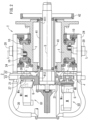
FIG. 2 is a vertical cross-sectional view of the same. -
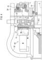
FIG. 3 is a partially enlarged view of the same portion of the transport device in one motor M. -
FIG. 4 is a partially enlarged view of the transport device in a motor M next to the one motor M. -
FIG. 5 is a front view illustrating a second embodiment of the transport device of the present invention. -
FIG. 6 is a vertical cross-sectional view of the same. -
FIG. 7 is an enlarged view of the same portion. -
FIGS. 8(a) and (b) are a front view and a cross-sectional view illustrating a transmission mechanism disclosed in Patent No. 4054191. - In
FIGS. 2 ,3 ,4 ,6 , and7 , some components are illustrated by gray color instead of hatching indicating a cross section to make the drawings easy to view. - The present invention will be understood more clearly from the following description of preferred embodiments taken in conjunction with the accompanying drawings. Note however that the embodiments and the drawings are merely illustrative and should not be taken to define the scope of the present invention. The scope of the present invention shall be defined only by the appended claims. In the accompanying drawings, like reference numerals denote like components throughout the plurality of figures.
- Embodiments of the present invention will be described below according to the drawings.
FIGS. 1 to 4 illustrate a first embodiment.
FIG. 1 is a schematic front view of a transport device T and other parts according to the first embodiment of the present invention. - Each of a plurality of
pads 20 rotates along a circulation track of the transport device T while the speed is changed, receives a workpiece W from adelivery roll 50 at a reception position P and delivers the workpiece W onto atransfer roll 51 at a delivery position P1. - The transport device T includes a
transmission mechanism 2 described below, for eachpad 20. Thetransmission mechanism 2 is driven by a motor M provided for eachpad 20. - As illustrated in
FIG. 2 , the transport device T includes ahollow rotation shaft 41 having an axial line S serving as a rotation center, and arotation body 21 that rotates around therotation shaft 41 integrally with therotation shaft 41. Each of thepads 20 holds and transports the workpiece W while a peripheral speed (angular velocity) thereof is changed with respect to therotation shaft 41. - Next, details of the
transmission mechanism 2 of this embodiment will be described.
Eachtransmission mechanism 2 includes acrank arm 22 that swings by an input from an output shaft M1 of the motor M ofFIG. 2 , and alink lever 23 that connects adistal end 25 of thecrank arm 22 and thepad 20 ofFIG. 1 . - As illustrated in
FIG. 1 , therotation body 21 is attached with a plurality ofcrank arms 22 that swing around aswing center 22c. The swing centers 22c of a plurality of thecrank arms 22 are arranged at an equal angular pitch in a virtual circumference. The interval of theswing centers 22c of eachcrank arm 22 is invariable. The swing centers 22c of thecrank arms 22 rotate at the same angular velocity together with therotation body 21 ofFIG. 2 . - In
FIG. 2 , the output shaft M1 of the motor M is connected to theswing center 22c of thecrank arm 22 via a decelerator G, and reciprocating rotates to cause thecrank arm 22 to swing around theswing center 22c. - The
crank arm 22 ofFIG. 1 periodically swings within a certain angular range, and thedistal end 25 of thecrank arm 22 periodically swings. That is, inFIG. 1 , during deceleration, thedistal end 25 of thecrank arm 22 is displaced by an angle α in a transport direction along the circulation direction R from theswing center 22c of thecrank arm 22, and, during acceleration, thedistal end 25 is displaced by an angle β in a direction opposite to the transport direction. - A
link lever 23 pin-connected to thedistal end 25 of thecrank arm 22 and aconnection block 24 pin-connected to thelink lever 23 are also displaced in conjunction with swing of thedistal end 25 of thecrank arm 22. The swing of thecrank arm 22 causes theconnection block 24 to be displaced in a peripheral direction with respect to theswing center 22c of thecrank arm 22, and therefore, the intervals between connection blocks 24 located forward and rearward also change. As a result, an angular velocity of theholding pad 20 arranged in theconnection block 24 changes and an interval in the circulation direction R betweenpads - A range (α + β) of swing of the
crank arm 22 is determined by a range of a rotation angle of the motor M. Accordingly, by controlling the range of the rotation angle of the motor M, the range (α + β) of the swing and also the interval betweenpads - Next, further details of the transport device T will be described.
- In
FIG. 2 , therotation shaft 41 is rotatably supported by afixation drum 1. Thefixation drum 1 is provided with a pair ofguide members 10. Theguide members 10 rotatably support thepad 20 with respect to thefixation drum 1 and guide the circulation of thepad 20.
Thefixation drum 1 is fixed to a frame of an instrument (not illustrated). - The
rotation shaft 41 is provided so as to penetrate thefixation drum 1. Aninput unit 42 that inputs a drive force to therotation shaft 41 is attached to afirst end 411 that is one end projecting from thefixation drum 1 in therotation shaft 41. - The
rotation body 21 is attached to asecond end 412 that is the other end projecting from thefixation drum 1 of therotation shaft 41. Therotation body 21 is fixed to therotation shaft 41 so as to rotate around the axial line S integrally with therotation shaft 41. Therotation body 21 is arranged in between thetransmission mechanisms 2 and the motors M in a direction in which the axial line S extends. - Each motor M is fixed to the
rotation body 21 via each decelerator G. In this manner, each motor M is arranged in the other side opposite to one side in which theinput unit 42 is arranged in thefixation drum 1. Each motor M may be fixed to therotation body 21 via the decelerator G and a joint J. - That is, the
rotation body 21 includes aninside surface 26 and anoutside surface 27. A plurality of thepads 20 and thefixation drum 1 are arranged in between theinput unit 42 and theinside surface 26 of therotation body 21, thefixation drum 1 being configured to rotatably support thepads 20. On the other hand, each motor M is attached to theoutside surface 27 opposite to theinside surface 26 in therotation body 21. In this manner, thefixation drum 1 and thepad 20 are arranged in theinside surface 26 side of therotation body 21 and each motor M is arranged in theoutside surface 27 side of therotation body 21. - In
FIG. 1 , each motor M attached to therotation body 21 is arranged at an equal angular pitch in a virtual circumference around the axial line S of the rotation shaft 41 (FIG. 3 ). As illustrated inFIG. 2 , therotation body 21 is arranged such that the output shafts M1 of the motors M are parallel to the direction in which the axial line S of therotation shaft 41 extends. In this manner, each motor M can be efficiently arranged in a dead space generated due to a suctionair wiring material 30 of thepad 20.
A workpiece is sucked and held to eachpad 20 by air sucked through thewiring material 30, that is, a negative pressure of the suction air. -
FIGS. 3 and4 illustrate motors M adjacent to each other in the circulation direction R, the decelerator G, and the like.
As illustrated inFIGS. 3 and4 , motors M adjacent to each other among each motor M are arranged by being offset (seeFIG. 2 ) from each other in the axial line S direction of therotation shaft 41. That is, each motor M includes each decelerator G connected to the output shaft M1, and attachment bases (attachment flanges) MB of decelerators G adjacent to each other among each decelerator G are arranged by being offset from each other in the axial line S direction of therotation shaft 41. Each decelerator G is attached to therotation body 21 via the attachment base MB.
More specifically, as illustrated inFIG. 3 , in one motor M among each motor M inFIG. 1 , the output shaft G1 of the decelerator G is connected directly to thecrank arm 22 of thetransmission mechanism 2.
On the other hand, as illustrated inFIG. 4 , in the motor M next to the one motor M described above among each motor M ofFIG. 1 , the output shaft G1 of the decelerator G is connected to thecrank arm 22 of thetransmission mechanism 2 via the joint J.
As illustrated inFIG. 2 , the decelerator G has a diameter larger than that of the motor M. The attachment bases MB have a substantially rectangular shape indicated by a virtual line inFIG. 1 , and the attachment bases MB adjacent to each other interfere with each other in a plan view. Therefore, as illustrated inFIGS. 3 and4 , by offsetting the attachment bases MB adjacent to each other (arranging the attachment bases MB adjacent to each other such that their positions are shifted from each other) in the axial line S direction, this interference can be prevented, so that the motors M can be arranged densely and a large number ofpads 20 can be provided as illustrated inFIG. 1 . - As illustrated in
FIG. 2 , the decelerator G is connected to each motor M and the motor M and the decelerator G connected to each other constitute a unit. All units include a first unit U1 belonging to one group and a second unit U2 belonging to the other group. InFIG. 1 , the attachment base MB of the decelerator G (FIG. 2 ) of the second unit U2 belonging to the other group is indicated by gray color. - As illustrated in
FIG. 1 , the first unit U1 and the second unit U2 are adjacent to each other in the peripheral direction. The attachment bases MB of the units adjacent to each other are arranged so as to overlap each other in the front view ofFIG. 1 . However, they are offset from each other as described above, the attachment bases MB adjacent to each other do not interfere with each other.
This feature will be described below more specifically. -
FIG. 3 illustrates one representation of a plurality of first units U1.
The first unit U1 illustrated inFIG. 3 includes the motor M, the decelerator G, and the attachment base MB. In a group of this first unit U1, although not illustrated, each motor M is arranged at the same position in the axial line S direction, each decelerator G is arranged at the same position in the axial line S direction, and each attachment base MB is arranged at the same position in the axial line S direction. -
FIG. 4 illustrates one representation of a plurality of second units U2.
The second unit U2 illustrated inFIG. 4 includes the joint J in addition to the motor M, the decelerator G, and the attachment base MB thereof. In a group of this second unit U2, although not illustrated, each motor M is arranged at the same position in the axial line S direction, each decelerator G is arranged at the same position in the axial line S direction, and each attachment base MB is arranged at the same position in the axial line S direction. Furthermore, each joint J is arranged at the same position in the axial line S direction. - That is, the motor M of the first unit U1 and the motor M of the second unit U2 of
FIG. 2 are offset from each other in the axial line S direction by an amount corresponding to the length of the joint J. As similar to this, the decelerator G of the first unit U1 and the decelerator G of the second unit U2 are also offset from each other and the attachment base MB of the first unit U1 and the attachment base MB of the second unit U2 are also offset from each other. - Accordingly, the attachment bases MB adjacent to each other that are viewed as if they overlap each other in
FIG. 1 do not interfere with each other. - When the number of groups of the units U1 and U2 are two, the total number of the units U1 and U2 and the number of the motors M are a multiple of two. For example, in the case of this example, the number of each of these is 10.
- The number of groups may be three or more. In that case, the number of units may not be a multiple of two and may not be a multiple of three. However, in consideration of the degree of accommodation of the device in the axial line S direction and the number of components, it is preferable that the number of groups is two.
- In this example, the offset described above is achieved by providing the joint J in
FIG. 2 . However, a spacer or the like may be provided as long as it can offset the positions in the axial line S direction, or otherwise, the shape of the crank arm may be changed. - As described above, the motor M is attached in the
outside surface 27 opposite to the side in which thepad 20 in therotation body 21 ofFIG. 2 is arranged. On the other hand, thecrank arm 22 is arranged along theinside surface 26 opposite to theoutside surface 27 of therotation body 21.
The output shaft M1 of the motor M is connected to theswing center 22c of thecrank arm 22 via the decelerator G, and causes thecrank arm 22 to swing around theswing center 22c. - In
FIG. 1 , in the case of this example, thepad 20 causes theconnection block 24 to turn around a normal line L of the circulation direction R by 90° and causes the workpiece W to turn by 90°. That is, when thepad 20 inFIG. 1 receives the workpiece W from thedelivery roll 50 at the reception position P, thepad 20 turns while changing a speed, circulates to the delivery position P1, and delivers the workpiece W onto thetransfer roll 51 at the delivery position. - After this deliver operation, the
pad 20 turns while changing the speed during circulation from the delivery position P1 in the circulation direction R, circulates to the reception position P, and receives the workpiece W at the reception position P. These operations are consecutively performed by eachpad 20, so that the workpieces W are successively transported. - The mechanism in which the
pad 20 inFIGS. 3 and4 turns around the normal line L by 90°may include a knownperipheral surface cam 1c or the like. Such a mechanism is disclosed inWO2005/075163 , for example, and the entire description of which are incorporated herein. - The
pad 20 inFIG. 1 sucks the workpiece W at the reception position P by a negative pressure, then holds the workpiece W, circulates along the circulation direction R, and releases the negative pressure in the upstream position further than the delivery position P1. - Next, the details of the operation of the transport device T at the time of transport will be described.
- In
FIG. 2 , when therotation shaft 41 rotates at a substantially constant angular velocity by the rotation force from theinput unit 42, thetabular rotation body 21, the motor M, and theswing center 22c of thecrank arm 22 ofFIG. 1 also rotate at a constant angular velocity. - In a first path (upper part in the drawing) from the reception position P to the delivery position P1 in
FIG. 1 , eachpad 20 holds the workpiece W, and, in this example, thepads 20 adjacent to each other approach each other while eachpad 20 is decelerated. On the other hand, in a second path (lower part in the drawing) from the delivery position P1 to the reception position P inFIG. 1 , eachpad 20 does not hold the workpiece W, and, in this example, thepads 20 adjacent to each other go away from each other while the speed of eachpad 20 is accelerated. - At the time of deceleration of the
pad 20 ofFIG. 1 , that is, in the first path of the upper part close to the delivery position P1, the motor M rotates in a first direction such that the rotation force in a reverse direction ΔR1 is loaded to thecrank arm 22 with respect to the circulation direction R of thepad 20. That is, the motor M rotates in the first direction so as to impart a negative angular acceleration to theswing center 22c of thecrank arm 22 such that a lead angle α of thecrank arm 22 becomes small. - On the other hand, at the time of acceleration of the
pad 20 ofFIG. 1 , that is, in the second path of the lower part close to the reception position P, the motor M rotates in a second direction such that the rotation force in the same direction ΔR2 as the circulation direction R of thepad 20 is loaded to thecrank arm 22. That is, the motor M rotates in the second direction so as to impart a positive angular acceleration to theswing center 22c of thecrank arm 22 such that a delay angle β of thecrank arm 22 becomes small. - In this manner, the
crank arm 22 swings around theswing center 22c during the circulation while theswing center 22c of thecrank arm 22 rotates in the circulation direction R of thepad 20 at a constant angular velocity. As a result, thedistal end 25 of thecrank arm 22 accelerates or decelerates, and thepad 20 connected to thedistal end 25 via thelink lever 23 and theconnection block 24 circulates while thepad 20 is also accelerated and decelerated. - Although the
pad 20 circulates along a circular track while being guided by the guide member 10 (FIG. 3 ), since thedistal end 25 ofFIG. 1 is not along the circular track, thelink lever 23 is interposed. -
FIGS. 5 to 7 illustrate a second embodiment.
The configurations of the second embodiment different from those of the first embodiment will be mainly described below. - In the above-described first embodiment, the
rotation body 21 inFIG. 1 is continuous in the circulation direction R. However, in the second embodiment, therotation bodies 21 ofFIG. 5 are separated in units of eachpad 20 in the circulation direction R. In the above-described first embodiment, thetransmission mechanism 2 ofFIG. 1 includes thecrank arm 22 and thelink lever 23 for eachpad 20. However, in the second embodiment, onesun gear 2L ofFIG. 6 and aplanetary gear 2S provided for eachpad 20 are provided. Details of these will be described below. - In
FIG. 6 , thesun gear 2L rotates at a substantially constant speed integrally with therotation shaft 41. On the other hand, therotation body 21 circulates together with thepad 20 while the speed is accelerated or decelerated in the circulation direction R ofFIG. 5 . - As illustrated in the enlarged view of
FIG. 7 , the circulation track of eachrotation body 21 is defined with respect to thefixation drum 1 via theguide member 10. Thepad 20 is supported to eachrotation body 21 such that thepad 20 can turn around the normal line L. - In
FIG. 7 , eachrotation body 21 is fixed with the motor M for speed change. The output shaft M1 of the motor M is connected to theplanetary gear 2S via the joint J. Theplanetary gear 2S is meshed with thesun gear 2L. - An overview of the operation of the transport device T of the second embodiment will be described.
InFIG. 5 , when thesun gear 2L rotates in the circulation direction R now, theplanetary gear 2S meshed with thesun gear 2L and therotation body 21 also circulate in the circulation direction R. On the other hand, when the output shaft M1 (FIG. 6 ) of the motor M rotates in the same direction as the circulation direction R of therotation body 21, the angular velocity of circulation of theplanetary gear 2S and therotation body 21 is increased. - Accordingly, when the rotation speed of the output shaft M1 (
FIG. 6 ) of the motor M increases or decreases, the rotation speed of therotation body 21 and the rotation speed of thepad 20 also increase or decrease. - For example, when the
pad 20 circulates from the reception position P to the delivery position P1 ofFIG. 5 , if the rotation speed of the motor M is increased, the circulation speed in the circulation direction R of therotation body 21 and thepad 20 is accelerated, so that the interval between thepads - On the other hand, when the
pad 20 circulates from the delivery position P1 to the reception position P ofFIG. 5 , if the rotation speed of the motor M becomes small, the circulation speed in the circulation direction R of therotation body 21 and thepad 20 is decelerated, so that the interval between thepads - In this manner, re-pitch operation of the
pad 20 is achieved by the acceleration or deceleration of the output shaft M1 (FIG. 6 ) of the motor M. - The first and second embodiments described above include specific inventions below.
- Preferably, the
transmission mechanisms 2 each include thecrank arm 22 that swings by an input from the output shaft M1 of each motor M, and thelink lever 23 that connects thedistal end 25 of thecrank arm 22 and thepad 20.
In this case, components and structures that are conventionally manufactured can be adopted, so that detailed designs are made easy. - More preferably, the
rotation body 21 is fixed to therotation shaft 41 so as to rotate around the axial line S integrally with therotation shaft 41, the output shafts M1 of the motors M are connected to theswing center 22c of thecrank arm 22 and configured to cause thecrank arm 22 to swing around theswing center 22c.
In this case, the structure in which the motor M causes thecrank arm 22 to swing can be easily achieved. - More preferably, the motors M are attached to the
outside surface 27 opposite to the side in which thepads 20 are arranged in therotation body 21, and thecrank arm 22 is arranged along theinside surface 26 opposite to theoutside surface 27 of therotation body 21.
In this case, since the motor M and thecrank arm 22 are attached to twoside surfaces rotation body 21, the motor M and thecrank arm 22 are made easy to be attached to therotation body 21. - Preferably, the motors M adjacent to each other among each motor M are arranged by being offset from each other in the axial line S direction of the
rotation shaft 41.
In this case, the motors M adjacent to each other can be prevented from interfering with each other, so that a large number of pads can be arranged densely. - Preferably, the motors M respectively include each decelerator G connected to the output shaft M1, and the attachment bases MB of the decelerators G adjacent to each other among each decelerator G are arranged by being offset from each other in the axial line S direction of the
rotation shaft 41.
In this case, the attachment bases of the decelerators that are larger than the motor can be prevented from interfering with each other, so that a large number of pads can be arranged densely. - Preferably, the output shaft G1 of the decelerator G of one motor M among each motors M are connected directly to the
transmission mechanism 2, and the output shaft G1 of the decelerator G of the motor M next to the one motor M among each motors M is connected to thetransmission mechanism 2 via the joint J.
In this case, the offset of the decelerator G is enabled by the joint J and the offset described above is enabled in the motor and the decelerator having the same shape and structure. - Preferably, a plurality of the
rotation bodies 21 are provided so as to be separated from each other for eachpad 20, and eachtransmission mechanism 2 includes thesun gear 2L that rotates integrally with therotation shaft 41, and aplanetary gear 2S that is connected to the output shaft M1 of the motor M fixed to therotation body 21 and rotates. - In this case, a novel structure of re-pitch can be provided, and also, the motor M does not need to be rotated in forward and reverse directions, so that the speed change of the
pad 20 becomes smooth. - Preferably, the
input unit 42 that inputs the drive force to therotation shaft 41 is further provided, - the plurality of
pads 20 are arranged between theinput unit 42 and theinside surface 26 of therotation body 21, - the motor M is attached to the
outside surface 27 opposite to theinside surface 26 in therotation body 21, thepad 20 is arranged in theinside surface 26 side of therotation body 21, and the motor M is arranged in theoutside surface 27 side of therotation body 21. - Preferably, the
fixation drum 1 that rotatably supports therotation shaft 41, and - the
guide member 10 that rotatably supports thepad 20 with respect to thefixation drum 1 and guides the circulation of thepad 20 are further provided, - the
rotation shaft 41 is provided so as to penetrate thefixation drum 1, - the
input unit 42 that inputs the drive force to therotation shaft 41 is attached to thefirst end 411 that is one end of therotation shaft 41 in the axial direction, - the
rotation body 21 is attached to thesecond end 412 that is the other end of therotation shaft 41, and - as a result, each motor M is arranged in the other side opposite to the one side in which the
input unit 42 is arranged in thefixation drum 1. - In these cases, the motor M can be arranged in the side opposite to the
input unit 42, which makes the arrangement of the motor M easy. - The preferable embodiments are described above with reference to the drawings. However, a skilled person in the art would easily conceive of various variations and modifications within an obvious scope with reference to this specification.
For example, during movement of the workpiece from the reception position to the delivery position, the workpiece may not be rotated around the normal line by 90°. Furthermore, the pad may be decelerated or accelerated between the reception position and the delivery position.
Furthermore, the workpiece may be a consecutive sheet that is folded during transporting.
Accordingly, variations and modifications as described above are construed as being within the scope of the present invention defined by the claims. - The present invention can be used in transporting in manufacturing of various articles such as a disposable diaper or a diaper.
-
- 1: Fixation drum
- 1c: Peripheral surface cam
- 10: Guide member
- 2: Transmission mechanism
- 2L: Sun gear
- 2S: Planetary gear
- 20: Pad
- 21: Rotation body
- 22: Crank arm
- 22c: Swing center
- 23: Link lever
- 24: Connection part
- 25: Distal end
- 26: Inside surface
- 27: Outside surface
- 30: Wiring material
- 41: Rotation shaft
- 42: Input unit
- 411: First end
- 412: Second end
- 50: Delivery roll
- 51: Transfer roll
- M: Motor
- M1: Output shaft
- MB: Attachment base G: Decelerator G1: Output shaft
- J: Joint
- P: Reception position
- P1: Delivery position
- R: Circulation direction
- S: Axial line
- L: Normal line
- W: Workpiece
- T: Transport device
- α: Lead angle
- β: Delay angle
- ΔR1: Opposite direction
- ΔR2: Same direction
- U1: First unit
- U2: Second unit
Claims (10)
- A transport device having a plurality of pads 20 that each hold a workpiece W constituting a part of a wearing article and transport the workpiece W while a peripheral speed is changed, the transport device comprising:a rotation shaft 41 having an axial line S serving as a rotation center;the plurality of pads 20 that each hold and transport the workpiece W while the peripheral speed is changed with respect to the rotation shaft 41;transmission mechanisms 2 that respectively change speeds of the pads 20; andmotors M each provided for the respective pads 20 and each including an output shaft M1 for driving the respective transmission mechanisms 2,the transport device being provided with a rotation body 21 that rotates around the axial line S and is arranged in between each of the transmission mechanisms 2 and each of the motors M in a direction in which the axial line S extends,wherein each of the motors M is attached to the rotation body 21, and each of the motors M is arranged around the axial line S of the rotation shaft 41 such that the output shaft M1 is parallel to the direction in which the axial line S of the rotation shaft 41 extends.
- The transport device according to claim 1,wherein the transmission mechanisms 2 each includea crank arm 22 that swings by an input from the output shaft M1 of the respective motors M, and a link lever 23 that connects a distal end 25 of the crank arm 22 and the respective pads 20.
- The transport device according to claim 2,wherein the rotation body 21 is fixed to the rotation shaft 41 so as to rotate around the axial line S integrally with the rotation shaft 41, andthe output shaft M1 of the respective motors M is connected to a swing center 22c of the crank arm 22 and configured to cause the crank arm 22 to swing around the swing center 22c.
- The transport device according to claim 3,wherein the motors M are each attached to an outside surface 27 opposite to a side in which the pads 20 are arranged in the rotation body 21, andthe crank arm 22 is arranged along an inside surface 26 opposite to the outside surface 27 of the rotation body 21.
- The transport device according to any one of claims 1 to 4,
wherein the motors M adjacent to each other among the motors M are arranged by being offset from each other in the axial line S direction of the rotation shaft 41. - The transport device according to claim 5,wherein the motors M respectively include decelerators G each connected to the output shaft M1, andattachment bases MB of the decelerators G adjacent to each other among the decelerators G are arranged by being offset from each other in the axial line S direction of the rotation shaft 41.
- The transport device according to claim 6,an output shaft G1 of one of the decelerators G of one of the motors M is connected directly to the respective transmission mechanisms 2, andan output shaft G1 of another one of the decelerators G of another one of the motors M next to the one motor M is connected to the respective transmission mechanisms 2 via a joint J.
- The transport device according to claim 1,wherein the rotation body 21 is provided in plural so as to be separated from each other for each of the pads 20, andeach of the transmission mechanisms 2 includes a sun gear 2L that rotates integrally with the rotation shaft 41, and a planetary gear 2S that is connected to the output shaft M1 of each of the motors M fixed to the rotation body 21 and rotates.
- The transport device according to any one of claims 1 to 8,further comprising an input unit 42 that inputs a drive force to the rotation shaft 41,wherein the plurality of pads 20 are arranged between the input unit 42 and an inside surface 26 of the rotation body 21,the motors M are attached to an outside surface 27 opposite to the inside surface 26 in the rotation body 21, the pads 20 are arranged in the inside surface 26 side of the rotation body 21, and the motors M are arranged in the outside surface 27 side of the rotation body 21.
- The transport device according to any one of claims 1 to 8,further comprising a fixation drum 1 that rotatably supports the rotation shaft 41, anda guide member 10 that rotatably supports the pads 20 with respect to the fixation drum 1 and guides circulation of the pads 20,wherein the rotation shaft 41 is provided so as to penetrate the fixation drum 1,an input unit 42 that inputs a drive force to the rotation shaft 41 is attached to a first end 411 that is one end of the rotation shaft 41 in the axial direction,the rotation body 21 is attached to a second end 412 that is another end of the rotation shaft 41, andas a result, the input unit 42 is arranged in one side of the fixation drum 1 and each of the motors M is arranged in another side opposite to the one side.
Applications Claiming Priority (3)
| Application Number | Priority Date | Filing Date | Title |
|---|---|---|---|
| JP2021125052 | 2021-07-30 | ||
| JP2021184703A JP7110467B1 (en) | 2021-07-30 | 2021-11-12 | Conveyor |
| PCT/JP2022/027720 WO2023008211A1 (en) | 2021-07-30 | 2022-07-14 | Transport device |
Publications (2)
| Publication Number | Publication Date |
|---|---|
| EP4345035A1 true EP4345035A1 (en) | 2024-04-03 |
| EP4345035A4 EP4345035A4 (en) | 2024-11-06 |
Family
ID=82656905
Family Applications (1)
| Application Number | Title | Priority Date | Filing Date |
|---|---|---|---|
| EP22849274.0A Pending EP4345035A4 (en) | 2021-07-30 | 2022-07-14 | Transport device |
Country Status (5)
| Country | Link |
|---|---|
| US (1) | US20240327135A1 (en) |
| EP (1) | EP4345035A4 (en) |
| JP (2) | JP7110467B1 (en) |
| CN (1) | CN117730044A (en) |
| WO (1) | WO2023008211A1 (en) |
Families Citing this family (1)
| Publication number | Priority date | Publication date | Assignee | Title |
|---|---|---|---|---|
| CN118049470B (en) * | 2023-02-23 | 2025-11-04 | 泉州市汉威机械制造有限公司 | A new type of high-speed electronic speed change device |
Family Cites Families (20)
| Publication number | Priority date | Publication date | Assignee | Title |
|---|---|---|---|---|
| JPH04371416A (en) * | 1991-06-18 | 1992-12-24 | Dainippon Printing Co Ltd | Work palletizing device |
| US6722494B2 (en) * | 1999-12-16 | 2004-04-20 | Zuiko Corporation | Method and device for transportation |
| JP3798298B2 (en) * | 2000-12-01 | 2006-07-19 | 株式会社瑞光 | Rotating device, method for conveying worn article, and method for conveying web |
| EP1726414B1 (en) | 2004-02-05 | 2013-03-27 | Zuiko Corporation | Web processing device |
| JP3898195B2 (en) | 2004-04-15 | 2007-03-28 | 東亜機工株式会社 | Work transfer device |
| ATE392380T1 (en) * | 2005-10-05 | 2008-05-15 | Fameccanica Data Spa | DEVICE FOR ADJUSTING THE DISTANCE BETWEEN OBJECTS TO BE TRANSPORTED |
| ES2329841T3 (en) | 2007-01-17 | 2009-12-01 | Fameccanica.Data S.P.A. | DEVICE TO CHANGE SEPARATION BETWEEN ITEMS CARRIED OUT AND TO ROTATE THESE ITEMS. |
| US9944487B2 (en) * | 2007-02-21 | 2018-04-17 | Curt G. Joa, Inc. | Single transfer insert placement method and apparatus |
| ES2922456T3 (en) * | 2007-02-21 | 2022-09-15 | Joa Curt G Inc | Simple transfer insert placement method and apparatus |
| JP5830790B2 (en) * | 2010-06-04 | 2015-12-09 | 株式会社瑞光 | Folding device, folding system and folding method for disposable wearing articles |
| US10117788B2 (en) * | 2012-07-06 | 2018-11-06 | Zuiko Corporation | Transport method, manufacturing method for disposable wearable article, as well as wearable article, and transport device |
| ITBO20130654A1 (en) * | 2013-11-27 | 2015-05-28 | Gdm Spa | TREATMENT AND APPLICATION DEVICE FOR PACKAGING OF ABSORBENT ITEMS. |
| JP2016050095A (en) | 2014-09-01 | 2016-04-11 | 日本電気硝子株式会社 | Transfer device of tabular body |
| EP3254994A1 (en) * | 2016-06-10 | 2017-12-13 | Sidel Participations | A conveying wheel for transporting articles and an apparatus for handling articles including at least one such conveying wheel |
| US10905597B2 (en) * | 2016-07-13 | 2021-02-02 | Zuiko Corporation | Conveying device and method for manufacturing disposable wearable article using same |
| WO2018085830A2 (en) * | 2016-11-07 | 2018-05-11 | R. A Jones & Co. | Apparatus and methods for product orientation and hole healing applications |
| WO2018212092A1 (en) * | 2017-05-16 | 2018-11-22 | 株式会社瑞光 | Sheet conveying device and sheet processing device provided with same, and method for conveying sheet and method for processing sheet using sheet conveying device |
| EP3903751B1 (en) * | 2018-12-28 | 2023-01-11 | Zuiko Corporation | Absorbent article manufacturing device and manufacturing method |
| JP7277583B2 (en) | 2019-06-11 | 2023-05-19 | 株式会社瑞光 | Conveying device and method |
| JP7237791B2 (en) * | 2019-10-03 | 2023-03-13 | ユニ・チャーム株式会社 | Linear motor type absorbent article material conveying device and absorbent article manufacturing method |
-
2021
- 2021-11-12 JP JP2021184703A patent/JP7110467B1/en active Active
-
2022
- 2022-07-14 JP JP2023538429A patent/JP7450129B2/en active Active
- 2022-07-14 EP EP22849274.0A patent/EP4345035A4/en active Pending
- 2022-07-14 WO PCT/JP2022/027720 patent/WO2023008211A1/en not_active Ceased
- 2022-07-14 CN CN202280049278.0A patent/CN117730044A/en active Pending
- 2022-07-14 US US18/573,619 patent/US20240327135A1/en active Pending
Also Published As
| Publication number | Publication date |
|---|---|
| US20240327135A1 (en) | 2024-10-03 |
| CN117730044A (en) | 2024-03-19 |
| JP7110467B1 (en) | 2022-08-01 |
| JP7450129B2 (en) | 2024-03-14 |
| EP4345035A4 (en) | 2024-11-06 |
| WO2023008211A1 (en) | 2023-02-02 |
| JPWO2023008211A1 (en) | 2023-02-02 |
| JP2023020815A (en) | 2023-02-09 |
Similar Documents
| Publication | Publication Date | Title |
|---|---|---|
| KR900003641B1 (en) | Gear head for manipulator | |
| JP5347148B2 (en) | A device that rotates the article by changing the pitch between conveyed articles | |
| JP6888080B2 (en) | A device for transferring and rotating an object | |
| US8281918B2 (en) | Unit for transferring products | |
| GB1560748A (en) | Conveyor device for conveying rod-like articles of the tobacco-processing industry | |
| CN1339010A (en) | Method and device for transportation | |
| US20240327135A1 (en) | Transport device | |
| CN113164288B (en) | Device and method for manufacturing absorbent article | |
| JP6253288B2 (en) | Article transfer device | |
| CN105213110A (en) | The commutation displacement assembly of hygienic article | |
| CN1229268C (en) | Transferring apparatus | |
| CN111587100A (en) | Method and apparatus for manufacturing disposable wearing article | |
| US20200229986A1 (en) | Device for applying segments of absorbent articles | |
| US6659928B2 (en) | Device for removing flat articles | |
| US11708224B2 (en) | Conveying apparatus and method | |
| JP2005145597A (en) | Speed control method and speed control apparatus | |
| EP4079660B1 (en) | Module for a sorting and transport line | |
| CN115103808B (en) | Sheet-like article conveying device and disposable wearing article manufacturing system equipped with the conveying device | |
| CN105269569A (en) | Tri-coaxial two-dimensional rotation and one-dimensional horizontal movement parallel mechanism | |
| CN113371465A (en) | Sending mechanism and sample tube sending device | |
| JP4481867B2 (en) | Transport device | |
| JP2005233310A (en) | Driving unit | |
| CN215207342U (en) | A sending mechanism and sample tube sending device | |
| CN113233107A (en) | Directional conveyer of shrimp body | |
| JPH08187837A (en) | Cam-controlled sheet paper acceleration system |
Legal Events
| Date | Code | Title | Description |
|---|---|---|---|
| STAA | Information on the status of an ep patent application or granted ep patent |
Free format text: STATUS: THE INTERNATIONAL PUBLICATION HAS BEEN MADE |
|
| PUAI | Public reference made under article 153(3) epc to a published international application that has entered the european phase |
Free format text: ORIGINAL CODE: 0009012 |
|
| STAA | Information on the status of an ep patent application or granted ep patent |
Free format text: STATUS: REQUEST FOR EXAMINATION WAS MADE |
|
| 17P | Request for examination filed |
Effective date: 20231220 |
|
| AK | Designated contracting states |
Kind code of ref document: A1 Designated state(s): AL AT BE BG CH CY CZ DE DK EE ES FI FR GB GR HR HU IE IS IT LI LT LU LV MC MK MT NL NO PL PT RO RS SE SI SK SM TR |
|
| A4 | Supplementary search report drawn up and despatched |
Effective date: 20241004 |
|
| DAV | Request for validation of the european patent (deleted) | ||
| DAX | Request for extension of the european patent (deleted) | ||
| RIC1 | Information provided on ipc code assigned before grant |
Ipc: B65H 29/24 20060101ALI20240927BHEP Ipc: A61F 13/15 20060101ALI20240927BHEP Ipc: B65G 47/86 20060101AFI20240927BHEP |
|
| RAP3 | Party data changed (applicant data changed or rights of an application transferred) |
Owner name: ZUIKO CORPORATION |