EP4344952A1 - Movable apparatus and installation method for imaging device - Google Patents
Movable apparatus and installation method for imaging device Download PDFInfo
- Publication number
- EP4344952A1 EP4344952A1 EP23199068.0A EP23199068A EP4344952A1 EP 4344952 A1 EP4344952 A1 EP 4344952A1 EP 23199068 A EP23199068 A EP 23199068A EP 4344952 A1 EP4344952 A1 EP 4344952A1
- Authority
- EP
- European Patent Office
- Prior art keywords
- movable apparatus
- angle
- vehicle
- resolution region
- view
- Prior art date
- Legal status (The legal status is an assumption and is not a legal conclusion. Google has not performed a legal analysis and makes no representation as to the accuracy of the status listed.)
- Withdrawn
Links
Images







Classifications
-
- B—PERFORMING OPERATIONS; TRANSPORTING
- B60—VEHICLES IN GENERAL
- B60R—VEHICLES, VEHICLE FITTINGS, OR VEHICLE PARTS, NOT OTHERWISE PROVIDED FOR
- B60R1/00—Optical viewing arrangements; Real-time viewing arrangements for drivers or passengers using optical image capturing systems, e.g. cameras or video systems specially adapted for use in or on vehicles
- B60R1/20—Real-time viewing arrangements for drivers or passengers using optical image capturing systems, e.g. cameras or video systems specially adapted for use in or on vehicles
- B60R1/22—Real-time viewing arrangements for drivers or passengers using optical image capturing systems, e.g. cameras or video systems specially adapted for use in or on vehicles for viewing an area outside the vehicle, e.g. the exterior of the vehicle
- B60R1/23—Real-time viewing arrangements for drivers or passengers using optical image capturing systems, e.g. cameras or video systems specially adapted for use in or on vehicles for viewing an area outside the vehicle, e.g. the exterior of the vehicle with a predetermined field of view
- B60R1/26—Real-time viewing arrangements for drivers or passengers using optical image capturing systems, e.g. cameras or video systems specially adapted for use in or on vehicles for viewing an area outside the vehicle, e.g. the exterior of the vehicle with a predetermined field of view to the rear of the vehicle
-
- B—PERFORMING OPERATIONS; TRANSPORTING
- B60—VEHICLES IN GENERAL
- B60R—VEHICLES, VEHICLE FITTINGS, OR VEHICLE PARTS, NOT OTHERWISE PROVIDED FOR
- B60R1/00—Optical viewing arrangements; Real-time viewing arrangements for drivers or passengers using optical image capturing systems, e.g. cameras or video systems specially adapted for use in or on vehicles
- B60R1/20—Real-time viewing arrangements for drivers or passengers using optical image capturing systems, e.g. cameras or video systems specially adapted for use in or on vehicles
- B60R1/22—Real-time viewing arrangements for drivers or passengers using optical image capturing systems, e.g. cameras or video systems specially adapted for use in or on vehicles for viewing an area outside the vehicle, e.g. the exterior of the vehicle
-
- G—PHYSICS
- G06—COMPUTING OR CALCULATING; COUNTING
- G06V—IMAGE OR VIDEO RECOGNITION OR UNDERSTANDING
- G06V10/00—Arrangements for image or video recognition or understanding
- G06V10/20—Image preprocessing
- G06V10/25—Determination of region of interest [ROI] or a volume of interest [VOI]
-
- G—PHYSICS
- G06—COMPUTING OR CALCULATING; COUNTING
- G06V—IMAGE OR VIDEO RECOGNITION OR UNDERSTANDING
- G06V20/00—Scenes; Scene-specific elements
- G06V20/50—Context or environment of the image
- G06V20/56—Context or environment of the image exterior to a vehicle by using sensors mounted on the vehicle
- G06V20/58—Recognition of moving objects or obstacles, e.g. vehicles or pedestrians; Recognition of traffic objects, e.g. traffic signs, traffic lights or roads
-
- H—ELECTRICITY
- H04—ELECTRIC COMMUNICATION TECHNIQUE
- H04N—PICTORIAL COMMUNICATION, e.g. TELEVISION
- H04N23/00—Cameras or camera modules comprising electronic image sensors; Control thereof
- H04N23/50—Constructional details
- H04N23/55—Optical parts specially adapted for electronic image sensors; Mounting thereof
-
- H—ELECTRICITY
- H04—ELECTRIC COMMUNICATION TECHNIQUE
- H04N—PICTORIAL COMMUNICATION, e.g. TELEVISION
- H04N23/00—Cameras or camera modules comprising electronic image sensors; Control thereof
- H04N23/60—Control of cameras or camera modules
- H04N23/61—Control of cameras or camera modules based on recognised objects
-
- H—ELECTRICITY
- H04—ELECTRIC COMMUNICATION TECHNIQUE
- H04N—PICTORIAL COMMUNICATION, e.g. TELEVISION
- H04N23/00—Cameras or camera modules comprising electronic image sensors; Control thereof
- H04N23/60—Control of cameras or camera modules
- H04N23/67—Focus control based on electronic image sensor signals
- H04N23/675—Focus control based on electronic image sensor signals comprising setting of focusing regions
-
- H—ELECTRICITY
- H04—ELECTRIC COMMUNICATION TECHNIQUE
- H04N—PICTORIAL COMMUNICATION, e.g. TELEVISION
- H04N23/00—Cameras or camera modules comprising electronic image sensors; Control thereof
- H04N23/60—Control of cameras or camera modules
- H04N23/698—Control of cameras or camera modules for achieving an enlarged field of view, e.g. panoramic image capture
-
- H—ELECTRICITY
- H04—ELECTRIC COMMUNICATION TECHNIQUE
- H04N—PICTORIAL COMMUNICATION, e.g. TELEVISION
- H04N23/00—Cameras or camera modules comprising electronic image sensors; Control thereof
- H04N23/90—Arrangement of cameras or camera modules, e.g. multiple cameras in TV studios or sports stadiums
-
- H—ELECTRICITY
- H04—ELECTRIC COMMUNICATION TECHNIQUE
- H04N—PICTORIAL COMMUNICATION, e.g. TELEVISION
- H04N23/00—Cameras or camera modules comprising electronic image sensors; Control thereof
- H04N23/95—Computational photography systems, e.g. light-field imaging systems
- H04N23/951—Computational photography systems, e.g. light-field imaging systems by using two or more images to influence resolution, frame rate or aspect ratio
-
- H—ELECTRICITY
- H04—ELECTRIC COMMUNICATION TECHNIQUE
- H04N—PICTORIAL COMMUNICATION, e.g. TELEVISION
- H04N5/00—Details of television systems
- H04N5/222—Studio circuitry; Studio devices; Studio equipment
- H04N5/262—Studio circuits, e.g. for mixing, switching-over, change of character of image, other special effects ; Cameras specially adapted for the electronic generation of special effects
- H04N5/265—Mixing
-
- H—ELECTRICITY
- H04—ELECTRIC COMMUNICATION TECHNIQUE
- H04N—PICTORIAL COMMUNICATION, e.g. TELEVISION
- H04N7/00—Television systems
- H04N7/18—Closed-circuit television [CCTV] systems, i.e. systems in which the video signal is not broadcast
- H04N7/181—Closed-circuit television [CCTV] systems, i.e. systems in which the video signal is not broadcast for receiving images from a plurality of remote sources
-
- B—PERFORMING OPERATIONS; TRANSPORTING
- B60—VEHICLES IN GENERAL
- B60R—VEHICLES, VEHICLE FITTINGS, OR VEHICLE PARTS, NOT OTHERWISE PROVIDED FOR
- B60R2300/00—Details of viewing arrangements using cameras and displays, specially adapted for use in a vehicle
- B60R2300/10—Details of viewing arrangements using cameras and displays, specially adapted for use in a vehicle characterised by the type of camera system used
- B60R2300/107—Details of viewing arrangements using cameras and displays, specially adapted for use in a vehicle characterised by the type of camera system used using stereoscopic cameras
-
- B—PERFORMING OPERATIONS; TRANSPORTING
- B60—VEHICLES IN GENERAL
- B60R—VEHICLES, VEHICLE FITTINGS, OR VEHICLE PARTS, NOT OTHERWISE PROVIDED FOR
- B60R2300/00—Details of viewing arrangements using cameras and displays, specially adapted for use in a vehicle
- B60R2300/40—Details of viewing arrangements using cameras and displays, specially adapted for use in a vehicle characterised by the details of the power supply or the coupling to vehicle components
- B60R2300/402—Image calibration
-
- B—PERFORMING OPERATIONS; TRANSPORTING
- B60—VEHICLES IN GENERAL
- B60R—VEHICLES, VEHICLE FITTINGS, OR VEHICLE PARTS, NOT OTHERWISE PROVIDED FOR
- B60R2300/00—Details of viewing arrangements using cameras and displays, specially adapted for use in a vehicle
- B60R2300/80—Details of viewing arrangements using cameras and displays, specially adapted for use in a vehicle characterised by the intended use of the viewing arrangement
- B60R2300/802—Details of viewing arrangements using cameras and displays, specially adapted for use in a vehicle characterised by the intended use of the viewing arrangement for monitoring and displaying vehicle exterior blind spot views
-
- H—ELECTRICITY
- H04—ELECTRIC COMMUNICATION TECHNIQUE
- H04N—PICTORIAL COMMUNICATION, e.g. TELEVISION
- H04N13/00—Stereoscopic video systems; Multi-view video systems; Details thereof
- H04N13/20—Image signal generators
- H04N13/204—Image signal generators using stereoscopic image cameras
Definitions
- the present invention relates to a movable apparatus such as an automobile, and an installation method for an imaging device.
- CMS camera monitor system
- UN-R46 regulation for indirect vision for automobiles
- CMS is also required to perform imaging and to be installed so as to reduce blind spots, similar to existing mirrors.
- CTA cross traffic alert
- automobiles equipped with a forward or backward monitoring device are each equipped with a wide-angle camera capable of capturing an image in a wide range ahead or behind a vehicle.
- Japanese Patent No. 6349558 discloses that behind a vehicle is imaged with a camera including an optical system capable of imaging a portion of an imaging region with high resolution.
- the camera with high resolution in a portion of the imaging region used in Japanese Patent No. 6349558 cannot image a wide range with high resolution, and thus, when it is necessary to image a wide range with high resolution, a large number of cameras need to be provided to cover a wide range.
- a movable apparatus is a movable apparatus including a first imaging device including an optical system that forms an optical image, which has a low resolution region near an optical axis and a high resolution region outside the low resolution region, on a light receiving surface of an imaging element, in which the first imaging device is installed at a first installation position where an image is captured in at least one of a horizontal backward direction of one side surface of the movable apparatus, right or left direction in a horizontal direction ahead a driver's seat of the movable apparatus, and a downward direction ahead the movable apparatus in the high resolution region of the optical system.
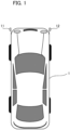
- Fig. 1 is a diagram illustrating a positional relationship between a camera unit and a vehicle in the first embodiment.
- Fig. 1 is a diagram illustrating an example in which a camera unit 11 as a first imaging device is installed on the front left side of a vehicle 1, which is an automobile, and a camera unit 12 is installed on the front right side.
- description is given on the assumption that two camera units are installed in a vehicle 1, but the number of camera units is not limited to two, and at least one or more camera units may be provided.
- the camera units 11 and 12 are installed to be capable of imaging the side to the backward of the vehicle 1 from the side surfaces thereof in order to capture a video for an electronic side mirror, imaging at least one of the right and left sides of the forward direction of the vehicle 1 to be able to capture a video for a front CTA, and capturing forward and downward videos for a forward monitoring device of the vehicle 1.
- Optical systems of the camera units 11 and 12 in the first embodiment generate an image circle having a characteristic that the peripheral angle of view has a higher resolution than the center in the optical axis direction, and form an image on a video element to be described later.
- optical characteristics of the camera units 11 and 12 are assumed to be substantially the same, and the characteristics will be exemplified using Fig. 2 .
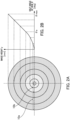
- Figs. 2A and 2B are diagrams illustrating optical characteristics of the optical system of the camera unit 11 in the first embodiment.
- Fig. 2A is a contour line diagram illustrating an image circle of the optical system of the camera unit 11 and an image height y at each half angle of view on a light receiving surface of an imaging element.
- Fig. 2B is a diagram illustrating projection characteristics of an image circle representing a relationship between an image height y of the optical system of the camera unit 11 and a half angle of view ⁇ .
- the half angle of view an angle formed by the optical axis and an incident light beam
- ⁇ is shown as the horizontal axis
- an imaging height (image plane) y on a light receiving surface (image plane) of the imaging element of the camera unit 11 is shown as the vertical axis.
- a configuration is adopted in which a projection characteristic y( ⁇ ) differs between a region with less than a predetermined half angle of view ⁇ a and a region with the half angle of view ⁇ a or more.
- an index represented by a differential value dy( ⁇ )/d ⁇ of the projection characteristic y( ⁇ ) at the half angle of view ⁇ is assumed to be a resolution, it can be said that the resolution increases as the inclination of the projection characteristic y( ⁇ ) in Fig. 2B becomes larger.
- the optical system of the camera unit 11 has an optical characteristic that the half angle of view is larger than the resolution of the region with a half angle of view less than ⁇ a in the region with the half angle of view ⁇ a or more.
- a region of a peripheral portion of the light receiving surface where a half angle of view ⁇ is equal to or greater than ⁇ a is referred to as a high resolution region 10a
- a region of the center of the light receiving surface where a half angle of view ⁇ is less than ⁇ a is referred to as a low resolution region 10b.
- the optical system in the first embodiment has a projection characteristic that an image height with respect to an angle of view per unit in the angle of view in the high resolution region is higher than that the angle of view in the low resolution region in the vicinity of the optical axis.
- the optical system has a low resolution region in the vicinity of the optical axis and has a high resolution region outside the low resolution region.
- a boundary circle between the high resolution region 10a and the low resolution region 10b is referred to as a resolution boundary
- a boundary image on a display screen corresponding to the resolution boundary is referred to as a display resolution boundary or simply a boundary image.
- the boundary between the high resolution region 10a and the low resolution region 10b is not limited to a circular shape, and may be an ellipse having a different projection characteristic y( ⁇ ) for each radial direction, or a distorted shape.
- a lens with the above-described characteristics is referred to as a stereoscopic projection lens
- a camera unit with a stereoscopic projection lens attached thereto is referred to as a stereoscopic projection camera.
- the center of gravity of the low resolution region 10b and the center of gravity of the high resolution region 10a on the light receiving surface of the imaging element of the camera unit substantially overlap each other, and the center of gravity of the high resolution region 10a substantially matches a position where the optical axis of the optical system of the camera unit intersects the light receiving surface of the imaging element.
- the center of gravity of the light receiving surface of the imaging element and the center of gravity of the high resolution region 10a may deviate from each other in a predetermined direction, and the center of gravity of the high resolution region 10a may deviate from the position where the optical axis of the optical system intersects the light receiving surface.
- Fig. 3 is a diagram illustrating the image processing system 100 in the first embodiment, and the image processing system 100 of Fig. 3 is mounted on the vehicle 1.
- the camera unit 11 includes an imaging unit 21 and a camera processing unit 31, and the camera unit 12 includes an imaging unit 22 and a camera processing unit 32.
- the imaging units 21 and 22 include stereoscopic projection lenses 21a and 22a and imaging elements 21b and 22b such as CMOS image sensors, respectively.
- the stereoscopic projection lenses 21a and 22a which are the optical systems of the camera units 11 and 12, are each constituted by one or more optical lenses, and each have optical characteristics as illustrated in Figs. 2A and 2B .
- the stereoscopic projection lenses 21a and 22a form (image) respective optical images on the light receiving surfaces of the imaging elements 21b and 22b, respectively.
- the imaging elements 21b and 22b function as imaging units, photoelectrically converting the formed optical images and outputting imaging signals.
- R, G, and B color filters are arranged in a Bayer array for each pixel on the light receiving surfaces of the imaging elements 21b and 22b, and pixel signals of R, G, and B are sequentially output from the imaging unit 21 as imaging signals.
- the camera processing units 31 and 32 have a function of processing imaging signals output from the imaging units 21 and 22, respectively.
- the camera processing units 31 and 32 include image processing units 31a and 32a, recognition units 31b and 32b, and camera information units 31c and 32c, respectively.
- a CPU as a computer and a memory storing a computer program as a storage medium are built into each of the camera processing units 31 and 32, and the CPU executes the computer program in the memory. Thereby, with this configuration, processing in the camera processing units 31 and 32 is executed.
- the camera processing units 31 and 32 are not limited to the configuration described above, and the image processing units 31a and 32a and the recognition units 31b and 32b may be constituted by hardware such as a dedicated circuit (ASIC), a processor (reconfigurable processor, DSP), or the like.
- ASIC dedicated circuit
- DSP reconfigurable processor
- the image processing units 31a and 32a perform various image correction processing such as white balance adjustment, gain/offset adjustment, gamma processing, color matrix processing, reversible compression processing, and distortion correction processing on the imaging signals output from the imaging units 21 and 22.
- the image processing units 31a and 32a are configured to perform distortion correction on the image signal of the low resolution region 10b and not to perform distortion correction on the image signal of the high resolution region 10a.
- image data input from the imaging units 21 and 22 in accordance with a Bayer array is subj ected to debayer processing and converted into RGB raster type image data.
- a portion of the above-described image processing may be performed by other blocks of the image processing system 100 other than the image processing units 31a and 32a.
- the recognition units 31b and 32b have a function of performing image recognition of a predetermined object (for example, an automobile, a person, an obstacle, or the like) from the image signals image-processed by the image processing units 31a and 32a, respectively, and outputting a first image recognition result to an integrated processing unit 40.
- a predetermined object for example, an automobile, a person, an obstacle, or the like
- the image recognition result is transmitted to the integrated processing unit 40 as a recognition result including the type of object and a set of coordinates.
- the recognition units 31b and 32b may receive prediction information including the type of obj ect and information on a moving direction of the object or priority recognition region information from an integrated control unit 41c of the integrated processing unit 40 and may perform image recognition processing.
- the camera information units 31c and 32c function as storing units that store camera information such as characteristic information on optical image characteristics and position and orientation information of the camera units, and store the camera information of the camera units 11 and 12 in the memory in advance.
- the camera information units 31c and 32c may store information from various sensors provided in the camera units 11 and 12, and the like.
- the stored camera information includes information such as characteristic information of the stereoscopic projection lenses 21a and 22a, the number of pixels of the imaging elements 21b and 22b, mounting position information and orientation (pitch, roll, yaw, and the like) of the camera units 11 and 12 in vehicle coordinates, an optical axis direction, and an imaging range.
- the camera information may also include information such as the gamma characteristics, sensitivity characteristics, a frame rate, and an image format of a video output from the camera processing unit 31.
- the mounting position information of the camera unit is stored in the memory in the camera information unit in advance as relative coordinates with respect to the vehicle 1 because the mounting position with respect to the vehicle is often determined for each camera unit.
- the camera information may be information unique to the imaging units 21 and 22 (for example, lens aberration characteristics, noise characteristics of the imaging elements, and the like).
- the camera information is transmitted to the integrated processing unit 40 and is referred to when the integrated processing unit 40 performs necessary image processing or the like in order to display the camera information on a display unit.
- the integrated processing unit 40 has a function of displaying video signals obtained from the camera units 11 and 12 on display devices such as a first display unit 50 and a second display unit 51, and a function of notifying a warning display unit 52 and a voice notification unit 53 of the video signals. Further, the integrated processing unit 40 has an image recognition function for an object straddling boundaries of imaging ranges of the camera units 11 and 12, and the like.
- the integrated processing unit 40 includes a system on chip (SOC) / field programable gate array (FPGA) 41, a CPU 42 as a computer, and a memory 43 as a storage medium.
- SOC system on chip
- FPGA field programable gate array
- description is given on the assumption that the integrated processing unit 40 is accommodated in a housing separate from the camera unit.
- Some or all of the functional blocks included in the integrated processing unit 40 and the like may be implemented by hardware or may be implemented by the CPU 42.
- a dedicated circuit (ASIC), a processor (reconfigurable processor, DSP), or the like can be used as the hardware.
- the CPU 42 performs various controls of the entire image processing system 100 by executing computer programs stored in the memory 43.
- the SOC / FPGA 41 includes an image processing unit 41a, a recognition unit 41b, and an integrated control unit 41c.
- the image processing unit 41a has a function of performing image processing such as resolution conversion for display on a display device based on the image signals and camera information acquired from the camera processing units 31 and 32.
- the camera information includes optical characteristics of the stereoscopic projection lenses 21a and 22a, the number of pixels of the imaging elements 21b and 22b, photoelectric conversion characteristics, y characteristics, sensitivity characteristics, format information of an image signal, coordinates of a mounting position and orientation information in the vehicle coordinates of the camera unit, and the like.
- the image processing unit 41a synthesizes the distortion-corrected image signal of the low resolution region 10b of each of the imaging units 21 and 22 and the image signal of the high resolution region 10a so that the image signals are smoothly connected, thereby forming an overall image for each of the imaging units 21 and 22.
- the image processing unit 41a performs image processing such as image rotation based on the camera information, particularly the arrangement position and orientation information of the camera, and transmits an image signal to the display device.
- the recognition unit 41b performs image recognition processing on a synthesized image obtained by connecting images from the imaging units 21 and 22, and performs image recognition of a predetermined object (for example, an automobile, a person, an obstacle, or the like) in a synthesized image obtained from the imaging units 21 and 22 to generate a second image recognition result.
- a predetermined object for example, an automobile, a person, an obstacle, or the like
- the recognition results (the type and coordinates of the object) obtained by the recognition units 31b and 32b may also be referred to.
- the recognition unit 41b performs image recognition on the synthesized image obtained from the imaging units 21 and 22, but image recognition may not be necessarily performed on the synthesized image.
- the recognition unit 41b can output a second image recognition result as a result of image recognition performed on an image signal in a region wider than a partial region in which image recognition is performed by the first image recognition unit among image signals acquired by an image acquisition unit.
- the integrated control unit 41c functions as an integrated processing unit that outputs an image recognition result integrated based on the reliability of the first image recognition result and the reliability of the second image recognition result. For example, when the recognition result of the recognition units 31b and 32b and the recognition result of the recognition unit 41b are different from each other, the integrated control unit 41c outputs an image recognition result integrated by adopting a recognition result with higher reliability.
- the proportion of an object in an image recognized by the recognition units 31b and 32b is compared with the proportion of the same object recognized by the recognition unit 41b in a screen, and a recognition result with a higher proportion is determined to have high reliability and is adopted.
- the integrated control unit 41c has a function of forming a video signal for displaying a desired image on the first display unit 50, the second display unit 51, or the like from an image-processed entire image for each of the imaging units 21 and 22.
- a frame for highlighting a recognized object, a CG for information and warnings on the type, size, position, speed, and the like of an object, and the like are generated.
- a CG of a boundary image for displaying a boundary may be generated based on characteristic information of the optical system such as display resolution boundary information acquired from the camera information units 31c and 32c. Then, display processing for superimposing these CG and characters on an image is performed.
- the first display unit 50, the second display unit 51, and the like display image signals and integrated image recognition results.
- the integrated control unit 41c communicates with a running control unit (ECU) 60 and the like via a communication unit, which is not illustrated in the drawing, provided therein by using protocols such as CAN, FlexRay, and Ethernet.
- ECU running control unit
- display processing for appropriately changing information to be displayed based on a vehicle control signal received from the running control unit (ECU) 60 or the like is performed. That is, for example, the range of an image to be displayed on the display unit, and the like can be changed in accordance with a moving state of a vehicle which is acquired in response to the vehicle control signal.
- the traveling control unit (ECU) 60 is a unit that is mounted on the vehicle 1 and includes a computer and memory for comprehensively performing drive control, direction control, and the like of the vehicle 1. From the running control unit (ECU) 60, information on the running (movement state) of the vehicle such as a running speed, a running direction, a shift lever, a shift gear, the state of a turn signal, the orientation of the vehicle obtained by a geomagnetic sensor or the like, and GPS information, and the like are input to the integrated processing unit 40 as vehicle control signals.
- the integrated control unit 41c may have a function of transmitting information such as the type, position, moving direction, moving speed, and the like of a predetermined object (such as an obstacle or the like) which are recognized by the recognition unit 41b to the running control unit (ECU) 60.
- a predetermined object such as an obstacle or the like
- the running control unit (ECU) 60 performs control necessary for avoiding obstacles such as stopping the vehicle, driving the vehicle, and changing the direction of travel.
- the running control unit (ECU) 60 functions as a movement control unit that controls the movement of the vehicle based on an integrated image recognition result.
- the first display unit 50 is a display device that is installed, for example, near the center of an upper portion ahead a driver's seat of the vehicle 1 in the vehicle width direction with a display screen directed toward the backward of the vehicle and function as an electronic rearview mirror.
- the first display unit 50 may be configured to be usable as a mirror when it is not used as a display by using a half mirror or the like.
- the first display unit 50 includes a touch panel and operation buttons and may be configured to acquire instructions from the user and output them to the integrated control unit 41c.
- the first display unit 50 can also be used as an electronic side mirror for confirming obstacles or the like on the right or left, as a display device displaying a video for front CTA instead of, for example, an optical side mirror of the related art.
- the first display unit 50 receives and displays a video signal generated by the integrated control unit 41c and having an angle of view required for display in accordance with the application of the first display unit.
- the second display unit 51 is a display device that is installed, for example, in the vicinity of an operation panel near the center ahead the driver's seat of the vehicle 1 in the vehicle width direction and functions as a display device for displaying, for example, a region in a lower direction ahead the vehicle. Similarly to the first display unit, the second display unit 51 also functions as a display device that receives a necessary imaging region generated in accordance with the application.
- the integrated control unit 41c receives and displays signals necessary for display in accordance with the application of the second display unit.
- the second display unit can display various control signals received from a navigation system, an audio system, and the running control unit (ECU) 60.
- the second display unit includes a touch panel and operation buttons and may be configured to be able to acquire instructions from the user.
- the second display unit 51 may be, for example, a display unit of a tablet terminal, and can also display an image by being connected to the integrated processing unit 40 in a wired manner and can also receive and display an image through a communication unit 62 in a wireless manner.
- a liquid crystal display, an organic EL display, or the like can be used as display elements of the first display unit 50 and the second display unit 51, and the number of display units is not limited to one.
- the integrated control unit 41c determines whether a moving object is included in an image based on recognition results output by the recognition units 31b and 32b and the recognition unit 41b, and outputs the recognition results.
- the moving object here is, for example, a bicycle, a pedestrian, and other vehicles, and are referred to as a detection target in the first embodiment.
- the recognition results output by the integrated control unit 41c include whether there is a detection target, the type and coordinates of a detection target, and speed information.
- the warning display unit 52 Based on the recognition result output from the integrated control unit 41c, the warning display unit 52 issues, for example, a side collision warning to the driver by using visual information.
- the warning display unit 52 may be constituted by, for example, an LED, and may be configured to perform lighting or blinking when the recognition result includes information indicating that there is a detection target.
- the warning display unit 52 may be constituted by a display such as a liquid crystal. In this case, when the recognition result includes information indicating that there is a detection target, an icon, character information, or the like is output to the display. Further, the warning display unit 52 can be installed, for example, in the vicinity of an end ahead the driver's seat of the vehicle 1 in the vehicle width direction with the display screen directed toward the driver.
- the warning display unit 52 may be installed, for example, near the first display unit 50 and the second display unit 51, or may be configured to be replaced with the first display unit 50 and the second display unit 51.
- the voice notification unit 53 outputs a sound based on the recognition result output from the integrated control unit 41c. For example, the driver can be notified of a sound by outputting the sound using a speaker. It is desirable to install, for example, the voice notification unit 53 near an end ahead the driver's seat of the vehicle 1 in the vehicle width direction.
- the integrated control unit 41c also functions as a warning condition determination unit and performs control so that the content of a warning output by the warning display unit 52 or the voice notification unit 53 is changed based on the coordinates and speed of the detection target obtained by the recognition units 31b to 32b and the recognition unit 41b.
- the integrated control unit 41c may be configured to control the warning display unit 52 so that the smaller a distance to the detection target is, the higher the degree of warning is.
- the integrated control unit 41c may be configured to determine whether the running speed of the host vehicle which is input from the running control unit (ECU) 60 is equal to or less than a predetermined value, and to display a warning on the warning display unit 52 or give a warning notification by the voice notification unit 53 only when the running speed is the predetermined value or less.
- the running speed of the host vehicle When the running speed of the host vehicle is high, there is a possibility that the detection target cannot be correctly recognized. Thus, with such a configuration, the possibility of performing correct side detection can be improved. At this time, it is desirable to set the predetermined value of the running speed of the host vehicle to 30 km/hkm/h.
- the integrated control unit 41c may be configured to determine whether the speed of the detection target is within a predetermined range, and to display a warning on the warning display unit 52 or give a warning notification by the voice notification unit 53 only when it is determined that the speed of the detection target is within the predetermined range. In this case, it is desirable to set a predetermined range of the speed of a predetermined detection target to 5 km/h or more and 20 km/h or less.
- the integrated control unit 41c determines whether the vehicle is turning right or left based on moving direction information of the host vehicle which is output from the running control unit (ECU) 60, and displays a warning on the warning display unit 52 or give a warning notification by the voice notification unit 53 only when the vehicle is turning right or left.
- the integrated processing unit 40 is mounted on the vehicle 1 in the first embodiment, some of the processing of the image processing unit 41a, the recognition unit 41b, and the integrated control unit 41c of the integrated processing unit 40 may be performed by an external server or the like via, for example, a network.
- the imaging units 21 to 24 as image acquisition units are mounted on the vehicle 1, but for example, some of the functions of the camera processing units 31 and 32 and the integrated processing unit 40 can be processed by an external server or the like.
- the running control unit (ECU) 60 it is possible to make the running control unit (ECU) 60 have some or all of the functions of the integrated processing unit 40.
- Reference numeral 61 denotes a storage unit, and the entire image for each of the imaging units 21 and 22 which is generated by the integrated processing unit 40 is recorded. Further, a CG such as a predetermined frame, characters, and a warning indicating a recognized object, and images having the CG superimposed thereon and displayed on the first display unit 50, the second display unit 51, and the like are recorded together with time, GPS information, and the like.
- the integrated processing unit 40 can also reproduce past information recorded in the storage unit 61 and display it on the first display unit 50 and the second display unit 51.
- the communication unit 62 which is a unit for communicating with an external server or the like via a network, can transmit information before being recorded in the storage unit 61 and past running history information and the like recorded in the storage unit 61 to an external server or the like and store them in the external server or the like.
- an image can be transmitted to an external tablet terminal or the like and displayed on the second display unit 51, which is a display unit of the tablet terminal.
- Traffic congestion information and various types of information can be acquired from an external server or the like and displayed on the first display unit 50 and the second display unit 51 via the integrated processing unit 40.
- Reference numeral 63 denotes an operation unit for inputting various instructions to the image processing system by a user's operation.
- the operation unit includes, for example, a touch panel, operation buttons, and the like.
- Figs. 4A and 4B are diagrams illustrating a relationship between characteristics of the optical system of the camera unit 11 installed in the vehicle 1 in the first embodiment and an imaging region required for display for an electronic side mirror and a front CTA.
- Fig. 4A is a side view of the vehicle 1 when viewed from the side
- Fig. 4B is a front view of the vehicle when viewed from the front.
- the origin of the X, Y, and Z directions in Fig. 4 is the installation position of the camera unit 11, and the X direction is a forward direction of the vehicle in the horizontal direction as illustrated in Fig. 4A .
- the Z direction is a left direction in the horizontal direction when facing the vehicle 1 as illustrated in Fig. 4B .
- the Y direction is an upward direction in the vertical direction as illustrated in Figs. 4A and 4B .
- a positive angle is set in the X direction and a negative angle is set in the -X direction with reference to the vertical direction.
- a positive angle is set in the Z direction and a negative angle is set in the -Z direction with reference to the vertical direction.
- E in the XY plane in Fig. 4A represents the driver's viewpoint position, which is the eye position of the driver at a seated position or the center position on the driver's seat surface.
- ⁇ v is the optical axis direction of the camera unit 11 and is an angle from the vertical direction.
- the optical axis of the imaging device is directed downward from an installation position.
- ⁇ v is an angle of view of the high resolution region 10a of the camera unit 11.
- ⁇ lv is an angle of view of the low resolution region 10b of the camera unit 11.
- cph is the optical axis direction of the camera unit 11 and is an angle from the vertical direction.
- ⁇ h is an angle of view of the high resolution region 10a of the camera unit 11.
- ⁇ lh is an angle of view of the low resolution region 10b of the camera unit 11.
- x in the XY plane in Fig. 4A is a horizontal distance between the camera unit 11 and a viewpoint position E of the driver.
- h1 is a vertical distance between the camera unit 11 and the ground.
- z in the YZ plane in Fig. 4B is a distance between the installation position (first installation position) of the camera unit 11 and the side surface of the vehicle 1.
- an imaging region specified region behind the vehicle side surface required for display of an electronic side mirror will be described with reference to Figs. 4 and 5 .
- Fig. 5 is a top plan view of the vehicle 1 in the first embodiment, and the X and Z directions correspond to those in Fig. 4 with the installation position of the camera unit 11 as the origin.
- Specified regions behind the vehicle side surfaces are regions on the ground as indicated by hatching in Fig. 4A and Fig. 5 , and are regions that need to be confirmed by the driver with the side mirror of the vehicle.
- the specified regions behind the vehicle side surfaces are regions on the ground surface defined by a width w1 from the side surface of the vehicle body at a distance d1 from the driver's viewpoint position E to the backward side and a width w2 from the side surface of the vehicle body at a distance d2, and a region on the passenger seat side is assumed to be region1, and a region on the driver's seat side is assumed to be region2.
- region1 and region2 have shapes line-symmetrical to the longitudinal centerline of the vehicle 1.
- the camera unit 11 installed on the side of the passenger seat can capture an image in the horizontal direction with high resolution while imaging the specified region region1 behind the vehicle side surface. Since a distant region of region1, which is a specified region behind the vehicle side surface, extends to infinity behind the vehicle, the camera unit 11 is installed to be able to capture an image of infinity, that is, the width w2 in the horizontal direction. In order to confirm a distant object away from the driver with a video captured by the camera, it is desirable to install the camera so that it can capture images with high resolution from the nearby ground direction to the horizontal direction.
- the camera is installed to satisfy the following installation conditions (Equation 2) so that a horizontal angle (-90°) is included in the high resolution region 10a ( ⁇ v - ⁇ v - ⁇ lv) and the range of (angle of ⁇ v - ⁇ lv) of the camera unit 11.
- Equation 2 a horizontal angle (-90°) is included in the high resolution region 10a ( ⁇ v - ⁇ v - ⁇ lv) and the range of (angle of ⁇ v - ⁇ lv) of the camera unit 11.
- a tip region (region of the width w1) in the moving direction of the specified region region1 at a position separated backward by d1 from the viewpoint position E in addition to Equation 2 is installed to be included in an imaging angle of view so that the specified region region1 on the side surface of the vehicle is included in an imaging angle of view of the camera unit 11.
- the camera unit is installed to satisfy the following condition (Equation 3) that an angle (-Atan((x + d1) / h)) in the direction of the tip region of region1, which is separated backward by d1 from the viewpoint position E, is included in the angle of view ( ⁇ v - ⁇ v - ⁇ lv) to ( ⁇ v + ⁇ v + ⁇ lv) of the camera unit 11.
- Equation 3 an angle (-Atan((x + d1) / h)) in the direction of the tip region of region1, which is separated backward by d1 from the viewpoint position E, is included in the angle of view ( ⁇ v - ⁇ v - ⁇ lv) to ( ⁇ v + ⁇ v + ⁇ lv) of the camera unit 11.
- Equation 3 an angle (-Atan((x + d1) / h)) in the direction of the tip region of region1, which is separated backward by d1 from the viewpoint position E, is included in the angle of view ( ⁇ v
- the camera unit 11 By installing the camera unit 11 so as to satisfy the installation condition (first condition) of the above-described Equations 2 and 3, the camera unit 11 can capture an image in the horizontal direction with high resolution while imaging the specified region region1 behind one side surface of the vehicle 1.
- one side surface of the vehicle 1 is the side surface on the side of the passenger seat.
- the installation conditions under which the camera unit 11 can capture an image in the horizontal direction with high resolution for display for a front CTA will be described. It is desirable that the display for the front CTA be displayed so that an object approaching from a distant region in the right or the left direction can be confirmed at an intersection with poor visibility.
- the camera unit 11 is installed so that the right or left of a horizontal directions ahead of the driver's viewpoint position E can be appropriately confirmed.
- a distant region in the right or the left in the horizontal direction extends to infinity, and thus the camera unit is installed to be able to image nearby objects and far objects in the horizontal direction with high resolution.
- an installation condition (Equations 4 and 5) as a second condition under which the camera unit 11 can capture images in at least one of the right and left in the horizontal direction ahead of the driver's viewpoint position E (driver's seat) will be described.
- the camera unit 11 when the camera unit 11 is ahead the viewpoint position E (x ⁇ 0), the camera unit 11 is installed to satisfy Equation 4 or Equation 5 as the following installation condition (second condition). That is, the high resolution regions 10a in the right or the left direction ((cph - ⁇ h - ⁇ lh) to (cph - ⁇ lh) in the right direction when facing the front of the vehicle, and (cph + ⁇ lh) to (cph + ⁇ h + ⁇ lh) in the left direction when facing the front of the vehicle) includes the right or the left horizontal direction.
- the camera unit 11 When the camera unit 11 is behind the viewpoint position E (x ⁇ 0), it is desirable that the camera unit 11 be installed such that a horizontal region ahead the viewpoint position E is included in a high resolution region. By installing the camera unit 11 in this manner, the camera unit 11 can image either one of the side surfaces of the vehicle in the horizontal direction with high resolution.
- the camera unit 11 be disposed at a position where the vehicle 1 is not imaged centering on the optical axis in order to image the front surface of the vehicle in the right or the left direction and to image the backward of the side surface of the vehicle.
- an offset x of the camera unit be larger than a distance d0 from the viewpoint position E to the front tip end of the vehicle 1 in order to image the front side of the vehicle in the right or the left direction.
- an offset z of the camera unit 11 be installed outside the side of the vehicle 1 (-Z direction in Fig. 4 ).
- Equations 2 and 3 and the second condition of Equations 4 and 5 By satisfying the first condition of Equations 2 and 3 and the second condition of Equations 4 and 5 in this manner, either the backward of the side surface and the right or the left direction of the vehicle 1 can be included in an imaging angle of view. Further, in order to include a region below the front of the vehicle within the imaging angle of view, it is desirable that the optical axis be directed toward the ground in addition to the conditions of Equations 2 and 3 and Equations 4 and 5 described above.
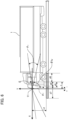
- FIG. 6 is a side view of the vehicle 1 when viewed from the side in the first embodiment.
- Fig. 7 is a front view of the vehicle 1 when viewed from the front, the front view illustrating a relationship between the camera unit 11 and the vehicle 1 in the first embodiment
- Fig. 8 is a plan view of the vehicle 8 when viewed from above, the plan view illustrating a specified region below the front surface of the vehicle in the first embodiment.
- the X, Y, and Z directions and angles in Figs. 6 to 8 correspond to those in Figs. 4A and 4B and Fig. 5 , respectively, and have the same relationship.
- E in Figs. 6 and 8 represents a viewpoint position of a driver, and a positional relationship (x, h1, z) between the camera unit 11 and the vehicle 1 and a relationship between the optical axis and an imaging angle of view ( ⁇ v, ⁇ v, ⁇ lv, cph, ⁇ h, ⁇ lh) in Figs. 6 and 7 have the same relationships as those in Figs. 4A and 4B .
- a specified region below the front surface of the vehicle will be described using Figs. 6 to 8 .
- the specified region below the front surface of the vehicle is a region that needs to be confirmed by the driver using a side under mirror of the vehicle.
- d7 is a distance from the tip end of the vehicle 1 to a distant front lower region to be confirmed
- d0 is a distance from the viewpoint position E to the tip end of the vehicle 1
- w6 is the vehicle width of the vehicle 1
- w7 is a distance to a distant region at the side of the vehicle to be confirmed.
- the specified region below the front surface of the vehicle is a region represented by a region on the ground surrounded by d7 and (w6 + w7).
- an installation condition under which the camera unit 11 can image a specified region in a downward direction ahead the vehicle 1 is a condition under which the region surrounded by d7 and (w6 + w7) is included in the imaging angle of view of the camera unit 11 (third condition).
- the camera unit is installed to satisfy the installation condition as the third condition (Equations 6 and 7) so that an angle of view of a front end of d7 is included in the imaging angle of view of the camera unit 11 ( ⁇ v - ⁇ v - ⁇ lv) to ( ⁇ v + ⁇ v + ⁇ lv).
- the camera unit 11 is installed to satisfy the installation condition (Equations 8 and 9) so that the ends of w6 and w7 are included in the range of (w6 + w7) within the imaging angle of view of the camera unit 11.
- Equations 8 and 9 the installation condition
- the ends of w6 and w7 are included in the range of (w6 + w7) within the imaging angle of view of the camera unit 11.
- the camera unit 11 can realize a movable apparatus capable of imaging a wide range of a predetermined specified region below the front of the vehicle with high resolution.
- all of the first, second, and third conditions described above may not be satisfied, and installing the camera unit to satisfy at least one of the first to third conditions described above is included.
- Fig. 9 is a plan view of the vehicle 1 when viewed from above, the plan view illustrating a specified region behind the vehicle side surface in the first embodiment. Regions on the ground on the sides and backward of the vehicle indicated by oblique lines in Fig. 9 are the same as the specified regions behind the vehicle side surfaces described in Fig. 5 .
- the specified wide regions behind the vehicle side surfaces are set to be regions (region3, region4) on the ground surface which are defined by a width W3 from the side surface of the vehicle body at a distance d3 from the driver's viewpoint position E to the backward and a width w4 from the side surface of the vehicle body at a distance d4 from the driver's viewpoint position E to the backward.
- the camera unit 11 disposed on the side of the passenger seat can cope with installation conditions for large-sized vehicles by being installed so that the specified wide region regions behind the vehicle side surface is included in the imaging range.
- the detection region is a region where there is a high possibility of trapping or a collision in a case where there is an object in the detection region, for example, when the host vehicle is turning left.
- the camera unit 11 disposed on the side of the passenger seat is installed such that the detection region is included in the imaging range, and thus it is also possible to meet the installation conditions for detecting a moving object on the side of the passenger seat.
- Fig. 10 is a schematic plan view of the vehicle 1 when viewed from above in order to describe the specified region on the side of the passenger seat of the vehicle in the first embodiment.
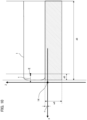
- Fig. 11 is a side view of the vehicle 1 when viewed from the side in the first embodiment.
- the X, Y, Z directions and angles in Figs. 10 and 11 have the same relationship as in Figs. 6 to 8 .
- E illustrated in Figs. 10 and 11 is the same as E illustrated in Figs. 6 to 8 , and represents the driver's viewpoint position.
- a specified region on the side surface on the side of the passenger seat of the vehicle is a region surrounded by a distance d8 from the front surface of the vehicle body to the backward side of the vehicle body where it is necessary to perform detection, and a distance w8 from the side surface of the vehicle body to a distant region at the side of the vehicle body where it is necessary to perform detection.
- a moving object having a size that needs to be detected is an object having a height h2.
- a detection region for a side collision warning is a region surrounded by the specified region on the side surface on the side of the passenger seat of the vehicle and the height h2.
- the camera unit 11 is installed such that the detection region for the side collision warning is included in the angle of view, and thus it is also possible to cope with installation conditions for large-sized vehicles.
- the height h1 of the camera unit 11 is preferably higher than the height h2 of the moving object to be detected. That is, it is desirable to satisfy the condition of the following Equation 10. h 1 ⁇ h 2
- the moving object having a height h2 can be included in the imaging range without widening the imaging angle of view of the camera unit as compared with the case of the condition of h1 ⁇ h2.
- h2 When a pedestrian is included in detection targets, it is desirable to set h2 to 2 meters.
- an offset x of the camera unit When an offset x of the camera unit is larger than the front end of the vehicle, it is necessary to include the entire ground in the region with a width w8 at that position in the imaging range in order to image the detection target within the detection region.
- the installation conditions for the camera unit 11 have been described above. It is desirable that the camera unit 11 be disposed diagonally ahead and outside the corner of the vehicle body on the side of the passenger seat in order to capture images with high resolution in a plurality of required imaging ranges and high resolution imaging directions using a smaller number of cameras.
- the camera unit 12 disposed on the driver's seat side is also installed under similar installation conditions, and thus images can be captured in a plurality of required imaging ranges and high resolution imaging directions with high resolution using a smaller number of cameras. It is desirable that the camera unit 12 be disposed diagonally ahead and outside the corner of the vehicle body on the driver's seat side.
- the driver be able to confirm these specified regions visually or using a mirror or a display device.
- a specific example in a case where the camera unit 11 in the first embodiment includes these ground regions in an imaging region will be described.
- the camera unit is installed such that an angle ⁇ v in the vertical direction and an angle cph in the horizontal direction of the optical axis of the camera unit are respectively -28.56° ⁇ ⁇ v ⁇ 0.0° and -30.0° ⁇ cph ⁇ 30.0° that are obtained from Equations 2 to 9 described above.
- the camera unit 11 in the first embodiment includes this region in an imaging region.
- a camera unit having a vertical angle of view ⁇ v and a horizontal angle of view ⁇ h being 23.6 degrees and a vertical angle of view ⁇ lv and a horizontal angle of view ⁇ lh being 66.4 degrees in the high resolution region 10a is used.
- the camera unit be installed such that the angle cph in the horizontal direction of the optical axis of the camera unit is set to -23.6° ⁇ cph ⁇ 0° obtained from Equations 4, 8, 9 and 10 described above.
- the specified region can be included in the imaging range of the high resolution region of the camera unit.
- the vertical angle of view ⁇ v and the horizontal angle of view ⁇ h of the high resolution region 10a of the camera unit which satisfies the conditions of Equations 2 and 3 may be determined based on this.
- a single camera can capture images of a plurality of specified regions and can also capture images in two or more horizontal directions with high resolution.
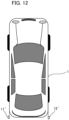
- Fig. 12 is a diagram illustrating a positional relationship between a camera unit and a vehicle in a second embodiment.
- a camera unit having optical characteristics as illustrated in Fig. 2 is installed at the rear corner of a vehicle 1 as illustrated in Fig. 12 .
- the second imaging device includes an optical system that forms an optical image, which has a low resolution region near the optical axis and a high resolution region outside a low resolution region, on a light receiving surface of an imaging element.
- an offset x between the camera unit 11 and the viewpoint position E of the driver is different, the same installation conditions can be used.
- the camera unit is installed to be able to capture an image of infinity, that is, in a horizontal direction with a width w2.
- the camera unit be installed to be able to capture images from the nearby ground to the horizontal direction with high resolution.
- the camera unit 11' is installed such that a region w1 separated from the viewpoint position E by d1 in addition to Equation 2 is included in an imaging angle of view so that the specified region region1 on the vehicle side surface is included in the angle of view of the camera unit 11'.
- the camera unit be installed to satisfy a condition 1 (Equations 2 and 3) as an installation example.
- an image is captured in the horizontal backward direction of one side surface of the vehicle 1 in the high resolution region of the optical system, and thus the camera unit 11' can capture an image in the horizontal direction with high resolution while imaging the specified region region1 on the side surface of the vehicle 1 in Fig. 5 .
- the installation conditions under which the camera unit 11' can capture an image in the horizontal direction with high resolution for display for a backward CTA will be described in detail.
- the display for the backward CTA it is required to be able to confirm an object approaching from a distant region in the right or the left direction at an intersection with poor visibility, and the camera unit 11' is required to be installed to be able to confirm the right or the left horizontal direction behind the viewpoint position E (driver's seat) of the driver.
- the camera unit 11' is located behind the viewpoint position E (x ⁇ 0) is considered.
- the camera unit 11' is installed such that the high resolution regions 10a in the right or the left direction ((cph - ⁇ h - ⁇ lh) to (cph - ⁇ lh) in the right direction when facing the front of the vehicle, (cph + ⁇ lh) to (cph + ⁇ h + ⁇ lh) in the left direction when facing the front of the vehicle) includes the right or the left horizontal direction.
- the camera unit 11' When the camera unit 11' is located ahead the viewpoint position E (x ⁇ 0), the camera unit 11' is installed such that a horizontal region behind the viewpoint position E is included in the high resolution region. With such installation, the camera unit 11' can image either one of the side surfaces of the vehicle in the horizontal direction with high resolution.
- the camera unit 11' be disposed at a position where the vehicle 1 is not imaged centering on the optical axis in order to image the backward of the vehicle in the right or the left direction and to image the backward of the side surface of the vehicle.
- an offset x of the camera unit be larger than the tip end of the rear surface of the vehicle 1 in order to image the backward of the vehicle in the right or the left direction.
- an offset z of the camera unit 11' be installed outside the side of the vehicle 1 (-Z direction in Fig. 4 ).
- Equations 2 and 3 and Equation 4 or Equation 5 By satisfying the conditions of Equations 2 and 3 and Equation 4 or Equation 5 as described above, either one of the backward of the side surface of the vehicle 1 and the right or the left direction can be included in the imaging angle of view. Further, it is desirable to satisfy the following fourth condition for including a downward direction behind the vehicle 1 within the imaging angle of view, in addition to the first condition of Equations 2 and 3 and the second condition of Equations 4 and 5 described above.
- the second embodiment may satisfy any one of the first condition, the second condition, and the fourth condition.
- Fig. 13 is a plan view of the vehicle 1 when viewed from above, the plan view illustrating a specified region below the front surface of the vehicle in the second embodiment.
- Fig. 13 The X, Y, and Z directions and angles in Fig. 13 correspond to those in Figs. 4A and 4B and Fig. 5 , respectively, and have the same relationship.
- E illustrated in Fig. 13 is the same as E illustrated in Fig. 4A and Fig. 5 , and represents the driver's viewpoint position.
- a positional relationship (x, h1, z) between the camera unit 11' and the vehicle 1 illustrated in Fig. 13 and a relationship between the optical axis and the imaging angle of view ( ⁇ v, ⁇ v, ⁇ lv, (ph, ⁇ h, ⁇ lh) are also the same relationships as those illustrated in Figs. 4A and 4B .
- d8 in Fig. 13 is the length (vehicle length) of the vehicle 1.
- the specified region below the backward surface of the vehicle is a region that needs to be confirmed by the driver with a display device when the vehicle is backing up, and it is assumed that d11 is a distance from a predetermined position on the front side to be confirmed, which is away from the backward surface of the vehicle by d10, to a predetermined distant position to be confirmed, and w6 is the vehicle width of the vehicle 1.
- the specified region below the backward surface of the vehicle is a region represented by a region on the ground surrounded by d11 and w6, and it is desirable that the camera unit 11' be able to image an object with a height h3 within a predetermined specified region to be confirmed behind the vehicle 1.
- the installation condition (fourth condition) under which the camera unit 11' can image the specified region below the backward surface of the vehicle is a condition that a region surrounded by d11, w6, and the height h3 is included in the imaging angle of view of the camera unit 11'.
- the camera unit 11' is installed to satisfy the following installation conditions (Equation 11, Equation 12, Equation 14) or installation conditions (Equation 11, Equation 13, and Equation 15) so that the above-described region is included within the imaging angle of view ( ⁇ v - ⁇ v - ⁇ lv) to ( ⁇ v + ⁇ v + ⁇ lv) of the camera unit 11'.
- z is a distance between the installation position (second installation position) of the camera unit 11' and the side surface of the vehicle.
- the camera unit 11' can appropriately image the specified region in a downward direction behind the vehicle. Particularly, in a large-sized vehicle, it is necessary to detect a moving object at the side of the passenger seat of the vehicle and image a detection region for a side collision warning to be given to the driver when there is a possibility of collision.
- the detection region is a region where there is a high possibility of trapping or a collision in a case where there is an object in the detection region, for example, when the host vehicle is turning left.
- the camera unit 11 disposed on the side of the passenger seat can also cope with an installation condition for detecting a moving object on the side of the passenger seat by installing the camera unit 11 so that the detection region is included within the imaging range.
- a relationship between the specified region at the side on the passenger seat side of the vehicle, the detection region, and the object is the same as those in Figs. 10 and 11 .
- description is given of an installation condition under which the camera unit 11' can capture images with a range having a width w5 and distance d5 illustrated in Figs. 6 and 8 under the side of the passenger seat of the vehicle as a specified region.
- Equation 16 it is desirable to satisfy the following installation condition (Equation 16) so that the above-described region is included in an imaging angle of view ( ⁇ v - ⁇ v - ⁇ lv to ⁇ v + ⁇ v + ⁇ lv) of the camera unit 11', in addition to Equations 8 and 10.
- Equation 16 it is desirable to satisfy the following installation condition (Equation 16) so that the above-described region is included in an imaging angle of view ( ⁇ v - ⁇ v - ⁇ lv to ⁇ v + ⁇ v + ⁇ lv) of the camera unit 11', in addition to Equations 8 and 10.
- Fig. 14 is a diagram illustrating a specified region behind a vehicle in the second embodiment, and the specified region behind the vehicle is a range having a width w12 and a distance d12 as illustrated in Fig. 14 .
- a width from the side surface of the vehicle to the specified region is defined as w11. Installation conditions under which the camera unit 11' can capture images will be described.
- the installation conditions for the camera unit 11' have been described above.
- the camera unit 11' be disposed diagonally behind and outside the corner behind the passenger seat side.
- a camera unit 12' disposed on the driver's seat side is also disposed under the same installation conditions, and thus images can be captured in a plurality of required imaging ranges and high resolution imaging directions on the driver's seat side with a smaller number of cameras than the number of directions required for high resolution imaging. It is desirable that the camera unit 12' be also disposed diagonally behind and outside the corner behind the driver's seat side.
- an angle ⁇ v in the vertical direction and an angle cph in the horizontal direction of the optical axis of the camera unit are respectively 22.2° ⁇ ⁇ v ⁇ 0° and -7.06° ⁇ cph ⁇ 9.14° obtained from Equations 2 to 5 and Equations 11 to 18 described above.
- the angle cph in the horizontal direction of the optical axis of the camera unit is set to -9.87° ⁇ cph ⁇ 0° obtained by Equations 4, 8, 10. 14, 15, and 18 described above.
- the specified region can be included in the imaging range of the high resolution region of the camera unit.
- the installation position (x, z, h) of the camera unit and the angle of the optical axis of the camera unit are determined in advance, the vertical angle of view ⁇ v and the horizontal angle of view ⁇ h of the high resolution region 10a of the camera unit which satisfies the conditions of Equations 2 and 3 may be determined based on this.
- a single camera can capture images of a plurality of specified regions and can also capture images in two or more horizontal directions with high resolution.
- a case where the camera unit having the optical characteristics as illustrated in Fig. 2 is disposed at the second installation position at the rear has been described, but camera unit may be combined with a camera unit disposed at the front as in the first embodiment.
- a total of four camera units including two camera units at both front corners and two camera units at both rear corners when the vehicle 1 is viewed from above may be disposed.
- a total of two camera units including one camera unit at the front corner on the passenger seat side and one camera unit at the rear corner on the driver's seat side, which is a diagonal position may be installed.
- two camera units may be disposed at the front corner, and one camera unit may be disposed at the rear corner, or one camera unit may be disposed at the front corner, and two camera units may be disposed at the rear corner.
- At least a portion of the information processing system of the embodiment may or may not be mounted on a movable apparatus such as a vehicle.
- the present invention can be applied to a case where a movable apparatus is remotely controlled.
- a computer program realizing the function of the embodiments described above may be supplied to the movable apparatus through a network or various storage media. Then, a computer (or a CPU, an MPU, or the like) of the movable apparatus may be configured to read and execute the program. in such a case, the program and the storage medium storing the program configure the present invention.
- the present invention includes, for example, realizing the functions of the embodiments explained above by using at least one processor or circuit.
- a plurality of processors may be used for distributed processing.
- a movable apparatus is configured such that a first imaging device is installed at a first installation position, the first imaging device including an optical system that forms an optical image, which has a low resolution region near an optical axis and a high resolution region outside the low resolution region, on a light receiving surface of an imaging element, and the first installation position being a position where an image is captured in at least one of a horizontal backward direction of one side surface of the movable apparatus, right or left direction in a horizontal direction ahead a driver's seat of the movable apparatus, and a downward direction ahead the movable apparatus in the high resolution region of the optical system.
Landscapes
- Engineering & Computer Science (AREA)
- Multimedia (AREA)
- Signal Processing (AREA)
- Theoretical Computer Science (AREA)
- Mechanical Engineering (AREA)
- Physics & Mathematics (AREA)
- General Physics & Mathematics (AREA)
- Computing Systems (AREA)
- Closed-Circuit Television Systems (AREA)
- Studio Devices (AREA)
Abstract
Description
- The present invention relates to a movable apparatus such as an automobile, and an installation method for an imaging device.
- In recent years, a camera monitor system (CMS) technology for replacing mirrors mounted on automobiles with electronic mirrors has been promoted. A plurality of imaging devices (cameras) installed for CMS may be installed to capture (image) images in all directions as eyes of an electronic system for securing safety.
- In addition, the UN regulations UN-R46 (regulations for indirect vision for automobiles) defines a driver's blind spots, and CMS is also required to perform imaging and to be installed so as to reduce blind spots, similar to existing mirrors.
- In addition, automobiles equipped with a cross traffic alert (CTA) function are respectively equipped with cameras capable of capturing images in right or left direction ahead and behind a vehicle with high resolution so as to be able to detect the approach of other vehicles crossing in front or to the backward of the vehicle.
- In addition, automobiles equipped with a forward or backward monitoring device (front monitor or back monitor) are each equipped with a wide-angle camera capable of capturing an image in a wide range ahead or behind a vehicle.
Japanese Patent No. 6349558 - However, the camera with high resolution in a portion of the imaging region used in
Japanese Patent No. 6349558 - In order to achieve the above-described object, a movable apparatus according to an aspect of the present invention is a movable apparatus including a first imaging device including an optical system that forms an optical image, which has a low resolution region near an optical axis and a high resolution region outside the low resolution region, on a light receiving surface of an imaging element, in which the first imaging device is installed at a first installation position where an image is captured in at least one of a horizontal backward direction of one side surface of the movable apparatus, right or left direction in a horizontal direction ahead a driver's seat of the movable apparatus, and a downward direction ahead the movable apparatus in the high resolution region of the optical system.
- Further features of the present invention will become apparent from the following description of embodiments with reference to the attached drawings.
-
-
Fig. 1 is a diagram illustrating a positional relationship between a camera unit and a vehicle in a first embodiment. -
Figs. 2A and 2B are diagrams illustrating optical characteristics of an optical system of acamera unit 11 in the first embodiment. -
Fig. 3 is a diagram illustrating animage processing system 100 in the first embodiment. -
Figs. 4A and 4B are diagrams illustrating a relationship between characteristics of the optical system of thecamera unit 11 installed in avehicle 1 in the first embodiment and an imaging region required for displaying an electronic side mirror and a front CTA. -
Fig. 5 is a plan view of thevehicle 1 of the first embodiment when viewed from above. -
Fig. 6 is a side view of thevehicle 1 of the first embodiment when viewed from the side. -
Fig. 7 is a front view of thevehicle 1 when viewed from the front, the front view illustrating a relationship between thecamera unit 11 and thevehicle 1 in the first embodiment. -
Fig. 8 is a plan view of thevehicle 1 when viewed from above, the plan view illustrating a specified region below a front surface of a vehicle in the first embodiment. -
Fig. 9 is a plan view of thevehicle 1 when viewed from above, the plan view illustrating specified regions behind the vehicle side surfaces in the first embodiment. -
Fig. 10 is a schematic plan view of thevehicle 1 when viewed from above, the plan view illustrating a specified region of the side surface of a passenger seat of the vehicle in the first embodiment. -
Fig. 11 is a side view of thevehicle 1 when viewed from the side in the first embodiment. -
Fig. 12 is a diagram illustrating a positional relationship between a camera unit and a vehicle in a second embodiment. -
Fig. 13 is a plan view of thevehicle 1 when viewed from above, the plan view illustrating a specified region below the front surface of the vehicle in the second embodiment. -
Fig. 14 is a diagram illustrating a specified region behind the vehicle in the second embodiment. - Hereinafter, with reference to the accompanying drawings, favorable modes of the present invention will be described using embodiments. In each diagram, the same reference signs are applied to the same members or elements, and duplicate description will be omitted or simplified.
- In a first embodiment, an installation method for a camera unit that captures high resolution videos for an electronic side mirror and a front CTA and also captures videos for a forward monitoring device will be described.
Fig. 1 is a diagram illustrating a positional relationship between a camera unit and a vehicle in the first embodiment. -
Fig. 1 is a diagram illustrating an example in which acamera unit 11 as a first imaging device is installed on the front left side of avehicle 1, which is an automobile, and acamera unit 12 is installed on the front right side. In the first embodiment, description is given on the assumption that two camera units are installed in avehicle 1, but the number of camera units is not limited to two, and at least one or more camera units may be provided. In addition, it is sufficient that a plurality of camera units capable of capturing images in a required imaging range and high resolution imaging direction can be installed. - The
camera units vehicle 1 from the side surfaces thereof in order to capture a video for an electronic side mirror, imaging at least one of the right and left sides of the forward direction of thevehicle 1 to be able to capture a video for a front CTA, and capturing forward and downward videos for a forward monitoring device of thevehicle 1. - Optical systems of the
camera units camera units Fig. 2 . -
Figs. 2A and 2B ) are diagrams illustrating optical characteristics of the optical system of thecamera unit 11 in the first embodiment.Fig. 2A is a contour line diagram illustrating an image circle of the optical system of thecamera unit 11 and an image height y at each half angle of view on a light receiving surface of an imaging element. -
Fig. 2B is a diagram illustrating projection characteristics of an image circle representing a relationship between an image height y of the optical system of thecamera unit 11 and a half angle of view θ. InFig. 2B , the half angle of view (an angle formed by the optical axis and an incident light beam) θ is shown as the horizontal axis, and an imaging height (image plane) y on a light receiving surface (image plane) of the imaging element of thecamera unit 11 is shown as the vertical axis. - As illustrated in
Fig. 2B , in the first embodiment, a configuration is adopted in which a projection characteristic y(θ) differs between a region with less than a predetermined half angle of view θa and a region with the half angle of view θa or more. When the amount of increase in the image height y with respect to the half angle of view θ per unit, that is, an index represented by a differential value dy(θ)/dθ of the projection characteristic y(θ) at the half angle of view θ is assumed to be a resolution, it can be said that the resolution increases as the inclination of the projection characteristic y(θ) inFig. 2B becomes larger. - It can be said that the larger an interval of the image height y at each half angle of view of the contour line in
Fig. 2A , the higher the resolution. In this manner, the optical system of thecamera unit 11 has an optical characteristic that the half angle of view is larger than the resolution of the region with a half angle of view less than θa in the region with the half angle of view θa or more. - It is assumed that the projection characteristics y(θ) of the optical system illustrated in
Figs. 2A and 2B satisfy, for example, a condition ofEquation 1, wherein f is a focal distance of the optical system.
- In the first embodiment, a region of a peripheral portion of the light receiving surface where a half angle of view θ is equal to or greater than θa is referred to as a
high resolution region 10a, and a region of the center of the light receiving surface where a half angle of view θ is less than θa is referred to as alow resolution region 10b. In other words, the optical system in the first embodiment has a projection characteristic that an image height with respect to an angle of view per unit in the angle of view in the high resolution region is higher than that the angle of view in the low resolution region in the vicinity of the optical axis. The optical system has a low resolution region in the vicinity of the optical axis and has a high resolution region outside the low resolution region. - In the first embodiment, a boundary circle between the
high resolution region 10a and thelow resolution region 10b is referred to as a resolution boundary, and a boundary image on a display screen corresponding to the resolution boundary is referred to as a display resolution boundary or simply a boundary image. However, the boundary between thehigh resolution region 10a and thelow resolution region 10b is not limited to a circular shape, and may be an ellipse having a different projection characteristic y(θ) for each radial direction, or a distorted shape. - In the first embodiment, a lens with the above-described characteristics is referred to as a stereoscopic projection lens, and a camera unit with a stereoscopic projection lens attached thereto is referred to as a stereoscopic projection camera.
- In the first embodiment, it is assumed that the center of gravity of the
low resolution region 10b and the center of gravity of thehigh resolution region 10a on the light receiving surface of the imaging element of the camera unit substantially overlap each other, and the center of gravity of thehigh resolution region 10a substantially matches a position where the optical axis of the optical system of the camera unit intersects the light receiving surface of the imaging element. - However, for example, the center of gravity of the light receiving surface of the imaging element and the center of gravity of the
high resolution region 10a may deviate from each other in a predetermined direction, and the center of gravity of thehigh resolution region 10a may deviate from the position where the optical axis of the optical system intersects the light receiving surface. - Next, a configuration of the image processing system in the present embodiment will be described using
Fig. 3. Fig. 3 is a diagram illustrating theimage processing system 100 in the first embodiment, and theimage processing system 100 ofFig. 3 is mounted on thevehicle 1. - The
camera unit 11 includes animaging unit 21 and acamera processing unit 31, and thecamera unit 12 includes animaging unit 22 and acamera processing unit 32. Theimaging units stereoscopic projection lenses imaging elements - The
stereoscopic projection lenses camera units Figs. 2A and 2B . Thestereoscopic projection lenses imaging elements - The
imaging elements imaging elements imaging unit 21 as imaging signals. - The
camera processing units imaging units camera processing units image processing units recognition units camera information units - A CPU as a computer and a memory storing a computer program as a storage medium are built into each of the
camera processing units camera processing units - The
camera processing units image processing units recognition units - The
image processing units imaging units image processing units low resolution region 10b and not to perform distortion correction on the image signal of thehigh resolution region 10a. - Further, for example, image data input from the
imaging units image processing system 100 other than theimage processing units - The
recognition units image processing units integrated processing unit 40. For example, the image recognition result is transmitted to theintegrated processing unit 40 as a recognition result including the type of object and a set of coordinates. - Further, the
recognition units integrated control unit 41c of theintegrated processing unit 40 and may perform image recognition processing. - The
camera information units camera units camera information units camera units - The stored camera information includes information such as characteristic information of the
stereoscopic projection lenses imaging elements camera units camera processing unit 31. - The mounting position information of the camera unit is stored in the memory in the camera information unit in advance as relative coordinates with respect to the
vehicle 1 because the mounting position with respect to the vehicle is often determined for each camera unit. The camera information may be information unique to theimaging units 21 and 22 (for example, lens aberration characteristics, noise characteristics of the imaging elements, and the like). The camera information is transmitted to theintegrated processing unit 40 and is referred to when theintegrated processing unit 40 performs necessary image processing or the like in order to display the camera information on a display unit. - The
integrated processing unit 40 has a function of displaying video signals obtained from thecamera units first display unit 50 and asecond display unit 51, and a function of notifying awarning display unit 52 and avoice notification unit 53 of the video signals. Further, theintegrated processing unit 40 has an image recognition function for an object straddling boundaries of imaging ranges of thecamera units - The
integrated processing unit 40 includes a system on chip (SOC) / field programable gate array (FPGA) 41, aCPU 42 as a computer, and amemory 43 as a storage medium. In the first embodiment, description is given on the assumption that theintegrated processing unit 40 is accommodated in a housing separate from the camera unit. - Some or all of the functional blocks included in the
integrated processing unit 40 and the like may be implemented by hardware or may be implemented by theCPU 42. As the hardware, a dedicated circuit (ASIC), a processor (reconfigurable processor, DSP), or the like can be used. TheCPU 42 performs various controls of the entireimage processing system 100 by executing computer programs stored in thememory 43. - The SOC /
FPGA 41 includes animage processing unit 41a, arecognition unit 41b, and anintegrated control unit 41c. Theimage processing unit 41a has a function of performing image processing such as resolution conversion for display on a display device based on the image signals and camera information acquired from thecamera processing units - As described above, the camera information includes optical characteristics of the
stereoscopic projection lenses imaging elements - For example, the
image processing unit 41a synthesizes the distortion-corrected image signal of thelow resolution region 10b of each of theimaging units high resolution region 10a so that the image signals are smoothly connected, thereby forming an overall image for each of theimaging units image processing unit 41a performs image processing such as image rotation based on the camera information, particularly the arrangement position and orientation information of the camera, and transmits an image signal to the display device. - The
recognition unit 41b performs image recognition processing on a synthesized image obtained by connecting images from theimaging units imaging units - At that time, the recognition results (the type and coordinates of the object) obtained by the
recognition units recognition unit 41b performs image recognition on the synthesized image obtained from theimaging units - Description will be continued on the assumption that the
recognition unit 41b can output a second image recognition result as a result of image recognition performed on an image signal in a region wider than a partial region in which image recognition is performed by the first image recognition unit among image signals acquired by an image acquisition unit. - The
integrated control unit 41c functions as an integrated processing unit that outputs an image recognition result integrated based on the reliability of the first image recognition result and the reliability of the second image recognition result. For example, when the recognition result of therecognition units recognition unit 41b are different from each other, theintegrated control unit 41c outputs an image recognition result integrated by adopting a recognition result with higher reliability. - For example, the proportion of an object in an image recognized by the
recognition units recognition unit 41b in a screen, and a recognition result with a higher proportion is determined to have high reliability and is adopted. - The
integrated control unit 41c has a function of forming a video signal for displaying a desired image on thefirst display unit 50, thesecond display unit 51, or the like from an image-processed entire image for each of theimaging units - Further, a CG of a boundary image for displaying a boundary may be generated based on characteristic information of the optical system such as display resolution boundary information acquired from the
camera information units first display unit 50, thesecond display unit 51, and the like display image signals and integrated image recognition results. - Further, the
integrated control unit 41c communicates with a running control unit (ECU) 60 and the like via a communication unit, which is not illustrated in the drawing, provided therein by using protocols such as CAN, FlexRay, and Ethernet. - Accordingly, display processing for appropriately changing information to be displayed based on a vehicle control signal received from the running control unit (ECU) 60 or the like is performed. That is, for example, the range of an image to be displayed on the display unit, and the like can be changed in accordance with a moving state of a vehicle which is acquired in response to the vehicle control signal.
- The traveling control unit (ECU) 60 is a unit that is mounted on the
vehicle 1 and includes a computer and memory for comprehensively performing drive control, direction control, and the like of thevehicle 1. From the running control unit (ECU) 60, information on the running (movement state) of the vehicle such as a running speed, a running direction, a shift lever, a shift gear, the state of a turn signal, the orientation of the vehicle obtained by a geomagnetic sensor or the like, and GPS information, and the like are input to theintegrated processing unit 40 as vehicle control signals. - Further, the
integrated control unit 41c may have a function of transmitting information such as the type, position, moving direction, moving speed, and the like of a predetermined object (such as an obstacle or the like) which are recognized by therecognition unit 41b to the running control unit (ECU) 60. - Thereby, the running control unit (ECU) 60 performs control necessary for avoiding obstacles such as stopping the vehicle, driving the vehicle, and changing the direction of travel. The running control unit (ECU) 60 functions as a movement control unit that controls the movement of the vehicle based on an integrated image recognition result.
- The
first display unit 50 is a display device that is installed, for example, near the center of an upper portion ahead a driver's seat of thevehicle 1 in the vehicle width direction with a display screen directed toward the backward of the vehicle and function as an electronic rearview mirror. Thefirst display unit 50 may be configured to be usable as a mirror when it is not used as a display by using a half mirror or the like. - Further, the
first display unit 50 includes a touch panel and operation buttons and may be configured to acquire instructions from the user and output them to theintegrated control unit 41c. Thefirst display unit 50 can also be used as an electronic side mirror for confirming obstacles or the like on the right or left, as a display device displaying a video for front CTA instead of, for example, an optical side mirror of the related art. - The
first display unit 50 receives and displays a video signal generated by theintegrated control unit 41c and having an angle of view required for display in accordance with the application of the first display unit. - The
second display unit 51 is a display device that is installed, for example, in the vicinity of an operation panel near the center ahead the driver's seat of thevehicle 1 in the vehicle width direction and functions as a display device for displaying, for example, a region in a lower direction ahead the vehicle. Similarly to the first display unit, thesecond display unit 51 also functions as a display device that receives a necessary imaging region generated in accordance with the application. Theintegrated control unit 41c receives and displays signals necessary for display in accordance with the application of the second display unit. - For example, the second display unit can display various control signals received from a navigation system, an audio system, and the running control unit (ECU) 60. The second display unit includes a touch panel and operation buttons and may be configured to be able to acquire instructions from the user.
- The
second display unit 51 may be, for example, a display unit of a tablet terminal, and can also display an image by being connected to theintegrated processing unit 40 in a wired manner and can also receive and display an image through acommunication unit 62 in a wireless manner. A liquid crystal display, an organic EL display, or the like can be used as display elements of thefirst display unit 50 and thesecond display unit 51, and the number of display units is not limited to one. - The
integrated control unit 41c determines whether a moving object is included in an image based on recognition results output by therecognition units recognition unit 41b, and outputs the recognition results. Here, the moving object here is, for example, a bicycle, a pedestrian, and other vehicles, and are referred to as a detection target in the first embodiment. The recognition results output by theintegrated control unit 41c include whether there is a detection target, the type and coordinates of a detection target, and speed information. - Based on the recognition result output from the
integrated control unit 41c, thewarning display unit 52 issues, for example, a side collision warning to the driver by using visual information. Thewarning display unit 52 may be constituted by, for example, an LED, and may be configured to perform lighting or blinking when the recognition result includes information indicating that there is a detection target. - The
warning display unit 52 may be constituted by a display such as a liquid crystal. In this case, when the recognition result includes information indicating that there is a detection target, an icon, character information, or the like is output to the display. Further, thewarning display unit 52 can be installed, for example, in the vicinity of an end ahead the driver's seat of thevehicle 1 in the vehicle width direction with the display screen directed toward the driver. - The
warning display unit 52 may be installed, for example, near thefirst display unit 50 and thesecond display unit 51, or may be configured to be replaced with thefirst display unit 50 and thesecond display unit 51. Thevoice notification unit 53 outputs a sound based on the recognition result output from theintegrated control unit 41c. For example, the driver can be notified of a sound by outputting the sound using a speaker. It is desirable to install, for example, thevoice notification unit 53 near an end ahead the driver's seat of thevehicle 1 in the vehicle width direction. - The
integrated control unit 41c also functions as a warning condition determination unit and performs control so that the content of a warning output by thewarning display unit 52 or thevoice notification unit 53 is changed based on the coordinates and speed of the detection target obtained by therecognition units 31b to 32b and therecognition unit 41b. Theintegrated control unit 41c may be configured to control thewarning display unit 52 so that the smaller a distance to the detection target is, the higher the degree of warning is. - For example, it is desirable to control the
voice notification unit 53 so that the smaller a distance to the detection target at the side of the vehicle is, the larger the sound volume of a notification is. Theintegrated control unit 41c may be configured to determine whether the running speed of the host vehicle which is input from the running control unit (ECU) 60 is equal to or less than a predetermined value, and to display a warning on thewarning display unit 52 or give a warning notification by thevoice notification unit 53 only when the running speed is the predetermined value or less. - When the running speed of the host vehicle is high, there is a possibility that the detection target cannot be correctly recognized. Thus, with such a configuration, the possibility of performing correct side detection can be improved. At this time, it is desirable to set the predetermined value of the running speed of the host vehicle to 30 km/hkm/h.
- When the detection target is moving compared to when it is stopped, there is a stronger possibility of the detection target colliding with the vehicle. Thus, the
integrated control unit 41c may be configured to determine whether the speed of the detection target is within a predetermined range, and to display a warning on thewarning display unit 52 or give a warning notification by thevoice notification unit 53 only when it is determined that the speed of the detection target is within the predetermined range. In this case, it is desirable to set a predetermined range of the speed of a predetermined detection target to 5 km/h or more and 20 km/h or less. - Further, the
integrated control unit 41c determines whether the vehicle is turning right or left based on moving direction information of the host vehicle which is output from the running control unit (ECU) 60, and displays a warning on thewarning display unit 52 or give a warning notification by thevoice notification unit 53 only when the vehicle is turning right or left. - Although the
integrated processing unit 40 is mounted on thevehicle 1 in the first embodiment, some of the processing of theimage processing unit 41a, therecognition unit 41b, and theintegrated control unit 41c of theintegrated processing unit 40 may be performed by an external server or the like via, for example, a network. - In this case, for example, the
imaging units 21 to 24 as image acquisition units are mounted on thevehicle 1, but for example, some of the functions of thecamera processing units integrated processing unit 40 can be processed by an external server or the like. In addition, it is possible to make the running control unit (ECU) 60 have some or all of the functions of theintegrated processing unit 40. -
Reference numeral 61 denotes a storage unit, and the entire image for each of theimaging units integrated processing unit 40 is recorded. Further, a CG such as a predetermined frame, characters, and a warning indicating a recognized object, and images having the CG superimposed thereon and displayed on thefirst display unit 50, thesecond display unit 51, and the like are recorded together with time, GPS information, and the like. Theintegrated processing unit 40 can also reproduce past information recorded in thestorage unit 61 and display it on thefirst display unit 50 and thesecond display unit 51. - The
communication unit 62, which is a unit for communicating with an external server or the like via a network, can transmit information before being recorded in thestorage unit 61 and past running history information and the like recorded in thestorage unit 61 to an external server or the like and store them in the external server or the like. - As described above, an image can be transmitted to an external tablet terminal or the like and displayed on the
second display unit 51, which is a display unit of the tablet terminal. Traffic congestion information and various types of information can be acquired from an external server or the like and displayed on thefirst display unit 50 and thesecond display unit 51 via theintegrated processing unit 40. -
Reference numeral 63 denotes an operation unit for inputting various instructions to the image processing system by a user's operation. The operation unit includes, for example, a touch panel, operation buttons, and the like. - Next, a relationship between characteristics and arrangement of the
camera unit 11 installed on the left front side and thecamera unit 12 installed on the right front side will be described.Figs. 4A and 4B are diagrams illustrating a relationship between characteristics of the optical system of thecamera unit 11 installed in thevehicle 1 in the first embodiment and an imaging region required for display for an electronic side mirror and a front CTA.Fig. 4A is a side view of thevehicle 1 when viewed from the side, andFig. 4B is a front view of the vehicle when viewed from the front. - The origin of the X, Y, and Z directions in
Fig. 4 is the installation position of thecamera unit 11, and the X direction is a forward direction of the vehicle in the horizontal direction as illustrated inFig. 4A . The Z direction is a left direction in the horizontal direction when facing thevehicle 1 as illustrated inFig. 4B . The Y direction is an upward direction in the vertical direction as illustrated inFigs. 4A and 4B . - In the XY plane in
Fig. 4A , a positive angle is set in the X direction and a negative angle is set in the -X direction with reference to the vertical direction. In the YZ plane inFig. 4B , a positive angle is set in the Z direction and a negative angle is set in the -Z direction with reference to the vertical direction. E in the XY plane inFig. 4A represents the driver's viewpoint position, which is the eye position of the driver at a seated position or the center position on the driver's seat surface. - A relationship between the optical axis of the
camera unit 11 and an imaging angle of view will be described using the above-described definition, ϕv, θv, and θlv in the XY plane inFig. 4A will be described. ϕv is the optical axis direction of thecamera unit 11 and is an angle from the vertical direction. In the first embodiment, the optical axis of the imaging device is directed downward from an installation position. - θv is an angle of view of the
high resolution region 10a of thecamera unit 11. θlv is an angle of view of thelow resolution region 10b of thecamera unit 11. - cph, θh, and θlh in the YZ plane in
Fig. 4B will be described. cph is the optical axis direction of thecamera unit 11 and is an angle from the vertical direction. θh is an angle of view of thehigh resolution region 10a of thecamera unit 11. θlh is an angle of view of thelow resolution region 10b of thecamera unit 11. - A positional relationship of the
camera unit 11 will be described using the above-described definition, x in the XY plane inFig. 4A is a horizontal distance between thecamera unit 11 and a viewpoint position E of the driver. h1 is a vertical distance between thecamera unit 11 and the ground. - z in the YZ plane in
Fig. 4B is a distance between the installation position (first installation position) of thecamera unit 11 and the side surface of thevehicle 1. Here, an imaging region (specified region behind the vehicle side surface) required for display of an electronic side mirror will be described with reference toFigs. 4 and5 . -
Fig. 5 is a top plan view of thevehicle 1 in the first embodiment, and the X and Z directions correspond to those inFig. 4 with the installation position of thecamera unit 11 as the origin. Specified regions behind the vehicle side surfaces are regions on the ground as indicated by hatching inFig. 4A andFig. 5 , and are regions that need to be confirmed by the driver with the side mirror of the vehicle. - The specified regions behind the vehicle side surfaces are regions on the ground surface defined by a width w1 from the side surface of the vehicle body at a distance d1 from the driver's viewpoint position E to the backward side and a width w2 from the side surface of the vehicle body at a distance d2, and a region on the passenger seat side is assumed to be region1, and a region on the driver's seat side is assumed to be region2. Here, region1 and region2 have shapes line-symmetrical to the longitudinal centerline of the
vehicle 1. - Installation conditions under which the
camera unit 11 installed on the side of the passenger seat can capture an image in the horizontal direction with high resolution while imaging the specified region region1 behind the vehicle side surface will be described. Since a distant region of region1, which is a specified region behind the vehicle side surface, extends to infinity behind the vehicle, thecamera unit 11 is installed to be able to capture an image of infinity, that is, the width w2 in the horizontal direction. In order to confirm a distant object away from the driver with a video captured by the camera, it is desirable to install the camera so that it can capture images with high resolution from the nearby ground direction to the horizontal direction. - Thus, in the first embodiment, the camera is installed to satisfy the following installation conditions (Equation 2) so that a horizontal angle (-90°) is included in the
high resolution region 10a (ϕv - θv - θlv) and the range of (angle of ϕv - θlv) of thecamera unit 11.
- A tip region (region of the width w1) in the moving direction of the specified region region1 at a position separated backward by d1 from the viewpoint position E in addition to Equation 2 is installed to be included in an imaging angle of view so that the specified region region1 on the side surface of the vehicle is included in an imaging angle of view of the
camera unit 11. - That is, the camera unit is installed to satisfy the following condition (Equation 3) that an angle (-Atan((x + d1) / h)) in the direction of the tip region of region1, which is separated backward by d1 from the viewpoint position E, is included in the angle of view (ϕv - θv - θlv) to (ϕv + θv + θlv) of the
camera unit 11.

- By installing the
camera unit 11 so as to satisfy the installation condition (first condition) of the above-describedEquations 2 and 3, thecamera unit 11 can capture an image in the horizontal direction with high resolution while imaging the specified region region1 behind one side surface of thevehicle 1. Here, one side surface of thevehicle 1 is the side surface on the side of the passenger seat. - Next, the installation conditions under which the
camera unit 11 can capture an image in the horizontal direction with high resolution for display for a front CTA will be described. It is desirable that the display for the front CTA be displayed so that an object approaching from a distant region in the right or the left direction can be confirmed at an intersection with poor visibility. Thus, in the first embodiment, thecamera unit 11 is installed so that the right or left of a horizontal directions ahead of the driver's viewpoint position E can be appropriately confirmed. - In other words, a distant region in the right or the left in the horizontal direction extends to infinity, and thus the camera unit is installed to be able to image nearby objects and far objects in the horizontal direction with high resolution. Here, an example of an installation condition (Equations 4 and 5) as a second condition under which the
camera unit 11 can capture images in at least one of the right and left in the horizontal direction ahead of the driver's viewpoint position E (driver's seat) will be described. - In the first embodiment, when the
camera unit 11 is ahead the viewpoint position E (x ≥ 0), thecamera unit 11 is installed to satisfy Equation 4 or Equation 5 as the following installation condition (second condition). That is, thehigh resolution regions 10a in the right or the left direction ((cph - θh - θlh) to (cph - θlh) in the right direction when facing the front of the vehicle, and (cph + θlh) to (cph + θh + θlh) in the left direction when facing the front of the vehicle) includes the right or the left horizontal direction.


- When the
camera unit 11 is behind the viewpoint position E (x < 0), it is desirable that thecamera unit 11 be installed such that a horizontal region ahead the viewpoint position E is included in a high resolution region. By installing thecamera unit 11 in this manner, thecamera unit 11 can image either one of the side surfaces of the vehicle in the horizontal direction with high resolution. - It is desirable that the
camera unit 11 be disposed at a position where thevehicle 1 is not imaged centering on the optical axis in order to image the front surface of the vehicle in the right or the left direction and to image the backward of the side surface of the vehicle. For example, it is desirable that an offset x of the camera unit be larger than a distance d0 from the viewpoint position E to the front tip end of thevehicle 1 in order to image the front side of the vehicle in the right or the left direction. - Further, in order to image the backward of the vehicle side surface, it is desirable that an offset z of the
camera unit 11 be installed outside the side of the vehicle 1 (-Z direction inFig. 4 ). - By satisfying the first condition of
Equations 2 and 3 and the second condition of Equations 4 and 5 in this manner, either the backward of the side surface and the right or the left direction of thevehicle 1 can be included in an imaging angle of view. Further, in order to include a region below the front of the vehicle within the imaging angle of view, it is desirable that the optical axis be directed toward the ground in addition to the conditions ofEquations 2 and 3 and Equations 4 and 5 described above. - An imaging region (a specified region below the front surface of the vehicle) necessary for forward lower display used for a forward monitoring device will be described with reference to
Figs. 6 to 8 .Fig. 6 is a side view of thevehicle 1 when viewed from the side in the first embodiment. -
Fig. 7 is a front view of thevehicle 1 when viewed from the front, the front view illustrating a relationship between thecamera unit 11 and thevehicle 1 in the first embodiment, andFig. 8 is a plan view of thevehicle 8 when viewed from above, the plan view illustrating a specified region below the front surface of the vehicle in the first embodiment. The X, Y, and Z directions and angles inFigs. 6 to 8 correspond to those inFigs. 4A and 4B andFig. 5 , respectively, and have the same relationship. - E in
Figs. 6 and8 represents a viewpoint position of a driver, and a positional relationship (x, h1, z) between thecamera unit 11 and thevehicle 1 and a relationship between the optical axis and an imaging angle of view (ϕv, θv, θlv, cph, θh, θlh) inFigs. 6 and7 have the same relationships as those inFigs. 4A and 4B . Here, a specified region below the front surface of the vehicle will be described usingFigs. 6 to 8 . - The specified region below the front surface of the vehicle is a region that needs to be confirmed by the driver using a side under mirror of the vehicle. Here, d7 is a distance from the tip end of the
vehicle 1 to a distant front lower region to be confirmed, d0 is a distance from the viewpoint position E to the tip end of thevehicle 1, w6 is the vehicle width of thevehicle 1, and w7 is a distance to a distant region at the side of the vehicle to be confirmed. - That is, the specified region below the front surface of the vehicle is a region represented by a region on the ground surrounded by d7 and (w6 + w7). Thus, an installation condition under which the
camera unit 11 can image a specified region in a downward direction ahead thevehicle 1 is a condition under which the region surrounded by d7 and (w6 + w7) is included in the imaging angle of view of the camera unit 11 (third condition). - Thus, in the first embodiment, the camera unit is installed to satisfy the installation condition as the third condition (Equations 6 and 7) so that an angle of view of a front end of d7 is included in the imaging angle of view of the camera unit 11 (ϕv - θv - θlv) to (ϕv + θv + θlv).


- In addition, the
camera unit 11 is installed to satisfy the installation condition (Equations 8 and 9) so that the ends of w6 and w7 are included in the range of (w6 + w7) within the imaging angle of view of thecamera unit 11.

- In the first embodiment, by installing the imaging device by such an installation method, the
camera unit 11 can realize a movable apparatus capable of imaging a wide range of a predetermined specified region below the front of the vehicle with high resolution. In the first embodiment, all of the first, second, and third conditions described above may not be satisfied, and installing the camera unit to satisfy at least one of the first to third conditions described above is included. - In addition, for large-sized vehicles, it is possible to confirm the field of view in a wider range than the specified region behind the vehicle side surface (a specified wide region behind the vehicle side surface). The specified side region behind the vehicle side surface will be described with reference to
Fig. 9. Fig. 9 is a plan view of thevehicle 1 when viewed from above, the plan view illustrating a specified region behind the vehicle side surface in the first embodiment. Regions on the ground on the sides and backward of the vehicle indicated by oblique lines inFig. 9 are the same as the specified regions behind the vehicle side surfaces described inFig. 5 . - The specified wide regions behind the vehicle side surfaces are set to be regions (region3, region4) on the ground surface which are defined by a width W3 from the side surface of the vehicle body at a distance d3 from the driver's viewpoint position E to the backward and a width w4 from the side surface of the vehicle body at a distance d4 from the driver's viewpoint position E to the backward. The
camera unit 11 disposed on the side of the passenger seat can cope with installation conditions for large-sized vehicles by being installed so that the specified wide region regions behind the vehicle side surface is included in the imaging range. - Particularly, in a large-sized vehicle, it is necessary to detect a moving object on the side of the passenger seat of the vehicle and image a detection region for a side collision warning to be given to a driver when there is a possibility of collision. The detection region is a region where there is a high possibility of trapping or a collision in a case where there is an object in the detection region, for example, when the host vehicle is turning left.
- The
camera unit 11 disposed on the side of the passenger seat is installed such that the detection region is included in the imaging range, and thus it is also possible to meet the installation conditions for detecting a moving object on the side of the passenger seat. - A relationship between the specified region on the side of the passenger seat of the vehicle, the detection region, and the object will be described using
Figs. 10 and11 .Fig. 10 is a schematic plan view of thevehicle 1 when viewed from above in order to describe the specified region on the side of the passenger seat of the vehicle in the first embodiment. -
Fig. 11 is a side view of thevehicle 1 when viewed from the side in the first embodiment. The X, Y, Z directions and angles inFigs. 10 and11 have the same relationship as inFigs. 6 to 8 . E illustrated inFigs. 10 and11 is the same as E illustrated inFigs. 6 to 8 , and represents the driver's viewpoint position. - As illustrated in
Fig. 10 , a specified region on the side surface on the side of the passenger seat of the vehicle is a region surrounded by a distance d8 from the front surface of the vehicle body to the backward side of the vehicle body where it is necessary to perform detection, and a distance w8 from the side surface of the vehicle body to a distant region at the side of the vehicle body where it is necessary to perform detection. A moving object having a size that needs to be detected is an object having a height h2. Thus, a detection region for a side collision warning is a region surrounded by the specified region on the side surface on the side of the passenger seat of the vehicle and the height h2. - The
camera unit 11 is installed such that the detection region for the side collision warning is included in the angle of view, and thus it is also possible to cope with installation conditions for large-sized vehicles. The height h1 of thecamera unit 11 is preferably higher than the height h2 of the moving object to be detected. That is, it is desirable to satisfy the condition of the following Equation 10.
- With such installation conditions, the moving object having a height h2 can be included in the imaging range without widening the imaging angle of view of the camera unit as compared with the case of the condition of h1 ≤ h2. For example, when a bicycle is included in detection targets, it is desirable to set h2 to 1.7 meters.
- When a pedestrian is included in detection targets, it is desirable to set h2 to 2 meters. When an offset x of the camera unit is larger than the front end of the vehicle, it is necessary to include the entire ground in the region with a width w8 at that position in the imaging range in order to image the detection target within the detection region.
- The installation conditions for the
camera unit 11 have been described above. It is desirable that thecamera unit 11 be disposed diagonally ahead and outside the corner of the vehicle body on the side of the passenger seat in order to capture images with high resolution in a plurality of required imaging ranges and high resolution imaging directions using a smaller number of cameras. - The installation conditions for the
camera unit 11 on the side of the passenger seat have been described. However, thecamera unit 12 disposed on the driver's seat side is also installed under similar installation conditions, and thus images can be captured in a plurality of required imaging ranges and high resolution imaging directions with high resolution using a smaller number of cameras. It is desirable that thecamera unit 12 be disposed diagonally ahead and outside the corner of the vehicle body on the driver's seat side. - Hereinafter, the
camera unit 11 installed ahead the passenger seat will be described with actual specific values. For example, description will be given of a case where a vehicle is a passenger car with nine passengers or less or a small freight car (for example, a vehicle weight is 3.5 tons or less) and d0 = 0.8 m. - In UN-R46, specified regions behind the vehicle side surfaces are defined as d1 = 4 m, d2 = 20 m, w1 = 1 m, and w2 = 4 m. In UN-R46, a specified region below the vehicle front surface is defined as d7 = 0.3 m, w6 = 1.8 m, and w7 = 0.3 m. In addition, d7 = 2.3 m, d8 = 4.8 m, and w8 = 0.3 are defined in the safety standards established by the Ministry of Land, Infrastructure, Transport and Tourism (ground region as specified in Article 27 of Article 21 (driver's seat) of the Road Transport Vehicle Safety Standards and Attachment 29).
- It is desirable that the driver be able to confirm these specified regions visually or using a mirror or a display device. A specific example in a case where the
camera unit 11 in the first embodiment includes these ground regions in an imaging region will be described. - For example, a case is assumed in which a camera unit having a vertical angle of view θv and a horizontal angle of view θh being 30.0 degrees, and a vertical angle of view θlv and a horizontal angle of view θlh being 60 degrees in the
high resolution region 10a is installed at a position where x = 0.8 m, z = 0.3 m, and h = 1.2 m. In this case, it is only required that the camera unit is installed such that an angle ϕv in the vertical direction and an angle cph in the horizontal direction of the optical axis of the camera unit are respectively -28.56° < ϕv < 0.0° and -30.0° < cph < 30.0° that are obtained from Equations 2 to 9 described above. - For example, in the case of a large-sized freight vehicle with a total vehicle weight of 8.0 tons or more, it is desirable to be able to confirm more regions. Thus, it is desirable that the driver be able to confirm a specified region of d0 = 1.0 m, d1 = 4 m, d2 = 30 m, d3 = 1.5 m, d4 = 10 m, d5 = 1 m, d6 = 1.75 m, d7 = 2 m, d8 = 12 m, w1 = 1 m, w2 = 5 m, w3 = 4.5 m, w4 = 15 m, w5 = 2 m, w6 = 2 m, w7 = 2 m, and w8 = 3 m, that are obtained similarly, visually or using a mirror or a display device.
- A specific example in which the
camera unit 11 in the first embodiment includes this region in an imaging region will be described. For example, a camera unit having a vertical angle of view θv and a horizontal angle of view θh being 23.6 degrees and a vertical angle of view θlv and a horizontal angle of view θlh being 66.4 degrees in thehigh resolution region 10a is used. Then, it is only required that the camera unit is installed at a position of x = 1.2 m, z = 0.3 m, and h = 2.3 m so that an angle ϕv in the vertical direction of the optical axis of the camera unit is set to -23.6° < ϕv < 0.0° obtained fromEquations 2, 3, 6, 7, and 10 described above. - Since it is desirable that the horizontal direction in the left direction be included in an angle of view in order to image the backward of the side surface at a wide angle, it is desirable that the camera unit be installed such that the angle cph in the horizontal direction of the optical axis of the camera unit is set to -23.6° < cph < 0° obtained from
Equations 4, 8, 9 and 10 described above. - In the above-described numerical example, conditions for an angle of the optical axis of the camera unit in that case have been calculated with the installation position (x, z, h) of the camera unit as a fixed condition, but it is only required that the conditions of
Equations 2 and 3 are satisfied, and a method of calculating the installation conditions is not limited thereto. For example, when an angle of the optical axis of the camera unit is determined in advance as a vehicle design constraint, the range of an installation position of the camera unit which satisfies the conditions ofEquations 2 and 3 is determined based on this. - Thereby, the specified region can be included in the imaging range of the high resolution region of the camera unit. Similarly, when the installation position (x, z, h) of the camera unit and the angle of the optical axis of the camera unit are determined in advance, the vertical angle of view θv and the horizontal angle of view θh of the
high resolution region 10a of the camera unit which satisfies the conditions ofEquations 2 and 3 may be determined based on this. As described above, a single camera can capture images of a plurality of specified regions and can also capture images in two or more horizontal directions with high resolution. -
Fig. 12 is a diagram illustrating a positional relationship between a camera unit and a vehicle in a second embodiment. In the second embodiment, a camera unit having optical characteristics as illustrated inFig. 2 is installed at the rear corner of avehicle 1 as illustrated inFig. 12 . - In the second embodiment, description is given of an installation method for a camera that can capture images in a plurality of required imaging ranges and high resolution imaging directions with fewer cameras than the number of directions required for high resolution imaging when the backward and lateral sides are imaged. Description of the portions that have been already described in the first embodiment is omitted.
- First, installation conditions under which a camera unit 11' as a second imaging device installed at the rear corner of the
vehicle 1 can image a specified region region1 behind the vehicle side surface in the same manner as in the first embodiment will be described. It is assumed that the camera unit 11' has substantially the same optical system, imaging device characteristics, and the like as those of thecamera unit 11 described in the first embodiment. - That is, the second imaging device includes an optical system that forms an optical image, which has a low resolution region near the optical axis and a high resolution region outside a low resolution region, on a light receiving surface of an imaging element. Although an offset x between the
camera unit 11 and the viewpoint position E of the driver is different, the same installation conditions can be used. - That is, since the distance of a specified region behind the vehicle side surface extends to infinity behind the vehicle, the camera unit is installed to be able to capture an image of infinity, that is, in a horizontal direction with a width w2. In order to confirm an object far away from the driver with a video captured by the camera, it is desirable that the camera unit be installed to be able to capture images from the nearby ground to the horizontal direction with high resolution.
- The camera unit 11' is installed such that a region w1 separated from the viewpoint position E by d1 in addition to Equation 2 is included in an imaging angle of view so that the specified region region1 on the vehicle side surface is included in the angle of view of the camera unit 11'. Thus, it is desirable that the camera unit be installed to satisfy a condition 1 (Equations 2 and 3) as an installation example.
- That is, an image is captured in the horizontal backward direction of one side surface of the
vehicle 1 in the high resolution region of the optical system, and thus the camera unit 11' can capture an image in the horizontal direction with high resolution while imaging the specified region region1 on the side surface of thevehicle 1 inFig. 5 . - The installation conditions under which the camera unit 11' can capture an image in the horizontal direction with high resolution for display for a backward CTA will be described in detail. In the display for the backward CTA, it is required to be able to confirm an object approaching from a distant region in the right or the left direction at an intersection with poor visibility, and the camera unit 11' is required to be installed to be able to confirm the right or the left horizontal direction behind the viewpoint position E (driver's seat) of the driver.
- Since distant regions in the right or the left horizontal direction continue to infinity, it is desirable to install the camera unit so that it can image nearby objects in the horizontal direction with high resolution. An example of an installation condition (Equations 4 and 5) under which the camera unit 11' can capture an image in at least one of the right or the left horizontal direction behind the driver's viewpoint position E will be described.
- A case where the camera unit 11' is located behind the viewpoint position E (x < 0) is considered. In this case, the camera unit 11' is installed such that the
high resolution regions 10a in the right or the left direction ((cph - θh - θlh) to (cph - θlh) in the right direction when facing the front of the vehicle, (cph + θlh) to (cph + θh + θlh) in the left direction when facing the front of the vehicle) includes the right or the left horizontal direction. - When the camera unit 11' is located ahead the viewpoint position E (x ≥ 0), the camera unit 11' is installed such that a horizontal region behind the viewpoint position E is included in the high resolution region. With such installation, the camera unit 11' can image either one of the side surfaces of the vehicle in the horizontal direction with high resolution.
- It is desirable that the camera unit 11' be disposed at a position where the
vehicle 1 is not imaged centering on the optical axis in order to image the backward of the vehicle in the right or the left direction and to image the backward of the side surface of the vehicle. For example, it is desirable that an offset x of the camera unit be larger than the tip end of the rear surface of thevehicle 1 in order to image the backward of the vehicle in the right or the left direction. Further, in order to image the backward of the side of the vehicle, it is desirable that an offset z of the camera unit 11' be installed outside the side of the vehicle 1 (-Z direction inFig. 4 ). - By satisfying the conditions of
Equations 2 and 3 and Equation 4 or Equation 5 as described above, either one of the backward of the side surface of thevehicle 1 and the right or the left direction can be included in the imaging angle of view. Further, it is desirable to satisfy the following fourth condition for including a downward direction behind thevehicle 1 within the imaging angle of view, in addition to the first condition ofEquations 2 and 3 and the second condition of Equations 4 and 5 described above. - However, the second embodiment may satisfy any one of the first condition, the second condition, and the fourth condition.
- An imaging region (a specified region below the backward surface of the vehicle) necessary for display for a lower backward side which is used for a backward monitoring device will be described using
Fig. 13. Fig. 13 is a plan view of thevehicle 1 when viewed from above, the plan view illustrating a specified region below the front surface of the vehicle in the second embodiment. - The X, Y, and Z directions and angles in
Fig. 13 correspond to those inFigs. 4A and 4B andFig. 5 , respectively, and have the same relationship. E illustrated inFig. 13 is the same as E illustrated inFig. 4A andFig. 5 , and represents the driver's viewpoint position. - A positional relationship (x, h1, z) between the camera unit 11' and the
vehicle 1 illustrated inFig. 13 and a relationship between the optical axis and the imaging angle of view (ϕv, θv, θlv, (ph, θh, θlh) are also the same relationships as those illustrated inFigs. 4A and 4B . d8 inFig. 13 is the length (vehicle length) of thevehicle 1. - Here, a specified region below the backward surface of the vehicle will be described with reference to
Fig. 13 . The specified region below the backward surface of the vehicle is a region that needs to be confirmed by the driver with a display device when the vehicle is backing up, and it is assumed that d11 is a distance from a predetermined position on the front side to be confirmed, which is away from the backward surface of the vehicle by d10, to a predetermined distant position to be confirmed, and w6 is the vehicle width of thevehicle 1. - In this case, the specified region below the backward surface of the vehicle is a region represented by a region on the ground surrounded by d11 and w6, and it is desirable that the camera unit 11' be able to image an object with a height h3 within a predetermined specified region to be confirmed behind the
vehicle 1. - Thus, the installation condition (fourth condition) under which the camera unit 11' can image the specified region below the backward surface of the vehicle is a condition that a region surrounded by d11, w6, and the height h3 is included in the imaging angle of view of the camera unit 11'.
- That is, the camera unit 11' is installed to satisfy the following installation conditions (
Equation 11,Equation 12, Equation 14) or installation conditions (Equation 11, Equation 13, and Equation 15) so that the above-described region is included within the imaging angle of view (ϕv - θv - θlv) to (ϕv + θv + θlv) of the camera unit 11'. Note that z is a distance between the installation position (second installation position) of the camera unit 11' and the side surface of the vehicle.

(when h1 ≥ h3)
(when h1 < h3)
(when h1 ≥ h3)
(when h1 < h3)
- With such installation, the camera unit 11' can appropriately image the specified region in a downward direction behind the vehicle. Particularly, in a large-sized vehicle, it is necessary to detect a moving object at the side of the passenger seat of the vehicle and image a detection region for a side collision warning to be given to the driver when there is a possibility of collision.
- The detection region is a region where there is a high possibility of trapping or a collision in a case where there is an object in the detection region, for example, when the host vehicle is turning left. The
camera unit 11 disposed on the side of the passenger seat can also cope with an installation condition for detecting a moving object on the side of the passenger seat by installing thecamera unit 11 so that the detection region is included within the imaging range. - A relationship between the specified region at the side on the passenger seat side of the vehicle, the detection region, and the object is the same as those in
Figs. 10 and11 . Here, description is given of an installation condition under which the camera unit 11' can capture images with a range having a width w5 and distance d5 illustrated inFigs. 6 and8 under the side of the passenger seat of the vehicle as a specified region. - For example, it is desirable to satisfy the following installation condition (Equation 16) so that the above-described region is included in an imaging angle of view (ϕv - θv - θlv to ϕv + θv + θlv) of the camera unit 11', in addition to
Equations 8 and 10.

- Since it is necessary to display a video of a distant region behind the vehicle on a display unit in order for the driver to confirm the backward of the vehicle using an electronic rearview mirror, it is desirable to image a specified region behind the vehicle in a high resolution region so as to be able to confirm a distant region.
-
Fig. 14 is a diagram illustrating a specified region behind a vehicle in the second embodiment, and the specified region behind the vehicle is a range having a width w12 and a distance d12 as illustrated inFig. 14 . A width from the side surface of the vehicle to the specified region is defined as w11. Installation conditions under which the camera unit 11' can capture images will be described. - In order to image the specified region, it is desirable to satisfy an installation condition (Equations 17 and 18) so that, for example, the above-described region is included within the imaging angle of view (ϕv - θv - θlv) to (ϕv + θv + θlv) of the camera unit 11'.


- The installation conditions for the camera unit 11' have been described above. In order to capture images in a plurality of required imaging ranges and high resolution imaging directions with a smaller number of cameras than the number of directions required for high resolution imaging, it is desirable that the camera unit 11' be disposed diagonally behind and outside the corner behind the passenger seat side.
- The installation conditions for the camera unit 11' on the passenger seat side have been described above. A camera unit 12' disposed on the driver's seat side is also disposed under the same installation conditions, and thus images can be captured in a plurality of required imaging ranges and high resolution imaging directions on the driver's seat side with a smaller number of cameras than the number of directions required for high resolution imaging. It is desirable that the camera unit 12' be also disposed diagonally behind and outside the corner behind the driver's seat side.
- Actual specific numerical values for the camera unit 11' on the passenger seat side will be described below. For example, in the case of a passenger car with nine passengers or less or a small freight vehicle (for example, a vehicle weight of 3.5 tons or less), it is desirable that the driver be able to confirm a specified region in which d0 = 0.9 m, d1 = 4, d2 = 20 m, d8 = 4.8 m, d10 = 0.3 m, d11 = 3.5 m, d12 = 60 m, w1 = 1 m, w2 = 4 m, w5 = 0.3 m, w6 = 1.8 m, w11 = 9 m, w12 = 20 m by using an electronic side mirror.
- In this case, for example, when a camera unit having a vertical angle of view θv and a horizontal angle of view θh of 23.6 degrees and a vertical angle of view θlv and a horizontal angle of view θlh of 66.4 degrees in the
high resolution region 10a is used and installed at a position where x = 3 m, z = 0.3 m, and h = 1.4 m, an angle ϕv in the vertical direction and an angle cph in the horizontal direction of the optical axis of the camera unit are respectively 22.2° < ϕv <0° and -7.06° < cph < 9.14° obtained from Equations 2 to 5 andEquations 11 to 18 described above. - For example, in the case of a large-sized freight vehicle with a total vehicle weight of 8.0 tons or more, it is desirable to be able to confirm more regions. Thus, it is desirable that the driver be able to confirm a specified region of d0 = 1 m, d1 = 4 m, d3 = 1.5 m, d4 = 10 m, d5 = 1 m, d6 = 1.75 m, d7 = 2 m, d8 = 12 m, d10 = 0.3 m, d11 = 3.5 m, d12 = 60 m, w1 = 1 m, w2 = 5 m, w3 = 4.5 m, w4 = 15 m, w5 = 2 m, w8 = 3 m, w6 = 2 m, w11 = 9 m, and w12 = 20 m using an electronic side mirror.
- In this case, it is assumed that a camera unit having a vertical angle of view θv and a horizontal angle of view θh being 23.6 degrees and a vertical angle of view θlv and a horizontal angle of view θlh being 66.4 degrees in the
high resolution region 10a is used and installed at a position where x = 12 m, z = 0.2 m, and h = 2 m. Then, an angle ϕv in the vertical direction of the optical axis of the camera unit is -8.75° < ϕv <0° obtained byEquations - Since it is desirable that the horizontal direction in the left direction be included in an angle of view in order to image the backward of the side surface at a wide angle, the angle cph in the horizontal direction of the optical axis of the camera unit is set to -9.87°< cph <0° obtained by
Equations 4, 8, 10. 14, 15, and 18 described above. - In the above-described numerical example, conditions for an angle of the optical axis of the camera unit in that case have been calculated with the installation position (x, z, h) of the camera unit as a fixed condition, but it is only required that the conditions of
Equations 2 and 3 are satisfied, and a method of calculating the installation conditions is not limited thereto. For example, when an angle of the optical axis of the camera unit is determined in advance as a vehicle design constraint, the range of an installation position of the camera unit which satisfies the conditions ofEquations 2 and 3 is determined based on this. - Thereby, the specified region can be included in the imaging range of the high resolution region of the camera unit. Similarly, when the installation position (x, z, h) of the camera unit and the angle of the optical axis of the camera unit are determined in advance, the vertical angle of view θv and the horizontal angle of view θh of the
high resolution region 10a of the camera unit which satisfies the conditions ofEquations 2 and 3 may be determined based on this. - As described above, also in the second embodiment, a single camera can capture images of a plurality of specified regions and can also capture images in two or more horizontal directions with high resolution. In the second embodiment, a case where the camera unit having the optical characteristics as illustrated in
Fig. 2 is disposed at the second installation position at the rear has been described, but camera unit may be combined with a camera unit disposed at the front as in the first embodiment. - That is, for example, a total of four camera units including two camera units at both front corners and two camera units at both rear corners when the
vehicle 1 is viewed from above may be disposed. Alternatively, for example, a total of two camera units including one camera unit at the front corner on the passenger seat side and one camera unit at the rear corner on the driver's seat side, which is a diagonal position, may be installed. Alternatively, two camera units may be disposed at the front corner, and one camera unit may be disposed at the rear corner, or one camera unit may be disposed at the front corner, and two camera units may be disposed at the rear corner. - At least a portion of the information processing system of the embodiment may or may not be mounted on a movable apparatus such as a vehicle. The present invention can be applied to a case where a movable apparatus is remotely controlled.
- While the present invention has been described with reference to exemplary embodiments, it is to be understood that the invention is not limited to the disclosed exemplary embodiments. The scope of the following claims is to be accorded the broadest interpretation to encompass all such modifications and equivalent structures and functions.
- In addition, as a part or the whole of the control according to the embodiments, a computer program realizing the function of the embodiments described above may be supplied to the movable apparatus through a network or various storage media. Then, a computer (or a CPU, an MPU, or the like) of the movable apparatus may be configured to read and execute the program. in such a case, the program and the storage medium storing the program configure the present invention.
- The present invention includes, for example, realizing the functions of the embodiments explained above by using at least one processor or circuit. A plurality of processors may be used for distributed processing.
- This application claims the benefit of
Japanese patent application no. 2022-157151, filed on September 29, 2022 - In order to dispose an imaging device so that it can image a wide range with high resolution, a movable apparatus is configured such that a first imaging device is installed at a first installation position, the first imaging device including an optical system that forms an optical image, which has a low resolution region near an optical axis and a high resolution region outside the low resolution region, on a light receiving surface of an imaging element, and the first installation position being a position where an image is captured in at least one of a horizontal backward direction of one side surface of the movable apparatus, right or left direction in a horizontal direction ahead a driver's seat of the movable apparatus, and a downward direction ahead the movable apparatus in the high resolution region of the optical system.
Claims (13)
- A movable apparatus comprising:a first imaging device including an optical system that forms an optical image, which has a low resolution region near an optical axis and a high resolution region outside the low resolution region, on a light receiving surface of an imaging element,wherein the first imaging device is installed at a first installation position where an image is captured in at least one of a horizontal backward direction of one side surface of the movable apparatus, right or left direction in a horizontal direction ahead of a driver's seat of the movable apparatus, and a downward direction ahead of the movable apparatus in the high resolution region of the optical system.
- The movable apparatus according to claim 1, wherein the optical system has a projection characteristic in which an image height with respect to an angle of view per unit is higher at an angle of view in the high resolution region than at an angle of view in the low resolution region near the optical axis.
- The movable apparatus according to claim 1, wherein an optical axis direction of the optical system is downward from the first installation position.
- The movable apparatus according to claim 1, wherein, when the image height of the optical system is y, f is a focal distance of the optical system, and θ is a half angle of view, a projection characteristic y(θ) satisfies the following condition of 0.2 < 2 * ftan(θmax / 2) / y(θmax) < 0.92.
- The movable apparatus according to claim 1, wherein the one side surface of the movable apparatus is a side surface on a passenger seat side of the movable apparatus.
- The movable apparatus according to claim 1, wherein, when an angle in an optical axis direction from a vertical direction when the movable apparatus is viewed from the side surface is ϕv, an angle of view of the high resolution region is θv, an angle of view of the low resolution region is θlv, a predetermined distance from a driver's viewpoint position to a backward side is d1, a distance between the viewpoint position and the first installation position is x, and a height of the first installation position is h1, the following equations are satisfied.


- The movable apparatus according to claim 1, wherein, when an angle in an optical axis direction from a vertical direction when the movable apparatus is viewed from the front is cph, an angle of view of the high resolution region is θh, and an angle of view of the low resolution region is θlh, the following equations are satisfied.


- The movable apparatus according to claim 1, wherein, when an angle in an optical axis direction from a vertical direction when the movable apparatus is viewed from the side surface is ϕv, an angle of view of the high resolution region is θv, an angle of view of the low resolution region is θlv, a predetermined distance from a driver's viewpoint position to a backward side is d1, a distance between the viewpoint position and the first installation position is x, a height of the first installation position is h1, a distance between the viewpoint position and a tip end of the movable apparatus is d0, and a distance from the tip end of the movable apparatus to a predetermined front lower position to be confirmed is d7, the following equations are satisfied.


- The movable apparatus according to claim 8, wherein, when a vehicle width of the movable apparatus is w6, a distance to be confirmed at the side of the movable apparatus is w7, and a distance between the first installation position and the side surface of the movable apparatus is z, the following equations are satisfied.


- The movable apparatus according to claim 1, wherein a second imaging device having the same characteristics as the first imaging device is disposed at a second installation position diagonally opposite to the first installation position when the movable apparatus is viewed from above, and
an image is captured in at least one of a horizontal direction behind one side surface of the movable apparatus, one of right and left direction in a horizontal direction behind the driver's seat of the movable apparatus, and a downward direction behind the movable apparatus in the high resolution region of the optical system. - The movable apparatus according to claim 10, wherein, for the second imaging device, when an angle in an optical axis direction from a vertical direction when the movable apparatus is viewed from the side surface is ϕv, an angle of view of the high resolution region is θv, an angle of view of the low resolution region is θlv, a distance between a driver's viewpoint position and the second installation position is x, a height of the second installation position is h1, a distance from the viewpoint position and a tip end of the movable apparatus is d0, a length of the movable apparatus is d8, a distance from the movable apparatus to a predetermined position on the front side to be confirmed behind the movable apparatus is d10, a distance from the movable apparatus to a predetermined distant position to be confirmed behind the movable apparatus is d11, a width of the movable apparatus is w6, a height of an object to be confirmed behind the movable apparatus is h3, and a distance between the second installation position and the side surface of the movable apparatus is z, the following equations are satisfied.




- A movable apparatus comprising:a first imaging device including an optical system that forms an optical image, which has a low resolution region near an optical axis and a high resolution region outside the low resolution region, on a light receiving surface of an imaging element,wherein the high resolution region of the optical system is installed at a first installation position that satisfies at least one of the following first, second, and third conditions,the first condition being a condition that the following equations are satisfied

 when an angle in an optical axis direction from a vertical direction when the movable apparatus is viewed from the side surface is ϕv, an angle of view of the high resolution region is θv, an angle of view of the low resolution region is θlv, a predetermined distance from a driver's viewpoint position to a backward side is d1, a distance between the viewpoint position and the first installation position is x, and a height of the first installation position is h1,the second condition is a condition that satisfies the following equations
 when an angle in an optical axis direction from a vertical direction when the movable apparatus is viewed from the front is cph, an angle of view of the high resolution region is θh, and an angle of view of the low resolution region is θlh, andthe third condition is a condition that satisfies the following equations
 when a distance between the viewpoint position and a tip end of the movable apparatus is d0, and a distance from the tip end of the movable apparatus to a predetermined front lower position to be confirmed is d7.
 - An installation method for an imaging device, the installation method comprising:
installing a first imaging device at a first installation position, the first imaging device including an optical system that forms an optical image, which has a low resolution region near an optical axis and a high resolution region outside the low resolution region, on a light receiving surface of an imaging element, and the first installation position being a position where an image is captured in at least one of a horizontal backward direction of one side surface of the movable apparatus, right or left direction in a horizontal direction ahead a driver's seat of the movable apparatus, and a downward direction ahead the movable apparatus in the high resolution region of the optical system.
Applications Claiming Priority (1)
| Application Number | Priority Date | Filing Date | Title |
|---|---|---|---|
| JP2022157151A JP2024050334A (en) | 2022-09-29 | 2022-09-29 | Mobile body and imaging device installation method |
Publications (1)
| Publication Number | Publication Date |
|---|---|
| EP4344952A1 true EP4344952A1 (en) | 2024-04-03 |
Family
ID=88192346
Family Applications (1)
| Application Number | Title | Priority Date | Filing Date |
|---|---|---|---|
| EP23199068.0A Withdrawn EP4344952A1 (en) | 2022-09-29 | 2023-09-22 | Movable apparatus and installation method for imaging device |
Country Status (4)
| Country | Link |
|---|---|
| US (1) | US12470839B2 (en) |
| EP (1) | EP4344952A1 (en) |
| JP (1) | JP2024050334A (en) |
| CN (1) | CN117774832A (en) |
Families Citing this family (1)
| Publication number | Priority date | Publication date | Assignee | Title |
|---|---|---|---|---|
| JP7631275B2 (en) * | 2022-09-29 | 2025-02-18 | キヤノン株式会社 | Mobile body and imaging device installation method |
Citations (4)
| Publication number | Priority date | Publication date | Assignee | Title |
|---|---|---|---|---|
| US7605856B2 (en) * | 2003-09-08 | 2009-10-20 | Autonetworks Technologies, Ltd. | Camera unit and apparatus for monitoring vehicle periphery |
| JP6349558B1 (en) | 2017-05-12 | 2018-07-04 | パナソニックIpマネジメント株式会社 | Imaging system and display system |
| JP2022157151A (en) | 2021-03-31 | 2022-10-14 | トヨタ自動車株式会社 | Vehicular air conditioner |
| WO2023276819A1 (en) * | 2021-06-29 | 2023-01-05 | キヤノン株式会社 | Imaging system |
Family Cites Families (12)
| Publication number | Priority date | Publication date | Assignee | Title |
|---|---|---|---|---|
| JP5036891B2 (en) * | 2003-09-08 | 2012-09-26 | 株式会社オートネットワーク技術研究所 | Camera device and vehicle periphery monitoring device mounted on vehicle |
| JP6343629B2 (en) * | 2016-04-19 | 2018-06-13 | 富士通株式会社 | Display control apparatus, display control method, and display control program |
| JP7266165B2 (en) * | 2017-12-19 | 2023-04-28 | パナソニックIpマネジメント株式会社 | Imaging device, imaging system, and display system |
| JP6857147B2 (en) * | 2018-03-15 | 2021-04-14 | 株式会社日立製作所 | 3D image processing device and 3D image processing method |
| EP3886431A4 (en) * | 2018-11-22 | 2021-12-22 | Sony Semiconductor Solutions Corporation | IMAGE PROCESSING DEVICE, CAMERA SYSTEM AND IMAGE PROCESSING METHOD |
| CN109407279B (en) * | 2018-12-12 | 2021-09-14 | 江西联创电子有限公司 | Wide-angle lens and imaging apparatus |
| CN113330731A (en) * | 2019-01-23 | 2021-08-31 | 索尼半导体解决方案公司 | Vehicle-mounted camera |
| JP2020164067A (en) * | 2019-03-29 | 2020-10-08 | 5Kサポート株式会社 | Dashboard camera installation method, dashboard camera, and automobile |
| JP7400705B2 (en) * | 2020-11-30 | 2023-12-19 | トヨタ自動車株式会社 | Imaging system and imaging device |
| KR20230000505A (en) * | 2021-06-24 | 2023-01-03 | 현대자동차주식회사 | Vehicle and method for controlling thereof |
| JP2023178051A (en) | 2022-06-03 | 2023-12-14 | キヤノン株式会社 | Mobile object, method of controlling the mobile object, and computer program |
| JP7631275B2 (en) | 2022-09-29 | 2025-02-18 | キヤノン株式会社 | Mobile body and imaging device installation method |
-
2022
- 2022-09-29 JP JP2022157151A patent/JP2024050334A/en active Pending
-
2023
- 2023-09-22 US US18/472,278 patent/US12470839B2/en active Active
- 2023-09-22 EP EP23199068.0A patent/EP4344952A1/en not_active Withdrawn
- 2023-09-28 CN CN202311273535.1A patent/CN117774832A/en not_active Withdrawn
Patent Citations (4)
| Publication number | Priority date | Publication date | Assignee | Title |
|---|---|---|---|---|
| US7605856B2 (en) * | 2003-09-08 | 2009-10-20 | Autonetworks Technologies, Ltd. | Camera unit and apparatus for monitoring vehicle periphery |
| JP6349558B1 (en) | 2017-05-12 | 2018-07-04 | パナソニックIpマネジメント株式会社 | Imaging system and display system |
| JP2022157151A (en) | 2021-03-31 | 2022-10-14 | トヨタ自動車株式会社 | Vehicular air conditioner |
| WO2023276819A1 (en) * | 2021-06-29 | 2023-01-05 | キヤノン株式会社 | Imaging system |
Also Published As
| Publication number | Publication date |
|---|---|
| CN117774832A (en) | 2024-03-29 |
| US12470839B2 (en) | 2025-11-11 |
| US20240114252A1 (en) | 2024-04-04 |
| JP2024050334A (en) | 2024-04-10 |
Similar Documents
| Publication | Publication Date | Title |
|---|---|---|
| EP4344953A1 (en) | Movable apparatus and installation method for imaging device | |
| US12214733B2 (en) | Camera unit installing method, moving device, image processing system, image processing method, and storage medium | |
| US12165419B2 (en) | Movable apparatus, control method for movable apparatus, and storage medium | |
| US12325361B2 (en) | Mobile object, image processing method, and storage medium | |
| US12417642B2 (en) | System to integrate high distortion wide-angle camera recognition with low distortion normal-angle camera recognition | |
| US12387455B2 (en) | Image processing system, mobile object, image processing method, and storage medium, with output of image recognition result integrtated on basis of first result regarding image recognition on at least partial region and second result regarding image recognition on wider region | |
| US12530904B2 (en) | Image processing system, image processing method, and storage medium | |
| EP4395356A1 (en) | Image capturing device, movable apparatus, and storage medium | |
| US12028603B2 (en) | Image processing system, image processing method, storage medium, image pickup apparatus, and optical unit | |
| US11377027B2 (en) | Image processing apparatus, imaging apparatus, driving assistance apparatus, mobile body, and image processing method | |
| US20240259671A1 (en) | Image processing system, movable apparatus, image processing method, and storage medium | |
| EP4344952A1 (en) | Movable apparatus and installation method for imaging device | |
| US20250071232A1 (en) | Imaging apparatus and imaging system | |
| EP4431996A1 (en) | Movable apparatus, image processing apparatus, storage medium, and installation method for imaging apparatus | |
| EP4563414A1 (en) | Movable apparatus |
Legal Events
| Date | Code | Title | Description |
|---|---|---|---|
| PUAI | Public reference made under article 153(3) epc to a published international application that has entered the european phase |
Free format text: ORIGINAL CODE: 0009012 |
|
| STAA | Information on the status of an ep patent application or granted ep patent |
Free format text: STATUS: THE APPLICATION HAS BEEN PUBLISHED |
|
| AK | Designated contracting states |
Kind code of ref document: A1 Designated state(s): AL AT BE BG CH CY CZ DE DK EE ES FI FR GB GR HR HU IE IS IT LI LT LU LV MC ME MK MT NL NO PL PT RO RS SE SI SK SM TR |
|
| STAA | Information on the status of an ep patent application or granted ep patent |
Free format text: STATUS: REQUEST FOR EXAMINATION WAS MADE |
|
| 17P | Request for examination filed |
Effective date: 20241004 |
|
| RBV | Designated contracting states (corrected) |
Designated state(s): AL AT BE BG CH CY CZ DE DK EE ES FI FR GB GR HR HU IE IS IT LI LT LU LV MC ME MK MT NL NO PL PT RO RS SE SI SK SM TR |
|
| STAA | Information on the status of an ep patent application or granted ep patent |
Free format text: STATUS: THE APPLICATION HAS BEEN WITHDRAWN |
|
| 18W | Application withdrawn |
Effective date: 20250929 |