EP4344915A1 - An air intake device - Google Patents
An air intake device Download PDFInfo
- Publication number
- EP4344915A1 EP4344915A1 EP22198356.2A EP22198356A EP4344915A1 EP 4344915 A1 EP4344915 A1 EP 4344915A1 EP 22198356 A EP22198356 A EP 22198356A EP 4344915 A1 EP4344915 A1 EP 4344915A1
- Authority
- EP
- European Patent Office
- Prior art keywords
- air
- drainage container
- intake device
- air intake
- outlet
- Prior art date
- Legal status (The legal status is an assumption and is not a legal conclusion. Google has not performed a legal analysis and makes no representation as to the accuracy of the status listed.)
- Granted
Links
Images



Classifications
-
- B—PERFORMING OPERATIONS; TRANSPORTING
- B60—VEHICLES IN GENERAL
- B60H—ARRANGEMENTS OF HEATING, COOLING, VENTILATING OR OTHER AIR-TREATING DEVICES SPECIALLY ADAPTED FOR PASSENGER OR GOODS SPACES OF VEHICLES
- B60H1/00—Heating, cooling or ventilating devices
- B60H1/32—Cooling devices
- B60H1/3233—Cooling devices characterised by condensed liquid drainage means
-
- B—PERFORMING OPERATIONS; TRANSPORTING
- B60—VEHICLES IN GENERAL
- B60H—ARRANGEMENTS OF HEATING, COOLING, VENTILATING OR OTHER AIR-TREATING DEVICES SPECIALLY ADAPTED FOR PASSENGER OR GOODS SPACES OF VEHICLES
- B60H1/00—Heating, cooling or ventilating devices
- B60H1/00007—Combined heating, ventilating, or cooling devices
- B60H1/00021—Air flow details of HVAC devices
- B60H1/00028—Constructional lay-out of the devices in the vehicle
-
- B—PERFORMING OPERATIONS; TRANSPORTING
- B60—VEHICLES IN GENERAL
- B60H—ARRANGEMENTS OF HEATING, COOLING, VENTILATING OR OTHER AIR-TREATING DEVICES SPECIALLY ADAPTED FOR PASSENGER OR GOODS SPACES OF VEHICLES
- B60H1/00—Heating, cooling or ventilating devices
- B60H1/00507—Details, e.g. mounting arrangements, desaeration devices
- B60H1/00557—Details of ducts or cables
- B60H1/00564—Details of ducts or cables of air ducts
-
- B—PERFORMING OPERATIONS; TRANSPORTING
- B60—VEHICLES IN GENERAL
- B60H—ARRANGEMENTS OF HEATING, COOLING, VENTILATING OR OTHER AIR-TREATING DEVICES SPECIALLY ADAPTED FOR PASSENGER OR GOODS SPACES OF VEHICLES
- B60H1/00—Heating, cooling or ventilating devices
- B60H1/24—Ventilating devices where the heating or cooling is irrelevant
- B60H1/26—Ventilating openings in vehicle exterior; Ducts for conveying ventilating air
-
- B—PERFORMING OPERATIONS; TRANSPORTING
- B60—VEHICLES IN GENERAL
- B60H—ARRANGEMENTS OF HEATING, COOLING, VENTILATING OR OTHER AIR-TREATING DEVICES SPECIALLY ADAPTED FOR PASSENGER OR GOODS SPACES OF VEHICLES
- B60H1/00—Heating, cooling or ventilating devices
- B60H1/24—Ventilating devices where the heating or cooling is irrelevant
- B60H1/26—Ventilating openings in vehicle exterior; Ducts for conveying ventilating air
- B60H1/28—Ventilating openings in vehicle exterior; Ducts for conveying ventilating air the openings being situated directly in front of vehicle front window
-
- B—PERFORMING OPERATIONS; TRANSPORTING
- B60—VEHICLES IN GENERAL
- B60H—ARRANGEMENTS OF HEATING, COOLING, VENTILATING OR OTHER AIR-TREATING DEVICES SPECIALLY ADAPTED FOR PASSENGER OR GOODS SPACES OF VEHICLES
- B60H1/00—Heating, cooling or ventilating devices
- B60H1/00007—Combined heating, ventilating, or cooling devices
- B60H1/00021—Air flow details of HVAC devices
- B60H2001/00078—Assembling, manufacturing or layout details
- B60H2001/00085—Assembling, manufacturing or layout details of air intake
Definitions
- the invention relates to an air intake device and a vehicle.
- HVAC Heating Ventilation Air Conditioning
- any water, such as rainwater, in the air reaching the air intake device has to be separated from the air before providing the air to the HVAC system, and on the other hand, any means for removing the water should not cause air pressure drops in the air intake device that will negatively affect the performance of the HVAC system.
- An objective of the invention is to provide an air intake device for providing air to an air conditioning system of a vehicle, by which air intake device, water can be removed at the same time as the air pressure drop is kept to a minimum not adversely affecting the air conditioning system.
- an air intake device for providing air to an air conditioning system of a vehicle, wherein the air intake device comprises a collecting component with an opening for receiving air, a duct arranged for transporting air from the collecting component to the air conditioning system, and a drainage container, wherein the duct has a first duct part extending from the collecting component to an inlet of the drainage container, allowing air to flow from the collecting component and into the drainage container, and a second duct part extending from an outlet of the drainage container to the air conditioning system, allowing air to flow out from the drainage container and to the air conditioning system, and wherein the inlet and the outlet are arranged such that an airflow direction of the inlet and an airflow direction of the outlet form an angle ⁇ in the interval 90° ⁇ 270° relative to each other, thereby redirecting an airflow in the drainage container.
- the invention is based on the insight that by such an air intake device, water can be removed in an efficient way while minimizing the air pressure drop. Any water in the air flowing through the drainage container will be separated from the air in the drainage container.
- the drainage container preferably has a water drainage valve arranged in the bottom of the drainage container for removing the water collected in the drainage container.
- the angle ⁇ is in the interval 140° ⁇ 220°, preferably in the interval 160° ⁇ 200°, and more preferably in the interval 170° ⁇ 190°.
- the airflow direction of the inlet and the airflow direction of the outlet are the main directions of the airflow directed into the drainage container and out from the drainage container, respectively.
- the airflow direction of the outlet is substantially opposite to the airflow direction of the inlet.
- ⁇ is substantially 180° and the air will be redirected 180° when passing through the drainage container.
- the outlet is arranged above the inlet.
- the air is forced to flow upward before leaving the drainage container, and thereby, due to gravity, water is separated from the airflow.
- the air intake device has a pipe portion arranged at the outlet inside the drainage container, which pipe portion encloses the outlet, and preferably the pipe portion is an end portion of the second duct part, which end portion extends into the drainage container and ends inside the drainage container.
- the pipe portion is an end portion of the second duct part, which end portion extends into the drainage container and ends inside the drainage container.
- the inlet and the outlet are arranged on one and the same side of the drainage container.
- the first duct part has at least one internal guiding vane arranged to counteract swirling of the air before entering the drainage container.
- the airflow is more homogenous and less turbulent when reaching the drainage container which improves the separation of water from the air inside the drainage container.
- said at least one guiding vane extends in a longitudinal direction of the first duct part and divides the first duct part into a plurality of longitudinal air channels.
- the air will be divided and transported in the air channels which reduces swirl tendency.
- the invention relates to a vehicle comprising an air intake device as described herein.
- the advantages of the vehicle are substantially the same as the advantages already discussed hereinabove with reference to the different embodiments of the air intake device.
- the air intake device comprises two of said duct arranged for transporting air from the collecting component to the air conditioning system, and two of said drainage container, wherein each drainage container is arranged at a respective side of the vehicle for drainage of water at a respective front wheel arch of the vehicle.
- Fig. 1A is a cut view of an air intake device 1 for providing air to an air conditioning system or HVAC 2 (schematically indicated) of a vehicle.
- the air intake device 1 comprises a collecting component 3 with an opening 4 for receiving air, a duct 5 arranged for transporting air from the collecting component 3 to the air conditioning system 2, and a drainage container 6.
- the duct 5 is suitably closed, preferably along the entire extension from the collecting component 3 to the air conditioning system 2.
- the drainage container 6 is also closed against the surrounding.
- the duct 5 has a first duct part 5a extending from the collecting component 3 to an inlet 7 of the drainage container 6, which allows air to flow from the collecting component 3 and into the drainage container 6, and a second duct part 5b extending from an outlet 8 of the drainage container 6 to the air conditioning system 2, which allows air to flow out from the drainage container 6 and to the air conditioning system 2.
- the inlet 7 and the outlet 8 are arranged such that an airflow direction 9 of the inlet 7 and an airflow direction 10 of the outlet 8 form an angle ⁇ in the interval 90° ⁇ 270° relative to each other, thereby redirecting the airflow in the drainage container 6.
- the inlet airflow direction 9 and the outlet airflow direction 10 are the main directions of the airflow into and out from the drainage container 6, respectively.
- the angle ⁇ is 180° between the airflow direction 9 of the inlet 7 and the airflow direction 10 of the outlet 8.
- the inlet 7 and the outlet 8 are arranged such that the airflow direction 10 of the outlet 8 is substantially opposite to the airflow direction 9 of the inlet 7.
- FIG. 1A A cartesian coordinate system X, Y, Z, where all axes are orthogonal to each other, is introduced in Fig. 1A for facilitating the explanation of the air intake device 1.
- the outlet 8 is arranged above the inlet 7, i.e. at a higher position on the vertical axis Z.
- the drainage container 6 has a water drainage valve 11 arranged in the bottom 12 of the drainage container 6, and suitably the drainage valve 11 is arranged below the inlet 7, i.e. at a lower position on the vertical axis Z.
- the inlet 7 and the outlet 8 can be arranged on one and the same side 13 of the drainage container 6, and suitably at substantially same position along the X-axis.
- Fig. 1B showing a cross section view taken along B-B in Fig. 1A , it is shown that the inlet 7 and the outlet 8 are arranged at one and the same side 13 of the drainage container 6 and at the same X-axis position.
- the example embodiment of the air intake device 1 illustrated in Fig. 1A has a pipe portion 14 arranged at the outlet 8 inside the drainage container 6, which pipe portion 14 encloses the outlet 8, i.e. the pipe portion 14 extends circumferentially around the outlet.
- the pipe portion 14 projects from an inside surface 15 of the drainage container 6 into the drainage container 6 and constitutes a collar extending around the outlet opening.
- the pipe portion 14 is suitably an end portion of the second duct part 5b or an extension thereof, which end portion extends into the drainage container 6 and ends inside the drainage container 6.
- the pipe portion 14 or collar arranged at the outlet 8 is a separate pipe portion attached to the inside surface 15.
- a pipe portion may have substantially the same dimensions as the outlet 8.
- the inner diameter of the pipe portion can be equal to or somewhat greater than the diameter of the outlet opening.
- the air intake device 1 can have a pipe portion (not shown in Fig. 1A ) arranged at the inlet 7 inside the drainage container 6, which pipe portion encloses the inlet 7, i.e. the pipe portion extends circumferentially around the inlet.
- the pipe portion can project from an inside surface 15 of the drainage container 6 into the drainage container 6 and constitute a collar extending around the inlet opening.
- the pipe portion is suitably an end portion of the first duct part 5a or an extension thereof, which end portion extends into the drainage container 6 and ends inside the drainage container 6.
- the pipe portion or collar arranged at the inlet 7 is a separate pipe portion attached to the inside surface 15.
- a pipe portion may have substantially the same dimensions as the inlet 7.
- the inner diameter of the pipe portion can be equal to or somewhat greater than the diameter of the inlet opening.
- Fig. 2 shows a variant of the air intake device 1' where the inlet 7 and the outlet 8' are arranged such that the angle ⁇ formed between the airflow direction 9 of the inlet 7 and the airflow direction 10' of the outlet 8' is 90° for redirecting the airflow in the drainage container 6 correspondingly.
- Fig. 3A shows a further variant of the air intake device 101 where the device comprises two of said duct 105 arranged for transporting air from the collecting component 103 to the air conditioning system or HVAC 102 (schematically indicated) and two of said drainage container 106. Further, an air filter 125 is suitably arranged downstream the drainage containers 106 and upstream the air conditioning system 102.
- the first duct part 105a extends from the collecting component 103 to the inlet 107 of the drainage container 106, which allows air to flow from the collecting component 103 and into the drainage container 106
- the second duct part 105b extends from the outlet 108 of the drainage container 106 to the air conditioning system 102, which allows air to flow out from the drainage container 106 and to the air conditioning system 102.
- the angle ⁇ is approximately 180° between the airflow direction 109 of the inlet 107 and the airflow direction 110 of the outlet 108.
- the inlet 107 and the outlet 108 are arranged such that the airflow direction 110 of the outlet 108 is substantially opposite to the airflow direction 109 of the inlet 107.
- the pipe portion 114 arranged at the outlet 108 inside the drainage container 106 encloses the outlet 108, i.e. the pipe portion 114 extends circumferentially around the outlet.
- the pipe portion 114 is the end portion of the second duct part 105b, which end portion extends into the drainage container 106 and ends inside the drainage container 106.
- the pipe portion 114 projects from the inside surface 115 into the drainage container 6 and constitutes a collar extending around the outlet opening.
- the pipe portion 114' arranged at the inlet 107 inside the drainage container 106 encloses the inlet 107, i.e. the pipe portion 114' extends circumferentially around the inlet.
- the pipe portion 114' is the end portion of the first duct part 105a, which end portion extends into the drainage container 106 and ends inside the drainage container 106.
- the pipe portion 114' projects from the inside surface 115 into the drainage container 6 and constitutes a collar extending around the inlet opening.
- Fig. 3B is a cut view from below of the air intake device 101 illustrated in Fig. 3A .
- Fig. 3B shows the inside of each first duct part 105a connecting the collector component 103 and the respective drainage container 106.
- the first duct part 105a suitably has at least one internal guiding vane 116 arranged to counteract swirling of the air before entering the drainage container 106.
- said at least one guiding vane 116 extends in a longitudinal direction of the first duct part 105a and divides the first duct part 105a into a plurality of longitudinal air channels 117.
- each first duct part 105a has two guiding vanes 116 providing three air channels 117.
- the guiding vanes 116 can also be used for initially dividing the main airflow reaching the collector component 103 into a first sub airflow directed to one of the drainage containers and second sub airflow directed to the other of the drainage containers.
- Fig. 4 shows a vehicle 120 comprising an air intake device 101.
- the air intake device 101 can be the same as illustrated in Fig. 3A , where each drainage container 106 is arranged at a respective side of the vehicle 120 for drainage of water at a respective front wheel arch 121 of the vehicle 120.
- the directions and axes used in the cartesian coordinate system i.e. the X-axis, Y-axis and the Z-axis, are arranged relative to the vehicle 120 such that the X-axis is a horizontal axis in parallel with the longitudinal extension direction or normal driving direction of the vehicle 120, the Y-axis is a horizontal axis in parallel with the lateral extension of the vehicle 120, and the Z-axis is a vertical axis.
Landscapes
- Physics & Mathematics (AREA)
- Thermal Sciences (AREA)
- Engineering & Computer Science (AREA)
- Mechanical Engineering (AREA)
- Air-Conditioning For Vehicles (AREA)
- Separating Particles In Gases By Inertia (AREA)
Abstract
Description
- The invention relates to an air intake device and a vehicle.
- Today's HVAC (Heating Ventilation Air Conditioning) systems of vehicles require increased air volumes at the same time as the packing space available for arranging an air intake device is limited. The air quality has to be secured which means that no water is allowed to reach the HVAC system.
- On one hand, any water, such as rainwater, in the air reaching the air intake device, has to be separated from the air before providing the air to the HVAC system, and on the other hand, any means for removing the water should not cause air pressure drops in the air intake device that will negatively affect the performance of the HVAC system.
- An objective of the invention is to provide an air intake device for providing air to an air conditioning system of a vehicle, by which air intake device, water can be removed at the same time as the air pressure drop is kept to a minimum not adversely affecting the air conditioning system.
- The objective is achieved by an air intake device for providing air to an air conditioning system of a vehicle, wherein the air intake device comprises a collecting component with an opening for receiving air, a duct arranged for transporting air from the collecting component to the air conditioning system, and a drainage container, wherein the duct has a first duct part extending from the collecting component to an inlet of the drainage container, allowing air to flow from the collecting component and into the drainage container, and a second duct part extending from an outlet of the drainage container to the air conditioning system, allowing air to flow out from the drainage container and to the air conditioning system, and wherein the inlet and the outlet are arranged such that an airflow direction of the inlet and an airflow direction of the outlet form an angle α in the interval 90°≤α≤270° relative to each other, thereby redirecting an airflow in the drainage container.
- The invention is based on the insight that by such an air intake device, water can be removed in an efficient way while minimizing the air pressure drop. Any water in the air flowing through the drainage container will be separated from the air in the drainage container. The drainage container preferably has a water drainage valve arranged in the bottom of the drainage container for removing the water collected in the drainage container.
- According to one embodiment of the air intake device, the angle α is in the interval 140°<α<220°, preferably in the interval 160°<α<200°, and more preferably in the interval 170°<α<190°.
- The airflow direction of the inlet and the airflow direction of the outlet are the main directions of the airflow directed into the drainage container and out from the drainage container, respectively.
- According to a further embodiment, the airflow direction of the outlet is substantially opposite to the airflow direction of the inlet. In other words; α is substantially 180° and the air will be redirected 180° when passing through the drainage container. Hereby, any water of the air can be removed in a very efficient way.
- According to a further embodiment, the outlet is arranged above the inlet. Hereby, the air is forced to flow upward before leaving the drainage container, and thereby, due to gravity, water is separated from the airflow.
- According to a further embodiment, the air intake device has a pipe portion arranged at the outlet inside the drainage container, which pipe portion encloses the outlet, and preferably the pipe portion is an end portion of the second duct part, which end portion extends into the drainage container and ends inside the drainage container. Hereby, any water on the inside surface of the drainage container is prevented or counteracted from following the airflow out from the drainage container. Further, by using the end portion of the second duct part, no additional component has to be used.
- According to a further embodiment, the inlet and the outlet are arranged on one and the same side of the drainage container. Hereby, the inlet and the outlet can be positioned close to each other which can be favourable when the packing space is limited, and the inlet and the outlet can be arranged such that an angle α=180° is achieved for redirecting the airflow correspondingly.
- According to a further embodiment, the first duct part has at least one internal guiding vane arranged to counteract swirling of the air before entering the drainage container. Hereby, the airflow is more homogenous and less turbulent when reaching the drainage container which improves the separation of water from the air inside the drainage container.
- According to a further embodiment, said at least one guiding vane extends in a longitudinal direction of the first duct part and divides the first duct part into a plurality of longitudinal air channels. Hereby, the air will be divided and transported in the air channels which reduces swirl tendency.
- According to a further aspect, the invention relates to a vehicle comprising an air intake device as described herein. The advantages of the vehicle are substantially the same as the advantages already discussed hereinabove with reference to the different embodiments of the air intake device.
- According to one embodiment of the vehicle, the air intake device comprises two of said duct arranged for transporting air from the collecting component to the air conditioning system, and two of said drainage container, wherein each drainage container is arranged at a respective side of the vehicle for drainage of water at a respective front wheel arch of the vehicle. Hereby, the performance of the air intake device can be improved at the same time as the packing space available can be utilized in good way.
- Further advantages and advantageous features of the invention are disclosed in the following description and in the dependent claims.
- With reference to the appended drawings, below follows a more detailed description of embodiments of the invention cited as examples.
- In the drawings:
-
Fig. 1A is a schematic cut view of an air intake device, -
Fig. 1B is a cross section view taken along B-B inFig. 1A , -
Fig. 2 shows a variant of the air intake device, -
Fig. 3A is a perspective view of a further variant of the air intake device, -
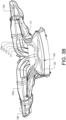
Fig. 3B is a cut view from below of the air intake device inFig. 3A , and -
Fig. 4 is a schematic view of a vehicle with the air intake device shown inFig. 3A installed. -
Fig. 1A is a cut view of anair intake device 1 for providing air to an air conditioning system or HVAC 2 (schematically indicated) of a vehicle. Theair intake device 1 comprises a collectingcomponent 3 with anopening 4 for receiving air, aduct 5 arranged for transporting air from the collectingcomponent 3 to theair conditioning system 2, and adrainage container 6. Theduct 5 is suitably closed, preferably along the entire extension from thecollecting component 3 to theair conditioning system 2. Thedrainage container 6 is also closed against the surrounding. - Further, the
duct 5 has afirst duct part 5a extending from thecollecting component 3 to aninlet 7 of thedrainage container 6, which allows air to flow from thecollecting component 3 and into thedrainage container 6, and a second duct part 5b extending from anoutlet 8 of thedrainage container 6 to theair conditioning system 2, which allows air to flow out from thedrainage container 6 and to theair conditioning system 2. - The
inlet 7 and theoutlet 8 are arranged such that anairflow direction 9 of theinlet 7 and anairflow direction 10 of theoutlet 8 form an angle α in the interval 90°≤α≤270° relative to each other, thereby redirecting the airflow in thedrainage container 6. Theinlet airflow direction 9 and theoutlet airflow direction 10 are the main directions of the airflow into and out from thedrainage container 6, respectively. - In the example embodiment illustrated in
Fig. 1A , the angle α is 180° between theairflow direction 9 of theinlet 7 and theairflow direction 10 of theoutlet 8. In other words; theinlet 7 and theoutlet 8 are arranged such that theairflow direction 10 of theoutlet 8 is substantially opposite to theairflow direction 9 of theinlet 7. - A cartesian coordinate system X, Y, Z, where all axes are orthogonal to each other, is introduced in
Fig. 1A for facilitating the explanation of theair intake device 1. - When the air intake device has its intended orientation, such as properly installed in a vehicle, the
outlet 8 is arranged above theinlet 7, i.e. at a higher position on the vertical axis Z. Further, thedrainage container 6 has awater drainage valve 11 arranged in thebottom 12 of thedrainage container 6, and suitably thedrainage valve 11 is arranged below theinlet 7, i.e. at a lower position on the vertical axis Z. - The
inlet 7 and theoutlet 8 can be arranged on one and thesame side 13 of thedrainage container 6, and suitably at substantially same position along the X-axis. InFig. 1B showing a cross section view taken along B-B inFig. 1A , it is shown that theinlet 7 and theoutlet 8 are arranged at one and thesame side 13 of thedrainage container 6 and at the same X-axis position. - The example embodiment of the
air intake device 1 illustrated inFig. 1A has apipe portion 14 arranged at theoutlet 8 inside thedrainage container 6, whichpipe portion 14 encloses theoutlet 8, i.e. thepipe portion 14 extends circumferentially around the outlet. Thepipe portion 14 projects from aninside surface 15 of thedrainage container 6 into thedrainage container 6 and constitutes a collar extending around the outlet opening. - The
pipe portion 14 is suitably an end portion of the second duct part 5b or an extension thereof, which end portion extends into thedrainage container 6 and ends inside thedrainage container 6. - Optionally, the
pipe portion 14 or collar arranged at theoutlet 8 is a separate pipe portion attached to theinside surface 15. Such a pipe portion may have substantially the same dimensions as theoutlet 8. For example, in case the outlet and the pipe portion both have circular cross sections, the inner diameter of the pipe portion can be equal to or somewhat greater than the diameter of the outlet opening. - In the same way as described with respect to the
outlet 8 hereinabove, theair intake device 1 can have a pipe portion (not shown inFig. 1A ) arranged at theinlet 7 inside thedrainage container 6, which pipe portion encloses theinlet 7, i.e. the pipe portion extends circumferentially around the inlet. The pipe portion can project from aninside surface 15 of thedrainage container 6 into thedrainage container 6 and constitute a collar extending around the inlet opening. - The pipe portion is suitably an end portion of the
first duct part 5a or an extension thereof, which end portion extends into thedrainage container 6 and ends inside thedrainage container 6. - Optionally, the pipe portion or collar arranged at the
inlet 7 is a separate pipe portion attached to theinside surface 15. Such a pipe portion may have substantially the same dimensions as theinlet 7. For example, in case the inlet and the pipe portion both have circular cross sections, the inner diameter of the pipe portion can be equal to or somewhat greater than the diameter of the inlet opening. -
Fig. 2 shows a variant of the air intake device 1' where theinlet 7 and the outlet 8' are arranged such that the angle α formed between theairflow direction 9 of theinlet 7 and the airflow direction 10' of the outlet 8' is 90° for redirecting the airflow in thedrainage container 6 correspondingly. -
Fig. 3A shows a further variant of theair intake device 101 where the device comprises two of saidduct 105 arranged for transporting air from the collectingcomponent 103 to the air conditioning system or HVAC 102 (schematically indicated) and two of saiddrainage container 106. Further, anair filter 125 is suitably arranged downstream thedrainage containers 106 and upstream theair conditioning system 102. - For each drainage container, the
first duct part 105a extends from the collectingcomponent 103 to theinlet 107 of thedrainage container 106, which allows air to flow from the collectingcomponent 103 and into thedrainage container 106, and thesecond duct part 105b extends from theoutlet 108 of thedrainage container 106 to theair conditioning system 102, which allows air to flow out from thedrainage container 106 and to theair conditioning system 102. - In the same way as explained with reference to the example embodiment illustrated in
Fig. 1A , also in this example embodiment illustrated inFig. 3A , the angle α is approximately 180° between theairflow direction 109 of theinlet 107 and theairflow direction 110 of theoutlet 108. In other words; theinlet 107 and theoutlet 108 are arranged such that theairflow direction 110 of theoutlet 108 is substantially opposite to theairflow direction 109 of theinlet 107. - As appears from the partly cut view in
Fig. 3A , thepipe portion 114 arranged at theoutlet 108 inside thedrainage container 106 encloses theoutlet 108, i.e. thepipe portion 114 extends circumferentially around the outlet. Thepipe portion 114 is the end portion of thesecond duct part 105b, which end portion extends into thedrainage container 106 and ends inside thedrainage container 106. Thepipe portion 114 projects from theinside surface 115 into thedrainage container 6 and constitutes a collar extending around the outlet opening. - As further appears from the partly cut view in
Fig. 3A , the pipe portion 114' arranged at theinlet 107 inside thedrainage container 106 encloses theinlet 107, i.e. the pipe portion 114' extends circumferentially around the inlet. The pipe portion 114' is the end portion of thefirst duct part 105a, which end portion extends into thedrainage container 106 and ends inside thedrainage container 106. The pipe portion 114' projects from theinside surface 115 into thedrainage container 6 and constitutes a collar extending around the inlet opening. -
Fig. 3B is a cut view from below of theair intake device 101 illustrated inFig. 3A .Fig. 3B shows the inside of eachfirst duct part 105a connecting thecollector component 103 and therespective drainage container 106. - The
first duct part 105a suitably has at least oneinternal guiding vane 116 arranged to counteract swirling of the air before entering thedrainage container 106. Preferably, said at least one guidingvane 116 extends in a longitudinal direction of thefirst duct part 105a and divides thefirst duct part 105a into a plurality oflongitudinal air channels 117. In the example embodiment illustrated inFigs. 3A and3B , eachfirst duct part 105a has two guidingvanes 116 providing threeair channels 117. The guidingvanes 116 can also be used for initially dividing the main airflow reaching thecollector component 103 into a first sub airflow directed to one of the drainage containers and second sub airflow directed to the other of the drainage containers. -
Fig. 4 shows avehicle 120 comprising anair intake device 101. For example, theair intake device 101 can be the same as illustrated inFig. 3A , where eachdrainage container 106 is arranged at a respective side of thevehicle 120 for drainage of water at a respectivefront wheel arch 121 of thevehicle 120. - When the
air intake device 101 is arranged in avehicle 120, the directions and axes used in the cartesian coordinate system, i.e. the X-axis, Y-axis and the Z-axis, are arranged relative to thevehicle 120 such that the X-axis is a horizontal axis in parallel with the longitudinal extension direction or normal driving direction of thevehicle 120, the Y-axis is a horizontal axis in parallel with the lateral extension of thevehicle 120, and the Z-axis is a vertical axis. - It is to be understood that the present invention is not limited to the embodiments described above and illustrated in the drawings; rather, the skilled person will recognize that many changes and modifications may be made within the scope of the appended claims.
Claims (15)
- An air intake device (1; 101) for providing air to an air conditioning system (2; 102) of a vehicle (120), the air intake device comprising a collecting component (3; 103) with an opening (4; 104) for receiving air, a duct (5; 105) arranged for transporting air from the collecting component to the air conditioning system, and a drainage container (6; 106), wherein the duct has a first duct part (5a; 105a) extending from the collecting component to an inlet (7; 107) of the drainage container, allowing air to flow from the collecting component and into the drainage container, and a second duct part (5; 105b) extending from an outlet (8; 108) of the drainage container to the air conditioning system, allowing air to flow out from the drainage container and to the air conditioning system, wherein the inlet (7; 107) and the outlet (8; 108) are arranged such that an airflow direction (9; 109) of the inlet and an airflow direction (10; 110) of the outlet form an angle α in the interval 90°≤α≤270° relative to each other thereby redirecting an airflow in the drainage container.
- An air intake device according to claim 1, characterized in that the angle α is in the interval 140°≤α≤220°.
- An air intake device according to claim 1, characterized in that the angle α is in the interval 160°≤α≤200°.
- An air intake device according to claim 1, characterized in that the angle α is in the interval 170°<α<190°.
- An air intake device according to claim 1, characterized in that the airflow direction (10; 110) of the outlet is substantially opposite to the airflow direction (9; 109) of the inlet.
- An air intake device according to any preceding claim, characterized in that the outlet (8; 108) is arranged above the inlet (7; 107).
- An air intake device according to any preceding claim, characterized in that the air intake device (1; 101) has a pipe portion (14; 114) arranged at the outlet (8; 108) inside the drainage container (6; 106), which pipe portion (14; 114) encloses the outlet.
- An air intake device according to claim 7, characterized in that the pipe portion (14; 114) is an end portion of the second duct part (5b; 105b), which end portion extends into the drainage container (6; 106) and ends inside the drainage container.
- An air intake device according to any preceding claim, characterized in that the inlet (7; 107) and the outlet (8; 108) are arranged on one and the same side (13) of the drainage container (6; 106).
- An air intake device according to any preceding claim, characterized in that the drainage container (6; 106) has a water drainage valve (11; 111) arranged in the bottom of the drainage container.
- An air intake device according to any preceding claim, characterized in that the first duct part (105a) has at least one internal guiding vane (116) arranged to counteract swirling of the air before entering the drainage container (106).
- An air intake device according to claim 11, characterized in that said at least one guiding vane (116) extends in a longitudinal direction of the first duct part (105a) and divides the first duct part into a plurality of longitudinal air channels (117).
- An air intake device according to any preceding claim, characterized in that the air intake device (101) comprises two of said duct (105) arranged for transporting air from the collecting component (103) to the air conditioning system (102), and two of said drainage container (106).
- A vehicle (120) comprising an air intake device (1; 101) according to any of claims 1-13.
- A vehicle according to claim 14, the air intake device (101) comprising two of said duct (105) arranged for transporting air from the collecting component (103) to the air conditioning system (102), and two of said drainage container (106), wherein each drainage container is arranged at a respective side of the vehicle (120) for drainage of water at a respective front wheel arch (121) of the vehicle.
Priority Applications (4)
| Application Number | Priority Date | Filing Date | Title |
|---|---|---|---|
| EP22198356.2A EP4344915B1 (en) | 2022-09-28 | 2022-09-28 | An air intake device |
| CN202380068568.4A CN119947908A (en) | 2022-09-28 | 2023-09-22 | Air intake device |
| PCT/CN2023/120596 WO2024067384A1 (en) | 2022-09-28 | 2023-09-22 | An air intake device |
| US19/078,075 US20250242655A1 (en) | 2022-09-28 | 2025-03-12 | Air intake device |
Applications Claiming Priority (1)
| Application Number | Priority Date | Filing Date | Title |
|---|---|---|---|
| EP22198356.2A EP4344915B1 (en) | 2022-09-28 | 2022-09-28 | An air intake device |
Publications (2)
| Publication Number | Publication Date |
|---|---|
| EP4344915A1 true EP4344915A1 (en) | 2024-04-03 |
| EP4344915B1 EP4344915B1 (en) | 2026-04-01 |
Family
ID=83505756
Family Applications (1)
| Application Number | Title | Priority Date | Filing Date |
|---|---|---|---|
| EP22198356.2A Active EP4344915B1 (en) | 2022-09-28 | 2022-09-28 | An air intake device |
Country Status (4)
| Country | Link |
|---|---|
| US (1) | US20250242655A1 (en) |
| EP (1) | EP4344915B1 (en) |
| CN (1) | CN119947908A (en) |
| WO (1) | WO2024067384A1 (en) |
Citations (5)
| Publication number | Priority date | Publication date | Assignee | Title |
|---|---|---|---|---|
| DE4303663C1 (en) * | 1993-02-09 | 1994-03-31 | Daimler Benz Ag | Water separation fresh air intake for vehicle - has water collection chambers and air path with flow reversal. |
| FR2938213A1 (en) * | 2008-11-07 | 2010-05-14 | Peugeot Citroen Automobiles Sa | Motor vehicle front part, has mechanical units implanted on two vertical and transversal walls of parallelepiped case for reducing amplitude of undulations of rain water accumulated at bottom surface of cowl |
| EP2236332A2 (en) * | 2008-12-22 | 2010-10-06 | Weidmann Plastics Technology AG | Water chamber for a motor vehicle and motor vehicle with such a water chamber |
| CN107042742A (en) * | 2015-12-09 | 2017-08-15 | 福特全球技术公司 | For the apparatus and method for the ventilation unit that vent air is supplied to vehicle interior, and motor vehicles |
| DE102020131659A1 (en) * | 2020-11-30 | 2022-06-02 | Dr. Ing. H.C. F. Porsche Aktiengesellschaft | Air supply device for an air conditioning system in a motor vehicle |
Family Cites Families (1)
| Publication number | Priority date | Publication date | Assignee | Title |
|---|---|---|---|---|
| DE102004051198B3 (en) * | 2004-10-21 | 2006-06-22 | Daimlerchrysler Ag | Fresh air supply device for motor vehicle has droplet removing chamber forming air channel running along flat horizontal curve |
-
2022
- 2022-09-28 EP EP22198356.2A patent/EP4344915B1/en active Active
-
2023
- 2023-09-22 WO PCT/CN2023/120596 patent/WO2024067384A1/en not_active Ceased
- 2023-09-22 CN CN202380068568.4A patent/CN119947908A/en active Pending
-
2025
- 2025-03-12 US US19/078,075 patent/US20250242655A1/en active Pending
Patent Citations (5)
| Publication number | Priority date | Publication date | Assignee | Title |
|---|---|---|---|---|
| DE4303663C1 (en) * | 1993-02-09 | 1994-03-31 | Daimler Benz Ag | Water separation fresh air intake for vehicle - has water collection chambers and air path with flow reversal. |
| FR2938213A1 (en) * | 2008-11-07 | 2010-05-14 | Peugeot Citroen Automobiles Sa | Motor vehicle front part, has mechanical units implanted on two vertical and transversal walls of parallelepiped case for reducing amplitude of undulations of rain water accumulated at bottom surface of cowl |
| EP2236332A2 (en) * | 2008-12-22 | 2010-10-06 | Weidmann Plastics Technology AG | Water chamber for a motor vehicle and motor vehicle with such a water chamber |
| CN107042742A (en) * | 2015-12-09 | 2017-08-15 | 福特全球技术公司 | For the apparatus and method for the ventilation unit that vent air is supplied to vehicle interior, and motor vehicles |
| DE102020131659A1 (en) * | 2020-11-30 | 2022-06-02 | Dr. Ing. H.C. F. Porsche Aktiengesellschaft | Air supply device for an air conditioning system in a motor vehicle |
Also Published As
| Publication number | Publication date |
|---|---|
| CN119947908A (en) | 2025-05-06 |
| EP4344915B1 (en) | 2026-04-01 |
| US20250242655A1 (en) | 2025-07-31 |
| WO2024067384A1 (en) | 2024-04-04 |
Similar Documents
| Publication | Publication Date | Title |
|---|---|---|
| CN102602264B (en) | Steam line and include the vehicle of this steam line | |
| US10100715B2 (en) | Inter cooler | |
| JP7094091B2 (en) | Gas-liquid separator | |
| US12558943B2 (en) | Air conditioning system | |
| EP3048375B1 (en) | Air conditioner | |
| US20110138758A1 (en) | Conduit piece for the absorption of foreign bodies | |
| US5800582A (en) | Compact water collector | |
| EP4344915B1 (en) | An air intake device | |
| US8813908B1 (en) | HVAC blower with noise suppression features | |
| EP4268926B1 (en) | Gas-liquid separator | |
| EP3276139B1 (en) | Pipe connection structure | |
| WO2009087683A2 (en) | Fresh air duct for vehicle air conditioning system | |
| US20140024303A1 (en) | Air conditioning system for motor vehicle | |
| CN109869218A (en) | Compact waste gas purification and recycling device | |
| US12611623B2 (en) | Gas-liquid separator | |
| EP3587153B1 (en) | Blower for vehicle air conditioner | |
| US20090180870A1 (en) | Blower Motor Flange Diverter | |
| CN109707542B (en) | ventilation duct | |
| US12370869B2 (en) | HVAC air inlet assemblies and methods | |
| US20140020347A1 (en) | Particle separator for an air conduit, air distribution system, use of a particle separator and aircraft | |
| CN217099603U (en) | Foot blowing air pipe | |
| EP3533990B1 (en) | Tubular condensate separator | |
| JP2025000552A (en) | Airflow mix manifold | |
| CN122070223A (en) | Heating, ventilation and/or air conditioning housing and device, in particular for a motor vehicle |
Legal Events
| Date | Code | Title | Description |
|---|---|---|---|
| PUAI | Public reference made under article 153(3) epc to a published international application that has entered the european phase |
Free format text: ORIGINAL CODE: 0009012 |
|
| STAA | Information on the status of an ep patent application or granted ep patent |
Free format text: STATUS: REQUEST FOR EXAMINATION WAS MADE |
|
| 17P | Request for examination filed |
Effective date: 20220928 |
|
| AK | Designated contracting states |
Kind code of ref document: A1 Designated state(s): AL AT BE BG CH CY CZ DE DK EE ES FI FR GB GR HR HU IE IS IT LI LT LU LV MC MK MT NL NO PL PT RO RS SE SI SK SM TR |
|
| GRAP | Despatch of communication of intention to grant a patent |
Free format text: ORIGINAL CODE: EPIDOSNIGR1 |
|
| STAA | Information on the status of an ep patent application or granted ep patent |
Free format text: STATUS: GRANT OF PATENT IS INTENDED |
|
| INTG | Intention to grant announced |
Effective date: 20251030 |
|
| RIN1 | Information on inventor provided before grant (corrected) |
Inventor name: ANDREASSON, PATRIK Inventor name: KARLSSON, ANDERS Inventor name: FRIBERG, HENRIK Inventor name: LEVIN, JOHAN |
|
| GRAS | Grant fee paid |
Free format text: ORIGINAL CODE: EPIDOSNIGR3 |
|
| GRAA | (expected) grant |
Free format text: ORIGINAL CODE: 0009210 |
|
| STAA | Information on the status of an ep patent application or granted ep patent |
Free format text: STATUS: THE PATENT HAS BEEN GRANTED |
|
| AK | Designated contracting states |
Kind code of ref document: B1 Designated state(s): AL AT BE BG CH CY CZ DE DK EE ES FI FR GB GR HR HU IE IS IT LI LT LU LV MC MK MT NL NO PL PT RO RS SE SI SK SM TR |
|
| REG | Reference to a national code |
Ref country code: CH Ref legal event code: F10 Free format text: ST27 STATUS EVENT CODE: U-0-0-F10-F00 (AS PROVIDED BY THE NATIONAL OFFICE) Effective date: 20260401 Ref country code: GB Ref legal event code: FG4D |
|
| REG | Reference to a national code |
Ref country code: IE Ref legal event code: FG4D |
|
| REG | Reference to a national code |
Ref country code: DE Ref legal event code: R096 Ref document number: 602022033357 Country of ref document: DE |