EP4344879A1 - Printing apparatus - Google Patents
Printing apparatus Download PDFInfo
- Publication number
- EP4344879A1 EP4344879A1 EP23197382.7A EP23197382A EP4344879A1 EP 4344879 A1 EP4344879 A1 EP 4344879A1 EP 23197382 A EP23197382 A EP 23197382A EP 4344879 A1 EP4344879 A1 EP 4344879A1
- Authority
- EP
- European Patent Office
- Prior art keywords
- waste ink
- ink tank
- shielding
- printing apparatus
- insertion port
- Prior art date
- Legal status (The legal status is an assumption and is not a legal conclusion. Google has not performed a legal analysis and makes no representation as to the accuracy of the status listed.)
- Pending
Links
Images







Classifications
-
- B—PERFORMING OPERATIONS; TRANSPORTING
- B41—PRINTING; LINING MACHINES; TYPEWRITERS; STAMPS
- B41J—TYPEWRITERS; SELECTIVE PRINTING MECHANISMS, i.e. MECHANISMS PRINTING OTHERWISE THAN FROM A FORME; CORRECTION OF TYPOGRAPHICAL ERRORS
- B41J2/00—Typewriters or selective printing mechanisms characterised by the printing or marking process for which they are designed
- B41J2/005—Typewriters or selective printing mechanisms characterised by the printing or marking process for which they are designed characterised by bringing liquid or particles selectively into contact with a printing material
- B41J2/01—Ink jet
- B41J2/17—Ink jet characterised by ink handling
- B41J2/1721—Collecting waste ink; Collectors therefor
-
- B—PERFORMING OPERATIONS; TRANSPORTING
- B41—PRINTING; LINING MACHINES; TYPEWRITERS; STAMPS
- B41J—TYPEWRITERS; SELECTIVE PRINTING MECHANISMS, i.e. MECHANISMS PRINTING OTHERWISE THAN FROM A FORME; CORRECTION OF TYPOGRAPHICAL ERRORS
- B41J2/00—Typewriters or selective printing mechanisms characterised by the printing or marking process for which they are designed
- B41J2/005—Typewriters or selective printing mechanisms characterised by the printing or marking process for which they are designed characterised by bringing liquid or particles selectively into contact with a printing material
- B41J2/01—Ink jet
- B41J2/17—Ink jet characterised by ink handling
- B41J2/175—Ink supply systems ; Circuit parts therefor
- B41J2/17503—Ink cartridges
-
- B—PERFORMING OPERATIONS; TRANSPORTING
- B41—PRINTING; LINING MACHINES; TYPEWRITERS; STAMPS
- B41J—TYPEWRITERS; SELECTIVE PRINTING MECHANISMS, i.e. MECHANISMS PRINTING OTHERWISE THAN FROM A FORME; CORRECTION OF TYPOGRAPHICAL ERRORS
- B41J2/00—Typewriters or selective printing mechanisms characterised by the printing or marking process for which they are designed
- B41J2/005—Typewriters or selective printing mechanisms characterised by the printing or marking process for which they are designed characterised by bringing liquid or particles selectively into contact with a printing material
- B41J2/01—Ink jet
- B41J2/17—Ink jet characterised by ink handling
- B41J2/175—Ink supply systems ; Circuit parts therefor
- B41J2/17503—Ink cartridges
- B41J2/1752—Mounting within the printer
-
- B—PERFORMING OPERATIONS; TRANSPORTING
- B41—PRINTING; LINING MACHINES; TYPEWRITERS; STAMPS
- B41J—TYPEWRITERS; SELECTIVE PRINTING MECHANISMS, i.e. MECHANISMS PRINTING OTHERWISE THAN FROM A FORME; CORRECTION OF TYPOGRAPHICAL ERRORS
- B41J2/00—Typewriters or selective printing mechanisms characterised by the printing or marking process for which they are designed
- B41J2/005—Typewriters or selective printing mechanisms characterised by the printing or marking process for which they are designed characterised by bringing liquid or particles selectively into contact with a printing material
- B41J2/01—Ink jet
- B41J2/17—Ink jet characterised by ink handling
- B41J2/175—Ink supply systems ; Circuit parts therefor
- B41J2/17503—Ink cartridges
- B41J2/1752—Mounting within the printer
- B41J2/17523—Ink connection
-
- B—PERFORMING OPERATIONS; TRANSPORTING
- B41—PRINTING; LINING MACHINES; TYPEWRITERS; STAMPS
- B41J—TYPEWRITERS; SELECTIVE PRINTING MECHANISMS, i.e. MECHANISMS PRINTING OTHERWISE THAN FROM A FORME; CORRECTION OF TYPOGRAPHICAL ERRORS
- B41J2/00—Typewriters or selective printing mechanisms characterised by the printing or marking process for which they are designed
- B41J2/005—Typewriters or selective printing mechanisms characterised by the printing or marking process for which they are designed characterised by bringing liquid or particles selectively into contact with a printing material
- B41J2/01—Ink jet
- B41J2/17—Ink jet characterised by ink handling
- B41J2/175—Ink supply systems ; Circuit parts therefor
- B41J2/17503—Ink cartridges
- B41J2/17526—Electrical contacts to the cartridge
-
- B—PERFORMING OPERATIONS; TRANSPORTING
- B41—PRINTING; LINING MACHINES; TYPEWRITERS; STAMPS
- B41J—TYPEWRITERS; SELECTIVE PRINTING MECHANISMS, i.e. MECHANISMS PRINTING OTHERWISE THAN FROM A FORME; CORRECTION OF TYPOGRAPHICAL ERRORS
- B41J2/00—Typewriters or selective printing mechanisms characterised by the printing or marking process for which they are designed
- B41J2/005—Typewriters or selective printing mechanisms characterised by the printing or marking process for which they are designed characterised by bringing liquid or particles selectively into contact with a printing material
- B41J2/01—Ink jet
- B41J2/17—Ink jet characterised by ink handling
- B41J2/175—Ink supply systems ; Circuit parts therefor
- B41J2/17503—Ink cartridges
- B41J2/17536—Protection of cartridges or parts thereof, e.g. tape
-
- B—PERFORMING OPERATIONS; TRANSPORTING
- B41—PRINTING; LINING MACHINES; TYPEWRITERS; STAMPS
- B41J—TYPEWRITERS; SELECTIVE PRINTING MECHANISMS, i.e. MECHANISMS PRINTING OTHERWISE THAN FROM A FORME; CORRECTION OF TYPOGRAPHICAL ERRORS
- B41J2/00—Typewriters or selective printing mechanisms characterised by the printing or marking process for which they are designed
- B41J2/005—Typewriters or selective printing mechanisms characterised by the printing or marking process for which they are designed characterised by bringing liquid or particles selectively into contact with a printing material
- B41J2/01—Ink jet
- B41J2/17—Ink jet characterised by ink handling
- B41J2/175—Ink supply systems ; Circuit parts therefor
- B41J2/17503—Ink cartridges
- B41J2/17543—Cartridge presence detection or type identification
-
- B—PERFORMING OPERATIONS; TRANSPORTING
- B41—PRINTING; LINING MACHINES; TYPEWRITERS; STAMPS
- B41J—TYPEWRITERS; SELECTIVE PRINTING MECHANISMS, i.e. MECHANISMS PRINTING OTHERWISE THAN FROM A FORME; CORRECTION OF TYPOGRAPHICAL ERRORS
- B41J2/00—Typewriters or selective printing mechanisms characterised by the printing or marking process for which they are designed
- B41J2/005—Typewriters or selective printing mechanisms characterised by the printing or marking process for which they are designed characterised by bringing liquid or particles selectively into contact with a printing material
- B41J2/01—Ink jet
- B41J2/17—Ink jet characterised by ink handling
- B41J2/175—Ink supply systems ; Circuit parts therefor
- B41J2/17503—Ink cartridges
- B41J2/17553—Outer structure
-
- B—PERFORMING OPERATIONS; TRANSPORTING
- B41—PRINTING; LINING MACHINES; TYPEWRITERS; STAMPS
- B41J—TYPEWRITERS; SELECTIVE PRINTING MECHANISMS, i.e. MECHANISMS PRINTING OTHERWISE THAN FROM A FORME; CORRECTION OF TYPOGRAPHICAL ERRORS
- B41J2/00—Typewriters or selective printing mechanisms characterised by the printing or marking process for which they are designed
- B41J2/005—Typewriters or selective printing mechanisms characterised by the printing or marking process for which they are designed characterised by bringing liquid or particles selectively into contact with a printing material
- B41J2/01—Ink jet
- B41J2/17—Ink jet characterised by ink handling
- B41J2/18—Ink recirculation systems
- B41J2/185—Ink-collectors; Ink-catchers
-
- B—PERFORMING OPERATIONS; TRANSPORTING
- B41—PRINTING; LINING MACHINES; TYPEWRITERS; STAMPS
- B41J—TYPEWRITERS; SELECTIVE PRINTING MECHANISMS, i.e. MECHANISMS PRINTING OTHERWISE THAN FROM A FORME; CORRECTION OF TYPOGRAPHICAL ERRORS
- B41J29/00—Details of, or accessories for, typewriters or selective printing mechanisms not otherwise provided for
- B41J29/12—Guards, shields or dust excluders
- B41J29/13—Cases or covers
-
- B—PERFORMING OPERATIONS; TRANSPORTING
- B41—PRINTING; LINING MACHINES; TYPEWRITERS; STAMPS
- B41J—TYPEWRITERS; SELECTIVE PRINTING MECHANISMS, i.e. MECHANISMS PRINTING OTHERWISE THAN FROM A FORME; CORRECTION OF TYPOGRAPHICAL ERRORS
- B41J2/00—Typewriters or selective printing mechanisms characterised by the printing or marking process for which they are designed
- B41J2/005—Typewriters or selective printing mechanisms characterised by the printing or marking process for which they are designed characterised by bringing liquid or particles selectively into contact with a printing material
- B41J2/01—Ink jet
- B41J2/17—Ink jet characterised by ink handling
- B41J2/18—Ink recirculation systems
-
- B—PERFORMING OPERATIONS; TRANSPORTING
- B41—PRINTING; LINING MACHINES; TYPEWRITERS; STAMPS
- B41J—TYPEWRITERS; SELECTIVE PRINTING MECHANISMS, i.e. MECHANISMS PRINTING OTHERWISE THAN FROM A FORME; CORRECTION OF TYPOGRAPHICAL ERRORS
- B41J2/00—Typewriters or selective printing mechanisms characterised by the printing or marking process for which they are designed
- B41J2/005—Typewriters or selective printing mechanisms characterised by the printing or marking process for which they are designed characterised by bringing liquid or particles selectively into contact with a printing material
- B41J2/01—Ink jet
- B41J2/17—Ink jet characterised by ink handling
- B41J2/18—Ink recirculation systems
- B41J2/185—Ink-collectors; Ink-catchers
- B41J2002/1856—Ink-collectors; Ink-catchers waste ink containers
Definitions
- the present invention relates to a printing apparatus with a waste ink tank that reserves waste ink and is provided replaceably in the apparatus.
- a printing apparatus that ejects ink to perform printing includes a recovery portion for maintaining and recovering ink ejection performance satisfactorily.
- a waste ink tank for storing waste ink received in the recovery portion is provided replaceably.
- Japanese Patent Laid-Open No. 2021-109415 discloses a technique in which a storage portion that stores a waste ink tank includes a shielding member that shields a discharge portion that discharges waste ink to the waste ink tank in order to suppress adhesion of waste ink to hands, clothes, and the like at the time of replacing of the waste ink tank.
- the present invention provides a waste ink tank that can be replaced properly.
- the present invention in its first aspect provides a printing apparatus as specified in claims 1 to 15.
- a printing apparatus with a waste ink tank according to the present embodiment may be an apparatus having only the function of printing an image on a print medium, or a multifunction device having the function of reading an image.
- a multifunction device that has the function of reading an image and can print an image on a print medium will be described as an example of the printing apparatus with the waste ink tank according to the present embodiment.
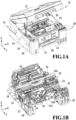
- FIGs. 1A and 1B are configuration diagrams of the printing apparatus according to the present embodiment.
- FIG. 1A is an external view of the printing apparatus with a reader opened and
- FIG. 1B is a schematic configuration diagram of a main portion of a printing portion.
- FIG. 2 is a schematic configuration diagram of a recovery portion and the waste ink tank.
- a direction from a left side to a right side of the apparatus is an X direction
- a direction from a back side to a front side is a Y direction
- a direction from a lower side to an upper side is a Z direction.
- the X direction, Y direction, and Z direction are directions from one side to the other side and will be indicated with "+ (plus)” as appropriate
- the X direction, Y direction, and Z direction from the other side to one side will be indicated with "- (minus).”
- a printing apparatus 10 includes a reader 12 capable of reading an image on a document, a printing portion 14 capable of printing an image on a print medium based on image data, and an operation portion 16 that receives an input of an instruction from a user and can display various kinds of information.
- the reader 12 is provided above the printing portion 14 so as to be openable and closable.
- various publicly-known techniques can be used for the configurations of the reader 12 and the operation portion 16, the detailed descriptions thereof will be omitted in the following description.
- the printing portion 14 includes a conveyance roller 18 that conveys a fed print medium, a platen 20 that supports the print medium conveyed by the conveyance roller 18, and a print head 22 that ejects ink onto the print medium supported by the platen 20 to perform printing.
- the printing portion 14 also includes a discharge roller 23 that discharges the print medium printed by the print head 22 to a tray (not shown).
- the printing portion 14 includes a pinch roller 24 that is pressed against and is associated with the conveyance roller 18, and a print medium is pinched between the conveyance roller 18 and the pinch roller 24 and can be conveyed in the ⁇ Y directions.
- the print head 22 is detachably mounted on a carriage 26 provided movably in the ⁇ X directions. Accordingly, in the printing portion 14, the print head 22 is configured to be movable in the ⁇ X directions via the carriage 26.
- the platen 20 extends in the X direction a length corresponding to the length in a width direction of a printable print medium.
- the printing portion 14 After a print medium is conveyed to a print start position by the conveyance roller 18, the printing portion 14 performs a printing operation in which ink is ejected onto the print medium while the print head 22 is moved in the X direction (or the -X direction) to perform printing. Next, a conveyance operation in which the conveyance roller 18 conveys the print medium by a predetermined amount in the Y direction is performed, an unprinted area is located in a position opposite to the print head 22, and the printing operation is performed again. Alternately and repeatedly executing the printing operation and the conveyance operation in this way, the print medium is printed in the printing portion 14.
- the printing portion 14 includes an ink tank 28 that stores ink to be supplied to the print head 22 on the other side in the Y direction.
- the ink tank 28 is connected to the print head 22 through a tube 30, and ink stored in the ink tank 28 is supplied to the print head 22 through the tube 30.
- the printing portion 14 also includes a recovery portion 32 that executes a recovery operation for maintaining and recovering the ink ejection performance of the print head 22 satisfactorily.
- the standby position is a position where the print head 22 is on standby while printing is not performed and is, for example, a position near the end on the other side in the X direction in an area where the print head 22 moves including the carriage 26 (hereinafter simply referred to as "the movement area where the print head 22 moves” or “the movement area where a printing unit U moves (to be described later)").
- the printing portion 14 further includes a waste ink tank 34 into which waste ink received at the recovery portion 32 is discharged.
- the waste ink tank 34 is stored in a storage portion 38 provided adjacent to the movement area where the print head 22 moves in a print medium conveyance direction, more specifically, adjacent to the other side in the Y direction of the movement area.
- the recovery portion 32 includes a cap 202 that caps and protects an ejection port surface where an ink ejection port through which ink is ejected is formed in the print head 22, a wiper 204 for wiping off a deposit deposited on the ejection port surface, and a suction pump 206 for reducing pressure in the cap 202 (see FIG. 2 ).
- the cap 202 since black ink and color ink are ejected, the cap 202 includes a cap corresponding to an ejection port for ejecting black ink and a cap corresponding to an ejection port for ejecting color ink.
- the suction pump 206 is connected to a discharging tube 208.
- the discharging tube 208 is connected at one end to the suction pump 206 and at the other end to the waste ink tank 34 via a connection portion 210. That is, the recovery portion 32 is connected to the waste ink tank 34 via the discharging tube 208.
- waste ink received at the recovery portion 32 by, for example, executing various recovery operations is discharged to the waste ink tank 34 through the discharging tube 208.
- the connection portion 210 is provided with a needle portion 950 (see FIG. 9 ) and this needle portion 950 is inserted into an insertion port 408 (to be described later) of the waste ink tank 34, so that the discharging tube 208 is connected to the waste ink tank 34.
- the upper surface of the printing portion 14 is formed by a cover member 36 (see FIG. 1A ).
- the cover member 36 in a case where the reader 12 is opened, the cover member 36 is exposed to the outside.
- the cover member 36 In the cover member 36, there is formed an opening 40 through which a portion of the movement area where the print head 22 moves and the storage portion 38 that stores the waste ink tank 34 are exposed.
- the size of a portion where a portion of the movement area where the print head 22 moves is exposed is large enough for a user to put the user's hand into the movement area where the print head 22 moves or the like to remove a print medium, for example, in a case where paper-jamming (paper jam) occurs.
- a portion where the storage portion 38 is exposed is large enough to insert the waste ink tank 34 into the storage portion 38 in the -Z direction (gravitational direction).
- the storage portion 38 is located on the other side in the Y direction of the movement area where the print head 22 moves and on one side in the X direction of the movement area.
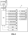
- FIG. 3 is a block diagram showing the configuration of the control system for the printing apparatus 10. Incidentally, FIG. 3 shows a main configuration with a focus on the printing portion 14 of the printing apparatus 10.
- the printing apparatus 10 includes an MPU 302 that controls all operations in the printing apparatus 10, such as the operation of each constituent and data processing, and a ROM 304 that stores various programs and various kinds of data executed by the MPU 302.
- the printing apparatus 10 also includes a RAM 306 that temporarily stores processing data executed by the MPU 302 and data received from a host computer 300 (to be described later).
- the MPU 302 is connected to a print head driver 308 to control driving of the print head 22 via the print head driver 308.
- the MPU 302 is also connected to a carriage motor driver 310 to control, via the carriage motor driver 310, driving of a carriage motor 312 that moves the carriage 26.
- the MPU 302 is connected to a conveyance motor driver 314 to control, via the conveyance motor driver 314, driving of a conveyance motor 316 that drives the conveyance roller 18 and the discharge roller 23.
- the MPU 302 is connected to a suction motor driver 318 to control a suction motor 320 that drives the suction pump 206 via the suction motor driver 318.
- the MPU 302 is connected to an interface (I/F) portion 322 and is connected to the host computer 300 via the I/F portion 322.
- the host computer 300 is provided with a driver 324 for collecting print information such as a print image and print quality and communicating with the printing apparatus 10 in a case where instructions to start printing are given by a user.
- the MPU 302 is also connected to a display portion 328 to control display on the operation portion 16 via the display portion 328. Further, the MPU 302 is connected to a detection portion 330 capable of detecting the amount of waste ink discharged to the waste ink tank 34. Based on a result of detection by the detection portion 330, the MPU 302 makes a notification to, for example, prompt for replacement of the waste ink tank 34 via the display portion 328.
- FIG. 4 is a perspective configuration diagram of the waste ink tank 34.
- the X direction, Y direction, and Z direction in the figures indicate directions in the case of storing the waste ink tank 34 in the storage portion 38.
- the waste ink tank 34 is replaced with a new waste ink tank 34 by an operator based on, for example, a notification displayed on the operation portion 16 to prompt for replacement of the waste ink tank 34.
- the waste ink tank 34 includes a substantially box-shaped container portion 402 (see FIG. 7 ) with a top opened and a lid portion 404 detachably fixed to the container portion 402 so as to cover the top opening of the container portion 402.
- the waste ink tank 34 also includes an absorbent 406 (see FIG. 7 ) that is contained in the container portion 402 and capable of absorbing waste ink.
- the container portion 402 is provided with the insertion port 408 opened so that the needle portion 950 (see FIG. 9 ) provided in the connection portion 210 (see FIG. 2 ) can be inserted and pulled out on a side surface 402a located on the other side in the Y direction in a case where the waste ink tank 34 is stored in the storage portion 38.
- the absorbent 406 contained in the container portion 402 is exposed from the opening of the insertion port 408.
- two insertion ports 408 are provided along the X direction. The needle portion 950 for discharging black waste ink is inserted into one insertion port 408, and the needle portion 950 for discharging color waste ink is inserted into the other insertion port 408.
- the waste ink tank 34 is inserted in the -Z direction from a position corresponding to the storage portion 38 of the opening 40. After that, the waste ink tank 34 is moved in the Y direction, and the needle portion 950 is inserted into the insertion port 408. That is, in the present embodiment, in a case where the waste ink tank 34 is stored in the storage portion 38, the needle portion 950 of the connection portion 210 is inserted into the insertion port 408. Waste ink is then discharged from the needle portion 950 into the container portion 402 through the discharging tube 208, and the discharged waste ink is absorbed into the absorbent 406. As described above, in the present embodiment, the needle portion 950 functions as a discharge member that discharges waste ink to the waste ink tank 34.
- connection terminal 412 that can be electrically connected to a connection terminal (not shown) provided in the storage portion 38 in a case where the waste ink tank 34 is stored in the storage portion 38.
- the connection terminal 412 is provided closer to one side in the Z direction than to the insertion port 408 and in a position different from that of the insertion port 408 in the X direction.
- the MPU 302 detects that the waste ink tank 34 is stored in the storage portion 38 by detecting that the connection terminal in the storage portion 38 is connected to the connection terminal 412 based on a result of detection by the detection portion 330. On the other hand, the MPU 302 detects that the waste ink tank 34 is removed from the storage portion 38 by detecting that the connection between the connection terminal in the storage portion 38 and the connection terminal 412 is released based on a result of detection by the detection portion 330. In the case of detecting that a waste ink tank 34 is newly stored in the storage portion 38, the MPU 302 stores the amount of waste ink stored in the newly attached waste ink tank 34.
- a shielding portion 414 capable of shielding and opening the insertion port 408 is provided on the side surface 402a of the container portion 402.
- the shielding portion 414 is configured to be movable between a shielding position and an open position.
- the shielding portion 414 shields the insertion port 408 from the outside by being located in the shielding position where the insertion port 408 is shielded.
- the absorbent 406 exposed from the insertion port 408 is shielded from the outside.
- the shielding portion 414 brings about a state where the insertion port 408 is exposed by being located in the open position where the insertion port 408 is opened. As a result, the absorbent 406 is exposed to the outside from the insertion port 408.
- the lid portion 404 is provided with an opening 410 for accelerating the evaporation of waste ink absorbed into the absorbent 406 inside the container portion 402.
- the lid portion 404 includes, for example, a plurality of hole sections 404a that can be fitted to a plurality of claw portions 402b provided in the container portion 402 (see FIG. 7 ).
- the hole sections 404a are fitted to the claw portions 402b, so that the lid portion 404 is fixed to the container portion 402 (see FIG. 4 ).
- a fixing mechanism for fixing the lid portion 404 to the container portion 402 is not limited to this.
- a gripping portion 416 that can be gripped by an operator is formed. The operator thus can grip the gripping portion 416 of the lid portion 404 fixed to the container portion 402 to move the waste ink tank 34.
- FIGs. 5A and 5B are diagrams showing an insertion portion provided in the absorbent 406 located within an opening area of the insertion port 408.
- FIG. 5A is a schematic configuration diagram of the insertion portion
- FIG. 5B is a diagram showing a state where the needle portion 950 is inserted into the insertion portion.
- the X direction, Y direction, and Z direction in the figures indicate directions in a case where the waste ink tank 34 is stored in the storage portion 38.
- FIG. 5B shows that the absorbent 406 is located only in a partial area in the container portion 402 in the vicinity of the insertion port 408 in order to facilitate understanding. That is, the absorbent 406 near the insertion port 408 is not limited to the form shown in FIG. 5B .
- the absorbent 406 is arranged inside the container portion 402 so as to be able to absorb waste ink discharged through the needle portion 950.
- the absorbent 406 is also formed with an insertion portion 502 through which the needle portion 950 can be inserted in a position corresponding to an opening area S1 of the insertion port 408, that is, in a position including a portion exposed from the insertion port 408.
- the insertion portion 502 has a size large enough to cover the entire opening area S1 and is formed of a plurality of linear cuts 504 that intersect with each other in a center position P1 of the opening area S1.
- a linear cut 508 along a direction in which a buckling portion 506 extends is formed in the center position of each buckling portion 506 that buckles in a case where the needle portion 950 is inserted.
- the cut 508 is formed in a position in contact with the opening area S1 (the position shown in FIG. 5A ) or is formed outside the opening area S1.
- the cut 508 is formed along the direction in which the buckling portion 506 extends in the center position of the buckling portion 506 connecting adjacent ends of the cut 504 (see FIG. 5A ).
- the length of the cut 508 is shorter than the length of the buckling portion 506 in which the cut 508 is formed (a length between the adjacent ends of the cut 504).
- the needle portion 950 in a case where the needle portion 950 is inserted from the insertion port 408, the needle portion 950 inserted from the vicinity of the center position P1 presses the insertion portion 502 in the -Y direction.
- a plurality of substantially triangular areas formed by the cuts 504 in the insertion portion 502 are deformed while contacting the needle portion 950 and bend in the -Y direction at the buckling portion 506 as shown in FIG. 5B .
- the cut 508 is formed in the center position of the buckling portion 506, the insertion portion 502 can be easily bent in the -Y direction, and a load generated at the time of insertion of the needle portion 950 is reduced.
- the insertion portion 502 does not have to be formed by the cuts 504 and 508 described above. That is, the insertion portion 502 may have any shape as long as there is formed a reduction portion capable of reducing a load to be generated on the needle portion 950 in a case where the needle portion 950 is inserted. In the above description, the cut 508 corresponds to the reduction portion.
- An insertion portion 502' in another form is, for example, formed of a substantially polygonal first opening 602 and substantially rectangular second openings 604 formed in positions corresponding to respective sides of the first opening 602, specifically, at predetermined distances from the respective sides (see FIGs. 6A and 6B).
- FIGs. 6A and 6B are diagrams showing the insertion portion 502'.
- FIG. 6A is a schematic configuration diagram of the insertion portion 502'
- FIG. 6B is a diagram showing the insertion portion 502' deformed due to the insertion of the needle portion 950.
- the X direction, Y direction, and Z direction in the figures indicate directions in a case where the waste ink tank 34 is stored in the storage portion 38.
- the first opening 602 is formed so that the center position thereof substantially coincides with the center position P1 of the opening area S1 and at least a portion of each side is located within the opening area S 1. As shown in FIG. 6A , the first opening 602 has, for example, a substantially square shape.
- the second opening 604 is provided on an extension of a direction in which the first opening 602 is deformed (hereinafter also referred to as "deformation direction") in a case where the needle portion 950 is inserted into the insertion portion 502'.
- An interval between the second opening 604 and the first opening 602 is an interval such that a gap portion gm between the second opening 604 and the first opening 602 can be deformed as a whole in the deformation direction in a case where the needle portion 950 is inserted into the insertion portion 502'.
- the length Ls of a short side of the substantially rectangular second opening 604 is preferably equal to or greater than the deformation amount ⁇ d of the gap portion gm in a case where the needle portion 950 is inserted into the insertion portion 502'. Further, the length Ll of a long side of the second opening 604 is, for example, substantially equal to the length of a corresponding side of the first opening 602. Incidentally, the shape of the second opening 604 is not limited to a substantially rectangular shape and may be any shape as long as the gap portion gm after deformation in a case where the needle portion 950 is inserted does not contact the inside of an opening in the second opening 604.
- the length of the second opening 604 in a direction in which a corresponding side of the first opening 602 is deformed in a case where the needle portion 950 is inserted is preferably equal to or greater than the deformation amount ⁇ d of the gap portion gm.
- Such a configuration in a case where the needle portion 950 is inserted from the insertion port 408, causes the needle portion 950 inserted from the vicinity of the center position P1 to press each side of the first opening 602 in a direction away from the center position P1 (the deformation direction described above). As a result, the gap portion gm is deformed in the direction away from the center position P1 while contacting the needle portion 950.
- the second opening 604 is provided on an extension of the direction in which the gap portion gm is deformed, and the length of the second opening 604 in the direction of deformation, that is, the length of the short side Ls is equal to or greater than the deformation amount ⁇ d of the gap portion.
- the deformation of the gap portion gm is absorbed by the second opening 604.
- the insertion portion 502' is easily deformed in a case where the needle portion 950 is inserted, and a load to be generated on the needle portion 950 at the time of insertion into the insertion port 408 is reduced. That is, in this case, the second opening 604 corresponds to the reduction portion that reduces a load to be generated on the needle portion 950 at the time of insertion.
- the shielding portion 414 is configured to be movable between the shielding position and the open position as described above. Specifically, in a case where the waste ink tank 34 is not stored in the storage portion 38, the shielding portion 414 is located in the shielding position. In a case where the waste ink tank 34 is stored in the storage portion 38, the shielding portion 414 is moved from the shielding position to the open position by a frame portion 900 (to be described later) provided in the storage portion 38. Further, in a case where the waste ink tank 34 is pulled out from the storage portion 38, the shielding portion 414 is separated from the frame portion 900 and moves from the open position to the shielding position.
- the configurations of the shielding portion 414 (including a moving mechanism) and the frame portion 900 and the operation of the shielding portion 414 will be described below. Configurations of the Shielding Portion and the Moving Mechanism of the Shielding Portion
- FIG. 7 is an exploded diagram of the waste ink tank 34.
- FIG. 8A is a perspective view of the waste ink tank 34 with the shielding portion 414 located in the shielding position and
- FIG. 8B is a perspective view of the waste ink tank 34 with the shielding portion 414 located in the open position.
- a holding portion 700 capable of holding the shielding portion 414 movably in the Z direction is formed on the side surface 402a of the container portion 402.
- the shielding portion 414 is arranged on the side surface 402a of the container portion 402 while being held by the holding portion 700.
- the holding portion 700 includes a rib 702 extending in the Z direction, a pair of convex portions 704 formed at an interval in the Z direction and protruding in the Y direction, and a spring receiving portion 706 that receives a spring 714 held between the holding portion 700 and the shielding portion 414.
- the shielding portion 414 includes a groove portion 708 that extends in the Z direction and can be fitted to the rib 702, an abutting portion 710 that is arranged between the pair of convex portions 704 and abuts against the pair of convex portions 704 at the time of the movement of the shielding portion 414 in the ⁇ Z directions, and a spring receiving portion 712 that receives the spring 714.
- the shielding portion 414 also includes a shielding member 716 that shields the insertion port 408 and an engagement portion 718 that engages the frame portion 900 in the case of storing the waste ink tank 34 in the storage portion 38.
- the spring 714 is held by the spring receiving portion 706 and the spring receiving portion 712.
- the spring 714 is arranged in the spring receiving portion 706 and the spring receiving portion 712 so as to bias the shielding portion 414 in the -Z direction (predetermined direction).
- the groove portion 708 is fitted to the rib 702 with the abutting portion 710 located between the pair of convex portions 704.
- the abutting portion 710 between the pair of convex portions 704 restricts movement of the shielding portion 414 in the ⁇ Z directions beyond a predetermined range including the shielding position and the open position.
- the shielding portion 414 is always biased in the -Z direction by the spring 714 and thus is located in the shielding position where the shielding member 716 shields the insertion port 408 (see FIG. 8A ) unless a force in the Z direction acts on the shielding portion 414.
- the abutting portion 710 contacts one convex portion 704a located on one side in the Z direction of the pair of convex portions 704, so that the movement of the shielding portion 414 in the -Z direction beyond the shielding position is restricted.
- the shielding portion 414 moves in the Z direction against the biasing force of the spring 714 in the -Z direction and is located in the open position where the shielding of the insertion port 408 by the shielding member 716 is released (see FIG. 8B ).
- the abutting portion 710 contacts the other convex portion 704b located on the other side in the Z direction of the pair of convex portions 704, so that the movement of the shielding portion 414 in the Z direction beyond the open position is restricted.
- the pair of convex portions 704 functions as a restriction member that restricts the movement of the shielding portion 414 in the -Z direction beyond the shielding position and also restricts the movement of the shielding portion 414 in the Z direction beyond the open position.
- the shielding portion 414 is provided in a portion where a step in the Y direction of the container portion 402 is formed, and movement in the X direction is restricted by the shape of the step, the pair of convex portions 704, the abutting portion 710, and the like.
- the engagement relationship between the shielding portion 414 and the holding portion 700 is not limited to the configuration described above, and various publicly-known techniques can be used.
- the frame portion has the function of guiding the waste ink tank 34 moved in the -Z direction, inserted into the storage portion 38, and located in the insertion position to a connection position where the waste ink tank 34 is connected to the needle portion 950 of the connection portion 210 and the function of moving the shielding portion 414 from the shielding position to the open position.
- FIG. 9 is a perspective configuration diagram of the frame portion 900 provided in the storage portion 38.
- the frame portion 900 includes a main body portion 902 to and from which the waste ink tank 34 can be attached and detached and a cover 904 provided on the other side in the Z direction of the main body portion 902.
- the shape of the cover 904 is shown in a simplified manner to facilitate understanding.
- the main body portion 902 includes a guide portion 905 that extends in the Y direction and can guide the movement of the waste ink tank 34 between the insertion position and the connection position and an erected portion 906 that is erected on the other side in the Y direction of the guide portion 905.
- the guide portion 905 includes a guide groove 908 into which a guide 720 (see FIG. 7 ) provided in the waste ink tank 34 is inserted and an engagement portion 910 that engages the shielding portion 414 between the insertion position and the connection position of the waste ink tank 34.
- the connection portion 210 is held so that the needle portion 950 is properly inserted into the insertion port 408 in a case where the waste ink tank 34 with the shielding portion 414 being in the open position moves to the connection position.
- the cover 904 is configured to cover the upper side of the connection portion 210 arranged in the main body portion 902. That is, the cover 904 covers the connection portion of the connection portion 210 at the erected portion 906 and the upper side of the exposed needle portion 950.
- the cover 904 may be formed integrally with the main body portion 902 or may be provided separately from the main body portion 902. In the case of being formed separately, the cover 904 may, for example, be fixedly connected to the cover member 36 or may be connected revolvably about an axis parallel to the X direction.
- FIGs. 1A and 1B an illustration of the cover 904 is omitted.
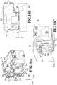
- FIGs. 10A to 10C are diagrams showing the waste ink tank 34 and the frame portion 900 in the insertion position.
- FIG. 10A is a perspective view seen from above
- FIG. 10B is a plan view
- FIG. 10C is a perspective view seen from below.
- FIGs. 11A to 11C are diagrams showing the waste ink tank 34 and the frame portion 900 in the connection position.
- FIG. 11A is a perspective view seen from above
- FIG. 11B is a plan view
- FIG. 11C is a perspective view seen from below.
- the cover 904 is omitted to facilitate understanding.
- FIGs. 10B and 10C and FIGs. 11B and 11C show the shape of the cover 904 in a simplified manner to facilitate understanding.
- the main body portion 902 is omitted to facilitate understanding.
- the positional relationship between the frame portion 900 and the waste ink tank 34 provided in the storage portion 38 is as shown in FIG. 10A .
- an operator first grips the gripping portion 416 with the operator's fingers, inserts the waste ink tank 34 into the storage portion 38 from the opening 40 in the -Z direction, and fits the guide 720 of the waste ink tank 34 into the guide groove 908 of the frame portion 900.
- the engagement portion 718 of the shielding portion 414 engages the engagement portion 910 of the frame portion 900.
- the operator then removes the operator's fingers from the gripping portion 416.
- the biasing force of the spring 714 is smaller than a force in the -Z direction generated under the weight of the waste ink tank 34.
- the shielding portion 414 maintains the position thereof in the Z direction, while the container portion 402 moves in the -Z direction. That is, the shielding portion 414 moves in the Z direction relatively with respect to the container portion 402. As a result, the shielding portion 414 is located in the open position and the insertion port 408 is opened.
- the present invention is not limited to this, and an operator may locate the shielding portion 414 in the open position by pressing the waste ink tank 34 in the -Z direction.
- the waste ink tank 34 is separated from the cover 904 in the Y direction (see FIG. 10B ).
- the needle portion 950 is separated from the insertion port 408 and is not inserted (see FIG. 10C ).
- the waste ink tank 34 After the waste ink tank 34 is located in the insertion position, an operator moves the waste ink tank 34 in the Y direction. As a result, the waste ink tank 34 is moved in the Y direction while being guided by the guide portion 905, and the needle portion 950 of the connection portion 210 fixed to the erected portion 906 is inserted into the insertion port 408 (see FIG. 11A ). The waste ink tank 34 is then moved and fixed to a position where the needle portion 950 is properly inserted into the insertion port 408, that is, the connection position where waste ink discharged from the needle portion 950 does not leak from the insertion port 408. A fixing mechanism for the waste ink tank 34 will be described later.
- connection terminal 412 of the waste ink tank 34 is connected to the connection terminal provided in the storage portion 38 in the connection position.
- the MPU 302 detects that a new waste ink tank 34 has been mounted and stores the amount of waste ink contained in the newly attached waste ink tank 34.
- the waste ink tank 34 is adjacent to the cover 904 in the Y direction (see FIG. 11B ).
- the waste ink tank 34 has a partial area on the other side in the Y direction where the insertion port 408 and the shielding portion 414 are located (see the broken line portion in FIG. 11B ), the upper side of the partial area being covered with the cover 904. That is, the cover 904 is provided so as to overlap a portion of the waste ink tank 34 in the connection position in the Y direction.
- the shape of the side 904a of the cover 904 on one side in the Y direction adjacent to the waste ink tank 34 corresponds to the shape of the adjacent waste ink tank 34 in the connection position.
- the upper surface of the lid portion 404 and the cover member 36 coincide with each other in the Z direction, or the upper surface of the lid portion 404 is located closer to one side (lower side) in the Z direction than to the cover member 36 by a certain amount.
- the above procedure is performed reversely. Specifically, an operator first grips the gripping portion 416 and moves the waste ink tank 34 in the -Y direction. As a result, the waste ink tank 34 moves from the connection position to the insertion position. At this time, although the needle portion 950 is pulled out from the insertion port 408, the insertion portion 502 of the absorbent 406 is located in the opening area S1 of the insertion port 408, and the needle portion 950 is pulled out while contacting the insertion portion 502. Thus, ink is less likely to leak out of the insertion port 408.
- the waste ink tank 34 is moved in the Z direction and is pulled out from the storage portion 38.
- the engagement portion 718 of the shielding portion 414 is separated from the engagement portion 910 of the frame portion 900, so that the biasing force of the spring 714 moves the shielding portion 414 in the -Z direction relatively with respect to the container portion 402.
- the shielding portion 414 moves from the open position to the shielding position.
- the insertion port 408 is shielded by the shielding portion 414, so that the operator cannot easily contact the insertion port 408 of the waste ink tank 34 pulled out, which suppresses adhesion of ink to the operator.
- the waste ink tank 34 includes the shielding portion 414 that shields the insertion port 408 into which the needle portion 950 is inserted in a case where the waste ink tank 34 is pulled out from the storage portion 38 and opens the insertion port 408 in a case where the waste ink tank 34 is stored in the storage portion 38.
- the storage portion 38 includes the frame portion 900 that moves the shielding portion 414 in the insertion position to open the insertion port 408 and is capable of guiding the waste ink tank 34 to the connection position while maintaining that state and where the needle portion 950 is properly inserted into the insertion port 408 in the connection position.
- the frame portion 900 is further provided with the cover 904 that covers the upper side of the connection portion 210 including the needle portion 950.
- the insertion port 408 is shielded by the shielding portion 414 and cannot be easily contacted, which suppresses adhesion of ink to an operator.
- the needle portion 950 is exposed in the storage portion 38 after the waste ink tank 34 is pulled out.
- the cover 904 covers the upper side of the needle portion 950, the needle portion 950 cannot be easily contacted, which suppresses adhesion of ink to an operator.
- FIG. 12 is a plan view of the waste ink tank 34 for explaining a position where the gripping portion 416 is installed.
- the gripping portion 416 is formed by cutting out a portion of one side and the other side in the Y direction of the lid portion 404.
- An upper surface 416a of the gripping portion 416 and an upper surface 404b of the lid portion 404 may be formed on the same plane, or may be formed on different planes such as planes having a step.
- the gripping portion 416 includes a gripping surface 416b formed substantially parallel to an XZ plane and a gripping surface 416c formed opposite to the gripping surface 416b on the other side in the Y-direction of the gripping surface 416b.
- the gripping surface 416b is located closer to the back side (one side in the Y direction) of the apparatus than to the gripping surface 416c.
- the gripping portion 416 is gripped by locating a thumb on a gripping surface 416c side of the gripping portion 416 and locating a plurality of fingers such as an index finger and a middle finger on a gripping surface 416b side.
- the length of the gripping surface 416b in the X direction is formed so as to be longer than the length of the gripping surface 416c in the X direction.
- the gripping portion 416 is designed so that a gripping area GS is located above a center position of gravity GP (on the other side in the Z direction) in a case where the waste ink tank 34 is filled with waste ink and needs to be replaced.
- the gripping area GS is an area sandwiched between the gripping surface 416b and the gripping surface 416c. Since the waste ink tank 34 is moved by gripping the gripping surface 416b and the gripping surface 416c with an operator's fingers as described above, the upper surface 416a of the gripping portion 416 and the operator's palm normally face each other during movement.
- the center position of gravity GP of the waste ink tank 34 whose container portion 402 is filled with waste ink is located right below the palm of the operator who grips the gripping portion 416.
- the operator is less likely to feel unevenness in the weight of the waste ink tank 34 filled with waste ink and can stably carry out a replacement operation.
- the gripping portion 416 is formed in a position where at least a portion of the gripping portion 416 overlaps the insertion port 408 in the X direction.
- an operator grips a position away from the center position of gravity GP in the X direction in the gripping portion 416, there is a possibility that a force to rotate about an axis substantially parallel to the Y direction in the gripped position is generated and that the waste ink tank 34 is inclined.
- waste ink tank 34 is inclined, waste ink moves toward the end located on one side (lower side) in the Z direction of the waste ink tank 34.
- the insertion port 408 is formed on the side surface 402a in a position overlapping the gripping portion 416 in the X direction.
- the insertion port 408 is formed on the side surface 402a in a position overlapping the gripping portion 416 in the X direction.
- the gripping portion 416 is not limited to one configured to be gripped so that the gripping surfaces 416b and 416c are pinched. That is, as shown in FIGs. 13A and 13B , the gripping portion may be configured to be able to be gripped so as to be grasped by providing space between the surfaces of the lid portion 404.
- FIGs. 13A and 13B are configuration diagrams showing modification examples of the gripping portion.
- FIG. 13A is a perspective view and FIG. 13B is a plan view.
- the gripping portion 416' as a modification example is formed in a handle shape, and includes, on the upper surface 404b of the lid portion 404, erected portions 1302, 1304 arranged at an interval in the X direction and a connection portion 1306 that connects the erected portion 1302 and the erected portion 1304 at the upper ends thereof.
- An operator grips the gripping portion 416' by putting the operator's fingers through space formed between the gripping portion 416' and the lid portion 404 and grasping the connection portion 1306.
- the connection portion 1306 is formed to be located above the center position of gravity GP of the waste ink tank 34 filled with waste ink.
- the gripping portion 416' is formed in a position where at least a portion thereof overlaps the insertion port 408 in the X direction.
- the gripping portion 416' produces the same advantageous result as that produced by the gripping portion 416.
- the gripping portion 416' is designed so as not to protrude from the cover member 36 in the Z direction, for example, in a case where the waste ink tank 34 is stored in the storage portion 38.
- the gripping portion 416 (416') of the waste ink tank 34 is located above the center position of gravity GP of the waste ink tank 34 filled with waste ink. Additionally, the gripping portion 416 (416') is formed in a position where at least a portion thereof overlaps the insertion port 408 in the X direction. As a result, it is possible to stably replace the waste ink tank 34 filled with waste ink. Further, even in a case where a position away from the center position of gravity GP is gripped in the gripping portion and the waste ink tank 34 is inclined, ink is less likely to leak from the insertion port 408.
- FIG. 14 is a plan view of the waste ink tank 34 and the print head 22 in the opening 40.
- FIGs. 15A and 15B are diagrams for explaining a procedure for pulling out the waste ink tank 34 from the storage portion 38.
- FIG. 15A shows a state where the waste ink tank 34 is in the connection position and
- FIG. 15B shows a state where the waste ink tank 34 is in the insertion position.
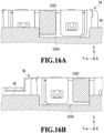
- FIG. 16A is a cross-sectional view of the vicinity of a restriction portion taken along line XVIA-XVIA in FIG. 15A .
- FIG. 16B is a cross-sectional view of the vicinity of the restriction portion taken along line XVIB-XVIB in FIG. 15B .
- FIG. 17 is a diagram schematically showing a cross section of the storage portion 38 that stores the waste ink tank, which cross section is taken along line XVII-XVII in FIG. 15A .
- the storage portion 38 is provided on the other side in the Y direction of the movement area where the print head 22 moves.
- a supply portion 1402 for supplying the print head 22 with ink supplied through the tube 30 is provided on the other side in the Y direction of the carriage 26 on which the print head 22 is mounted.
- the supply portion 1402 can hold the end side of the tube 30 to be connected so as to extend the end side in the X direction.
- the print head 22, the supply portion 1402, and the storage portion 38 are arranged in this order in the Y direction. Through the opening 40, the waste ink tank 34 to be stored in the storage portion 38, the print head 22, the supply portion 1402, and the tube 30 are exposed.
- the print head 22 and the supply portion 1402 move in the X direction via the carriage 26.
- the carriage 26 and the print head 22 and supply portion 1402 that move in the ⁇ X directions as the carriage 26 moves are collectively referred to as a printing unit U.
- the storage portion 38 is provided in a position where the stored waste ink tank 34 does not overlap the printing unit U in the Y direction. Specifically, as shown in FIG. 14 , a gap G is provided between an end position on the other side in the Y direction of the printing unit U (see the two-dot chain line) and an end position on one side in the Y direction of the waste ink tank 34 stored in the storage portion 38 (see the broken line).
- the printing unit U and the waste ink tank 34 overlap each other in the X direction due to the movement of the carriage 26, the printing unit U and the waste ink tank 34 do not contact each other.
- the printing apparatus 10 is provided with a sensor (not shown) capable of detecting the opening and closing of the reader 12, and the opening and closing of the reader 12 is detected by the MPU 302 based on a result of detection by this sensor.
- the MPU 302 retracts the printing unit U to a retracted position (see FIG. 15A ).
- the retracted position is a position where the waste ink tank 34 and an operator do not contact the printing unit U at the time of storing and pulling out the waste ink tank 34 in and from the storage portion 38. It should be noted that the retracted position may coincide with the standby position where the print head 22 (printing unit U) is located while printing is not performed.
- a portion of the waste ink tank 34 in the insertion position is located closer to one side in the Y direction than to the end position (see the two-dot chain line in FIG. 15B ) on the other side in the Y direction of the printing unit U (see the hatched portion in FIG. 15B ).
- the tube 30 that moves in accordance with the movement of the printing unit U is arranged so as not to contact the waste ink tank 34 in the insertion position in a case where the printing unit U is in the retracted position. After that, the operator moves the waste ink tank 34 in the Z direction and pulls out the waste ink tank 34 from the storage portion 38.
- the above procedure is performed reversely. Specifically, with the reader 12 opened and the printing unit U located in the retracted position, an operator moves the waste ink tank 34 with the gripping portion 416 gripped from the upper side of the opening 40 in the -Z direction to the insertion position (see FIG. 15B ). A portion of the waste ink tank 34 in the insertion position is located within the movement area where the printing unit U moves. However, since the printing unit U is in the retracted position, the waste ink tank 34 in the insertion position does not contact the printing unit U and the tube 30. After that, the waste ink tank 34 is moved in the Y direction from the insertion position to the connection position (see FIG. 15A ). As a result, the waste ink tank 34 is stored in the storage portion 38.
- the waste ink tank 34 is provided with a convex portion 1502 protruding in the X direction at the end on the other side in the Z direction and the end on the other side in the X direction in the case of being stored in the storage portion 38.
- the storage portion 38 is provided with a restriction portion 1504 which extends in the Y direction and into which the convex portion 1502 of the waste ink tank 34 can be fitted in a case where the waste ink tank 34 is stored.
- the convex portion 1502 includes a convex portion 420 provided on the side surface 402c provided substantially parallel to a YZ plane of the container portion 402 and a convex portion 422 provided on the other side in the X direction of the lid portion 404 (see FIG. 7 ).
- the convex portion 420 has a predetermined thickness in the Z direction. On the surface of the convex portion 422, there is provided a position index 1508 to cause an operator to recognize the position of the convex portion 1502 using an index 1506 (to be described later).
- the restriction portion 1504 has a concave shape such that the convex portion 1502 can be fitted into the restriction portion 1504 and is configured to restrict the movement of the waste ink tank 34 in the Y direction via the convex portion 1502 to be fitted. Specifically, the restriction portion 1504 restricts the movement in the -Y direction beyond the insertion position of the waste ink tank 34 at one end on one side in the Y direction of the restriction portion 1504 (see FIG. 16B ). As a result, it is possible to suppress the contact of the waste ink tank 34 moved in the -Y direction with the tube 30.
- the restriction portion 1504 restricts the movement of the waste ink tank 34 in the Y direction beyond the connection position at the other end on the other side in the Y direction of the restriction portion 1504 (see FIG. 16A ). That is, in the storage portion 38, the restriction portion 1504 restricts, via the convex portion 1502, the upstream side in the Y direction of the movement area where the waste ink tank 34 moves in the insertion position and the other side in the Y direction in the connection position.
- the index 1506 is provided in a position adjacent to the restriction portion 1504 in the storage portion 38. Specifically, a first index 1506a indicating that the waste ink tank 34 can be pulled out is provided in a position corresponding to the position index 1508 in a case where the convex portion 1502 is in the insertion position in the restriction portion 1504. Further, a second index 1506b indicating that the waste ink tank 34 is connected (fixed) is provided in a position corresponding to the position index 1508 in a case where the convex portion 1502 is in the connection position in the restriction portion 1504.
- the convex portion 1502 is located at the other end of the restriction portion 1504, and the position index 1508 is located in a position corresponding to the second index 1506b (see FIG. 15A ). Specifically, the position index 1508 and the second index 1506b are aligned in the X direction. Further, in a case where the waste ink tank 34 in the storage portion 38 is in the insertion position, the convex portion 1502 is located at one end of the restriction portion 1504, and the position index 1508 is located in a position corresponding to the first index 1506a (see FIG. 15B ).
- the position index 1508 and the first index 1506a are aligned in the X direction.
- an operator can easily determine whether the waste ink tank 34 in the storage portion 38 is in the connection position or the insertion position and whether the waste ink tank 34 can be pulled out from the storage portion 38.
- the position index 1508 is provided in the convex portion 1502, it is possible to downsize the waste ink tank 34 as compared with a case where the position index 1508 and the convex portion 1502 are provided separately.
- restriction of the movement of the waste ink tank 34 in the Y direction does not have to be performed using the restriction portion 1504 and the convex portion 1502, and various publicly-known techniques can be used. Additionally, the convex portion 1502, the restriction portion 1504, and the index 1506 are provided on the other side in the X direction of the waste ink tank 34 stored in the storage portion 38 but may be provided on the one side in the X direction of the waste ink tank 34.
- the storage portion 38 is provided with a latch mechanism 1702 capable of drawing in and fixing the waste ink tank 34 moved to the vicinity of the connection position to the connection position. This makes it easier for an operator to move the waste ink tank 34 to the connection position and suppresses a careless movement of the waste ink tank 34 from the connection position.
- the latch mechanism 1702 functions as a fixing mechanism that fixes the waste ink tank 34 stored in the storage portion 38. It should be noted that such a fixing mechanism is not limited to the latch mechanism 1702, and various publicly-known techniques can be used.
- FIGs. 18A and 18B are diagrams for explaining a procedure for replacing the print head 22.
- FIG. 18A shows a state where the printing unit U is located in a replacement position
- FIG. 18B is a diagram showing a state where the supply portion 1402 is removed from the print head 22.
- the print head 22 is replaced with the reader 12 opened and the waste ink tank 34 pulled out from the storage portion 38.
- the operation portion 16 or the like is operated to provide an input to start an operation to replace the print head 22.
- the MPU 302 moves the printing unit U to the replacement position.
- the replacement position is a position where the supply portion 1402 is accommodated within storage space Sp in the X direction (see FIG. 18A ).
- the supply portion 1402 is removed from the print head 22 in the printing unit U in the replacement position.
- the supply portion 1402 is configured such that the needle 1802 can be inserted into and removed from the print head 22.
- the tube 30 is communicated with the needle 1802, and ink supplied from the tube 30 flows into the needle 1802.
- the print head 22 is supplied with ink via the needle 1802.
- the needle 1802 is inserted into or pulled out from the print head 22 by opening and closing a lever portion 1804.
- the lever portion 1804 must be opened to remove the supply portion 1402 from the print head 22.
- the supply portion 1402 moves in the Y direction, and the needle 1802 is pulled out from the print head 22 mounted on the carriage 26 (see FIG. 18B ).
- a portion of the supply portion 1402 is located within the storage space Sp in the storage portion 38.
- the print head 22 is removed from the carriage 26 and a new print head 22 is mounted on the carriage 26.
- the lever portion 1804 is then closed, and the supply portion 1402 is moved in the -Y direction. As a result, the needle 1802 is inserted into the print head 22 after replacement mounted on the carriage 26.
- the movement area where the printing unit U moves overlaps a portion of the movement area at the time of replacing of the waste ink tank 34 in the storage portion 38.
- the movement of the waste ink tank 34 during replacement is restricted, and this configuration is used to allow an operator to recognize the position of the waste ink tank 34 during the replacement.
- a portion of a movement area where the supply portion that supplies the print head 22 with ink moves overlaps the storage area of the waste ink tank 34 of the storage portion 38.
- a technique capable of certainly suppressing adhesion of waste ink to hands, clothes, and the like during replacement of a waste ink tank (34) is provided.
- a container portion (402) provided with an insertion port (408) which a discharge member (950) discharging waste ink can be inserted into and pulled out from and a shielding portion (414) movable between a shielding position where the insertion port is shielded and an open position where the insertion port is opened.
Landscapes
- Ink Jet (AREA)
Abstract
Description
- The present invention relates to a printing apparatus with a waste ink tank that reserves waste ink and is provided replaceably in the apparatus.
- A printing apparatus that ejects ink to perform printing includes a recovery portion for maintaining and recovering ink ejection performance satisfactorily. In such a printing apparatus, a waste ink tank for storing waste ink received in the recovery portion is provided replaceably.
-
Japanese Patent Laid-Open No. 2021-109415 - However, in the technique disclosed in
Japanese Patent Laid-Open No. 2021-109415 - The present invention provides a waste ink tank that can be replaced properly.
- The present invention in its first aspect provides a printing apparatus as specified in
claims 1 to 15. - According to the present invention, it is possible to replace a waste ink tank properly.
- Further features of the present invention will become apparent from the following description of exemplary embodiments with reference to the attached drawings.
-
-
FIGs. 1A and 1B are schematic configuration diagrams of a printing apparatus; -
FIG. 2 is a schematic configuration diagram of a recovery portion and a waste ink tank; -
FIG. 3 is a block diagram showing a configuration of a control system for the printing apparatus; -
FIG. 4 is a perspective configuration diagram of the waste ink tank; -
FIGs. 5A and 5B are diagrams showing an example of an insertion portion; -
FIGs. 6A and 6B are diagrams showing another form of the insertion portion; -
FIG. 7 is an exploded perspective view of the waste ink tank; -
FIGs. 8A and 8B are diagrams showing the waste ink tank with a shielding portion located in a shielding position and an open position; -
FIG. 9 is a perspective configuration diagram of a frame portion; - 10A to 10C are diagrams showing a positional relationship between the waste ink tank and the frame portion in an insertion position;
-
FIGs. 11A to 11C are diagrams showing a positional relationship between the waste ink tank and the frame portion in a storage position; -
FIG. 12 is a plan view of the waste ink tank showing an example of a gripping portion; -
FIGs. 13A and 13B are diagrams showing another form of the gripping portion; -
FIG. 14 is a diagram showing a state where a printing unit and the waste ink tank are exposed from an opening; -
FIGs. 15A and 15B are diagrams for explaining replacement of the waste ink tank; -
FIGs. 16A and 16B are diagrams for explaining restriction, by a convex portion, of movement of the waste ink tank; -
FIG. 17 is a diagram showing a fixing mechanism for the waste ink tank; and -
FIGs. 18A and 18B are diagrams for explaining replacement of a print head. - A description will be given of an example of embodiments for a printing apparatus in detail below with reference to the accompanying drawings. It should be noted that the following embodiments do not limit the present invention, and not all combinations of features described in the present embodiment are essential to a solution to the problem to be solved by the present invention. Further, the positions, shapes, and the like of the constituent elements described in the embodiments are merely examples and are not intended to limit the scope of the present invention only to them.
- A printing apparatus with a waste ink tank according to the present embodiment may be an apparatus having only the function of printing an image on a print medium, or a multifunction device having the function of reading an image. In the following description, a multifunction device that has the function of reading an image and can print an image on a print medium will be described as an example of the printing apparatus with the waste ink tank according to the present embodiment.
-
FIGs. 1A and 1B are configuration diagrams of the printing apparatus according to the present embodiment.FIG. 1A is an external view of the printing apparatus with a reader opened andFIG. 1B is a schematic configuration diagram of a main portion of a printing portion.FIG. 2 is a schematic configuration diagram of a recovery portion and the waste ink tank. - Here, directions used in the present specification will be described. In the present specification, description will be given on the assumption that in a case where an operator faces the printing apparatus, a direction from a left side to a right side of the apparatus is an X direction, a direction from a back side to a front side is a Y direction, and a direction from a lower side to an upper side is a Z direction. Thus, the X direction, Y direction, and Z direction are directions from one side to the other side and will be indicated with "+ (plus)" as appropriate, and the X direction, Y direction, and Z direction from the other side to one side will be indicated with "- (minus)."
- A
printing apparatus 10 includes areader 12 capable of reading an image on a document, aprinting portion 14 capable of printing an image on a print medium based on image data, and anoperation portion 16 that receives an input of an instruction from a user and can display various kinds of information. Thereader 12 is provided above theprinting portion 14 so as to be openable and closable. Incidentally, since various publicly-known techniques can be used for the configurations of thereader 12 and theoperation portion 16, the detailed descriptions thereof will be omitted in the following description. - The
printing portion 14 includes aconveyance roller 18 that conveys a fed print medium, aplaten 20 that supports the print medium conveyed by theconveyance roller 18, and aprint head 22 that ejects ink onto the print medium supported by theplaten 20 to perform printing. Theprinting portion 14 also includes adischarge roller 23 that discharges the print medium printed by theprint head 22 to a tray (not shown). - The
printing portion 14 includes apinch roller 24 that is pressed against and is associated with theconveyance roller 18, and a print medium is pinched between theconveyance roller 18 and thepinch roller 24 and can be conveyed in the ±Y directions. Theprint head 22 is detachably mounted on acarriage 26 provided movably in the ±X directions. Accordingly, in theprinting portion 14, theprint head 22 is configured to be movable in the ±X directions via thecarriage 26. Theplaten 20 extends in the X direction a length corresponding to the length in a width direction of a printable print medium. - After a print medium is conveyed to a print start position by the
conveyance roller 18, theprinting portion 14 performs a printing operation in which ink is ejected onto the print medium while theprint head 22 is moved in the X direction (or the -X direction) to perform printing. Next, a conveyance operation in which theconveyance roller 18 conveys the print medium by a predetermined amount in the Y direction is performed, an unprinted area is located in a position opposite to theprint head 22, and the printing operation is performed again. Alternately and repeatedly executing the printing operation and the conveyance operation in this way, the print medium is printed in theprinting portion 14. - The
printing portion 14 includes anink tank 28 that stores ink to be supplied to theprint head 22 on the other side in the Y direction. Theink tank 28 is connected to theprint head 22 through atube 30, and ink stored in theink tank 28 is supplied to theprint head 22 through thetube 30. In a position opposite to theprint head 22 in a standby position, theprinting portion 14 also includes arecovery portion 32 that executes a recovery operation for maintaining and recovering the ink ejection performance of theprint head 22 satisfactorily. Incidentally, the standby position is a position where theprint head 22 is on standby while printing is not performed and is, for example, a position near the end on the other side in the X direction in an area where theprint head 22 moves including the carriage 26 (hereinafter simply referred to as "the movement area where theprint head 22 moves" or "the movement area where a printing unit U moves (to be described later)"). Theprinting portion 14 further includes awaste ink tank 34 into which waste ink received at therecovery portion 32 is discharged. In the present embodiment, thewaste ink tank 34 is stored in astorage portion 38 provided adjacent to the movement area where theprint head 22 moves in a print medium conveyance direction, more specifically, adjacent to the other side in the Y direction of the movement area. - The
recovery portion 32 includes acap 202 that caps and protects an ejection port surface where an ink ejection port through which ink is ejected is formed in theprint head 22, awiper 204 for wiping off a deposit deposited on the ejection port surface, and asuction pump 206 for reducing pressure in the cap 202 (seeFIG. 2 ). In the present embodiment, since black ink and color ink are ejected, thecap 202 includes a cap corresponding to an ejection port for ejecting black ink and a cap corresponding to an ejection port for ejecting color ink. - The
suction pump 206 is connected to a dischargingtube 208. The dischargingtube 208 is connected at one end to thesuction pump 206 and at the other end to thewaste ink tank 34 via aconnection portion 210. That is, therecovery portion 32 is connected to thewaste ink tank 34 via the dischargingtube 208. In theprinting portion 14, waste ink received at therecovery portion 32 by, for example, executing various recovery operations is discharged to thewaste ink tank 34 through the dischargingtube 208. Theconnection portion 210 is provided with a needle portion 950 (seeFIG. 9 ) and thisneedle portion 950 is inserted into an insertion port 408 (to be described later) of thewaste ink tank 34, so that the dischargingtube 208 is connected to thewaste ink tank 34. - The upper surface of the
printing portion 14 is formed by a cover member 36 (seeFIG. 1A ). Thus, in theprinting apparatus 10, in a case where thereader 12 is opened, thecover member 36 is exposed to the outside. In thecover member 36, there is formed anopening 40 through which a portion of the movement area where theprint head 22 moves and thestorage portion 38 that stores thewaste ink tank 34 are exposed. In theopening 40, the size of a portion where a portion of the movement area where theprint head 22 moves is exposed is large enough for a user to put the user's hand into the movement area where theprint head 22 moves or the like to remove a print medium, for example, in a case where paper-jamming (paper jam) occurs. In theopening 40, a portion where thestorage portion 38 is exposed is large enough to insert thewaste ink tank 34 into thestorage portion 38 in the -Z direction (gravitational direction). Thestorage portion 38 is located on the other side in the Y direction of the movement area where theprint head 22 moves and on one side in the X direction of the movement area. Thus, in theprinting apparatus 10, in a case where thereader 12 is opened, thewaste ink tank 34 is located in front of the movement area where theprint head 22 moves, and a worker such as a user, a repairman, etc. can easily replace thewaste ink tank 34. - Next, the configuration of a control system for the
printing apparatus 10 will be described.FIG. 3 is a block diagram showing the configuration of the control system for theprinting apparatus 10. Incidentally,FIG. 3 shows a main configuration with a focus on theprinting portion 14 of theprinting apparatus 10. - The
printing apparatus 10 includes anMPU 302 that controls all operations in theprinting apparatus 10, such as the operation of each constituent and data processing, and aROM 304 that stores various programs and various kinds of data executed by theMPU 302. Theprinting apparatus 10 also includes aRAM 306 that temporarily stores processing data executed by theMPU 302 and data received from a host computer 300 (to be described later). - The
MPU 302 is connected to aprint head driver 308 to control driving of theprint head 22 via theprint head driver 308. TheMPU 302 is also connected to acarriage motor driver 310 to control, via thecarriage motor driver 310, driving of acarriage motor 312 that moves thecarriage 26. Further, theMPU 302 is connected to aconveyance motor driver 314 to control, via theconveyance motor driver 314, driving of aconveyance motor 316 that drives theconveyance roller 18 and thedischarge roller 23. Furthermore, theMPU 302 is connected to asuction motor driver 318 to control asuction motor 320 that drives thesuction pump 206 via thesuction motor driver 318. - The
MPU 302 is connected to an interface (I/F)portion 322 and is connected to thehost computer 300 via the I/F portion 322. Thehost computer 300 is provided with adriver 324 for collecting print information such as a print image and print quality and communicating with theprinting apparatus 10 in a case where instructions to start printing are given by a user. TheMPU 302 is also connected to adisplay portion 328 to control display on theoperation portion 16 via thedisplay portion 328. Further, theMPU 302 is connected to adetection portion 330 capable of detecting the amount of waste ink discharged to thewaste ink tank 34. Based on a result of detection by thedetection portion 330, theMPU 302 makes a notification to, for example, prompt for replacement of thewaste ink tank 34 via thedisplay portion 328. - Next, the configuration of the
waste ink tank 34 will be described in detail.FIG. 4 is a perspective configuration diagram of thewaste ink tank 34. In the present specification, in the figures showing thewaste ink tank 34, the X direction, Y direction, and Z direction in the figures indicate directions in the case of storing thewaste ink tank 34 in thestorage portion 38. Thewaste ink tank 34 is replaced with a newwaste ink tank 34 by an operator based on, for example, a notification displayed on theoperation portion 16 to prompt for replacement of thewaste ink tank 34. - The
waste ink tank 34 includes a substantially box-shaped container portion 402 (seeFIG. 7 ) with a top opened and alid portion 404 detachably fixed to thecontainer portion 402 so as to cover the top opening of thecontainer portion 402. Thewaste ink tank 34 also includes an absorbent 406 (seeFIG. 7 ) that is contained in thecontainer portion 402 and capable of absorbing waste ink. - The
container portion 402 is provided with theinsertion port 408 opened so that the needle portion 950 (seeFIG. 9 ) provided in the connection portion 210 (seeFIG. 2 ) can be inserted and pulled out on aside surface 402a located on the other side in the Y direction in a case where thewaste ink tank 34 is stored in thestorage portion 38. Incidentally, the absorbent 406 contained in thecontainer portion 402 is exposed from the opening of theinsertion port 408. In the present embodiment, twoinsertion ports 408 are provided along the X direction. Theneedle portion 950 for discharging black waste ink is inserted into oneinsertion port 408, and theneedle portion 950 for discharging color waste ink is inserted into theother insertion port 408. - Here, although details will be described later, in the case of storing the
waste ink tank 34 in thestorage portion 38, first, thewaste ink tank 34 is inserted in the -Z direction from a position corresponding to thestorage portion 38 of theopening 40. After that, thewaste ink tank 34 is moved in the Y direction, and theneedle portion 950 is inserted into theinsertion port 408. That is, in the present embodiment, in a case where thewaste ink tank 34 is stored in thestorage portion 38, theneedle portion 950 of theconnection portion 210 is inserted into theinsertion port 408. Waste ink is then discharged from theneedle portion 950 into thecontainer portion 402 through the dischargingtube 208, and the discharged waste ink is absorbed into the absorbent 406. As described above, in the present embodiment, theneedle portion 950 functions as a discharge member that discharges waste ink to thewaste ink tank 34. - Further, the
side surface 402a of thecontainer portion 402 is provided with aconnection terminal 412 that can be electrically connected to a connection terminal (not shown) provided in thestorage portion 38 in a case where thewaste ink tank 34 is stored in thestorage portion 38. Theconnection terminal 412 is provided closer to one side in the Z direction than to theinsertion port 408 and in a position different from that of theinsertion port 408 in the X direction. Thus, even in a case where waste ink leaks from theinsertion port 408, the leaking waste ink does not easily reach theconnection terminal 412. TheMPU 302 detects that thewaste ink tank 34 is stored in thestorage portion 38 by detecting that the connection terminal in thestorage portion 38 is connected to theconnection terminal 412 based on a result of detection by thedetection portion 330. On the other hand, theMPU 302 detects that thewaste ink tank 34 is removed from thestorage portion 38 by detecting that the connection between the connection terminal in thestorage portion 38 and theconnection terminal 412 is released based on a result of detection by thedetection portion 330. In the case of detecting that awaste ink tank 34 is newly stored in thestorage portion 38, theMPU 302 stores the amount of waste ink stored in the newly attachedwaste ink tank 34. - A shielding
portion 414 capable of shielding and opening theinsertion port 408 is provided on theside surface 402a of thecontainer portion 402. The shieldingportion 414 is configured to be movable between a shielding position and an open position. The shieldingportion 414 shields theinsertion port 408 from the outside by being located in the shielding position where theinsertion port 408 is shielded. As a result, the absorbent 406 exposed from theinsertion port 408 is shielded from the outside. In addition, the shieldingportion 414 brings about a state where theinsertion port 408 is exposed by being located in the open position where theinsertion port 408 is opened. As a result, the absorbent 406 is exposed to the outside from theinsertion port 408. - The
lid portion 404 is provided with anopening 410 for accelerating the evaporation of waste ink absorbed into the absorbent 406 inside thecontainer portion 402. Thelid portion 404 includes, for example, a plurality ofhole sections 404a that can be fitted to a plurality ofclaw portions 402b provided in the container portion 402 (seeFIG. 7 ). Thehole sections 404a are fitted to theclaw portions 402b, so that thelid portion 404 is fixed to the container portion 402 (seeFIG. 4 ). Incidentally, a fixing mechanism for fixing thelid portion 404 to thecontainer portion 402 is not limited to this. In thelid portion 404, a grippingportion 416 that can be gripped by an operator is formed. The operator thus can grip the grippingportion 416 of thelid portion 404 fixed to thecontainer portion 402 to move thewaste ink tank 34. - Next, the absorbent 406 loaded in the
container portion 402 will be described.FIGs. 5A and 5B are diagrams showing an insertion portion provided in the absorbent 406 located within an opening area of theinsertion port 408.FIG. 5A is a schematic configuration diagram of the insertion portion andFIG. 5B is a diagram showing a state where theneedle portion 950 is inserted into the insertion portion. It should be noted that the X direction, Y direction, and Z direction in the figures indicate directions in a case where thewaste ink tank 34 is stored in thestorage portion 38. Incidentally,FIG. 5B shows that the absorbent 406 is located only in a partial area in thecontainer portion 402 in the vicinity of theinsertion port 408 in order to facilitate understanding. That is, the absorbent 406 near theinsertion port 408 is not limited to the form shown inFIG. 5B . - The absorbent 406 is arranged inside the
container portion 402 so as to be able to absorb waste ink discharged through theneedle portion 950. The absorbent 406 is also formed with aninsertion portion 502 through which theneedle portion 950 can be inserted in a position corresponding to an opening area S1 of theinsertion port 408, that is, in a position including a portion exposed from theinsertion port 408. - The
insertion portion 502 has a size large enough to cover the entire opening area S1 and is formed of a plurality oflinear cuts 504 that intersect with each other in a center position P1 of the opening area S1. In theinsertion portion 502, alinear cut 508 along a direction in which a bucklingportion 506 extends is formed in the center position of each bucklingportion 506 that buckles in a case where theneedle portion 950 is inserted. Incidentally, in theinsertion portion 502, thecut 508 is formed in a position in contact with the opening area S1 (the position shown inFIG. 5A ) or is formed outside the opening area S1. For example, in a case where twocuts 504 are formed in a substantially cross shape in theinsertion portion 502, thecut 508 is formed along the direction in which the bucklingportion 506 extends in the center position of the bucklingportion 506 connecting adjacent ends of the cut 504 (seeFIG. 5A ). Incidentally, the length of thecut 508 is shorter than the length of the bucklingportion 506 in which thecut 508 is formed (a length between the adjacent ends of the cut 504). - As a result, in a case where the
needle portion 950 is inserted from theinsertion port 408, theneedle portion 950 inserted from the vicinity of the center position P1 presses theinsertion portion 502 in the -Y direction. As a result, a plurality of substantially triangular areas formed by thecuts 504 in theinsertion portion 502 are deformed while contacting theneedle portion 950 and bend in the -Y direction at the bucklingportion 506 as shown inFIG. 5B . At this time, since thecut 508 is formed in the center position of the bucklingportion 506, theinsertion portion 502 can be easily bent in the -Y direction, and a load generated at the time of insertion of theneedle portion 950 is reduced. - It should be noted that the
insertion portion 502 does not have to be formed by thecuts insertion portion 502 may have any shape as long as there is formed a reduction portion capable of reducing a load to be generated on theneedle portion 950 in a case where theneedle portion 950 is inserted. In the above description, thecut 508 corresponds to the reduction portion. - An insertion portion 502' in another form is, for example, formed of a substantially polygonal
first opening 602 and substantially rectangularsecond openings 604 formed in positions corresponding to respective sides of thefirst opening 602, specifically, at predetermined distances from the respective sides (seeFIGs. 6A and 6B). FIGs. 6A and 6B are diagrams showing the insertion portion 502'.FIG. 6A is a schematic configuration diagram of the insertion portion 502' andFIG. 6B is a diagram showing the insertion portion 502' deformed due to the insertion of theneedle portion 950. InFIGs. 6A and 6B , as inFIGs. 5A and 5B , the X direction, Y direction, and Z direction in the figures indicate directions in a case where thewaste ink tank 34 is stored in thestorage portion 38. - The
first opening 602 is formed so that the center position thereof substantially coincides with the center position P1 of the opening area S1 and at least a portion of each side is located within theopening area S 1. As shown inFIG. 6A , thefirst opening 602 has, for example, a substantially square shape. - The
second opening 604 is provided on an extension of a direction in which thefirst opening 602 is deformed (hereinafter also referred to as "deformation direction") in a case where theneedle portion 950 is inserted into the insertion portion 502'. An interval between thesecond opening 604 and thefirst opening 602 is an interval such that a gap portion gm between thesecond opening 604 and thefirst opening 602 can be deformed as a whole in the deformation direction in a case where theneedle portion 950 is inserted into the insertion portion 502'. The length Ls of a short side of the substantially rectangularsecond opening 604 is preferably equal to or greater than the deformation amount Δd of the gap portion gm in a case where theneedle portion 950 is inserted into the insertion portion 502'. Further, the length Ll of a long side of thesecond opening 604 is, for example, substantially equal to the length of a corresponding side of thefirst opening 602. Incidentally, the shape of thesecond opening 604 is not limited to a substantially rectangular shape and may be any shape as long as the gap portion gm after deformation in a case where theneedle portion 950 is inserted does not contact the inside of an opening in thesecond opening 604. That is, in the insertion portion 502', the length of thesecond opening 604 in a direction in which a corresponding side of thefirst opening 602 is deformed in a case where theneedle portion 950 is inserted is preferably equal to or greater than the deformation amount Δd of the gap portion gm. - Such a configuration, in a case where the
needle portion 950 is inserted from theinsertion port 408, causes theneedle portion 950 inserted from the vicinity of the center position P1 to press each side of thefirst opening 602 in a direction away from the center position P1 (the deformation direction described above). As a result, the gap portion gm is deformed in the direction away from the center position P1 while contacting theneedle portion 950. Here, thesecond opening 604 is provided on an extension of the direction in which the gap portion gm is deformed, and the length of thesecond opening 604 in the direction of deformation, that is, the length of the short side Ls is equal to or greater than the deformation amount Δd of the gap portion. Thus, the deformation of the gap portion gm is absorbed by thesecond opening 604. As a result, the insertion portion 502' is easily deformed in a case where theneedle portion 950 is inserted, and a load to be generated on theneedle portion 950 at the time of insertion into theinsertion port 408 is reduced. That is, in this case, thesecond opening 604 corresponds to the reduction portion that reduces a load to be generated on theneedle portion 950 at the time of insertion. - Next, the shielding
portion 414 will be described. The shieldingportion 414 is configured to be movable between the shielding position and the open position as described above. Specifically, in a case where thewaste ink tank 34 is not stored in thestorage portion 38, the shieldingportion 414 is located in the shielding position. In a case where thewaste ink tank 34 is stored in thestorage portion 38, the shieldingportion 414 is moved from the shielding position to the open position by a frame portion 900 (to be described later) provided in thestorage portion 38. Further, in a case where thewaste ink tank 34 is pulled out from thestorage portion 38, the shieldingportion 414 is separated from theframe portion 900 and moves from the open position to the shielding position. The configurations of the shielding portion 414 (including a moving mechanism) and theframe portion 900 and the operation of the shieldingportion 414 will be described below. Configurations of the Shielding Portion and the Moving Mechanism of the Shielding Portion -
FIG. 7 is an exploded diagram of thewaste ink tank 34.FIG. 8A is a perspective view of thewaste ink tank 34 with the shieldingportion 414 located in the shielding position andFIG. 8B is a perspective view of thewaste ink tank 34 with the shieldingportion 414 located in the open position. - A holding
portion 700 capable of holding the shieldingportion 414 movably in the Z direction is formed on theside surface 402a of thecontainer portion 402. The shieldingportion 414 is arranged on theside surface 402a of thecontainer portion 402 while being held by the holdingportion 700. - The holding
portion 700 includes arib 702 extending in the Z direction, a pair ofconvex portions 704 formed at an interval in the Z direction and protruding in the Y direction, and aspring receiving portion 706 that receives aspring 714 held between the holdingportion 700 and the shieldingportion 414. The shieldingportion 414 includes agroove portion 708 that extends in the Z direction and can be fitted to therib 702, an abuttingportion 710 that is arranged between the pair ofconvex portions 704 and abuts against the pair ofconvex portions 704 at the time of the movement of the shieldingportion 414 in the ±Z directions, and aspring receiving portion 712 that receives thespring 714. The shieldingportion 414 also includes a shieldingmember 716 that shields theinsertion port 408 and anengagement portion 718 that engages theframe portion 900 in the case of storing thewaste ink tank 34 in thestorage portion 38. - In a case where the shielding
portion 414 is held by the holdingportion 700, thespring 714 is held by thespring receiving portion 706 and thespring receiving portion 712. Thespring 714 is arranged in thespring receiving portion 706 and thespring receiving portion 712 so as to bias the shieldingportion 414 in the -Z direction (predetermined direction). Further, thegroove portion 708 is fitted to therib 702 with the abuttingportion 710 located between the pair ofconvex portions 704. - The abutting
portion 710 between the pair ofconvex portions 704 restricts movement of the shieldingportion 414 in the ±Z directions beyond a predetermined range including the shielding position and the open position. Specifically, the shieldingportion 414 is always biased in the -Z direction by thespring 714 and thus is located in the shielding position where the shieldingmember 716 shields the insertion port 408 (seeFIG. 8A ) unless a force in the Z direction acts on the shieldingportion 414. In this shielding position, the abuttingportion 710 contacts oneconvex portion 704a located on one side in the Z direction of the pair ofconvex portions 704, so that the movement of the shieldingportion 414 in the -Z direction beyond the shielding position is restricted. On the other hand, in a case where a force in the Z direction is applied to the shieldingportion 414, the shieldingportion 414 moves in the Z direction against the biasing force of thespring 714 in the -Z direction and is located in the open position where the shielding of theinsertion port 408 by the shieldingmember 716 is released (seeFIG. 8B ). In this open position, the abuttingportion 710 contacts the otherconvex portion 704b located on the other side in the Z direction of the pair ofconvex portions 704, so that the movement of the shieldingportion 414 in the Z direction beyond the open position is restricted. As described above, in the present embodiment, the pair ofconvex portions 704 functions as a restriction member that restricts the movement of the shieldingportion 414 in the -Z direction beyond the shielding position and also restricts the movement of the shieldingportion 414 in the Z direction beyond the open position. - Further, movement in the Y direction is restricted by fitting the
rib 702 into the groove portion708. It should be noted that the shieldingportion 414 is provided in a portion where a step in the Y direction of thecontainer portion 402 is formed, and movement in the X direction is restricted by the shape of the step, the pair ofconvex portions 704, the abuttingportion 710, and the like. The engagement relationship between the shieldingportion 414 and the holdingportion 700 is not limited to the configuration described above, and various publicly-known techniques can be used. - Next, descriptions will be given of the configuration of the frame portion provided in the
storage portion 38 and the operation of the shieldingportion 414 in a case where thewaste ink tank 34 is mounted on the frame portion. The frame portion has the function of guiding thewaste ink tank 34 moved in the -Z direction, inserted into thestorage portion 38, and located in the insertion position to a connection position where thewaste ink tank 34 is connected to theneedle portion 950 of theconnection portion 210 and the function of moving the shieldingportion 414 from the shielding position to the open position. -
FIG. 9 is a perspective configuration diagram of theframe portion 900 provided in thestorage portion 38. Theframe portion 900 includes amain body portion 902 to and from which thewaste ink tank 34 can be attached and detached and acover 904 provided on the other side in the Z direction of themain body portion 902. Incidentally, inFIG. 9 , the shape of thecover 904 is shown in a simplified manner to facilitate understanding. - The
main body portion 902 includes aguide portion 905 that extends in the Y direction and can guide the movement of thewaste ink tank 34 between the insertion position and the connection position and an erectedportion 906 that is erected on the other side in the Y direction of theguide portion 905. Theguide portion 905 includes aguide groove 908 into which a guide 720 (seeFIG. 7 ) provided in thewaste ink tank 34 is inserted and anengagement portion 910 that engages the shieldingportion 414 between the insertion position and the connection position of thewaste ink tank 34. In the erectedportion 906, theconnection portion 210 is held so that theneedle portion 950 is properly inserted into theinsertion port 408 in a case where thewaste ink tank 34 with the shieldingportion 414 being in the open position moves to the connection position. - The
cover 904 is configured to cover the upper side of theconnection portion 210 arranged in themain body portion 902. That is, thecover 904 covers the connection portion of theconnection portion 210 at the erectedportion 906 and the upper side of the exposedneedle portion 950. Incidentally, thecover 904 may be formed integrally with themain body portion 902 or may be provided separately from themain body portion 902. In the case of being formed separately, thecover 904 may, for example, be fixedly connected to thecover member 36 or may be connected revolvably about an axis parallel to the X direction. Incidentally, InFIGs. 1A and 1B , an illustration of thecover 904 is omitted. -
FIGs. 10A to 10C are diagrams showing thewaste ink tank 34 and theframe portion 900 in the insertion position.FIG. 10A is a perspective view seen from above,FIG. 10B is a plan view, andFIG. 10C is a perspective view seen from below.FIGs. 11A to 11C are diagrams showing thewaste ink tank 34 and theframe portion 900 in the connection position.FIG. 11A is a perspective view seen from above,FIG. 11B is a plan view, andFIG. 11C is a perspective view seen from below. Incidentally, inFIG. 10A andFIG. 11A , thecover 904 is omitted to facilitate understanding. Additionally,FIGs. 10B and 10C andFIGs. 11B and 11C show the shape of thecover 904 in a simplified manner to facilitate understanding. Further, inFIG. 10C andFIG. 11C , themain body portion 902 is omitted to facilitate understanding. - In a case where the
waste ink tank 34 is inserted into thestorage portion 38 from theopening 40 while moving in the -Z direction and is arranged in the insertion position in thestorage portion 38, the positional relationship between theframe portion 900 and thewaste ink tank 34 provided in thestorage portion 38 is as shown inFIG. 10A . - Specifically, at the time of arrangement in the insertion position, an operator first grips the
gripping portion 416 with the operator's fingers, inserts thewaste ink tank 34 into thestorage portion 38 from theopening 40 in the -Z direction, and fits theguide 720 of thewaste ink tank 34 into theguide groove 908 of theframe portion 900. At this time, theengagement portion 718 of the shieldingportion 414 engages theengagement portion 910 of theframe portion 900. The operator then removes the operator's fingers from the grippingportion 416. Here, the biasing force of thespring 714 is smaller than a force in the -Z direction generated under the weight of thewaste ink tank 34. Thus, in a case where the fingers are released from the grippingportion 416, the shieldingportion 414 maintains the position thereof in the Z direction, while thecontainer portion 402 moves in the -Z direction. That is, the shieldingportion 414 moves in the Z direction relatively with respect to thecontainer portion 402. As a result, the shieldingportion 414 is located in the open position and theinsertion port 408 is opened. Although a case where the shieldingportion 414 is located in the open position under the weight of thewaste ink tank 34 has been described, the present invention is not limited to this, and an operator may locate the shieldingportion 414 in the open position by pressing thewaste ink tank 34 in the -Z direction. - In the insertion position, the
waste ink tank 34 is separated from thecover 904 in the Y direction (seeFIG. 10B ). In the insertion position, theneedle portion 950 is separated from theinsertion port 408 and is not inserted (seeFIG. 10C ). - After the
waste ink tank 34 is located in the insertion position, an operator moves thewaste ink tank 34 in the Y direction. As a result, thewaste ink tank 34 is moved in the Y direction while being guided by theguide portion 905, and theneedle portion 950 of theconnection portion 210 fixed to the erectedportion 906 is inserted into the insertion port 408 (seeFIG. 11A ). Thewaste ink tank 34 is then moved and fixed to a position where theneedle portion 950 is properly inserted into theinsertion port 408, that is, the connection position where waste ink discharged from theneedle portion 950 does not leak from theinsertion port 408. A fixing mechanism for thewaste ink tank 34 will be described later. Theconnection terminal 412 of thewaste ink tank 34 is connected to the connection terminal provided in thestorage portion 38 in the connection position. As a result, theMPU 302 detects that a newwaste ink tank 34 has been mounted and stores the amount of waste ink contained in the newly attachedwaste ink tank 34. - In the connection position, the
waste ink tank 34 is adjacent to thecover 904 in the Y direction (seeFIG. 11B ). In the connection position, thewaste ink tank 34 has a partial area on the other side in the Y direction where theinsertion port 408 and the shieldingportion 414 are located (see the broken line portion inFIG. 11B ), the upper side of the partial area being covered with thecover 904. That is, thecover 904 is provided so as to overlap a portion of thewaste ink tank 34 in the connection position in the Y direction. Further, the shape of theside 904a of thecover 904 on one side in the Y direction adjacent to thewaste ink tank 34 corresponds to the shape of the adjacentwaste ink tank 34 in the connection position. In thewaste ink tank 34 in the connection position, for example, the upper surface of thelid portion 404 and thecover member 36 coincide with each other in the Z direction, or the upper surface of thelid portion 404 is located closer to one side (lower side) in the Z direction than to thecover member 36 by a certain amount. - In the case of pulling out the
waste ink tank 34 from thestorage portion 38, the above procedure is performed reversely. Specifically, an operator first grips thegripping portion 416 and moves thewaste ink tank 34 in the -Y direction. As a result, thewaste ink tank 34 moves from the connection position to the insertion position. At this time, although theneedle portion 950 is pulled out from theinsertion port 408, theinsertion portion 502 of the absorbent 406 is located in the opening area S1 of theinsertion port 408, and theneedle portion 950 is pulled out while contacting theinsertion portion 502. Thus, ink is less likely to leak out of theinsertion port 408. - After that, the
waste ink tank 34 is moved in the Z direction and is pulled out from thestorage portion 38. After thewaste ink tank 34 is moved in the Z direction from the insertion position, theengagement portion 718 of the shieldingportion 414 is separated from theengagement portion 910 of theframe portion 900, so that the biasing force of thespring 714 moves the shieldingportion 414 in the -Z direction relatively with respect to thecontainer portion 402. As a result, the shieldingportion 414 moves from the open position to the shielding position. Accordingly, in a case where thewaste ink tank 34 is pulled out from thestorage portion 38, theinsertion port 408 is shielded by the shieldingportion 414, so that the operator cannot easily contact theinsertion port 408 of thewaste ink tank 34 pulled out, which suppresses adhesion of ink to the operator. - Further, pulling out the
waste ink tank 34 from thestorage portion 38 brings about a state where theneedle portion 950 is exposed to the outside. However, since thecover 904 covers the upper side of theconnection portion 210 including theneedle portion 950, an operator cannot easily contact theneedle portion 950 to which waste ink is adhered, which suppresses adhesion of ink to the operator. - As described above, the
waste ink tank 34 includes the shieldingportion 414 that shields theinsertion port 408 into which theneedle portion 950 is inserted in a case where thewaste ink tank 34 is pulled out from thestorage portion 38 and opens theinsertion port 408 in a case where thewaste ink tank 34 is stored in thestorage portion 38. Further, thestorage portion 38 includes theframe portion 900 that moves the shieldingportion 414 in the insertion position to open theinsertion port 408 and is capable of guiding thewaste ink tank 34 to the connection position while maintaining that state and where theneedle portion 950 is properly inserted into theinsertion port 408 in the connection position. Theframe portion 900 is further provided with thecover 904 that covers the upper side of theconnection portion 210 including theneedle portion 950. - As a result, in the case of pulling out the
waste ink tank 34 from thestorage portion 38, theinsertion port 408 is shielded by the shieldingportion 414 and cannot be easily contacted, which suppresses adhesion of ink to an operator. Further, theneedle portion 950 is exposed in thestorage portion 38 after thewaste ink tank 34 is pulled out. However, since thecover 904 covers the upper side of theneedle portion 950, theneedle portion 950 cannot be easily contacted, which suppresses adhesion of ink to an operator. Gripping Portion - Next, the gripping
portion 416 will be described.FIG. 12 is a plan view of thewaste ink tank 34 for explaining a position where the grippingportion 416 is installed. - The gripping
portion 416 is formed by cutting out a portion of one side and the other side in the Y direction of thelid portion 404. Anupper surface 416a of thegripping portion 416 and anupper surface 404b of thelid portion 404 may be formed on the same plane, or may be formed on different planes such as planes having a step. The grippingportion 416 includes agripping surface 416b formed substantially parallel to an XZ plane and agripping surface 416c formed opposite to thegripping surface 416b on the other side in the Y-direction of thegripping surface 416b. Thus, in a case where thewaste ink tank 34 is stored in thestorage portion 38, thegripping surface 416b is located closer to the back side (one side in the Y direction) of the apparatus than to thegripping surface 416c. As a result, in replacing thewaste ink tank 34, the grippingportion 416 is gripped by locating a thumb on agripping surface 416c side of thegripping portion 416 and locating a plurality of fingers such as an index finger and a middle finger on agripping surface 416b side. Thus, for example, the length of thegripping surface 416b in the X direction is formed so as to be longer than the length of thegripping surface 416c in the X direction. - Further, the gripping
portion 416 is designed so that a gripping area GS is located above a center position of gravity GP (on the other side in the Z direction) in a case where thewaste ink tank 34 is filled with waste ink and needs to be replaced. The gripping area GS is an area sandwiched between thegripping surface 416b and thegripping surface 416c. Since thewaste ink tank 34 is moved by gripping thegripping surface 416b and thegripping surface 416c with an operator's fingers as described above, theupper surface 416a of thegripping portion 416 and the operator's palm normally face each other during movement. Accordingly, at the time of replacing of thewaste ink tank 34, the center position of gravity GP of thewaste ink tank 34 whosecontainer portion 402 is filled with waste ink is located right below the palm of the operator who grips thegripping portion 416. As a result, the operator is less likely to feel unevenness in the weight of thewaste ink tank 34 filled with waste ink and can stably carry out a replacement operation. - Further, the gripping
portion 416 is formed in a position where at least a portion of thegripping portion 416 overlaps theinsertion port 408 in the X direction. In a case where an operator grips a position away from the center position of gravity GP in the X direction in thegripping portion 416, there is a possibility that a force to rotate about an axis substantially parallel to the Y direction in the gripped position is generated and that thewaste ink tank 34 is inclined. In a case where thewaste ink tank 34 is inclined, waste ink moves toward the end located on one side (lower side) in the Z direction of thewaste ink tank 34. However, in the present embodiment, theinsertion port 408 is formed on theside surface 402a in a position overlapping thegripping portion 416 in the X direction. Thus, even in a case where the waste ink moves due to the inclination of thewaste ink tank 34, ink is less likely to leak from theinsertion port 408. - It should be noted that the gripping
portion 416 is not limited to one configured to be gripped so that the grippingsurfaces FIGs. 13A and 13B , the gripping portion may be configured to be able to be gripped so as to be grasped by providing space between the surfaces of thelid portion 404.FIGs. 13A and 13B are configuration diagrams showing modification examples of the gripping portion.FIG. 13A is a perspective view andFIG. 13B is a plan view. - Specifically, the gripping portion 416' as a modification example is formed in a handle shape, and includes, on the
upper surface 404b of thelid portion 404, erectedportions connection portion 1306 that connects the erectedportion 1302 and the erectedportion 1304 at the upper ends thereof. An operator grips the gripping portion 416' by putting the operator's fingers through space formed between the gripping portion 416' and thelid portion 404 and grasping theconnection portion 1306. Theconnection portion 1306 is formed to be located above the center position of gravity GP of thewaste ink tank 34 filled with waste ink. Additionally, the gripping portion 416' is formed in a position where at least a portion thereof overlaps theinsertion port 408 in the X direction. As a result, the gripping portion 416' produces the same advantageous result as that produced by the grippingportion 416. Incidentally, the gripping portion 416' is designed so as not to protrude from thecover member 36 in the Z direction, for example, in a case where thewaste ink tank 34 is stored in thestorage portion 38. - As described above, in the present embodiment, the gripping portion 416 (416') of the
waste ink tank 34 is located above the center position of gravity GP of thewaste ink tank 34 filled with waste ink. Additionally, the gripping portion 416 (416') is formed in a position where at least a portion thereof overlaps theinsertion port 408 in the X direction. As a result, it is possible to stably replace thewaste ink tank 34 filled with waste ink. Further, even in a case where a position away from the center position of gravity GP is gripped in the gripping portion and thewaste ink tank 34 is inclined, ink is less likely to leak from theinsertion port 408. - Next, the
storage portion 38 will be described.FIG. 14 is a plan view of thewaste ink tank 34 and theprint head 22 in theopening 40.FIGs. 15A and 15B are diagrams for explaining a procedure for pulling out thewaste ink tank 34 from thestorage portion 38.FIG. 15A shows a state where thewaste ink tank 34 is in the connection position andFIG. 15B shows a state where thewaste ink tank 34 is in the insertion position.FIG. 16A is a cross-sectional view of the vicinity of a restriction portion taken along line XVIA-XVIA inFIG. 15A .FIG. 16B is a cross-sectional view of the vicinity of the restriction portion taken along line XVIB-XVIB inFIG. 15B .FIG. 17 is a diagram schematically showing a cross section of thestorage portion 38 that stores the waste ink tank, which cross section is taken along line XVII-XVII inFIG. 15A . - The
storage portion 38 is provided on the other side in the Y direction of the movement area where theprint head 22 moves. Here, asupply portion 1402 for supplying theprint head 22 with ink supplied through thetube 30 is provided on the other side in the Y direction of thecarriage 26 on which theprint head 22 is mounted. Thesupply portion 1402 can hold the end side of thetube 30 to be connected so as to extend the end side in the X direction. Thus, in theprinting apparatus 10, theprint head 22, thesupply portion 1402, and thestorage portion 38 are arranged in this order in the Y direction. Through theopening 40, thewaste ink tank 34 to be stored in thestorage portion 38, theprint head 22, thesupply portion 1402, and thetube 30 are exposed. Thus, theprint head 22 and thesupply portion 1402 move in the X direction via thecarriage 26. In the present embodiment, thecarriage 26 and theprint head 22 andsupply portion 1402 that move in the ±X directions as thecarriage 26 moves are collectively referred to as a printing unit U. - In the
printing apparatus 10, thestorage portion 38 is provided in a position where the storedwaste ink tank 34 does not overlap the printing unit U in the Y direction. Specifically, as shown inFIG. 14 , a gap G is provided between an end position on the other side in the Y direction of the printing unit U (see the two-dot chain line) and an end position on one side in the Y direction of thewaste ink tank 34 stored in the storage portion 38 (see the broken line). As a result, in a case where the printing unit U and thewaste ink tank 34 overlap each other in the X direction due to the movement of thecarriage 26, the printing unit U and thewaste ink tank 34 do not contact each other. - In order to pull out the
waste ink tank 34 stored in thestorage portion 38, it is necessary to open thereader 12 and expose thecover member 36 to the outside. Theprinting apparatus 10 is provided with a sensor (not shown) capable of detecting the opening and closing of thereader 12, and the opening and closing of thereader 12 is detected by theMPU 302 based on a result of detection by this sensor. In the case of detecting that thereader 12 is opened, theMPU 302 retracts the printing unit U to a retracted position (seeFIG. 15A ). The retracted position is a position where thewaste ink tank 34 and an operator do not contact the printing unit U at the time of storing and pulling out thewaste ink tank 34 in and from thestorage portion 38. It should be noted that the retracted position may coincide with the standby position where the print head 22 (printing unit U) is located while printing is not performed. - The operator then grips the
gripping portion 416 of thewaste ink tank 34 stored in thestorage portion 38 and moves thewaste ink tank 34 in the connection position in the -Y direction to the insertion position (seeFIG. 15B ). A portion of thewaste ink tank 34 in the insertion position is located closer to one side in the Y direction than to the end position (see the two-dot chain line inFIG. 15B ) on the other side in the Y direction of the printing unit U (see the hatched portion inFIG. 15B ). However, since the printing unit U has moved to the retracted position at this point in time, none of the constituents of the printing unit U interfere with the movement of thewaste ink tank 34 from the connection position to the insertion position. Thus, in the present embodiment, a portion of a movement area where thewaste ink tank 34 moves in a case where thewaste ink tank 34 is stored and pulled out overlaps the movement area where the printing unit U moves. Incidentally, thetube 30 that moves in accordance with the movement of the printing unit U is arranged so as not to contact thewaste ink tank 34 in the insertion position in a case where the printing unit U is in the retracted position. After that, the operator moves thewaste ink tank 34 in the Z direction and pulls out thewaste ink tank 34 from thestorage portion 38. - In the case of storing the
waste ink tank 34 in thestorage portion 38, the above procedure is performed reversely. Specifically, with thereader 12 opened and the printing unit U located in the retracted position, an operator moves thewaste ink tank 34 with the grippingportion 416 gripped from the upper side of theopening 40 in the -Z direction to the insertion position (seeFIG. 15B ). A portion of thewaste ink tank 34 in the insertion position is located within the movement area where the printing unit U moves. However, since the printing unit U is in the retracted position, thewaste ink tank 34 in the insertion position does not contact the printing unit U and thetube 30. After that, thewaste ink tank 34 is moved in the Y direction from the insertion position to the connection position (seeFIG. 15A ). As a result, thewaste ink tank 34 is stored in thestorage portion 38. - Here, the
waste ink tank 34 is provided with aconvex portion 1502 protruding in the X direction at the end on the other side in the Z direction and the end on the other side in the X direction in the case of being stored in thestorage portion 38. Further, thestorage portion 38 is provided with arestriction portion 1504 which extends in the Y direction and into which theconvex portion 1502 of thewaste ink tank 34 can be fitted in a case where thewaste ink tank 34 is stored. Theconvex portion 1502 includes aconvex portion 420 provided on theside surface 402c provided substantially parallel to a YZ plane of thecontainer portion 402 and aconvex portion 422 provided on the other side in the X direction of the lid portion 404 (seeFIG. 7 ). Theconvex portion 420 has a predetermined thickness in the Z direction. On the surface of theconvex portion 422, there is provided aposition index 1508 to cause an operator to recognize the position of theconvex portion 1502 using an index 1506 (to be described later). - The
restriction portion 1504 has a concave shape such that theconvex portion 1502 can be fitted into therestriction portion 1504 and is configured to restrict the movement of thewaste ink tank 34 in the Y direction via theconvex portion 1502 to be fitted. Specifically, therestriction portion 1504 restricts the movement in the -Y direction beyond the insertion position of thewaste ink tank 34 at one end on one side in the Y direction of the restriction portion 1504 (seeFIG. 16B ). As a result, it is possible to suppress the contact of thewaste ink tank 34 moved in the -Y direction with thetube 30. Further, therestriction portion 1504 restricts the movement of thewaste ink tank 34 in the Y direction beyond the connection position at the other end on the other side in the Y direction of the restriction portion 1504 (seeFIG. 16A ). That is, in thestorage portion 38, therestriction portion 1504 restricts, via theconvex portion 1502, the upstream side in the Y direction of the movement area where thewaste ink tank 34 moves in the insertion position and the other side in the Y direction in the connection position. - Incidentally, the
index 1506 is provided in a position adjacent to therestriction portion 1504 in thestorage portion 38. Specifically, afirst index 1506a indicating that thewaste ink tank 34 can be pulled out is provided in a position corresponding to theposition index 1508 in a case where theconvex portion 1502 is in the insertion position in therestriction portion 1504. Further, asecond index 1506b indicating that thewaste ink tank 34 is connected (fixed) is provided in a position corresponding to theposition index 1508 in a case where theconvex portion 1502 is in the connection position in therestriction portion 1504. - Accordingly, in a case where the
waste ink tank 34 in thestorage portion 38 is in the connection position, theconvex portion 1502 is located at the other end of therestriction portion 1504, and theposition index 1508 is located in a position corresponding to thesecond index 1506b (seeFIG. 15A ). Specifically, theposition index 1508 and thesecond index 1506b are aligned in the X direction. Further, in a case where thewaste ink tank 34 in thestorage portion 38 is in the insertion position, theconvex portion 1502 is located at one end of therestriction portion 1504, and theposition index 1508 is located in a position corresponding to thefirst index 1506a (seeFIG. 15B ). Specifically, theposition index 1508 and thefirst index 1506a are aligned in the X direction. As a result, an operator can easily determine whether thewaste ink tank 34 in thestorage portion 38 is in the connection position or the insertion position and whether thewaste ink tank 34 can be pulled out from thestorage portion 38. Further, since theposition index 1508 is provided in theconvex portion 1502, it is possible to downsize thewaste ink tank 34 as compared with a case where theposition index 1508 and theconvex portion 1502 are provided separately. - It should be noted that restriction of the movement of the
waste ink tank 34 in the Y direction does not have to be performed using therestriction portion 1504 and theconvex portion 1502, and various publicly-known techniques can be used. Additionally, theconvex portion 1502, therestriction portion 1504, and theindex 1506 are provided on the other side in the X direction of thewaste ink tank 34 stored in thestorage portion 38 but may be provided on the one side in the X direction of thewaste ink tank 34. - The
storage portion 38 is provided with alatch mechanism 1702 capable of drawing in and fixing thewaste ink tank 34 moved to the vicinity of the connection position to the connection position. This makes it easier for an operator to move thewaste ink tank 34 to the connection position and suppresses a careless movement of thewaste ink tank 34 from the connection position. In the present embodiment, thelatch mechanism 1702 functions as a fixing mechanism that fixes thewaste ink tank 34 stored in thestorage portion 38. It should be noted that such a fixing mechanism is not limited to thelatch mechanism 1702, and various publicly-known techniques can be used. - In the
printing portion 14 , a storage area for storing thewaste ink tank 34 in thestorage portion 38 is used to replace theprint head 22 in the printing unit U.FIGs. 18A and 18B are diagrams for explaining a procedure for replacing theprint head 22.FIG. 18A shows a state where the printing unit U is located in a replacement position andFIG. 18B is a diagram showing a state where thesupply portion 1402 is removed from theprint head 22. - To replace the
print head 22 in the printing unit U, space for storing thewaste ink tank 34 in thestorage portion 38 is used. Accordingly, theprint head 22 is replaced with thereader 12 opened and thewaste ink tank 34 pulled out from thestorage portion 38. In the case of replacing theprint head 22, for example, theoperation portion 16 or the like is operated to provide an input to start an operation to replace theprint head 22. After the input to start the operation to replace theprint head 22 is received, theMPU 302 moves the printing unit U to the replacement position. The replacement position is a position where thesupply portion 1402 is accommodated within storage space Sp in the X direction (seeFIG. 18A ). - Next, the
supply portion 1402 is removed from theprint head 22 in the printing unit U in the replacement position. Here, in the printing unit U, thesupply portion 1402 is configured such that theneedle 1802 can be inserted into and removed from theprint head 22. Thetube 30 is communicated with theneedle 1802, and ink supplied from thetube 30 flows into theneedle 1802. Thus, theprint head 22 is supplied with ink via theneedle 1802. Further, theneedle 1802 is inserted into or pulled out from theprint head 22 by opening and closing alever portion 1804. - The
lever portion 1804 must be opened to remove thesupply portion 1402 from theprint head 22. In a case where thelever portion 1804 is opened, thesupply portion 1402 moves in the Y direction, and theneedle 1802 is pulled out from theprint head 22 mounted on the carriage 26 (seeFIG. 18B ). At this time, a portion of thesupply portion 1402 is located within the storage space Sp in thestorage portion 38. After that, theprint head 22 is removed from thecarriage 26 and anew print head 22 is mounted on thecarriage 26. Thelever portion 1804 is then closed, and thesupply portion 1402 is moved in the -Y direction. As a result, theneedle 1802 is inserted into theprint head 22 after replacement mounted on thecarriage 26. - In this way, in the case of replacing the
print head 22, using the storage space Sp for thewaste ink tank 34 in thestorage portion 38 makes it possible to use space in theprinting portion 14 effectively and contribute to a downsizing of the apparatus. - As described above, in the present embodiment, the movement area where the printing unit U moves overlaps a portion of the movement area at the time of replacing of the
waste ink tank 34 in thestorage portion 38. Additionally, in the present embodiment, the movement of thewaste ink tank 34 during replacement is restricted, and this configuration is used to allow an operator to recognize the position of thewaste ink tank 34 during the replacement. Further, at the time of replacing of theprint head 22 in the printing unit U, a portion of a movement area where the supply portion that supplies theprint head 22 with ink moves overlaps the storage area of thewaste ink tank 34 of thestorage portion 38. As a result, space in theprinting portion 14 can be used effectively, which contributes to a downsizing of the apparatus. - Incidentally, the above-described embodiments may be modified as shown in (1) to (6) below.
- (1) In the above embodiments, the
waste ink tank 34 is provided with the twoinsertion ports 408 but is not limited to this and may be provided with oneinsertion port 408 or three ormore insertion ports 408 depending on the kind of ink to be used and the like. Although not specifically described in the above embodiments, the lengths (thicknesses) in the Y direction of theinsertion portions 502, 502' are set in consideration of the function of reducing a load to be generated on the needle portion in the reduction portion, the effect of suppressing of waste ink leakage at the time of pulling out the needle portion, and the like. - (2) In the above embodiments, the shielding
portion 414 is biased in the -Z direction by thespring 714 but is not limited to this. In the shieldingportion 414, instead of thespring 714, for example, an elastic member that generates a reaction force in the - Z direction in a case where a force in the Z direction is applied may be used. Alternatively, the shieldingportion 414 may not be biased in the -Z direction. In this case, at the time of pulling out thewaste ink tank 34, the shieldingportion 414 moves in the -Z direction under its own weight and moves from the open position to the shielding position. - (3) In the above embodiments, the
cuts 508, which are reduction portions, are formed in the respective bucklingportions 506, and thesecond openings 604, which are reduction portions, are formed in positions corresponding to the respective sides of thefirst opening 602, but the present invention is not limited to this. For example, in a case where theneedle portion 950 has a substantially elliptical or substantially rectangular cross section, thecuts 508 and thesecond openings 604 may be formed only in a position where a load to be generated by the insertion of theneedle portion 950 is large. - (4) In the
insertion portion 502, a plurality ofcuts 504 are formed so as to pass through the center position P1 of theopening area S 1, but the present invention is not limited to this. A position where a plurality ofcuts 504 intersect may be anywhere within the opening area (within the opening area S1). - (5) In the above embodiments, the
insertion port 408 is provided on theside surface 402a, which is substantially parallel to the XY plane and is on the other side in the Y direction, and in thestorage portion 38, thewaste ink tank 34 is moved in the ±Y directions and is displaced between the insertion position and the connection position. However, the present invention is not limited to this. Thewaste ink tank 34 may also be displaced between the insertion position and the connection position by providing theinsertion port 408, for example, on a side surface which is substantially parallel to the YZ plane and is on one side or the other side in the X direction and moving thewaste ink tank 34 in the ±X directions in thestorage portion 38. - (6) The above embodiments and the various forms shown in (1) to (5) above may be combined as appropriate.
- While the present invention has been described with reference to exemplary embodiments, it is to be understood that the invention is not limited to the disclosed exemplary embodiments. The scope of the following claims is to be accorded the broadest interpretation so as to encompass all such modifications and equivalent structures and functions.
- A technique capable of certainly suppressing adhesion of waste ink to hands, clothes, and the like during replacement of a waste ink tank (34) is provided. There are included a container portion (402) provided with an insertion port (408) which a discharge member (950) discharging waste ink can be inserted into and pulled out from and a shielding portion (414) movable between a shielding position where the insertion port is shielded and an open position where the insertion port is opened.
Claims (15)
- A printing apparatus comprising:a printing unit (14) configured to eject ink to perform printing;a recovery unit (32) configured to maintain and recover ink ejection performance in the printing unit satisfactorily;a storage portion (38) configured to store a waste ink tank (34); anda discharge member (950) configured to be able to be inserted into and pulled out from an insertion port (408) provided in the waste ink tank and capable of discharging waste ink received by the recovery unit to the waste ink tank,wherein the waste ink tank comprises a shielding portion (414) movable between a shielding position where the insertion port is shielded and an open position where the insertion port is opened, andwherein the storage portion moves the shielding portion from the shielding position to the open position in a case where the waste ink tank is inserted.
- The printing apparatus according to claim 1, wherein
the shielding portion is biased in a predetermined direction, is located in the shielding position, and is movable from the shielding position to the open position against the biasing. - The printing apparatus according to claim 1 or 2, wherein
the waste ink tank comprises a restriction member that restricts movement of the shielding portion beyond the shielding position in a case where the shielding portion moves from the open position to the shielding position and restricts movement of the shielding portion beyond the open position in a case where the shielding portion moves from the shielding position to the open position. - The printing apparatus according to claim 3, whereinthe waste ink tank includes a connection terminal capable of electrical connection, andthe connection terminal is located closer to an end side in the predetermined direction than to the insertion port and is provided in a position deviated from the insertion port in a direction intersecting the predetermined direction and directions in which the discharge member is inserted and pulled out.
- The printing apparatus according to any one of claims 1 to 4, whereinthe insertion port is provided on a side surface of the waste ink tank, andthe waste ink tank further comprises a gripping portion which is provided on an upper surface and can be gripped.
- The printing apparatus according to claim 5, wherein
the gripping portion is located above a center position of gravity of the waste ink tank filled with waste ink. - The printing apparatus according to claim 1, wherein
the storage portion is configured so that the waste ink tank is movable from a first position where the waste ink tank is inserted to a second position where the discharge member is inserted into the insertion port while maintaining a state where the shielding portion is located in the open position. - The printing apparatus according to any one of claims 1 to 7, wherein
the storage portion comprises a cover that covers an upper side of the discharge member. - The printing apparatus according to claim 8, wherein
the coveris adjacent to the waste ink tank in a case where the discharge member is inserted into the waste ink tank, andhas a side adj acent to the waste ink tank, a shape of the side corresponding to a shape of the waste ink tank adjacent to the side. - The printing apparatus according to claim 8 or 9, wherein
in a case where the discharge member is inserted into the waste ink tank, the cover overlaps a portion of the waste ink tank in directions in which the discharge member is inserted and pulled out. - The printing apparatus according to claim 7, wherein
the storage portion comprises a guide portion that guides the waste ink tank between the first position and the second position. - The printing apparatus according to claim 1, whereinthe printing unit ejects ink onto a print medium to be conveyed while moving in a direction intersecting a direction in which the print medium is conveyed,the storage portionis located so as to be adjacent to a movement area where the printing unit moves in the conveyance direction andis configured to be movable from a first position where the waste ink tank is inserted to a second position where the discharge member is inserted into the insertion port and connected to the waste ink tank, anda portion of a movement area where the waste ink tank moves between the first position and the second position overlaps the movement area where the printing unit moves.
- The printing apparatus according to claim 12, wherein
the storage portion comprises a restriction portion capable of restricting movement of the waste ink tank in the first position and the second position. - The printing apparatus according to claim 13, wherein
the restriction portionis formed in a concave shape extending in the conveyance direction andis fitted to a convex portion protruding in a direction intersecting a gravitational direction and the conveyance direction in the waste ink tank. - The printing apparatus according to claim 14, whereinthe convex portion in the waste ink tank is provided with a position index for causing a position of the waste ink tank to be recognized, andthe storage portionis provided with a first index indicating that the waste ink tank can be pulled out in a position corresponding to the position index in a case where the waste ink tank is located in the first position andis provided with a second index indicating that the waste ink tank is connected in a position corresponding to the position index in a case where the waste ink tank is located in the second position.
Applications Claiming Priority (3)
| Application Number | Priority Date | Filing Date | Title |
|---|---|---|---|
| JP2022147253A JP2024042496A (en) | 2022-09-15 | 2022-09-15 | Waste ink tank and recording device |
| JP2022147406A JP2024042592A (en) | 2022-09-15 | 2022-09-15 | Waste ink tank and recording device |
| JP2022147157A JP2024042438A (en) | 2022-09-15 | 2022-09-15 | recording device |
Publications (1)
| Publication Number | Publication Date |
|---|---|
| EP4344879A1 true EP4344879A1 (en) | 2024-04-03 |
Family
ID=88068735
Family Applications (1)
| Application Number | Title | Priority Date | Filing Date |
|---|---|---|---|
| EP23197382.7A Pending EP4344879A1 (en) | 2022-09-15 | 2023-09-14 | Printing apparatus |
Country Status (2)
| Country | Link |
|---|---|
| US (1) | US12576645B2 (en) |
| EP (1) | EP4344879A1 (en) |
Citations (6)
| Publication number | Priority date | Publication date | Assignee | Title |
|---|---|---|---|---|
| US20090256884A1 (en) * | 2008-02-07 | 2009-10-15 | Ricoh Company, Ltd. | Image forming apparatus |
| US20130063520A1 (en) * | 2011-09-09 | 2013-03-14 | Brother Kogyo Kabushiki Kaisha | Inkjet recording device having waste liquid chamber |
| US20180345674A1 (en) * | 2017-05-31 | 2018-12-06 | Seiko Epson Corporation | Waste liquid container and liquid ejecting apparatus |
| US20210016573A1 (en) * | 2019-07-16 | 2021-01-21 | Seiko Epson Corporation | Liquid ejection apparatus |
| WO2021054298A1 (en) * | 2019-09-20 | 2021-03-25 | 大研医器株式会社 | Waste liquid receiving receptacle, receptacle structure, and waste liquid reservoir |
| JP2021109415A (en) | 2020-01-15 | 2021-08-02 | キヤノン株式会社 | Liquid discharge device and attaching/detaching method of waste liquid storage body |
Family Cites Families (10)
| Publication number | Priority date | Publication date | Assignee | Title |
|---|---|---|---|---|
| JP2006035786A (en) | 2004-07-30 | 2006-02-09 | Canon Inc | Inkjet recording device |
| JP4920934B2 (en) | 2005-09-09 | 2012-04-18 | キヤノン株式会社 | Inkjet recording device |
| US7316467B2 (en) | 2005-10-03 | 2008-01-08 | Canon Kabushiki Kaisha | Ink jet recording apparatus having multi-layer waste ink absorber |
| JP5139909B2 (en) * | 2008-07-28 | 2013-02-06 | 株式会社リコー | Image forming apparatus |
| JP6949743B2 (en) * | 2018-01-31 | 2021-10-13 | キヤノン株式会社 | Liquid holding container and recording device |
| JP6918853B2 (en) | 2019-01-31 | 2021-08-11 | キヤノン株式会社 | Liquid discharge device |
| JP7256446B2 (en) | 2019-03-13 | 2023-04-12 | セイコーエプソン株式会社 | liquid injector |
| JP7328781B2 (en) | 2019-04-05 | 2023-08-17 | キヤノン株式会社 | Recording device, its control method and its transportation method |
| JP7322595B2 (en) | 2019-08-23 | 2023-08-08 | セイコーエプソン株式会社 | Waste liquid container, liquid injection device |
| JP7565743B2 (en) | 2020-10-09 | 2024-10-11 | キヤノン株式会社 | Liquid ejection device and waste liquid tank |
-
2023
- 2023-09-11 US US18/465,118 patent/US12576645B2/en active Active
- 2023-09-14 EP EP23197382.7A patent/EP4344879A1/en active Pending
Patent Citations (6)
| Publication number | Priority date | Publication date | Assignee | Title |
|---|---|---|---|---|
| US20090256884A1 (en) * | 2008-02-07 | 2009-10-15 | Ricoh Company, Ltd. | Image forming apparatus |
| US20130063520A1 (en) * | 2011-09-09 | 2013-03-14 | Brother Kogyo Kabushiki Kaisha | Inkjet recording device having waste liquid chamber |
| US20180345674A1 (en) * | 2017-05-31 | 2018-12-06 | Seiko Epson Corporation | Waste liquid container and liquid ejecting apparatus |
| US20210016573A1 (en) * | 2019-07-16 | 2021-01-21 | Seiko Epson Corporation | Liquid ejection apparatus |
| WO2021054298A1 (en) * | 2019-09-20 | 2021-03-25 | 大研医器株式会社 | Waste liquid receiving receptacle, receptacle structure, and waste liquid reservoir |
| JP2021109415A (en) | 2020-01-15 | 2021-08-02 | キヤノン株式会社 | Liquid discharge device and attaching/detaching method of waste liquid storage body |
Also Published As
| Publication number | Publication date |
|---|---|
| US12576645B2 (en) | 2026-03-17 |
| US20240092084A1 (en) | 2024-03-21 |
Similar Documents
| Publication | Publication Date | Title |
|---|---|---|
| CN100446981C (en) | Ink Cartridges & Inkjet Printers | |
| US9440467B2 (en) | Inkjet printer having consumable replacement openings | |
| US8292414B2 (en) | Ink cartridge and an imaging apparatus | |
| US7677548B2 (en) | Cassette and image forming apparatus with multiple separation portions | |
| JP4095308B2 (en) | Cartridge, carriage, ink jet recording apparatus and recording head | |
| CN113613908A (en) | Printer with a movable platen | |
| JP4304225B2 (en) | Ink cartridge and inkjet printer | |
| CN111376618B (en) | Cartridge to be mounted on tape printer | |
| JP2020104510A (en) | cartridge | |
| EP4344879A1 (en) | Printing apparatus | |
| CN113165400B (en) | Ink cartridge | |
| EP3718778B1 (en) | Inkjet recording apparatus | |
| US10946667B2 (en) | Image forming apparatus and ink container | |
| CN117698294A (en) | Waste ink cartridge and printing apparatus | |
| JP2024042592A (en) | Waste ink tank and recording device | |
| JP2024042588A (en) | Waste ink tank and recording device | |
| JP2024042496A (en) | Waste ink tank and recording device | |
| JP6939210B2 (en) | Unit mounting structure and printing device | |
| KR102781013B1 (en) | Cartridge | |
| JP2018164999A (en) | Liquid container and cartridge | |
| CN113165402B (en) | Ink cartridge | |
| JP2014065223A (en) | Recording device | |
| CN103038149B (en) | Roll paper setting structure | |
| JP2014040031A (en) | Recording device | |
| JP4544406B2 (en) | Recording device |
Legal Events
| Date | Code | Title | Description |
|---|---|---|---|
| PUAI | Public reference made under article 153(3) epc to a published international application that has entered the european phase |
Free format text: ORIGINAL CODE: 0009012 |
|
| STAA | Information on the status of an ep patent application or granted ep patent |
Free format text: STATUS: THE APPLICATION HAS BEEN PUBLISHED |
|
| AK | Designated contracting states |
Kind code of ref document: A1 Designated state(s): AL AT BE BG CH CY CZ DE DK EE ES FI FR GB GR HR HU IE IS IT LI LT LU LV MC ME MK MT NL NO PL PT RO RS SE SI SK SM TR |
|
| STAA | Information on the status of an ep patent application or granted ep patent |
Free format text: STATUS: REQUEST FOR EXAMINATION WAS MADE |
|
| 17P | Request for examination filed |
Effective date: 20241004 |
|
| RBV | Designated contracting states (corrected) |
Designated state(s): AL AT BE BG CH CY CZ DE DK EE ES FI FR GB GR HR HU IE IS IT LI LT LU LV MC ME MK MT NL NO PL PT RO RS SE SI SK SM TR |
|
| GRAP | Despatch of communication of intention to grant a patent |
Free format text: ORIGINAL CODE: EPIDOSNIGR1 |
|
| STAA | Information on the status of an ep patent application or granted ep patent |
Free format text: STATUS: GRANT OF PATENT IS INTENDED |
|
| INTG | Intention to grant announced |
Effective date: 20260120 |