EP4344835A1 - Apparatus, apparatus control method, and program - Google Patents
Apparatus, apparatus control method, and program Download PDFInfo
- Publication number
- EP4344835A1 EP4344835A1 EP23198260.4A EP23198260A EP4344835A1 EP 4344835 A1 EP4344835 A1 EP 4344835A1 EP 23198260 A EP23198260 A EP 23198260A EP 4344835 A1 EP4344835 A1 EP 4344835A1
- Authority
- EP
- European Patent Office
- Prior art keywords
- emotion
- data
- robot
- controller
- pseudo
- Prior art date
- Legal status (The legal status is an assumption and is not a legal conclusion. Google has not performed a legal analysis and makes no representation as to the accuracy of the status listed.)
- Pending
Links
Images







Classifications
-
- B—PERFORMING OPERATIONS; TRANSPORTING
- B25—HAND TOOLS; PORTABLE POWER-DRIVEN TOOLS; MANIPULATORS
- B25J—MANIPULATORS; CHAMBERS PROVIDED WITH MANIPULATION DEVICES
- B25J9/00—Program-controlled manipulators
- B25J9/16—Program controls
- B25J9/1694—Program controls characterised by use of sensors other than normal servo-feedback from position, speed or acceleration sensors, perception control, multi-sensor controlled systems, sensor fusion
-
- B—PERFORMING OPERATIONS; TRANSPORTING
- B25—HAND TOOLS; PORTABLE POWER-DRIVEN TOOLS; MANIPULATORS
- B25J—MANIPULATORS; CHAMBERS PROVIDED WITH MANIPULATION DEVICES
- B25J11/00—Manipulators not otherwise provided for
- B25J11/0005—Manipulators having means for high-level communication with users, e.g. speech generator, face recognition means
- B25J11/001—Manipulators having means for high-level communication with users, e.g. speech generator, face recognition means with emotions simulating means
Definitions
- the present disclosure relates generally to an apparatus, an apparatus control method, and a program.
- the present disclosure is made with the view of the above situation, and an objective of the present disclosure is to appropriately generate a pseudo-emotion.
- One aspect of an apparatus according to the present disclosure is an apparatus including:
- the robot 200 is a pet robot that resembles a small animal.
- the robot 200 is covered with an exterior 201 provided with bushy fur 203 and decorative parts 202 resembling eyes.
- a housing 207 of the robot 200 is accommodated in the exterior 201.
- the housing 207 of the robot 200 includes a head 204, a coupler 205, and a torso 206. The head 204 and the torso 206 are coupled by the coupler 205.
- the torso 206 extends in a front-back direction. Additionally, the torso 206 contacts, via the exterior 201, a placement surface such as a floor, a table, or the like on which the robot 200 is placed. As illustrated in FIG. 2 , a twist motor 221 is provided at a front end of the torso 206, and the head 204 is coupled to the front end of the torso 206 via the coupler 205. The coupler 205 is provided with a vertical motor 222. Note that, in FIG. 2 , the twist motor 221 is provided on the torso 206, but may be provided on the coupler 205 or on the head 204.
- the coupler 205 couples the torso 206 and the head 204 so as to enable rotation (by the twist motor 221) around a first rotational axis that passes through the coupler 205 and extends in a front-back direction of the torso 206.
- the twist motor 221 rotates the head 204, with respect to the torso 206, clockwise (right rotation) within a forward rotation angle range around the first rotational axis (forward rotation), counter-clockwise (left rotation) within a reverse rotation angle range around the first rotational axis (reverse rotation), and the like.
- clockwise refers to clockwise when viewing the direction of the head 204 from the torso 206.
- clockwise rotation is also referred to as “twist rotation to the right”
- counter-clockwise rotation is also referred to as “twist rotation to the left.”
- a maximum value of the angle of twist rotation to the right (right rotation) or the left (left rotation) can be set as desired, and the angle of the head 204 in a state, as illustrated in FIG. 3 , in which the head 204 is not twisted to the right or the left is referred to as a "twist reference angle.”
- the coupler 205 couples the torso 206 and the head 204 so as to enable rotation (by the vertical motor 222) around a second rotational axis that passes through the coupler 205 and extends in a width direction of the torso 206.
- the vertical motor 222 rotates the head 204 upward (forward rotation) within a forward rotation angle range around the second rotational axis, downward (reverse rotation) within a reverse rotation angle range around the second rotational axis, and the like.
- a maximum value of the angle of rotation upward or downward can be set as desired, and the angle of the head 204 in a state, as illustrated in FIG. 3 , in which the head 204 is not rotated upward or downward is referred to as a "vertical reference angle.”
- the head 204 When the head 204 is rotated to the vertical reference angle or upward from the vertical reference angle by vertical rotation around the second rotational axis, the head 204 can contact, via the exterior 201, the placement surface such as the floor or the table on which the robot 200 is placed.
- the placement surface such as the floor or the table on which the robot 200 is placed.
- the robot 200 includes a touch sensor 211 on the head 204.
- the touch sensor 211 can detect petting or striking of the head 204 by a user.
- the robot 200 also includes the touch sensor 211 on the torso 206.
- the touch sensor 211 can detect petting or striking of the torso 206 by the user.
- the robot 200 includes an acceleration sensor 212 on the torso 206.
- the acceleration sensor 212 can detect an attitude (orientation) of the robot 200, and can detect being picked up, the orientation being changed, being thrown, and the like by the user.
- the robot 200 includes a gyrosensor 213 on the torso 206. The gyrosensor 213 can detect rolling, rotating, and the like of the robot 200.
- the robot 200 includes a microphone 214 on the torso 206.
- the microphone 214 can detect external sounds.
- the robot 200 includes a speaker 215 on the torso 206.
- the speaker 215 can be used to emit a sound (sound effect) of the robot 200.
- the robot 200 includes a power receiver 251 on a bottom surface of the torso 206.
- the robot 200 is driven by a rechargeable battery (cell) 252 provided in the housing 207, and receives, by the power receiver 251, power sent from a wireless charger to charge the battery 252.
- the wireless charger resembles a pet cage (house), and includes a sheet-like power-supplying placement surface. Charging of the battery 252 starts when the robot 200 is placed on the power-supplying placement surface of the wireless charger.
- the acceleration sensor 212, the gyrosensor 213, the microphone 214, and the speaker 215 are provided on the torso 206, but a configuration is possible in which all or a portion of these components are provided on the head 204.
- a configuration is possible in which, in addition to the acceleration sensor 212, the gyrosensor 213, the microphone 214, and the speaker 215 provided on the torso 206, all or a portion of these components are also provided on the head 204.
- the touch sensor 211 is provided on each of the head 204 and the torso 206, but a configuration is possible in which the touch sensor 211 is provided on only one of the head 204 and the torso 206. Moreover, a configuration is possible in which a plurality of any of these components is provided.
- the robot 200 includes an apparatus control device 100, an external stimulus detector 210, a driver 220, a sound outputter 230, an operation inputter 240, and a power supply controller 250. Additionally, the apparatus control device 100 includes a controller 110, and a storage 120. In FIG. 4 , the apparatus control device 100, and the external stimulus detector 210, the driver 220, the sound outputter 230, the operation inputter 240, and the power supply controller 250 are connected to each other via a bus line BL, but this is merely an example.
- a configuration is possible in which the apparatus control device 100, and the external stimulus detector 210, the driver 220, the sound outputter 230, the operation inputter 240, and the power supply controller 250 are connected by a wired interface such as a universal serial bus (USB) cable or the like, or by a wireless interface such as Bluetooth (registered trademark) or the like. Additionally, a configuration is possible in which the controller 110 and the storage 120 are connected via the bus line BL.
- USB universal serial bus
- Bluetooth registered trademark
- the apparatus control device 100 controls, by the controller 110 and the storage 120, actions of the robot 200.
- the controller 110 is configured from a central processing unit (CPU) or the like, and executes various processings (robot control processing, emotion change processing, and the like), described later, using programs stored in the storage 120.
- the controller 110 is compatible with multithreading functionality, in which a plurality of processings are executed in parallel.
- the controller 110 can execute the various processings (robot control processing, emotion change processing, and the like), described later, in parallel.
- the controller 110 is provided with a clock function and a timer function, and can measure the date and time, and the like.
- the controller 110 includes, as a functional configuration according to the present disclosure, an amount of change learner 111, an amount of change acquirer 112, an emotion setter 113, an action controller 114, and an emotion changer 115.
- the amount of change learner 111 learns and stores an emotion change parameter (emotion change data 122, described later) in accordance with the external stimulus detected by the external stimulus detector 210.
- the emotion change parameter is a parameter for changing the pseudo-emotion of the robot 200. Specifically, the amount of change learner 111 increases/decreases the emotion change data 122 in accordance with the external stimulus by robot control processing, described later.
- the amount of change acquirer 112 acquires, in accordance with the detected external stimulus, the emotion change parameter (the emotion change data 122) learned by the amount of change learner 111.
- the amount of change acquirer 112 is described in detail later.
- the emotion setter 113 sets, in accordance with the emotion change parameter (the emotion change data 122) acquired by the amount of change acquirer 112, an emotion parameter (emotion data 121, described later) expressing the pseudo-emotion of the robot 200.
- the emotion setter 113 is described in detail later.
- the action controller 114 controls the actions of the robot 200 in accordance with the external stimulus detected by the external stimulus detector 210.
- the action controller 114 is described in detail later.
- the emotion changer 115 executes emotion change processing, described later, to change the pseudo-emotion of the robot 200 in a step-wise manner when the external stimulus acting on the robot 200 is not detected in a predetermined period.
- the emotion changer 115 is described in detail later.
- the storage 120 is configured from read-only memory (ROM), flash memory, random access memory (RAM), or the like. Programs to be executed by the CPU of the controller 110, and data needed in advance to execute these programs are stored in the ROM.
- the flash memory is writable non-volatile memory, and stores data that is desired to be retained even after the power is turned OFF. Data that is created or modified during the execution of the programs is stored in the RAM.
- the external stimulus detector 210 includes the touch sensor 211, the acceleration sensor 212, the gyrosensor 213, and the microphone 214 described above.
- the controller 110 acquires, as external stimulus data, detection values detected by the various sensors of the external stimulus detector 210.
- the external stimulus data expresses the external stimulus acting on the robot 200. Note that a configuration is possible in which the external stimulus detector 210 includes sensors other than the touch sensor 211, the acceleration sensor 212, the gyrosensor 213, and the microphone 214.
- the types of external stimuli acquirable by the controller 110 can be increased by increasing the types of sensors of the external stimulus detector 210.
- the touch sensor 211 detects contacting by some sort of object.
- the touch sensor 211 is configured from a pressure sensor or a capacitance sensor, for example.
- a detection value detected by the touch sensor 211 expresses the strength of contact.
- the touch sensor 211 is capable of directional contact detection, and detects the strength of contact in three axial directions, namely contact from the front-back direction (the X-axis direction), contact from a width (left-right) direction (Y-axis direction), and contact from a vertical direction (Z-axis direction) of the torso 206 of the robot 200.
- the detection value of the touch sensor 211 is three-dimensional data constituted by values of the strength of contact from the X-axis direction, the strength of contact from the Y-axis direction, and the strength of contact from the Z-axis direction.
- the controller 110 can, on the basis of the detection value from the touch sensor 211, detect that the robot 200 is being pet, is being struck, and the like by the user.
- the acceleration sensor 212 detects acceleration in three axial directions, namely the front-back direction (X-axis direction), the width (left-right) direction (Y-axis direction), and the vertical direction (Z direction) of the torso 206 of the robot 200. Therefore, the acceleration value detected by the acceleration sensor 212 is three-dimensional data constituted by values of X-axis direction acceleration, Y-axis direction acceleration, and Z-axis direction acceleration.
- the acceleration sensor 212 detects gravitational acceleration when the robot 200 is stopped and, as such, the controller 110 can detect a current attitude of the robot 200 on the basis of the gravitational acceleration detected by the acceleration sensor 212.
- the acceleration sensor 212 detects, in addition to the gravitational acceleration, acceleration caused by the movement of the robot 200. Accordingly, the controller 110 can detect the movement of the robot 200 by removing the gravitational acceleration component from the detection value detected by the acceleration sensor 212.
- the gyrosensor 213 detects an angular velocity from when rotation is applied to the torso 206 of the robot 200. Specifically, the gyrosensor 213 detects the angular velocity on three axes of rotation, namely rotation around the front-back direction (the X-axis direction), rotation around the width (left-right) direction (the Y-axis direction), and rotation around the vertical direction (the Z-axis direction) of the torso 206. Therefore, an angular velocity value detected by the gyrosensor 213 is three-dimensional data constituted by the values of X-axis rotation angular velocity, Y-axis rotation angular velocity, and Z-axis rotation angular velocity.
- the controller 110 can more accurately detect the movement of the robot 200 by combining the detection value detected by the acceleration sensor 212 and the detection value detected by the gyrosensor 213.
- the touch sensor 211, the acceleration sensor 212, and the gyrosensor 213 are synchronized, detect each of the strength of contact, the acceleration, and the angular velocity at the same timing, and output the detection values to the controller 110 at the same timing.
- the touch sensor 211, the acceleration sensor 212, and the gyrosensor 213 detect the strength of contact, the acceleration, and the angular velocity at the same timing every 0.25 seconds, for example.
- the microphone 214 detects ambient sound of the robot 200.
- the controller 110 can, for example, detect, on the basis of a component of the sound detected by the microphone 214, that the user is speaking to the robot 200, that the user is clapping their hands, and the like.
- the driver 220 includes the twist motor 221 and the vertical motor 222.
- the driver 220 is driven by the controller 110.
- the robot 200 can express actions such as, for example, lifting the head 204 up (rotating upward around the second rotational axis), twisting the head 204 sideways (twisting/rotating to the right or to the left around the first rotational axis), and the like.
- Motion data for driving the driver 220 in order to express these actions is recorded in a control content table 123, described later.
- the sound outputter 230 includes the speaker 215, and sound is output from the speaker 215 as a result of sound data being input into the sound outputter 230 by the controller 110.
- the robot 200 emits a pseudo-animal sound as a result of the controller 110 inputting animal sound data of the robot 200 into the sound outputter 230.
- This animal sound data is also recorded as sound effect data in the control content table 123.
- the operation inputter 240 is configured from an operation button, a volume knob, or the like.
- the operation inputter 240 is an interface for receiving user operations such as, for example, turning the power ON/OFF, adjusting the volume of the output sound, and the like.
- the power supply controller 250 includes a sub-microcomputer, a charging integrated circuit (IC), a power supply control IC, the power receiver 251, and the like, and performs charging of the battery 252 of the robot 200, acquiring of a remaining amount of the battery 252, and power supply controlling of the robot 200.
- IC charging integrated circuit
- IC power supply control
- the data unique to the present embodiment namely, the emotion data 121, the emotion change data 122, the control content table 123, leave-alone time data 124, and an amount of change table 125 are described in order.
- the emotion data 121 is data for imparting pseudo-emotions to the robot 200, and is data (X, Y) that represents coordinates on an emotion map 300.
- the emotion map 300 is expressed by a two-dimensional coordinate system with a degree of relaxation (degree of worry) axis as an X axis, and a degree of excitement (degree of disinterest) axis as a Y axis.
- An origin (0, 0) on the emotion map 300 represents an emotion when normal.
- the phrase "emotion when normal” refers to a neutral emotion at a time of the first start-up of the robot 200 after shipping from the factory.
- the emotion data 121 has two values, namely the X value (degree of relaxation, degree of worry) and the Y value (degree of excitement, degree of disinterest) that express a plurality (in the present embodiment, four) of mutually different pseudo-emotions, and points on the emotion map 300 represented by the X value and the Y value represent the pseudo-emotions of the robot 200.
- An initial value of the emotion data 121 is (0, 0).
- the emotion data 121 is a parameter expressing the pseudo-emotion of the robot 200 and, as such, is also called an "emotion parameter." Note that, in FIG. 5 , the emotion map 300 is expressed as a two-dimensional coordinate system, but the number of dimensions of the emotion map 300 may be set as desired.
- the emotion map 300 is defined by one dimension, and one value is set as the emotion data 121.
- another axis is added and the emotion map 300 is defined by three or more dimensions, and a number of values corresponding to the number of dimensions of the emotion map 300 are set as the emotion data 121.
- a maximum value of both the X value and the Y value is 200 and a minimum value is -200.
- the X value and the Y value of the emotion data 121 cannot be set outside of the frame 301.
- the emotion change data 122 is data that sets an amount of change that each of the X value and the Y value of the emotion data 121 is increased or decreased.
- DXP that increases the X value and DXM that decreases the X value
- DYP that increases the Y value and DYM that decreases the Y value
- the emotion change data 122 includes the following four variables. These variables are parameters that change the pseudo-emotion of the robot 200 and, as such, are also called "emotion change parameters.”
- the initial value of each of these variables is set to 10 and, during robot control processing, described later, the value increases to a maximum of 20 by processing for learning emotion change data.
- the emotion change data 122 that is, the degree of change of emotion changes and, as such, the robot 200 assumes various personalities in accordance with the manner in which the user interacts with the robot 200. That is, the personality of each individual robot 200 is formed differently on the basis of the manner in which the user interacts with the robot 200.
- each piece of personality data is derived by subtracting 10 from each piece of emotion change data 122.
- a value obtained by subtracting 10 from DXP that expresses a tendency to be relaxed is set as a personality value (happy)
- a value obtained by subtracting 10 from DXM that expresses a tendency to be concerned is set as a personality value (shy)
- a value obtained by subtracting 10 from DYP that expresses a tendency to be excited is set as a personality value (active)
- a value obtained by subtracting 10 from DYM that expresses a tendency to be disinterested is set as a personality value (spoiled).
- a personality value radar chart 400 by plotting each of the personality value (happy) on axis 411, the personality value (active) on axis 412, the personality value (shy) on axis 413, and the personality value (spoiled) on axis 414.
- the values of the emotion change parameters can be said to express the pseudo personality of the robot 200.
- control conditions and control data are associated and stored in the control content table 123.
- a control condition for example, some sort of external stimulus is detected
- the controller 110 controls the driver 220 and the sound outputter 230 on the basis of the corresponding control data (motion data for expressing an action by the driver 220, and sound effect data for outputting a sound effect from the sound outputter 230).
- the motion data is a series of sequence data for controlling the driver 220 (arranged as "Time (ms) : Rotational angle (degree) of vertical motor 222 : Rotational angle (degree) of twist motor 221").
- the controller 110 and the driver 220 are controlled so that, firstly (at 0 sec), the rotational angles of the vertical motor 222 and the twist motor 221 are set to 0 degrees (vertical reference angle and twist reference angle), at 0.5 sec, the head 204 is raised so that the rotational angle of the vertical motor 222 becomes 60 degrees, and at 1 sec, the head 204 is twisted so that the rotational angle of the twist motor 221 becomes 60 degrees.
- the sound effect data (sampled sound data) described by the text itself is stored in the control content table 123 as the sound effect data.
- a value representing a desinence position is included in the sound effect data (for example, "Desinence: 30%"). This value is obtained by expressing the desinence position as a percentage from the beginning of the length of the entire sound effect data, and is used when changing a tone of a sound effect (changing the frequency of the desinence) in control data change/playback processing, described later.
- a condition related to emotion (expressed by the coordinates on the emotion map 300) is not included in the control conditions, but a configuration is possible in which a condition related to emotion is included in the control conditions, and the control data is changed in accordance with the emotion.
- the leave-alone time data 124 is data expressing an amount of time (leave-alone time) that the robot 200 has been left alone.
- an amount of time that the external stimulus acting on the robot 200 is not detected is measured as the leave-alone time, and the leave-alone time is reset to 0 when the external stimulus is detected.
- leave-alone time conditions and emotion change amounts are associated and stored in the amount of change table 125.
- the "emotion change amount" corresponds to a distance on the emotion map 300.
- the controller 110 the emotion changer 115
- the controller 110 changes, in a specific direction, the coordinates (X, Y) on the emotion map 300 expressed in the emotion data 121 a distance expressed by the corresponding emotion change amount.
- values of the amount of change table 125 are set such that the emotion change amount increases as the leave-alone time increases.
- the robot control processing is processing in which the apparatus control device 100 controls the actions, sound, and the like of the robot 200 on the basis of the detection values from the external stimulus detector 210 or the like.
- the robot control processing starts when the user turns ON the power of the robot 200.
- the controller 110 initializes the various types of data such as the emotion data 121, the emotion change data 122, and the like (step S101).
- the various values from when the power of the robot 200 was last turned OFF are set in step S101.
- This can be realized by the controller 110 storing the various data values in nonvolatile memory (flash memory or the like) of the storage 120 when an operation for turning the power OFF is performed the last time and, when the power is thereafter turned ON, setting the stored values as the various data values.
- step S102 the controller 110 starts measuring the leave-alone time using the clock function.
- the leave-alone time is continuously measured until the leave-alone time is reset by step S109, described later.
- the controller 110 acquires the detection value detected by the external stimulus detector 210 (step S103). Then, the controller 110 determines, on the basis of the acquired detection value, whether there is an external stimulus (step S104).
- step S104 the controller 110 (the amount of change acquirer 112) acquires the emotion change data 122 in accordance with the detection value of the external stimulus acquired in step S103 (step S 105). Specifically, when, for example, petting of the head 204 is detected by the touch sensor 211 of the head 204 as the external stimulus, the robot 200 obtains a pseudo sense of relaxation and, as such, the controller 110 acquires DXP as the emotion change data 122 to be added to the X value of the emotion data 121.
- the controller 110 sets the emotion data 121 in accordance with the emotion change data 122 acquired in step S105 (step S106). Specifically, when, for example, DXP is acquired as the emotion change data 122 in step S104, the controller 110 adds the DXP of the emotion change data 122 to the X value of the emotion data 121.
- any type of settings are possible for the type of emotion change data 122 acquired and the emotion data 121 set for each individual external stimulus. Examples are described below.
- a value (X value, Y value) of the emotion data 121 exceeds the maximum value of the emotion map 300 when adding the emotion change data 122, that value of the emotion data 121 is set to the maximum value of the emotion map 300.
- a value of the emotion data 121 is less than the minimum value of the emotion map 300 when subtracting the emotion change data 122, that value of the emotion data 121 is set to the minimum value of the emotion map 300.
- the controller 110 (the action controller 114) references the control content table 123 and acquires the control data corresponding to the control condition that is satisfied by the acquired detection value of the external stimulus (step S107).
- the controller 110 (the action controller 114) plays back the control data acquired in step S107 (step S108). Note that a configuration is possible in which the controller 110 adjusts (changes), on the basis of the emotion data 121, the content of the control data to be played back.
- step S109 the controller 110 resets the leave-alone time to 0 (step S109), and starts measuring the leave-alone time (step S110). Then, the controller 110 executes step S113.
- step S104 determines whether to perform a spontaneous action (a breathing imitation action that is an action resembling breathing of a creature, or the like) (step S111). Any method may be used as the method for determining whether to perform the spontaneous action but, in the present embodiment, it is assumed that the determination of step S111 is "Yes" and the breathing imitation action is performed every breathing cycle (for example, two seconds).
- a spontaneous action a breathing imitation action that is an action resembling breathing of a creature, or the like
- step S111 When not performing the spontaneous action (step S111; No), the controller 110 executes step S113.
- step S111 When performing the spontaneous action (step S111; Yes), the controller 110 executes a spontaneous action (for example, a breathing action) as the spontaneous action (step S112), and executes step S113.
- a spontaneous action for example, a breathing action
- control data of this spontaneous action also is stored in the control content table 123 (such as illustrated in, for example, "breathing cycle elapsed" of the "control conditions” of FIG. 7 ). Note that a configuration is possible in which the control content of the spontaneous action is adjusted (changed) on the basis of the emotion data 121.
- step S113 the controller 110 uses the clock function to determine whether a date has changed. When the date has not changed (step S113; No), the controller 110 executes step S103.
- the controller 110 (the amount of change learner 111) performs learning of the emotion change data 122 (step S114), and executes step S103.
- the learning of the emotion change data 122 is, specifically, processing for updating the emotion change data 122 by adding 1 to the DXP of the emotion change data 122 when the X value of the emotion data 121 is set to the maximum value of the emotion map 300 even once in step S106 of that day, adding 1 to the DYP of the emotion change data 122 when the Y value of the emotion data 121 is set to the maximum value of the emotion map 300 even once in step S106 of that day, adding 1 to the DXM of the emotion change data 122 when the X value of the emotion data 121 is set to the minimum value of the emotion map 300 even once in step S106 of that day, and adding 1 to the DYM of the emotion change data 122 when the Y value of the emotion data 121 is set to the minimum value of the emotion map 300 even once in step S106 of that day.
- the various values of the emotion change data 122 become exceedingly large, the amount of change of one time of the emotion data 121 becomes exceedingly large and, as such, the maximum value of the various values of the emotion change data 122 is set to 20, for example, and the various values are limited to that maximum value or less.
- 1 is added to each piece of the emotion change data 122, but the value to be added is not limited to 1.
- a configuration is possible in which a number of times at which the various values of the emotion data 121 are set to the maximum value or the minimum value of the emotion map 300 is counted and, when that number of times is great, the numerical value to be added to the emotion change data 122 is increased.
- emotion change processing executed by the controller 110 (the emotion changer 115) of the apparatus control device 100 is described while referencing the flowchart illustrated in FIG. 10 .
- the emotion change processing is processing that, while the power of the robot 200 is turned ON, is executed in parallel in a separate thread with the robot control processing described above.
- the emotion data set in step S106 of the robot control processing changes automatically in accordance with the leave-alone time.
- the controller 110 references the leave-alone time data 124 and determines whether the current leave-alone time is 10 minutes or greater (step S201). When the leave-alone time is less than 10 minutes (step S201; No), the controller 110 stands-by without executing the subsequent steps.
- the controller 110 references the amount of change table 125 illustrated in FIG. 8 , and acquires the emotion change amount corresponding to the leave-alone time condition satisfied by the current leave-alone time (step S202). For example, when the leave-alone time is 10 minutes, "1" is acquired as the emotion change amount.
- step S203 the controller 110 determines whether the Y coordinate value (Y value) on the emotion map 300 expressed by the emotion data 121 is positive (greater than 0) (step S203).
- the determination of step S203 corresponds to determining whether the robot 200 is in an excited state.
- step S203 When the Y value of the emotion data 121 is a positive value (step S203; Yes), that is, when the robot 200 is in an excited state, the controller 110 changes the values (X, Y) on the emotion map 300 expressed by the emotion data 121 in a direction toward the origin (0, 0) a distance corresponding to the emotion change amount acquired in step S202 (step S204), and executes step S206.
- the pseudo-emotion of the robot 200 that is in the excited state changes so as to become a neutral emotion, and the robot 200 appears to be in a calm state.
- step S203 when the Y value of the emotion data 121 is not a positive value (step S203; No), the controller 110 changes the values (X, Y) on the emotion map 300 in a direction (negative direction) in which that Y value decreases a distance corresponding to the emotion change amount acquired in step S202 (step S205), and executes step S206.
- the pseudo-emotion of the robot 200 changes so as to become disinterested, and the robot 200 appears to be in a calm state.
- step S206 the controller 110 stands-by for 10 minutes. Then, the controller 110 executes step S201.
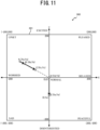
- FIG. 11 a case is considered in which 10 minutes elapses without the external stimulus acting on the robot 200 in a state in which the emotion data 121 of the robot 200 is set to the coordinates illustrated at point A (Xa, Ya).
- Ya is a positive value and, as such, the processing of step S204 is executed, and the emotion data 121 changes to a point B (Xb, Yb) that is a distance 1 separated from the point A in the direction from the point A toward the origin (0, 0).
- step S204 is executed again, and the emotion data 121 changes to a point C (Xc, Yc) that is a distance 3 separated from the point B in the direction from the point B toward the origin (0, 0).
- the pseudo-emotion of the robot 200 is changing, in a step-wise manner, to the state of the time of the first start-up.
- the Y value of the emotion data 121 changes in a step-wise manner in the negative direction. This means that the pseudo-emotion of the robot 200 is lost, and the robot 200 changes in a step-wise manner such that the appearance and actions of the robot 200 seem to become disinterested.
- the apparatus control device 100 changes, in a step-wise manner, the emotion data 121 (the emotion parameter) expressing the pseudo-emotion of the robot 200. That is, even in a case such as when the user leaves the robot 200 alone, the pseudo-emotion of the robot 200 changes and, as such, it is possible to express more lifelike emotions, and it is possible to appropriately generate the pseudo-emotion.
- the apparatus control device 100 determines that the degree of excitement (the Y value) expressed by the emotion data 121 is a positive value, that is, that the robot 200 tends to be excited (when the pseudo-emotion is close to the predetermined state)
- the apparatus control device 100 changes the emotion data 121 in the direction toward the origin on the emotion map 300, that is, changes the emotion data 121 so as to become the emotion of the time of the first start-up.
- the apparatus control device 100 determines that the degree of excitement (the Y value) expressed by the emotion data 121 is not a positive value, that is, that the robot 200 tends to be disinterested (when the pseudo-emotion is close to the predetermined state)
- the apparatus control device 100 changes the emotion data 121 in the negative direction along the Y axis of the emotion map 300, that is, changes the emotion data 121 so as to become more disinterested.
- the amount of change table 125 ( FIG. 8 ) is set such that the quantity of the emotion parameter (the emotion change amount) that is changed in a step-wise manner increases as the period (the leave-alone time) in which the external stimulus is not detected increases. Due to this, the emotion hardly changes at the initial stage of being left alone, but the emotion changes more and more as time elapses and, as such, the expression of more lifelike emotions can be realized.
- the present disclosure is not limited to the embodiment described above, and various modifications and uses are possible.
- the quantity of the emotion data that is changed in a step-wise manner is determined using the amount of change table 125 illustrated in FIG. 8 . That is, the robot 200 is controlled such that the emotion data 121 changes greater as the leave-alone time increases.
- the manner in which the emotion data 121 is changed is not limited thereto.
- the amount of change table 125 illustrated in FIG. 12A instead of that illustrated in FIG. 8 , is stored in the storage 120.
- the controller 110 acquires the emotion change amount by referencing the amount of change table 125 illustrated in FIG. 12A .
- the emotion change amount is set to increase as the amount of charge of the battery 252 increases. Due to this, it is possible to express lifelikeness such as the emotions changing in a greater manner as the energy level (the amount of charge) of the robot 200 increases.
- the quantity of the emotion data 121 is changed in a step-wise manner, is changed on the basis of the pseudo personality of the robot 200 expressed by the emotion change data 122.
- the amount of change table 125 illustrated in FIG. 12B instead of that illustrated in FIG. 8 , is stored in the storage 120.
- the controller 110 acquires the emotion change amount by referencing the amount of change table 125 illustrated in FIG. 12B .
- the personality of the robot 200 is happy, shy, active, or spoiled can be determined from the personality value radar chart 400 ( FIG. 6 ) described above.
- the emotion change amount is set greater than for other personalities. As a result, when the robot 200 is ignored and left alone, the emotions immediately change greatly, and emotion changes reflecting a spoiled personality can be realized.
- a configuration is possible in which the quantity of the emotion data 121, that is changed in a step-wise manner, is changed on the basis of whether the battery 252 of the robot 200 is being charged.
- the amount of change table 125 illustrated in FIG. 12C instead of that illustrated in FIG. 8 , is stored in the storage 120.
- the controller 110 acquires the emotion change amount by referencing the amount of change table 125 illustrated in FIG. 12C .
- a configuration is possible in which the conditions described above are combined to determine the quantity of the emotion data 121 that is changed in a step-wise manner.
- the controller 110 references the various amount of change tables 125 illustrated in FIGS. 8 , and 12A to 12C to calculate a sum value or an average value of the emotion change amounts matching the various conditions and, in step S204 or S205, the controller 110 changes the emotion data 121 a distance corresponding to the calculated value.
- the emotion data 121 when the external stimulus is not detected in the predetermined period, the emotion data 121 is changed in the direction toward the origin when the degree of excitement (the Y value) expressed by the emotion data 121 is a positive value, and is changed in the negative direction along the Y axis when the degree of excitement (the Y value) is not a positive value.
- the directions in which the emotion data 121 is changed in a step-wise manner are not limited thereto.
- a configuration is possible in which the emotion data 121 is changed in a step-wise manner in a direction in which the degree of relaxation (the X value) becomes negative.
- a configuration is possible in which the emotion data 121 is changed in a random direction every 10 minutes.
- the apparatus control device 100 is built into the robot 200, but a configuration is possible in which the apparatus control device 100 is not built into the robot 200.
- a configuration is possible in which, as illustrated in FIG. 13 , the apparatus control device 100 according to a modified example is not built into the robot 200, and is configured as a separate device (for example, a server).
- the apparatus control device 100 includes a communicator 130
- the robot 200 includes a communicator 260
- the communicator 130 and the communicator 260 are configured so as to be capable of exchanging data with each other.
- the controller 110 acquires, via the communicator 130 and the communicator 260, the external stimulus detected by the external stimulus detector 210, and controls the driver 220 and the sound outputter 230 via the communicator 130 and the communicator 260.
- the apparatus control device 100 is a control device that controls the robot 200.
- the apparatus to be controlled is not limited to the robot 200.
- the apparatus to be controlled include a wristwatch, and the like.
- impacts or the like applied to the wristwatch and detected by the acceleration sensor and the gyrosensor can be envisioned as the external stimulus.
- the emotion change data 122 and the emotion data 121 are updated in accordance with this external stimulus, and the sound effect data set in the control content table 123 is adjusted (changed) on the basis of the emotion data 121 from the point in time at which the user wears the wristwatch, and outputted.
- a configuration is possible in which, when the wristwatch is being handled roughly, a sad-like sound effect is emitted when the user puts the wristwatch on, and when the wristwatch is being handled with care, a pleased sound effect is emitted when the user is puts the wristwatch on. Furthermore, by executing the same emotion change processing in such a wristwatch, the pseudo-emotion can be changed when the user leaves the wristwatch alone and does not use the wristwatch for an extended amount of time.
- the apparatus control device 100 is not limited to a robot and can be applied to various apparatuses, and can provide the applied apparatus with pseudo-emotions, a personality, and the like. Furthermore, the apparatus control device 100 can be applied to various apparatuses to cause a user to feel as if they are pseudo-raising that apparatus.
- the action programs executed by the CPU of the controller 110 are stored in advance in the ROM or the like of the storage 120.
- the present disclosure is not limited thereto, and a configuration is possible in which the action programs for executing the various processings described above are installed on an existing general-purpose computer or the like, thereby causing that computer to function as a device corresponding to the apparatus control device 100 according to the embodiments described above.
- the programs may be stored and distributed on a non-transitory computer-readable recording medium (flexible disc, Compact Disc (CD)-ROM, Digital Versatile Disc (DVD)-ROM, Magneto Optical (MO) disc, memory card, USB memory, or the like), or may be provided by storing the programs in a storage on a network such as the internet, and causing these programs to be downloaded.
- a non-transitory computer-readable recording medium flexible disc, Compact Disc (CD)-ROM, Digital Versatile Disc (DVD)-ROM, Magneto Optical (MO) disc, memory card, USB memory, or the like
- the processings described above are realized by being divided between an operating system (OS) and an application/program, or are realized by cooperation between an OS and an application/program, it is possible to store only the portion of the application/program on the non-transitory recording medium or in the storage.
- the programs can be piggybacked on carrier waves and distributed via a network.
- the programs may be posted to a bulletin board system (BBS) on a network, and distributed via the network.
- BSS bulletin board system
- a configuration is possible in which the processings described above are executed by starting these programs and, under the control of the operating system (OS), executing the programs in the same manner as other applications/programs.
Landscapes
- Engineering & Computer Science (AREA)
- Robotics (AREA)
- Mechanical Engineering (AREA)
- Health & Medical Sciences (AREA)
- Audiology, Speech & Language Pathology (AREA)
- General Health & Medical Sciences (AREA)
- Human Computer Interaction (AREA)
- Toys (AREA)
- Manipulator (AREA)
Abstract
An apparatus control device (100) includes an emotion setter (113) that sets, in accordance with an external stimulus acting on the apparatus, an emotion parameter expressing a pseudo-emotion; and an emotion changer (115) that changes the set emotion parameter when the pseudo-emotion is close to a predetermined state and, also, the external stimulus is not detected in a predetermined period.
Description
- The present disclosure relates generally to an apparatus, an apparatus control method, and a program.
- Devices have been developed for controlling the actions of apparatuses such as robots and the like so as to make the apparatuses more similar to familiar beings such as friends or pets. Additionally, technology is known for imparting pseudo-emotions to such apparatuses. For example, Unexamined
Japanese Patent Application Publication No. 2021-069767 - In the technology described in Unexamined
Japanese Patent Application Publication No. 2021-069767 - The present disclosure is made with the view of the above situation, and an objective of the present disclosure is to appropriately generate a pseudo-emotion.
- One aspect of an apparatus according to the present disclosure is an apparatus including:
- a controller, wherein
- the controller performs processing of
- setting, in accordance with an external stimulus acting on the apparatus, an emotion parameter expressing a pseudo-emotion, and
- changing the set emotion parameter when the pseudo-emotion is close to a predetermined state and, also, the external stimulus is not detected in a predetermined period.
- According to the present disclosure, it is possible to appropriately generate a pseudo-emotion.
- A more complete understanding of this application can be obtained when the following detailed description is considered in conjunction with the following drawings, in which:
-
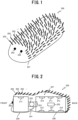
FIG. 1 is a drawing illustrating the appearance of a robot according to an embodiment; -
FIG. 2 is a cross-sectional view viewed from a side surface of the robot according to the embodiment; -
FIG. 3 is a drawing for explaining a housing of the robot according to the embodiment; -
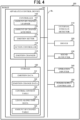
FIG. 4 is a block diagram illustrating the functional configuration of the robot according to the embodiment; -
FIG. 5 is a drawing for explaining an example of an emotion map according to the embodiment; -
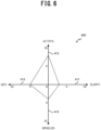
FIG. 6 is a drawing for explaining an example of a personality value radar chart according to the embodiment; -
FIG. 7 is a drawing for explaining an example of a control content table according to the embodiment; -
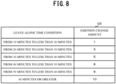
FIG. 8 is a drawing for explaining an example of an amount of change table according to the embodiment; -
FIG. 9 is a flowchart illustrating the flow of robot control processing according to the embodiment; -
FIG. 10 is a flowchart illustrating the flow of emotion change processing according to the embodiment; -
FIG. 11 is a drawing illustrating an example of emotion data changing due to the emotion change processing according to the embodiment; -
FIG. 12A is a drawing for explaining an example of an amount of change table according to a modified example; -
FIG. 12B is a drawing for explaining an example of an amount of change table according to a modified example; -
FIG. 12C is a drawing for explaining an example of an amount of change table according to a modified example; and -
FIG. 13 is a block diagram illustrating the functional configuration of an apparatus control device and a robot according to a modified example. - Hereinafter, embodiments of the present disclosure are described while referencing the drawings. Note that, in the drawings, identical or corresponding components are denoted with the same reference numerals.
- An embodiment, in which an apparatus control device according to an embodiment is applied to a
robot 200 illustrated inFIG. 1 , is described while referencing the drawings. Therobot 200 according to the embodiment is a pet robot that resembles a small animal. As illustrated inFIG. 1 , therobot 200 is covered with anexterior 201 provided withbushy fur 203 anddecorative parts 202 resembling eyes. Ahousing 207 of therobot 200 is accommodated in theexterior 201. As illustrated inFIG. 2 , thehousing 207 of therobot 200 includes ahead 204, acoupler 205, and atorso 206. Thehead 204 and thetorso 206 are coupled by thecoupler 205. - As illustrated in
FIG. 2 , thetorso 206 extends in a front-back direction. Additionally, thetorso 206 contacts, via theexterior 201, a placement surface such as a floor, a table, or the like on which therobot 200 is placed. As illustrated inFIG. 2 , atwist motor 221 is provided at a front end of thetorso 206, and thehead 204 is coupled to the front end of thetorso 206 via thecoupler 205. Thecoupler 205 is provided with avertical motor 222. Note that, inFIG. 2 , thetwist motor 221 is provided on thetorso 206, but may be provided on thecoupler 205 or on thehead 204. - The
coupler 205 couples thetorso 206 and thehead 204 so as to enable rotation (by the twist motor 221) around a first rotational axis that passes through thecoupler 205 and extends in a front-back direction of thetorso 206. Thetwist motor 221 rotates thehead 204, with respect to thetorso 206, clockwise (right rotation) within a forward rotation angle range around the first rotational axis (forward rotation), counter-clockwise (left rotation) within a reverse rotation angle range around the first rotational axis (reverse rotation), and the like. Note that, in this description, the term "clockwise" refers to clockwise when viewing the direction of thehead 204 from thetorso 206. Additionally, herein, clockwise rotation is also referred to as "twist rotation to the right", and counter-clockwise rotation is also referred to as "twist rotation to the left." A maximum value of the angle of twist rotation to the right (right rotation) or the left (left rotation) can be set as desired, and the angle of thehead 204 in a state, as illustrated inFIG. 3 , in which thehead 204 is not twisted to the right or the left is referred to as a "twist reference angle." - The
coupler 205 couples thetorso 206 and thehead 204 so as to enable rotation (by the vertical motor 222) around a second rotational axis that passes through thecoupler 205 and extends in a width direction of thetorso 206. Thevertical motor 222 rotates thehead 204 upward (forward rotation) within a forward rotation angle range around the second rotational axis, downward (reverse rotation) within a reverse rotation angle range around the second rotational axis, and the like. A maximum value of the angle of rotation upward or downward can be set as desired, and the angle of thehead 204 in a state, as illustrated inFIG. 3 , in which thehead 204 is not rotated upward or downward is referred to as a "vertical reference angle." - When the
head 204 is rotated to the vertical reference angle or upward from the vertical reference angle by vertical rotation around the second rotational axis, thehead 204 can contact, via theexterior 201, the placement surface such as the floor or the table on which therobot 200 is placed. Note that, inFIG. 2 , an example is illustrated in which the first rotational axis and the second rotational axis are orthogonal to each other, but a configuration is possible in which the first and second rotational axes are not orthogonal to each other. - As illustrated in
FIG. 2 , therobot 200 includes atouch sensor 211 on thehead 204. Thetouch sensor 211 can detect petting or striking of thehead 204 by a user. Therobot 200 also includes thetouch sensor 211 on thetorso 206. Thetouch sensor 211 can detect petting or striking of thetorso 206 by the user. - The
robot 200 includes anacceleration sensor 212 on thetorso 206. Theacceleration sensor 212 can detect an attitude (orientation) of therobot 200, and can detect being picked up, the orientation being changed, being thrown, and the like by the user. Therobot 200 includes agyrosensor 213 on thetorso 206. Thegyrosensor 213 can detect rolling, rotating, and the like of therobot 200. - The
robot 200 includes a microphone 214 on thetorso 206. Themicrophone 214 can detect external sounds. Furthermore, therobot 200 includes a speaker 215 on thetorso 206. The speaker 215 can be used to emit a sound (sound effect) of therobot 200. - The
robot 200 includes apower receiver 251 on a bottom surface of thetorso 206. Therobot 200 is driven by a rechargeable battery (cell) 252 provided in thehousing 207, and receives, by thepower receiver 251, power sent from a wireless charger to charge thebattery 252. In one example, the wireless charger resembles a pet cage (house), and includes a sheet-like power-supplying placement surface. Charging of thebattery 252 starts when therobot 200 is placed on the power-supplying placement surface of the wireless charger. - Note that, in the present embodiment, the
acceleration sensor 212, thegyrosensor 213, themicrophone 214, and the speaker 215 are provided on thetorso 206, but a configuration is possible in which all or a portion of these components are provided on thehead 204. Note that a configuration is possible in which, in addition to theacceleration sensor 212, thegyrosensor 213, themicrophone 214, and the speaker 215 provided on thetorso 206, all or a portion of these components are also provided on thehead 204. Thetouch sensor 211 is provided on each of thehead 204 and thetorso 206, but a configuration is possible in which thetouch sensor 211 is provided on only one of thehead 204 and thetorso 206. Moreover, a configuration is possible in which a plurality of any of these components is provided. - Next, the functional configuration of the
robot 200 is described. As illustrated inFIG. 4 , therobot 200 includes anapparatus control device 100, anexternal stimulus detector 210, adriver 220, asound outputter 230, anoperation inputter 240, and apower supply controller 250. Additionally, theapparatus control device 100 includes acontroller 110, and astorage 120. InFIG. 4 , theapparatus control device 100, and theexternal stimulus detector 210, thedriver 220, thesound outputter 230, theoperation inputter 240, and thepower supply controller 250 are connected to each other via a bus line BL, but this is merely an example. - A configuration is possible in which the
apparatus control device 100, and theexternal stimulus detector 210, thedriver 220, thesound outputter 230, theoperation inputter 240, and thepower supply controller 250 are connected by a wired interface such as a universal serial bus (USB) cable or the like, or by a wireless interface such as Bluetooth (registered trademark) or the like. Additionally, a configuration is possible in which thecontroller 110 and thestorage 120 are connected via the bus line BL. - The
apparatus control device 100 controls, by thecontroller 110 and thestorage 120, actions of therobot 200. - In one example, the
controller 110 is configured from a central processing unit (CPU) or the like, and executes various processings (robot control processing, emotion change processing, and the like), described later, using programs stored in thestorage 120. Note that thecontroller 110 is compatible with multithreading functionality, in which a plurality of processings are executed in parallel. As such, thecontroller 110 can execute the various processings (robot control processing, emotion change processing, and the like), described later, in parallel. Additionally, thecontroller 110 is provided with a clock function and a timer function, and can measure the date and time, and the like. - The
controller 110 includes, as a functional configuration according to the present disclosure, an amount ofchange learner 111, an amount ofchange acquirer 112, anemotion setter 113, anaction controller 114, and anemotion changer 115. - The amount of
change learner 111 learns and stores an emotion change parameter (emotion change data 122, described later) in accordance with the external stimulus detected by theexternal stimulus detector 210. The emotion change parameter is a parameter for changing the pseudo-emotion of therobot 200. Specifically, the amount ofchange learner 111 increases/decreases theemotion change data 122 in accordance with the external stimulus by robot control processing, described later. - The amount of
change acquirer 112 acquires, in accordance with the detected external stimulus, the emotion change parameter (the emotion change data 122) learned by the amount ofchange learner 111. The amount ofchange acquirer 112 is described in detail later. - The
emotion setter 113 sets, in accordance with the emotion change parameter (the emotion change data 122) acquired by the amount ofchange acquirer 112, an emotion parameter (emotion data 121, described later) expressing the pseudo-emotion of therobot 200. Theemotion setter 113 is described in detail later. - The
action controller 114 controls the actions of therobot 200 in accordance with the external stimulus detected by theexternal stimulus detector 210. Theaction controller 114 is described in detail later. - The
emotion changer 115 executes emotion change processing, described later, to change the pseudo-emotion of therobot 200 in a step-wise manner when the external stimulus acting on therobot 200 is not detected in a predetermined period. Theemotion changer 115 is described in detail later. - The
storage 120 is configured from read-only memory (ROM), flash memory, random access memory (RAM), or the like. Programs to be executed by the CPU of thecontroller 110, and data needed in advance to execute these programs are stored in the ROM. The flash memory is writable non-volatile memory, and stores data that is desired to be retained even after the power is turned OFF. Data that is created or modified during the execution of the programs is stored in the RAM. - The
external stimulus detector 210 includes thetouch sensor 211, theacceleration sensor 212, thegyrosensor 213, and themicrophone 214 described above. Thecontroller 110 acquires, as external stimulus data, detection values detected by the various sensors of theexternal stimulus detector 210. The external stimulus data expresses the external stimulus acting on therobot 200. Note that a configuration is possible in which theexternal stimulus detector 210 includes sensors other than thetouch sensor 211, theacceleration sensor 212, thegyrosensor 213, and themicrophone 214. The types of external stimuli acquirable by thecontroller 110 can be increased by increasing the types of sensors of theexternal stimulus detector 210. - The
touch sensor 211 detects contacting by some sort of object. Thetouch sensor 211 is configured from a pressure sensor or a capacitance sensor, for example. A detection value detected by thetouch sensor 211 expresses the strength of contact. Additionally, thetouch sensor 211 is capable of directional contact detection, and detects the strength of contact in three axial directions, namely contact from the front-back direction (the X-axis direction), contact from a width (left-right) direction (Y-axis direction), and contact from a vertical direction (Z-axis direction) of thetorso 206 of therobot 200. Therefore, the detection value of thetouch sensor 211 is three-dimensional data constituted by values of the strength of contact from the X-axis direction, the strength of contact from the Y-axis direction, and the strength of contact from the Z-axis direction. Thecontroller 110 can, on the basis of the detection value from thetouch sensor 211, detect that therobot 200 is being pet, is being struck, and the like by the user. - The
acceleration sensor 212 detects acceleration in three axial directions, namely the front-back direction (X-axis direction), the width (left-right) direction (Y-axis direction), and the vertical direction (Z direction) of thetorso 206 of therobot 200. Therefore, the acceleration value detected by theacceleration sensor 212 is three-dimensional data constituted by values of X-axis direction acceleration, Y-axis direction acceleration, and Z-axis direction acceleration. Theacceleration sensor 212 detects gravitational acceleration when therobot 200 is stopped and, as such, thecontroller 110 can detect a current attitude of therobot 200 on the basis of the gravitational acceleration detected by theacceleration sensor 212. Additionally, when, for example, the user picks up or throws therobot 200, theacceleration sensor 212 detects, in addition to the gravitational acceleration, acceleration caused by the movement of therobot 200. Accordingly, thecontroller 110 can detect the movement of therobot 200 by removing the gravitational acceleration component from the detection value detected by theacceleration sensor 212. - The
gyrosensor 213 detects an angular velocity from when rotation is applied to thetorso 206 of therobot 200. Specifically, thegyrosensor 213 detects the angular velocity on three axes of rotation, namely rotation around the front-back direction (the X-axis direction), rotation around the width (left-right) direction (the Y-axis direction), and rotation around the vertical direction (the Z-axis direction) of thetorso 206. Therefore, an angular velocity value detected by thegyrosensor 213 is three-dimensional data constituted by the values of X-axis rotation angular velocity, Y-axis rotation angular velocity, and Z-axis rotation angular velocity. Thecontroller 110 can more accurately detect the movement of therobot 200 by combining the detection value detected by theacceleration sensor 212 and the detection value detected by thegyrosensor 213. - Note that the
touch sensor 211, theacceleration sensor 212, and thegyrosensor 213 are synchronized, detect each of the strength of contact, the acceleration, and the angular velocity at the same timing, and output the detection values to thecontroller 110 at the same timing. Specifically, thetouch sensor 211, theacceleration sensor 212, and thegyrosensor 213 detect the strength of contact, the acceleration, and the angular velocity at the same timing every 0.25 seconds, for example. - The
microphone 214 detects ambient sound of therobot 200. Thecontroller 110 can, for example, detect, on the basis of a component of the sound detected by themicrophone 214, that the user is speaking to therobot 200, that the user is clapping their hands, and the like. - The
driver 220 includes thetwist motor 221 and thevertical motor 222. Thedriver 220 is driven by thecontroller 110. As a result, therobot 200 can express actions such as, for example, lifting thehead 204 up (rotating upward around the second rotational axis), twisting thehead 204 sideways (twisting/rotating to the right or to the left around the first rotational axis), and the like. Motion data for driving thedriver 220 in order to express these actions is recorded in a control content table 123, described later. - The
sound outputter 230 includes the speaker 215, and sound is output from the speaker 215 as a result of sound data being input into thesound outputter 230 by thecontroller 110. For example, therobot 200 emits a pseudo-animal sound as a result of thecontroller 110 inputting animal sound data of therobot 200 into thesound outputter 230. This animal sound data is also recorded as sound effect data in the control content table 123. - In one example, the
operation inputter 240 is configured from an operation button, a volume knob, or the like. Theoperation inputter 240 is an interface for receiving user operations such as, for example, turning the power ON/OFF, adjusting the volume of the output sound, and the like. - The
power supply controller 250 includes a sub-microcomputer, a charging integrated circuit (IC), a power supply control IC, thepower receiver 251, and the like, and performs charging of thebattery 252 of therobot 200, acquiring of a remaining amount of thebattery 252, and power supply controlling of therobot 200. - Next, of the data stored in the
storage 120 of theapparatus control device 100, the data unique to the present embodiment, namely, theemotion data 121, theemotion change data 122, the control content table 123, leave-alone time data 124, and an amount of change table 125 are described in order. - The
emotion data 121 is data for imparting pseudo-emotions to therobot 200, and is data (X, Y) that represents coordinates on anemotion map 300. As illustrated inFIG. 5 , theemotion map 300 is expressed by a two-dimensional coordinate system with a degree of relaxation (degree of worry) axis as an X axis, and a degree of excitement (degree of disinterest) axis as a Y axis. An origin (0, 0) on theemotion map 300 represents an emotion when normal. The phrase "emotion when normal" refers to a neutral emotion at a time of the first start-up of therobot 200 after shipping from the factory. As the value of the X coordinate (X value) on theemotion map 300 is positive and the absolute value thereof increases, emotions for which the degree of relaxation is high are expressed and, as the value of the Y coordinate (Y value) on theemotion map 300 is positive and the absolute value thereof increases, emotions for which the degree of excitement is high are expressed. Additionally, as the X value is negative and the absolute value thereof increases, emotions for which the degree of worry is high are expressed and, as the Y value is negative and the absolute value thereof increases, emotions for which the degree of disinterest is high are expressed. - The
emotion data 121 has two values, namely the X value (degree of relaxation, degree of worry) and the Y value (degree of excitement, degree of disinterest) that express a plurality (in the present embodiment, four) of mutually different pseudo-emotions, and points on theemotion map 300 represented by the X value and the Y value represent the pseudo-emotions of therobot 200. An initial value of theemotion data 121 is (0, 0). Theemotion data 121 is a parameter expressing the pseudo-emotion of therobot 200 and, as such, is also called an "emotion parameter." Note that, inFIG. 5 , theemotion map 300 is expressed as a two-dimensional coordinate system, but the number of dimensions of theemotion map 300 may be set as desired. For example, a configuration is possible in which theemotion map 300 is defined by one dimension, and one value is set as theemotion data 121. Additionally, a configuration is possible in which another axis is added and theemotion map 300 is defined by three or more dimensions, and a number of values corresponding to the number of dimensions of theemotion map 300 are set as theemotion data 121. - In the present embodiment, regarding the size of the
emotion map 300, as illustrated byframe 301 ofFIG. 5 , a maximum value of both the X value and the Y value is 200 and a minimum value is -200. The X value and the Y value of theemotion data 121 cannot be set outside of theframe 301. - Returning to
FIG. 4 , theemotion change data 122 is data that sets an amount of change that each of the X value and the Y value of theemotion data 121 is increased or decreased. In the present embodiment, asemotion change data 122 corresponding to the X of theemotion data 121, DXP that increases the X value and DXM that decreases the X value are provided and, asemotion change data 122 corresponding to the Y value of theemotion data 121, DYP that increases the Y value and DYM that decreases the Y value are provided. Specifically, theemotion change data 122 includes the following four variables. These variables are parameters that change the pseudo-emotion of therobot 200 and, as such, are also called "emotion change parameters." - DXP: Tendency to relax (tendency to change in the positive value direction of the X value on the emotion map)
- DXM: Tendency to worry (tendency to change in the negative value direction of the X value on the emotion map)
- DYP: Tendency to be excited (tendency to change in the positive value direction of the Y value on the emotion map)
- DYM: Tendency to be disinterested (tendency to change in the negative value direction of the Y value on the emotion map)
- In the present embodiment, an example is described in which the initial value of each of these variables is set to 10 and, during robot control processing, described later, the value increases to a maximum of 20 by processing for learning emotion change data. Due to this learning processing, the
emotion change data 122, that is, the degree of change of emotion changes and, as such, therobot 200 assumes various personalities in accordance with the manner in which the user interacts with therobot 200. That is, the personality of eachindividual robot 200 is formed differently on the basis of the manner in which the user interacts with therobot 200. - In the present embodiment, each piece of personality data (personality value) is derived by subtracting 10 from each piece of
emotion change data 122. Specifically, a value obtained by subtracting 10 from DXP that expresses a tendency to be relaxed is set as a personality value (happy), a value obtained by subtracting 10 from DXM that expresses a tendency to be worried is set as a personality value (shy), a value obtained by subtracting 10 from DYP that expresses a tendency to be excited is set as a personality value (active), and a value obtained by subtracting 10 from DYM that expresses a tendency to be disinterested is set as a personality value (spoiled). As a result, for example, as illustrated inFIG. 6 , it is possible to generate a personalityvalue radar chart 400 by plotting each of the personality value (happy) onaxis 411, the personality value (active) onaxis 412, the personality value (shy) onaxis 413, and the personality value (spoiled) onaxis 414. Thus, the values of the emotion change parameters (emotion change data 122) can be said to express the pseudo personality of therobot 200. - As illustrated in
FIG. 7 , control conditions and control data are associated and stored in the control content table 123. When a control condition is satisfied (for example, some sort of external stimulus is detected), thecontroller 110 controls thedriver 220 and thesound outputter 230 on the basis of the corresponding control data (motion data for expressing an action by thedriver 220, and sound effect data for outputting a sound effect from the sound outputter 230). - As illustrated in
FIG. 7 , the motion data is a series of sequence data for controlling the driver 220 (arranged as "Time (ms) : Rotational angle (degree) of vertical motor 222 : Rotational angle (degree) oftwist motor 221"). For example, when the body is petted, thecontroller 110 and thedriver 220 are controlled so that, firstly (at 0 sec), the rotational angles of thevertical motor 222 and thetwist motor 221 are set to 0 degrees (vertical reference angle and twist reference angle), at 0.5 sec, thehead 204 is raised so that the rotational angle of thevertical motor 222 becomes 60 degrees, and at 1 sec, thehead 204 is twisted so that the rotational angle of thetwist motor 221 becomes 60 degrees. - Regarding the sound effect data, to facilitate ease of understanding, text describing each piece of the sound effect data is included in
FIG. 7 , but in actuality, the sound effect data (sampled sound data) described by the text itself is stored in the control content table 123 as the sound effect data. Additionally, a value representing a desinence position is included in the sound effect data (for example, "Desinence: 30%"). This value is obtained by expressing the desinence position as a percentage from the beginning of the length of the entire sound effect data, and is used when changing a tone of a sound effect (changing the frequency of the desinence) in control data change/playback processing, described later. - Note that, in the control content table 123 illustrated in
FIG. 7 , a condition related to emotion (expressed by the coordinates on the emotion map 300) is not included in the control conditions, but a configuration is possible in which a condition related to emotion is included in the control conditions, and the control data is changed in accordance with the emotion. - Returning to
FIG. 4 , the leave-alone time data 124 is data expressing an amount of time (leave-alone time) that therobot 200 has been left alone. In the present embodiment, an amount of time that the external stimulus acting on therobot 200 is not detected is measured as the leave-alone time, and the leave-alone time is reset to 0 when the external stimulus is detected. - As illustrated in
FIG. 8 , leave-alone time conditions and emotion change amounts are associated and stored in the amount of change table 125. Here, the "emotion change amount" corresponds to a distance on theemotion map 300. When the leave-alone time of therobot 200 satisfies a leave-alone time condition, the controller 110 (the emotion changer 115) changes the emotion data in accordance with the corresponding emotion change amount. Specifically, thecontroller 110 changes, in a specific direction, the coordinates (X, Y) on theemotion map 300 expressed in the emotion data 121 a distance expressed by the corresponding emotion change amount. As illustrated inFIG. 8 , values of the amount of change table 125 are set such that the emotion change amount increases as the leave-alone time increases. - Next, the robot control processing executed by the
controller 110 of theapparatus control device 100 is described while referencing the flowchart illustrated inFIG. 9 . The robot control processing is processing in which theapparatus control device 100 controls the actions, sound, and the like of therobot 200 on the basis of the detection values from theexternal stimulus detector 210 or the like. The robot control processing starts when the user turns ON the power of therobot 200. - Firstly, the
controller 110 initializes the various types of data such as theemotion data 121, theemotion change data 122, and the like (step S101). Note that, a configuration is possible in which, for the second and subsequent startups of therobot 200, the various values from when the power of therobot 200 was last turned OFF are set in step S101. This can be realized by thecontroller 110 storing the various data values in nonvolatile memory (flash memory or the like) of thestorage 120 when an operation for turning the power OFF is performed the last time and, when the power is thereafter turned ON, setting the stored values as the various data values. - Then, the
controller 110 starts measuring the leave-alone time using the clock function (step S102). The leave-alone time is continuously measured until the leave-alone time is reset by step S109, described later. - Next, the
controller 110 acquires the detection value detected by the external stimulus detector 210 (step S103). Then, thecontroller 110 determines, on the basis of the acquired detection value, whether there is an external stimulus (step S104). - When there is an external stimulus (step S104; Yes), the controller 110 (the amount of change acquirer 112) acquires the
emotion change data 122 in accordance with the detection value of the external stimulus acquired in step S103 (step S 105). Specifically, when, for example, petting of thehead 204 is detected by thetouch sensor 211 of thehead 204 as the external stimulus, therobot 200 obtains a pseudo sense of relaxation and, as such, thecontroller 110 acquires DXP as theemotion change data 122 to be added to the X value of theemotion data 121. - Then, the controller 110 (the emotion setter 113) sets the
emotion data 121 in accordance with theemotion change data 122 acquired in step S105 (step S106). Specifically, when, for example, DXP is acquired as theemotion change data 122 in step S104, thecontroller 110 adds the DXP of theemotion change data 122 to the X value of theemotion data 121. - In steps S105 and S106, any type of settings are possible for the type of
emotion change data 122 acquired and theemotion data 121 set for each individual external stimulus. Examples are described below. - The
head 204 is petted (relax): X = X+DXP - The
head 204 is struck (worry): X = X-DXM - (these external stimuli can be detected by the
touch sensor 211 of the head 204) - The
torso 206 is petted (excite): Y = Y+DYP - The
torso 206 is struck (disinterest): Y = Y-DYM - (these external stimuli can be detected by the
touch sensor 211 of the torso 206) - Held with head upward (pleased): X = X+DXP, and Y = Y+DYP
- Suspended with head downward (sad): X = X-DXM, and Y = Y-DYM
- (these external stimuli can be detected by the
touch sensor 211, theacceleration sensor 212, and the gyrosensor 213) - Spoken to in kind voice (peaceful): X = X+DXP, and Y = Y-DYM
- Yelled out in loud voice (upset): X = X-DXM, and Y = Y+DYP
- (these external stimuli can be detected by the microphone 214)
- However, in a case in which a value (X value, Y value) of the
emotion data 121 exceeds the maximum value of theemotion map 300 when adding theemotion change data 122, that value of theemotion data 121 is set to the maximum value of theemotion map 300. In addition, in a case in which a value of theemotion data 121 is less than the minimum value of theemotion map 300 when subtracting theemotion change data 122, that value of theemotion data 121 is set to the minimum value of theemotion map 300. - Next, the controller 110 (the action controller 114) references the control content table 123 and acquires the control data corresponding to the control condition that is satisfied by the acquired detection value of the external stimulus (step S107).
- Then, the controller 110 (the action controller 114) plays back the control data acquired in step S107 (step S108). Note that a configuration is possible in which the
controller 110 adjusts (changes), on the basis of theemotion data 121, the content of the control data to be played back. - Next, the
controller 110 resets the leave-alone time to 0 (step S109), and starts measuring the leave-alone time (step S110). Then, thecontroller 110 executes step S113. - Meanwhile, when there is not an external stimulus in step S104 (step S104; No), the
controller 110 determines whether to perform a spontaneous action (a breathing imitation action that is an action resembling breathing of a creature, or the like) (step S111). Any method may be used as the method for determining whether to perform the spontaneous action but, in the present embodiment, it is assumed that the determination of step S111 is "Yes" and the breathing imitation action is performed every breathing cycle (for example, two seconds). - When not performing the spontaneous action (step S111; No), the
controller 110 executes step S113. When performing the spontaneous action (step S111; Yes), thecontroller 110 executes a spontaneous action (for example, a breathing action) as the spontaneous action (step S112), and executes step S113. - The control data of this spontaneous action also is stored in the control content table 123 (such as illustrated in, for example, "breathing cycle elapsed" of the "control conditions" of
FIG. 7 ). Note that a configuration is possible in which the control content of the spontaneous action is adjusted (changed) on the basis of theemotion data 121. - In step S113, the
controller 110 uses the clock function to determine whether a date has changed. When the date has not changed (step S113; No), thecontroller 110 executes step S103. - When the date has changed (step S113; Yes), the controller 110 (the amount of change learner 111) performs learning of the emotion change data 122 (step S114), and executes step S103. The learning of the
emotion change data 122 is, specifically, processing for updating theemotion change data 122 by adding 1 to the DXP of theemotion change data 122 when the X value of theemotion data 121 is set to the maximum value of theemotion map 300 even once in step S106 of that day, adding 1 to the DYP of theemotion change data 122 when the Y value of theemotion data 121 is set to the maximum value of theemotion map 300 even once in step S106 of that day, adding 1 to the DXM of theemotion change data 122 when the X value of theemotion data 121 is set to the minimum value of theemotion map 300 even once in step S106 of that day, and adding 1 to the DYM of theemotion change data 122 when the Y value of theemotion data 121 is set to the minimum value of theemotion map 300 even once in step S106 of that day. - However, when the various values of the
emotion change data 122 become exceedingly large, the amount of change of one time of theemotion data 121 becomes exceedingly large and, as such, the maximum value of the various values of theemotion change data 122 is set to 20, for example, and the various values are limited to that maximum value or less. Here, 1 is added to each piece of theemotion change data 122, but the value to be added is not limited to 1. For example, a configuration is possible in which a number of times at which the various values of theemotion data 121 are set to the maximum value or the minimum value of theemotion map 300 is counted and, when that number of times is great, the numerical value to be added to theemotion change data 122 is increased. - Next, emotion change processing executed by the controller 110 (the emotion changer 115) of the
apparatus control device 100 is described while referencing the flowchart illustrated inFIG. 10 . The emotion change processing is processing that, while the power of therobot 200 is turned ON, is executed in parallel in a separate thread with the robot control processing described above. As a result of the emotion change processing, the emotion data set in step S106 of the robot control processing changes automatically in accordance with the leave-alone time. - Firstly, the
controller 110 references the leave-alone time data 124 and determines whether the current leave-alone time is 10 minutes or greater (step S201). When the leave-alone time is less than 10 minutes (step S201; No), thecontroller 110 stands-by without executing the subsequent steps. - When the leave-alone time is 10 minutes or greater (step S201; Yes), the
controller 110 references the amount of change table 125 illustrated inFIG. 8 , and acquires the emotion change amount corresponding to the leave-alone time condition satisfied by the current leave-alone time (step S202). For example, when the leave-alone time is 10 minutes, "1" is acquired as the emotion change amount. - Returning to
FIG. 10 , next, thecontroller 110 determines whether the Y coordinate value (Y value) on theemotion map 300 expressed by theemotion data 121 is positive (greater than 0) (step S203). The determination of step S203 corresponds to determining whether therobot 200 is in an excited state. - When the Y value of the
emotion data 121 is a positive value (step S203; Yes), that is, when therobot 200 is in an excited state, thecontroller 110 changes the values (X, Y) on theemotion map 300 expressed by theemotion data 121 in a direction toward the origin (0, 0) a distance corresponding to the emotion change amount acquired in step S202 (step S204), and executes step S206. As a result of this processing, the pseudo-emotion of therobot 200 that is in the excited state changes so as to become a neutral emotion, and therobot 200 appears to be in a calm state. - Meanwhile, when the Y value of the
emotion data 121 is not a positive value (step S203; No), thecontroller 110 changes the values (X, Y) on theemotion map 300 in a direction (negative direction) in which that Y value decreases a distance corresponding to the emotion change amount acquired in step S202 (step S205), and executes step S206. As a result of this processing, the pseudo-emotion of therobot 200 changes so as to become disinterested, and therobot 200 appears to be in a calm state. - In step S206, the
controller 110 stands-by for 10 minutes. Then, thecontroller 110 executes step S201. - Next, examples of the change in the
emotion data 121 resulting from the emotion change processing described above are described. For example, as illustrated inFIG. 11 , a case is considered in which 10 minutes elapses without the external stimulus acting on therobot 200 in a state in which theemotion data 121 of therobot 200 is set to the coordinates illustrated at point A (Xa, Ya). In this case, Ya is a positive value and, as such, the processing of step S204 is executed, and theemotion data 121 changes to a point B (Xb, Yb) that is adistance 1 separated from the point A in the direction from the point A toward the origin (0, 0). - Then, when left alone for another 10 minutes (when left alone for a total of 20 minutes), Yb is a positive value and, as such, the processing of step S204 is executed again, and the
emotion data 121 changes to a point C (Xc, Yc) that is adistance 3 separated from the point B in the direction from the point B toward the origin (0, 0). This means that the pseudo-emotion of therobot 200 is changing, in a step-wise manner, to the state of the time of the first start-up. - Thereafter, every
time 10 minutes of the leave-alone time elapses, theemotion data 121 for which the Y value is positive changes in the direction of the origin, and theemotion data 121 changes until reaching the point D (Xd = 0, Yd = 0). Then, when therobot 200 is left alone in this state for another 10 minutes, Yd is not a positive value and, as such, the processing of step S205 is executed, and theemotion data 121 changes from the point D to the point E (Xe = 0, Ye) in the negative direction along the Y axis. Then, everytime 10 minutes elapses without the external stimulus being detected, the Y value of theemotion data 121 changes in a step-wise manner in the negative direction. This means that the pseudo-emotion of therobot 200 is lost, and therobot 200 changes in a step-wise manner such that the appearance and actions of therobot 200 seem to become disinterested. - As described above, when the external stimulus is not detected in the predetermined period, the
apparatus control device 100 according to the present embodiment changes, in a step-wise manner, the emotion data 121 (the emotion parameter) expressing the pseudo-emotion of therobot 200. That is, even in a case such as when the user leaves therobot 200 alone, the pseudo-emotion of therobot 200 changes and, as such, it is possible to express more lifelike emotions, and it is possible to appropriately generate the pseudo-emotion. - Additionally, when the
apparatus control device 100 according to the present embodiment determines that the degree of excitement (the Y value) expressed by theemotion data 121 is a positive value, that is, that therobot 200 tends to be excited (when the pseudo-emotion is close to the predetermined state), theapparatus control device 100 changes theemotion data 121 in the direction toward the origin on theemotion map 300, that is, changes theemotion data 121 so as to become the emotion of the time of the first start-up. Moreover, when theapparatus control device 100 according to the present embodiment determines that the degree of excitement (the Y value) expressed by theemotion data 121 is not a positive value, that is, that therobot 200 tends to be disinterested (when the pseudo-emotion is close to the predetermined state), theapparatus control device 100 changes theemotion data 121 in the negative direction along the Y axis of theemotion map 300, that is, changes theemotion data 121 so as to become more disinterested. By changing in this manner, it is possible to provide arobot 200 that becomes calm and gradually more and more composed as a result of being left alone, that can express emotion such as becoming disinterested, and that demonstrates emotions similar to a real creature or pet. - With the
apparatus control device 100 according to the present embodiment, the amount of change table 125 (FIG. 8 ) is set such that the quantity of the emotion parameter (the emotion change amount) that is changed in a step-wise manner increases as the period (the leave-alone time) in which the external stimulus is not detected increases. Due to this, the emotion hardly changes at the initial stage of being left alone, but the emotion changes more and more as time elapses and, as such, the expression of more lifelike emotions can be realized. - The present disclosure is not limited to the embodiment described above, and various modifications and uses are possible. For example, in the embodiment described above, the quantity of the emotion data that is changed in a step-wise manner is determined using the amount of change table 125 illustrated in
FIG. 8 . That is, therobot 200 is controlled such that theemotion data 121 changes greater as the leave-alone time increases. However, the manner in which theemotion data 121 is changed is not limited thereto. - For example, a configuration is possible in which the quantity of the
emotion data 121 that is changed in a step-wise manner is changed on the basis of an amount of charge of thebattery 252 of therobot 200. In such a case, the amount of change table 125 illustrated inFIG. 12A , instead of that illustrated inFIG. 8 , is stored in thestorage 120. Moreover, in step S202 of the emotion change processing, it is sufficient that thecontroller 110 acquires the emotion change amount by referencing the amount of change table 125 illustrated inFIG. 12A . In the amount of change table 125 illustrated inFIG. 12A , the emotion change amount is set to increase as the amount of charge of thebattery 252 increases. Due to this, it is possible to express lifelikeness such as the emotions changing in a greater manner as the energy level (the amount of charge) of therobot 200 increases. - For example, a configuration is possible in which the quantity of the
emotion data 121, that is changed in a step-wise manner, is changed on the basis of the pseudo personality of therobot 200 expressed by theemotion change data 122. In such a case, for example, the amount of change table 125 illustrated inFIG. 12B , instead of that illustrated inFIG. 8 , is stored in thestorage 120. Moreover, in step S202 of the emotion change processing, it is sufficient that thecontroller 110 acquires the emotion change amount by referencing the amount of change table 125 illustrated inFIG. 12B . Note that whether the personality of therobot 200 is happy, shy, active, or spoiled can be determined from the personality value radar chart 400 (FIG. 6 ) described above. In the amount of change table 125 illustrated inFIG. 12B , in the case of a spoiled personality, the emotion change amount is set greater than for other personalities. As a result, when therobot 200 is ignored and left alone, the emotions immediately change greatly, and emotion changes reflecting a spoiled personality can be realized. - For example, a configuration is possible in which the quantity of the
emotion data 121, that is changed in a step-wise manner, is changed on the basis of whether thebattery 252 of therobot 200 is being charged. In such a case, for example, the amount of change table 125 illustrated inFIG. 12C , instead of that illustrated inFIG. 8 , is stored in thestorage 120. Moreover, in step S202 of the emotion change processing, it is sufficient that thecontroller 110 acquires the emotion change amount by referencing the amount of change table 125 illustrated inFIG. 12C . - Note that a configuration is possible in which the conditions described above are combined to determine the quantity of the
emotion data 121 that is changed in a step-wise manner. For example, a configuration is possible in which, in step S202 of the emotion change processing, thecontroller 110 references the various amount of change tables 125 illustrated inFIGS. 8 , and12A to 12C to calculate a sum value or an average value of the emotion change amounts matching the various conditions and, in step S204 or S205, thecontroller 110 changes the emotion data 121 a distance corresponding to the calculated value. - In the embodiment described above, when the external stimulus is not detected in the predetermined period, the
emotion data 121 is changed in the direction toward the origin when the degree of excitement (the Y value) expressed by theemotion data 121 is a positive value, and is changed in the negative direction along the Y axis when the degree of excitement (the Y value) is not a positive value. However, the directions in which theemotion data 121 is changed in a step-wise manner are not limited thereto. For example, a configuration is possible in which theemotion data 121 is changed in a step-wise manner in a direction in which the degree of relaxation (the X value) becomes negative. Additionally, a configuration is possible in which theemotion data 121 is changed in a random direction every 10 minutes. - In the embodiments described above, a configuration is described in which the
apparatus control device 100 is built into therobot 200, but a configuration is possible in which theapparatus control device 100 is not built into therobot 200. For example, a configuration is possible in which, as illustrated inFIG. 13 , theapparatus control device 100 according to a modified example is not built into therobot 200, and is configured as a separate device (for example, a server). In this modified example, theapparatus control device 100 includes acommunicator 130, therobot 200 includes acommunicator 260, and thecommunicator 130 and thecommunicator 260 are configured so as to be capable of exchanging data with each other. Moreover, thecontroller 110 acquires, via thecommunicator 130 and thecommunicator 260, the external stimulus detected by theexternal stimulus detector 210, and controls thedriver 220 and thesound outputter 230 via thecommunicator 130 and thecommunicator 260. - In the embodiments described above, the
apparatus control device 100 is a control device that controls therobot 200. However, the apparatus to be controlled is not limited to therobot 200. Examples of the apparatus to be controlled include a wristwatch, and the like. For example, in the case of an apparatus that controls a wristwatch that is capable of outputting sound and that includes an acceleration sensor and a gyrosensor, impacts or the like applied to the wristwatch and detected by the acceleration sensor and the gyrosensor can be envisioned as the external stimulus. Additionally, it is expected that theemotion change data 122 and theemotion data 121 are updated in accordance with this external stimulus, and the sound effect data set in the control content table 123 is adjusted (changed) on the basis of theemotion data 121 from the point in time at which the user wears the wristwatch, and outputted. - Accordingly, a configuration is possible in which, when the wristwatch is being handled roughly, a sad-like sound effect is emitted when the user puts the wristwatch on, and when the wristwatch is being handled with care, a pleased sound effect is emitted when the user is puts the wristwatch on. Furthermore, by executing the same emotion change processing in such a wristwatch, the pseudo-emotion can be changed when the user leaves the wristwatch alone and does not use the wristwatch for an extended amount of time.
- Thus, the
apparatus control device 100 is not limited to a robot and can be applied to various apparatuses, and can provide the applied apparatus with pseudo-emotions, a personality, and the like. Furthermore, theapparatus control device 100 can be applied to various apparatuses to cause a user to feel as if they are pseudo-raising that apparatus. - In the embodiments described above, a description is given in which the action programs executed by the CPU of the
controller 110 are stored in advance in the ROM or the like of thestorage 120. However, the present disclosure is not limited thereto, and a configuration is possible in which the action programs for executing the various processings described above are installed on an existing general-purpose computer or the like, thereby causing that computer to function as a device corresponding to theapparatus control device 100 according to the embodiments described above. - Any method can be used to provide such programs. For example, the programs may be stored and distributed on a non-transitory computer-readable recording medium (flexible disc, Compact Disc (CD)-ROM, Digital Versatile Disc (DVD)-ROM, Magneto Optical (MO) disc, memory card, USB memory, or the like), or may be provided by storing the programs in a storage on a network such as the internet, and causing these programs to be downloaded.
- Additionally, in cases in which the processings described above are realized by being divided between an operating system (OS) and an application/program, or are realized by cooperation between an OS and an application/program, it is possible to store only the portion of the application/program on the non-transitory recording medium or in the storage. Additionally, the programs can be piggybacked on carrier waves and distributed via a network. For example, the programs may be posted to a bulletin board system (BBS) on a network, and distributed via the network. Moreover, a configuration is possible in which the processings described above are executed by starting these programs and, under the control of the operating system (OS), executing the programs in the same manner as other applications/programs.
- The foregoing describes some example embodiments for explanatory purposes. Although the foregoing discussion has presented specific embodiments, persons skilled in the art will recognize that changes may be made in form and detail without departing from the broader spirit and scope of the invention. Accordingly, the specification and drawings are to be regarded in an illustrative rather than a restrictive sense. This detailed description, therefore, is not to be taken in a limiting sense, and the scope of the invention is defined only by the included claims, along with the full range of equivalents to which such claims are entitled.
Claims (15)
- An apparatus comprising:a controller (110), whereinthe controller (110) performs processing ofsetting, in accordance with an external stimulus acting on the apparatus, an emotion parameter expressing a pseudo-emotion, andchanging the set emotion parameter when the pseudo-emotion is close to a predetermined state and, also, the external stimulus is not detected in a predetermined period.
- The apparatus according to claim 1, wherein
the controller (110) changes the emotion parameter so that the apparatus appears to be in a calm state when the pseudo-emotion is close to the predetermined state and, also, the external stimulus is not detected in the predetermined period. - The apparatus according to claim 2, wherein
the controller (110) changes the emotion parameter in a step-wise manner so that the apparatus appears to be in the calm state due to the pseudo-emotion becoming a neutral emotion when the pseudo-emotion is close to the predetermined state and, also, the external stimulus is not detected in the predetermined period. - The apparatus according to any one of claims 1 to 3, wherein
the controller (110) changes a quantity of the emotion parameter that is changed based on a period in which the external stimulus is not detected. - The apparatus according to any one of claims 1 to 3, wherein
the controller (110) changes a quantity of the emotion parameter that is changed based on a pseudo personality of the apparatus. - The apparatus according to any one of claims 1 to 3, further comprising:a battery, whereinthe controller (110) changes an amount of change of the emotion parameter in accordance with an amount of charge of the battery (252).
- The apparatus according to any one of claims 1 to 3, further comprising:a battery (252), whereinthe controller (110) changes an amount of change of the emotion parameter based on whether charging of the battery (252) is being performed.
- An apparatus control method to be executed by a controller (110) of an apparatus, the method comprising:setting, in accordance with an external stimulus acting on the apparatus, an emotion parameter expressing a pseudo-emotion; andcontrolling so as to change the set emotion parameter when the pseudo-emotion is close to a predetermined state and, also, the external stimulus is not detected in a predetermined period.
- The apparatus control method according to claim 8, wherein the controlling includes
changing the emotion parameter so that the apparatus appears to be in a calm state when the pseudo-emotion is close to the predetermined state and, also, the external stimulus is not detected in the predetermined period. - The apparatus control method according to claim 9, wherein the controlling includes
changing the emotion parameter in a step-wise manner so that the apparatus appears to be in the calm state due to the pseudo-emotion becoming a neutral emotion when the pseudo-emotion is close to the predetermined state and, also, the external stimulus is not detected in the predetermined period. - The apparatus control method according to any one of claims 8 to 10, wherein the controlling includes
changing a quantity of the emotion parameter that is changed based on a period in which the external stimulus is not detected. - The apparatus control method according to any one of claims 8 to 10, wherein the controlling includes
changing a quantity of the emotion parameter that is changed based on a pseudo personality of the apparatus. - The apparatus control method according to any one of claims 8 to 10, whereinthe apparatus further includes a battery (252), andthe controlling includes changing an amount of change of the emotion parameter in accordance with an amount of charge of the battery (252).
- The apparatus control method according to any one of claims 8 to 10, whereinthe apparatus further includes a battery (252), andthe controlling includes changing an amount of change of the emotion parameter based on whether charging of the battery (252) is being performed.
- A program readable by a computer of an apparatus, the program causing the computer to:set, in accordance with an external stimulus acting on the apparatus, an emotion parameter expressing a pseudo-emotion; andchange the set emotion parameter when the pseudo-emotion is close to a predetermined state and, also, the external stimulus is not detected in a predetermined period.
Applications Claiming Priority (1)
| Application Number | Priority Date | Filing Date | Title |
|---|---|---|---|
| JP2022154437A JP7677299B2 (en) | 2022-09-28 | 2022-09-28 | Device control device, device control method, and program |
Publications (1)
| Publication Number | Publication Date |
|---|---|
| EP4344835A1 true EP4344835A1 (en) | 2024-04-03 |
Family
ID=88098412
Family Applications (1)
| Application Number | Title | Priority Date | Filing Date |
|---|---|---|---|
| EP23198260.4A Pending EP4344835A1 (en) | 2022-09-28 | 2023-09-19 | Apparatus, apparatus control method, and program |
Country Status (3)
| Country | Link |
|---|---|
| US (1) | US20240100706A1 (en) |
| EP (1) | EP4344835A1 (en) |
| JP (2) | JP7677299B2 (en) |
Citations (9)
| Publication number | Priority date | Publication date | Assignee | Title |
|---|---|---|---|---|
| EP1112821A1 (en) * | 1999-05-10 | 2001-07-04 | Sony Corporation | Toboy device and method for controlling the same |
| US20070270074A1 (en) * | 2005-01-18 | 2007-11-22 | Aochi Yuichi | Robot Toy |
| US20190279070A1 (en) * | 2016-11-24 | 2019-09-12 | Groove X, Inc. | Autonomously acting robot that changes pupil |
| KR102051217B1 (en) * | 2018-05-29 | 2019-12-02 | 연세대학교 산학협력단 | Apparatus and method for controlling emotional expression of biomimetics robot |
| US20210089172A1 (en) * | 2019-09-23 | 2021-03-25 | Lg Electronics Inc. | Robot |
| JP2021069767A (en) | 2019-10-31 | 2021-05-06 | カシオ計算機株式会社 | Control device of apparatus, control method of apparatus and program |
| US20210402589A1 (en) * | 2019-06-17 | 2021-12-30 | Lg Electronics Inc. | Artificial intelligence (ai) robot and control method thereof |
| US20220297307A1 (en) * | 2021-03-16 | 2022-09-22 | Casio Computer Co., Ltd. | Device control apparatus, device control method, and recording medium |
| US20240246242A1 (en) * | 2023-01-25 | 2024-07-25 | Casio Computer Co., Ltd. | Robot, robot control method, and recording medium |
Family Cites Families (5)
| Publication number | Priority date | Publication date | Assignee | Title |
|---|---|---|---|---|
| US6337552B1 (en) * | 1999-01-20 | 2002-01-08 | Sony Corporation | Robot apparatus |
| JP2001162058A (en) * | 1999-12-10 | 2001-06-19 | Iesato Sato | Autonomous mobile therapeutic apparatus |
| DE112018005034B4 (en) * | 2017-09-11 | 2022-05-12 | Groove X, Inc. | Autonomously acting robot that looks at the companion |
| JP7152908B2 (en) * | 2018-09-05 | 2022-10-13 | 日本放送協会 | Gesture control device and gesture control program |
| JP6904621B1 (en) * | 2020-10-27 | 2021-07-21 | 有限会社小山直樹一級建築士事務所 | Robot control system, personality information management server and robot |
-
2022
- 2022-09-28 JP JP2022154437A patent/JP7677299B2/en active Active
-
2023
- 2023-09-06 US US18/242,534 patent/US20240100706A1/en active Pending
- 2023-09-19 EP EP23198260.4A patent/EP4344835A1/en active Pending
-
2025
- 2025-03-03 JP JP2025032973A patent/JP2025074246A/en active Pending
Patent Citations (9)
| Publication number | Priority date | Publication date | Assignee | Title |
|---|---|---|---|---|
| EP1112821A1 (en) * | 1999-05-10 | 2001-07-04 | Sony Corporation | Toboy device and method for controlling the same |
| US20070270074A1 (en) * | 2005-01-18 | 2007-11-22 | Aochi Yuichi | Robot Toy |
| US20190279070A1 (en) * | 2016-11-24 | 2019-09-12 | Groove X, Inc. | Autonomously acting robot that changes pupil |
| KR102051217B1 (en) * | 2018-05-29 | 2019-12-02 | 연세대학교 산학협력단 | Apparatus and method for controlling emotional expression of biomimetics robot |
| US20210402589A1 (en) * | 2019-06-17 | 2021-12-30 | Lg Electronics Inc. | Artificial intelligence (ai) robot and control method thereof |
| US20210089172A1 (en) * | 2019-09-23 | 2021-03-25 | Lg Electronics Inc. | Robot |
| JP2021069767A (en) | 2019-10-31 | 2021-05-06 | カシオ計算機株式会社 | Control device of apparatus, control method of apparatus and program |
| US20220297307A1 (en) * | 2021-03-16 | 2022-09-22 | Casio Computer Co., Ltd. | Device control apparatus, device control method, and recording medium |
| US20240246242A1 (en) * | 2023-01-25 | 2024-07-25 | Casio Computer Co., Ltd. | Robot, robot control method, and recording medium |
Also Published As
| Publication number | Publication date |
|---|---|
| JP7677299B2 (en) | 2025-05-15 |
| US20240100706A1 (en) | 2024-03-28 |
| JP2025074246A (en) | 2025-05-13 |
| JP2024048495A (en) | 2024-04-09 |
Similar Documents
| Publication | Publication Date | Title |
|---|---|---|
| JP7528981B2 (en) | Device control device, device, device control method and program | |
| US12343650B2 (en) | Robot, robot control method, and storage medium | |
| JP7726242B2 (en) | Robot control device, robot control method and program | |
| US20260124765A1 (en) | Robot, robot control method and recording medium | |
| JP2021069767A (en) | Control device of apparatus, control method of apparatus and program | |
| US20240100699A1 (en) | Apparatus, apparatus control method and recording medium | |
| US20240100706A1 (en) | Apparatus, apparatus control method, and recording medium | |
| JP2025129338A (en) | Robot, robot control method and program | |
| US12558792B2 (en) | Robot, robot control method and recording medium | |
| US12533817B2 (en) | Robot, robot control method and recording medium | |
| US20250100128A1 (en) | Robot, control method, and recording medium | |
| US12463443B2 (en) | Control device, control method, and non-transitory recording medium | |
| EP4342558B1 (en) | Apparatus, control method for apparatus, and program | |
| JP7643431B2 (en) | Device control device, device control method, and program | |
| US20240173636A1 (en) | Action control device, action control method, and recording medium | |
| US20240190000A1 (en) | Action control device, action control method, and recording medium | |
| US20240231373A1 (en) | Action control device, action control method, and recording medium | |
| US20250099865A1 (en) | Robot, robot control method and recording medium | |
| US20250104674A1 (en) | Performance information acquisition device, performance information acquisition method, and recording medium | |
| JP2026023899A (en) | Robot, learning data collection device, learning data collection method and program |
Legal Events
| Date | Code | Title | Description |
|---|---|---|---|
| PUAI | Public reference made under article 153(3) epc to a published international application that has entered the european phase |
Free format text: ORIGINAL CODE: 0009012 |
|
| STAA | Information on the status of an ep patent application or granted ep patent |
Free format text: STATUS: REQUEST FOR EXAMINATION WAS MADE |
|
| 17P | Request for examination filed |
Effective date: 20230919 |
|
| AK | Designated contracting states |
Kind code of ref document: A1 Designated state(s): AL AT BE BG CH CY CZ DE DK EE ES FI FR GB GR HR HU IE IS IT LI LT LU LV MC ME MK MT NL NO PL PT RO RS SE SI SK SM TR |
|
| STAA | Information on the status of an ep patent application or granted ep patent |
Free format text: STATUS: EXAMINATION IS IN PROGRESS |
|
| 17Q | First examination report despatched |
Effective date: 20250205 |