EP4344644A1 - Computer-implemented method for providing a first x-ray image and a second x-ray image acquired by an x-ray imaging system - Google Patents
Computer-implemented method for providing a first x-ray image and a second x-ray image acquired by an x-ray imaging system Download PDFInfo
- Publication number
- EP4344644A1 EP4344644A1 EP22198710.0A EP22198710A EP4344644A1 EP 4344644 A1 EP4344644 A1 EP 4344644A1 EP 22198710 A EP22198710 A EP 22198710A EP 4344644 A1 EP4344644 A1 EP 4344644A1
- Authority
- EP
- European Patent Office
- Prior art keywords
- ray
- image
- ray image
- imaging system
- impression
- Prior art date
- Legal status (The legal status is an assumption and is not a legal conclusion. Google has not performed a legal analysis and makes no representation as to the accuracy of the status listed.)
- Pending
Links
Images



Classifications
-
- A—HUMAN NECESSITIES
- A61—MEDICAL OR VETERINARY SCIENCE; HYGIENE
- A61B—DIAGNOSIS; SURGERY; IDENTIFICATION
- A61B6/00—Apparatus or devices for radiation diagnosis; Apparatus or devices for radiation diagnosis combined with radiation therapy equipment
- A61B6/50—Apparatus or devices for radiation diagnosis; Apparatus or devices for radiation diagnosis combined with radiation therapy equipment specially adapted for specific body parts; specially adapted for specific clinical applications
- A61B6/502—Apparatus or devices for radiation diagnosis; Apparatus or devices for radiation diagnosis combined with radiation therapy equipment specially adapted for specific body parts; specially adapted for specific clinical applications for diagnosis of breast, i.e. mammography
-
- A—HUMAN NECESSITIES
- A61—MEDICAL OR VETERINARY SCIENCE; HYGIENE
- A61B—DIAGNOSIS; SURGERY; IDENTIFICATION
- A61B6/00—Apparatus or devices for radiation diagnosis; Apparatus or devices for radiation diagnosis combined with radiation therapy equipment
- A61B6/02—Arrangements for diagnosis sequentially in different planes; Stereoscopic radiation diagnosis
- A61B6/025—Tomosynthesis
-
- A—HUMAN NECESSITIES
- A61—MEDICAL OR VETERINARY SCIENCE; HYGIENE
- A61B—DIAGNOSIS; SURGERY; IDENTIFICATION
- A61B6/00—Apparatus or devices for radiation diagnosis; Apparatus or devices for radiation diagnosis combined with radiation therapy equipment
- A61B6/46—Arrangements for interfacing with the operator or the patient
- A61B6/461—Displaying means of special interest
- A61B6/463—Displaying means of special interest characterised by displaying multiple images or images and diagnostic data on one display
-
- A—HUMAN NECESSITIES
- A61—MEDICAL OR VETERINARY SCIENCE; HYGIENE
- A61B—DIAGNOSIS; SURGERY; IDENTIFICATION
- A61B6/00—Apparatus or devices for radiation diagnosis; Apparatus or devices for radiation diagnosis combined with radiation therapy equipment
- A61B6/52—Devices using data or image processing specially adapted for radiation diagnosis
- A61B6/5211—Devices using data or image processing specially adapted for radiation diagnosis involving processing of medical diagnostic data
-
- G—PHYSICS
- G06—COMPUTING OR CALCULATING; COUNTING
- G06T—IMAGE DATA PROCESSING OR GENERATION, IN GENERAL
- G06T12/00—Tomographic reconstruction from projections
- G06T12/10—Image preprocessing, e.g. calibration, positioning of sources or scatter correction
-
- G—PHYSICS
- G06—COMPUTING OR CALCULATING; COUNTING
- G06T—IMAGE DATA PROCESSING OR GENERATION, IN GENERAL
- G06T2211/00—Image generation
- G06T2211/40—Computed tomography
- G06T2211/436—Limited angle
-
- G—PHYSICS
- G06—COMPUTING OR CALCULATING; COUNTING
- G06T—IMAGE DATA PROCESSING OR GENERATION, IN GENERAL
- G06T2211/00—Image generation
- G06T2211/40—Computed tomography
- G06T2211/441—AI-based methods, deep learning or artificial neural networks
Definitions
- the invention relates to a computer-implemented method for providing a first X-ray image and a second X-ray image acquired by an X-ray imaging system, an X-ray imaging system, a computer program product, and a computer-readable medium, wherein an X-ray image can be provided with different image impressions to the user.
- An X-ray imaging system e.g. a radiography system or a fluoroscopy system, comprises an X-ray source and an X-ray detector.
- the examination object in particular a patient, is arranged between the X-ray source and the X-ray detector so that an X-ray image of an examination region can be acquired.
- a mammography system includes an X-ray source and an X-ray detector, with a breast arranged between the X-ray source and the X-ray detector.
- the examination area comprises the breast, especially the entire breast.
- the breast is compressed or fixed by means of a compression unit.
- the surface of the X-ray detector or a housing of the X-ray detector and an essentially parallel arranged compression plate can be used.
- other forms of the compression unit are known.
- An X-ray data set can be generated.
- the X-ray data set may include a digital full-field mammography image and / or a tomosynthesis image.
- Modern mammography systems offer a tomosynthesis function to generate a series of projections that allow a three-dimensional representation of the breast using reconstructed layers.
- the X-ray emitter or the X-ray source moves in an angular range of 15 to 50 degrees over the compressed breast.
- the digital full-field mammography image and the tomosynthesis image can also be acquired together within a single compression (per breast).
- X-rays images can have different image impressions called flavors. These flavors depend on the hardware used to record the x-ray images as well as on the operation principle and the parameter set of the applied reconstruction and post processing algorithm. The influence of the chosen recording system on the x-ray image impression can be observed in radiography as well as in mammography. For example, two reconstructed x-ray images of the same breast but recorded with a different parameter set of the post processing algorithm can exhibit different image impressions.
- the object of the invention is solved by a computer-implemented method for providing a first X-ray image and a second X-ray image acquired by an X-ray imaging system according to claim 1, an X-ray imaging system according to claim 12, a computer program product according to claim 14, and a computer-readable medium according to claim 15.
- the trained function of the methods and systems providing a first X-ray image and a second X-ray image acquired by an X-ray imaging system can be adapted by the methods and systems for training of the trained function.
- the input data can comprise advantageous features and embodiments of the training input data, and vice versa.
- the output data can comprise advantageous features and embodiments of the output training data, and vice versa.
- the invention relates to a computer-implemented method for providing a first X-ray image and a second X-ray image acquired by an X-ray imaging system., comprising:
- the first and second image impression function can be a set of parameters which is applied to the X-ray image dataset.
- the first and second image impression function can be a trained function which is applied to the X-ray image dataset.
- the image impression can be defined by parameters like noise, contrast, artefact reduction algorithms and others.
- the first X-ray image and the second X-ray image are displayed in a toggle mode.
- the first X-ray image and the second X-ray image are displayed concurrently.
- applying a second image impression comprises applying a trained algorithm to the X-ray image dataset.
- the trained algorithm is based on a deep learning method.
- the trained algorithm is based on a non-linear algorithm.
- the second image impression mimics the use of another X-ray imaging system.
- the second image impression mimics the use of other acquisition parameters for acquiring the X-ray image dataset.
- the second image impression mimics the use of other post-processing methods to the X-ray image dataset.
- the first X-ray image is appropriate for diagnostic evaluation.
- the first X-ray image and the second X-ray image comprise the same diagnostic relevant information.
- the invention further relates to an X-ray imaging system for carrying out the method according to the invention.
- the X-ray imaging system is a radiography system or a mammography system.
- the invention further relates to a computer program product comprising instructions which, when the program is executed by the X-ray imaging system according to the invention, cause the X-ray system to carry out the method according to the invention.
- the invention further relates to a computer-readable medium comprising instructions which, when executed by the X-ray imaging system according to the invention, cause the X-ray imaging system to carry out the method according to the invention.
- the invention further relates to a computer-implemented method for providing a trained function, comprising:
- the invention further relates to a training system, comprising:
- parameters of a trained function can be adapted by means of training.
- supervised training semi-supervised training, unsupervised training, reinforcement learning and/or active learning can be used.
- representation learning an alternative term is "feature learning”
- the parameters of the trained functions can be adapted iteratively by several steps of training.
- a trained function can comprise a neural network, a support vector machine, a decision tree and/or a Bayesian network, and/or the trained function can be based on k-means clustering, Q-learning, genetic algorithms and/or association rules.
- a neural network can be a deep neural network, a convolutional neural network or a convolutional deep neural network.
- a neural network can be an adversarial network, a deep adversarial network and/or a generative adversarial network.
- the inventors propose the use of an additional x-ray image besides the usual image which is used for diagnosis.
- the second x-ray image is basing on the same recording than the default image but is post-processed to have another flavor or image impression.
- the radiologist can be able to alternate or to toggle between the standard x-ray image and the additional one.
- the additional (second) image allows the radiologist to see flavor versions or different image impressions, which were used on previous systems or which he was used to.
- the second X-ray image must not be certified to be used for diagnosis. Hence it must not be proven that diagnostically relevant information is not altered. This allows more degrees of freedom in the development of the post processing chain for the second x-ray image.
- Machine learning algorithms for a style/flavor transfer or the transfer of image impressions can be used in particular.
- X-ray images with the image impression requested by the radiologist can serve as objective data to fit the parameter of the machine learning algorithm.
- the image impression of x-ray images from the new system can be then transformed to meet the image impression of the objective data by the algorithm. This transformation can take place on the post processed images, on raw images or unfinished processed x-ray images.
- an additional second X-ray image which serves the radiologist as a reference image comprising a known image impression is helpful during the phase of moving to a new X-ray imaging system.
- the additional second image allows the radiologist to see image impression versions which were used on previous systems or which he was used to. This is especially helpful, if several x-ray images with different image impressions must be compared to each other because the new x-ray images can be also shown in another image impression, so that all X-ray images which must be compared have the same image impression.
- the additional image impression helps the radiologist by the transition to a new system and new image impression, since he is now able to switch back to his old version.
- the second x-ray image must not be certified to be used for diagnosis. This additional image allows the use of machine learning algorithm to perform a style transfer or a transfer of image impression.
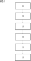
- Fig. 1 displays a computer-implemented method 10 for providing a first X-ray image and a second X-ray image acquired by an X-ray imaging system according to the invention.
- the method 10 comprises the following steps, preferably in the following order:
- the X-ray image dataset Before receiving 12 the X-ray image dataset, the X-ray image dataset can be acquired in a step 11. After providing 15 the first X-ray image and the second X-ray image, the first X-ray image and the second X-ray image can be displayed in step 16.
- the first X-ray image and the second X-ray image are displayed in a toggle mode. In an alternative embodiment, the first X-ray image and the second X-ray image are displayed concurrently.
- Applying a second image impression can comprise applying a trained algorithm to the X-ray image dataset, wherein the trained algorithm is based on a deep learning method or wherein the trained algorithm is based on a non-linear algorithm.
- the second image impression can mimic the use of another X-ray imaging system, the use of other acquisition parameters for acquiring the X-ray image dataset, and/or the use of other post-processing methods to the X-ray image dataset.
- the first X-ray image is appropriate for diagnostic evaluation.
- the first X-ray image and the second X-ray image comprise the same diagnostic relevant information.
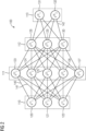
- Fig. 2 displays an embodiment of an artificial neural network 100.
- artificial neural network is “neural network”, “artificial neural net” or “neural net”.
- the artificial neural network 100 comprises nodes 120, ..., 132 and edges 140, ..., 142, wherein each edge 140, ..., 142 is a directed connection from a first node 120, ..., 132 to a second node 120, ..., 132.
- the first node 120, ..., 132 and the second node 120, ..., 132 are different nodes 120, ..., 132, it is also possible that the first node 120, ..., 132 and the second node 120, ..., 132 are identical.
- the edge 140 is a directed connection from the node 120 to the node 123
- the edge 142 is a directed connection from the node 130 to the node 132.
- An edge 140, ..., 142 from a first node 120, ..., 132 to a second node 120, ..., 132 is also denoted as "ingoing edge” for the second node 120, ..., 132 and as "outgoing edge” for the first node 120, ..., 132.
- the nodes 120, ..., 132 of the artificial neural network 100 can be arranged in layers 110, ..., 113, wherein the layers can comprise an intrinsic order introduced by the edges 140, ..., 142 between the nodes 120, ..., 132.
- edges 140, ..., 142 can exist only between neighboring layers of nodes.
- the number of hidden layers 111, 112 can be chosen arbitrarily.
- the number of nodes 120, ..., 122 within the input layer 110 usually relates to the number of input values of the neural network
- the number of nodes 131, 132 within the output layer 113 usually relates to the number of output values of the neural network.
- a (real) number can be assigned as a value to every node 120, ..., 132 of the neural network 100.
- x (n) i denotes the value of the i-th node 120, ..., 132 of the n-th layer 110, ..., 113.
- the values of the nodes 120, ..., 122 of the input layer 110 are equivalent to the input values of the neural network 100
- the values of the nodes 131, 132 of the output layer 113 are equivalent to the output value of the neural network 100.
- each edge 140, ..., 142 can comprise a weight being a real number, in particular, the weight is a real number within the interval [-1, 1] or within the interval [0, 1].
- w (m,n) i,j denotes the weight of the edge between the i-th node 120, ..., 132 of the m-th layer 110, ..., 113 and the j-th node 120, ..., 132 of the n-th layer 110, ..., 113.
- the abbreviation w (n) i,j is defined for the weight w (n,n+1) i,j .
- the function f is a transfer function (another term is "activation function").
- transfer functions are step functions, sigmoid function (e.g. the logistic function, the generalized logistic function, the hyperbolic tangent, the Arctangent function, the error function, the smoothstep function) or rectifier functions.
- the transfer function is mainly used for normalization purposes.
- the values are propagated layer-wise through the neural network, wherein values of the input layer 110 are given by the input of the neural network 100, wherein values of the first hidden layer 111 can be calculated based on the values of the input layer 110 of the neural network, wherein values of the second hidden layer 112 can be calculated based in the values of the first hidden layer 111, etc.
- training data comprises training input data and training output data (denoted as t i ).
- training output data denoted as t i .
- the neural network 100 is applied to the training input data to generate calculated output data.
- the training data and the calculated output data comprise a number of values, said number being equal with the number of nodes of the output layer.
- a comparison between the calculated output data and the training data is used to recursively adapt the weights within the neural network 100 (backpropagation algorithm).
- Fig. 3 displays an embodiment of a convolutional neural network 200.
- the convolutional neural network comprises 200 an input layer 210, a convolutional layer 211, a pooling layer 212, a fully connected layer 213 and an output layer 214.
- the convolutional neural network 200 can comprise several convolutional layers 211, several pooling layers 212 and several fully connected layers 213, as well as other types of layers.
- the order of the layers can be chosen arbitrarily, usually fully connected layers 213 are used as the last layers before the output layer 214.
- the nodes 220, ..., 224 of one layer 210, ..., 214 can be considered to be arranged as a d-dimensional matrix or as a d-dimensional image.
- the value of the node 220, ..., 224 indexed with i and j in the n-th layer 210, ..., 214 can be denoted as x (n) [i,j].
- the arrangement of the nodes 220, ..., 224 of one layer 210, ..., 214 does not have an effect on the calculations executed within the convolutional neural network 200 as such, since these are given solely by the structure and the weights of the edges.
- a convolutional layer 211 is characterized by the structure and the weights of the incoming edges forming a convolution operation based on a certain number of kernels.
- the k-th kernel K k is a d-dimensional matrix (in this embodiment a two-dimensional matrix), which is usually small compared to the number of nodes 220, ..., 224 (e.g. a 3x3 matrix, or a 5x5 matrix).
- a kernel being a 3x3 matrix, there are only 9 independent weights (each entry of the kernel matrix corresponding to one independent weight), irrespectively of the number of nodes 220, ..., 224 in the respective layer 210, ..., 214.
- the number of nodes 221 in the convolutional layer is equivalent to the number of nodes 220 in the preceding layer 210 multiplied with the number of kernels.
- nodes 220 of the preceding layer 210 are already arranged as a (d+1)-dimensional matrix comprising a depth dimension, using a plurality of kernels can be interpreted as expanding along the depth dimension, so that the nodes 221 of the convolutional layer 221 are arranged also as a (d+1)-dimensional matrix, wherein the size of the (d+1)-dimensional matrix with respect to the depth dimension is by a factor of the number of kernels larger than in the preceding layer 210.
- convolutional layers 211 The advantage of using convolutional layers 211 is that spatially local correlation of the input data can exploited by enforcing a local connectivity pattern between nodes of adjacent layers, in particular by each node being connected to only a small region of the nodes of the preceding layer.
- the input layer 210 comprises 36 nodes 220, arranged as a two-dimensional 6x6 matrix.
- the convolutional layer 211 comprises 72 nodes 221, arranged as two two-dimensional 6x6 matrices, each of the two matrices being the result of a convolution of the values of the input layer with a kernel. Equivalently, the nodes 221 of the convolutional layer 211 can be interpreted as arranges as a three-dimensional 6x6x2 matrix, wherein the last dimension is the depth dimension.
- a pooling layer 212 can be characterized by the structure and the weights of the incoming edges and the activation function of its nodes 222 forming a pooling operation based on a non-linear pooling function f.
- the number of nodes 221, 222 can be reduced, by replacing a number d 1 ⁇ d 2 of neighboring nodes 221 in the preceding layer 211 with a single node 222 being calculated as a function of the values of said number of neighboring nodes in the pooling layer.
- the pooling function f can be the max-function, the average or the L2-Norm.
- the weights of the incoming edges are fixed and are not modified by training.
- the advantage of using a pooling layer 212 is that the number of nodes 221, 222 and the number of parameters is reduced.
- the pooling layer 212 is a max-pooling, replacing four neighboring nodes with only one node, the value being the maximum of the values of the four neighboring nodes.
- the max-pooling is applied to each d-dimensional matrix of the previous layer; in this embodiment, the max-pooling is applied to each of the two two-dimensional matrices, reducing the number of nodes from 72 to 18.
- a fully-connected layer 213 can be characterized by the fact that a majority, in particular, all edges between nodes 222 of the previous layer 212 and the nodes 223 of the fully-connected layer 213 are present, and wherein the weight of each of the edges can be adjusted individually.
- the nodes 222 of the preceding layer 212 of the fully-connected layer 213 are displayed both as two-dimensional matrices, and additionally as non-related nodes (indicated as a line of nodes, wherein the number of nodes was reduced for a better presentability).
- the number of nodes 223 in the fully connected layer 213 is equal to the number of nodes 222 in the preceding layer 212.
- the number of nodes 222, 223 can differ.
- the values of the nodes 224 of the output layer 214 are determined by applying the Softmax function onto the values of the nodes 223 of the preceding layer 213.
- the Softmax function By applying the Softmax function, the sum of the values of all nodes 224 of the output layer is 1, and all values of all nodes 224 of the output layer are real numbers between 0 and 1.
- the values of the output layer can be interpreted as the probability of the input data falling into one of the different categories.
- a convolutional neural network 200 can also comprise a ReLU (acronym for "rectified linear units") layer.
- a ReLU layer is equivalent to the number of nodes and the structure of the nodes contained in the preceding layer.
- convolutional neural networks 200 can be trained based on the backpropagation algorithm.
- methods of regularization can be used, e.g. dropout of nodes 220, ..., 224, stochastic pooling, use of artificial data, weight decay based on the L1 or the L2 norm, or max norm constraints.
- a mammography system 301 in particular in the form of a tomosynthesis system, is shown by way of example and roughly schematically. Relative directions such as “above”, “below”, etc. refer to a tomosynthesis system set up for operation as intended.
- the mammography system 301 includes a tomosynthesis device 302 and a control device 312.
- the tomosynthesis device 302 has a standing column 307 and a source-detector arrangement 303, which in turn comprise an X-ray source 304 and an X-ray detector 305 with a detector area 5.1.
- Standing column 307 is in operation on the ground.
- the source-detector arrangement 303 can be connected to it in a movable manner, so that the height of the detector surface 305.1, i.e. the distance to the substrate, can be adjusted to a chest height of a patient.
- a breast O of the patient (shown schematically here) is the object of examination, the breast O, for an examination on the top of the detector surface 305.1.
- a compression plate 306 is arranged, which is movably connected to the source-detector arrangement 303.
- the breast O is compressed and at the same time fixed by lowering the compression plate 306 to it, so that pressure is applied on the breast O between compression plate 306 and detector surface 305.1.
- the X-ray emitter 304 is arranged and designed opposite the X-ray detector 305 in such a way that the X-ray detector 305 detects X-rays R emitted by it after at least part of the X-ray radiation R has penetrated the patient's breast O.
- the X-ray emitter 304 is relative to the X-ray detector 305 by means of a rotary arm 308, for example, in a range of ⁇ 25° around a basic position, in which it is perpendicular to the detector surface 305.1.
- the mammography system 301 can in particular a control device 12 and a computer unit with a training unit 310.
- the control device 312 is connected to a terminal 313, for example having a user interface or display unit, through which a user can communicate commands to the tomosynthesis system 301 or retrieve measurement results, for example the X-ray.
- the control device 312 may be located in the same room as the tomosynthesis device 302, but it may also be located in an adjacent control room or at an even greater spatial distance.
- Fig. 5 shows an exemplary embodiment of an X-ray (imaging) system 401, especially a radiography system, according to the invention.
- the X-ray system 401 has a patient positioning device 410 with a table 411 fixed to the floor 417.
- the object 413 lies on the table 411.
- the patient positioning device 410 further comprises an X-ray detector unit 418.
- the X-ray system 401 comprises an X-ray source 403 and an X-ray detector unit 418.
- the X-ray source unit 402 which comprises the X-ray source 403 and a collimator unit 404.
- the X-ray source unit 402 can be connected to the ceiling 407 of the examination room by means of a ceiling mount 406. By means of the ceiling mount 406, the X-ray source 403 can be moved.
- the X-ray system 401 may also comprise an input unit 421 and an output unit 422.
- the input unit 421 and the output unit 422 may be connected to the control unit 420.
- the control unit 420 may further comprise or be connected to the training unit 424.
Landscapes
- Health & Medical Sciences (AREA)
- Life Sciences & Earth Sciences (AREA)
- Engineering & Computer Science (AREA)
- Medical Informatics (AREA)
- Physics & Mathematics (AREA)
- Surgery (AREA)
- Heart & Thoracic Surgery (AREA)
- Veterinary Medicine (AREA)
- Biophysics (AREA)
- High Energy & Nuclear Physics (AREA)
- Public Health (AREA)
- Nuclear Medicine, Radiotherapy & Molecular Imaging (AREA)
- Optics & Photonics (AREA)
- Pathology (AREA)
- Radiology & Medical Imaging (AREA)
- Biomedical Technology (AREA)
- General Health & Medical Sciences (AREA)
- Molecular Biology (AREA)
- Animal Behavior & Ethology (AREA)
- General Physics & Mathematics (AREA)
- Oral & Maxillofacial Surgery (AREA)
- Theoretical Computer Science (AREA)
- Dentistry (AREA)
- Computer Vision & Pattern Recognition (AREA)
- Human Computer Interaction (AREA)
- Apparatus For Radiation Diagnosis (AREA)
Abstract
Description
- The invention relates to a computer-implemented method for providing a first X-ray image and a second X-ray image acquired by an X-ray imaging system, an X-ray imaging system, a computer program product, and a computer-readable medium, wherein an X-ray image can be provided with different image impressions to the user.
- An X-ray imaging system, e.g. a radiography system or a fluoroscopy system, comprises an X-ray source and an X-ray detector. The examination object, in particular a patient, is arranged between the X-ray source and the X-ray detector so that an X-ray image of an examination region can be acquired.
- A mammography system includes an X-ray source and an X-ray detector, with a breast arranged between the X-ray source and the X-ray detector. The examination area comprises the breast, especially the entire breast. In general, the breast is compressed or fixed by means of a compression unit. For this purpose, in particular, the surface of the X-ray detector or a housing of the X-ray detector and an essentially parallel arranged compression plate can be used. Furthermore, other forms of the compression unit are known. An X-ray data set can be generated. The X-ray data set may include a digital full-field mammography image and / or a tomosynthesis image.
- Modern mammography systems offer a tomosynthesis function to generate a series of projections that allow a three-dimensional representation of the breast using reconstructed layers. Here, the X-ray emitter or the X-ray source moves in an angular range of 15 to 50 degrees over the compressed breast. The digital full-field mammography image and the tomosynthesis image can also be acquired together within a single compression (per breast).
- X-rays images can have different image impressions called flavors. These flavors depend on the hardware used to record the x-ray images as well as on the operation principle and the parameter set of the applied reconstruction and post processing algorithm. The influence of the chosen recording system on the x-ray image impression can be observed in radiography as well as in mammography. For example, two reconstructed x-ray images of the same breast but recorded with a different parameter set of the post processing algorithm can exhibit different image impressions.
- Radiologists are used to a particular flavor or image impression. Changing or working with different image impression, e.g. depending on the body region, leads to a decrease in the reading time and the reliability of the diagnosis. This is especially problematic, if different x-ray images with different flavors must be compared against each other. However, there are several reasons, which make the use or exchange of various x-ray systems necessary: An x-ray system exchange or update with more recent technology increases the image quality and consequently the reliability of the diagnosis. An old x-ray machine must be replaced due to a defect, or a radiologist changes the working side.
- When a new system or software version is installed at a customer site, service specialists or image quality specialists can adjust post-processing parameters by hand together with the customer, using some example cases from the local PACS. This is very time consuming, and the results are not always satisfying. Especially for breast imaging, the style adjustment depends on the content of the example cases used for the adjustment process. Characteristics like the density of the breast, thickness or view can lead to different post-processing parameter sets in the end. To overcome this problem, several cases are used for this process, still leading to non-ideal results. And the problem is even stronger when adapting the style of another vendors system.
- It is an object of the invention to provide a computer-implemented method for providing a first X-ray image and a second X-ray image acquired by an X-ray imaging system, a computer program product, a computer-readable medium, and an X-ray imaging system, which makes it easier for the user to adapt to a new or different image impression.
- The object of the invention is solved by a computer-implemented method for providing a first X-ray image and a second X-ray image acquired by an X-ray imaging system according to
claim 1, an X-ray imaging system according to claim 12, a computer program product according toclaim 14, and a computer-readable medium according toclaim 15. - In the following the solution according to the invention is described with respect to the claimed systems as well as with respect to the claimed methods. Features, advantages or alternative embodiments herein can be assigned to the other claimed objects and vice versa. In other words, claims for the systems can be improved with features described or claimed in the context of the methods. In this case, the functional features of the method are embodied by objective units of the system.
- Furthermore, in the following the solution according to the invention is described with respect to methods and systems providing a first X-ray image and a second X-ray image acquired by an X-ray imaging system as well as with respect to methods and systems for the training of the trained function. Features, advantages or alternative embodiments herein can be assigned to the other claimed objects and vice versa. In other words, claims for methods and systems for training of the trained function can be improved with features described or claimed in context of the methods and systems providing a first X-ray image and a second X-ray image acquired by an X-ray imaging system, and vice versa.
- In particular, the trained function of the methods and systems providing a first X-ray image and a second X-ray image acquired by an X-ray imaging system can be adapted by the methods and systems for training of the trained function. Furthermore, the input data can comprise advantageous features and embodiments of the training input data, and vice versa. Furthermore, the output data can comprise advantageous features and embodiments of the output training data, and vice versa.
- The invention relates to a computer-implemented method for providing a first X-ray image and a second X-ray image acquired by an X-ray imaging system., comprising:
- Receiving an X-ray image dataset of an examination region,
- Applying a first image impression function to the X-ray image dataset and generating a first X-ray image with a first image impression,
- Applying a second image impression function to the X-ray image dataset and generating a second X-ray image with a second image impression,
- Providing the first X-ray image and the second X-ray image.
- The first and second image impression function can be a set of parameters which is applied to the X-ray image dataset. The first and second image impression function can be a trained function which is applied to the X-ray image dataset. The image impression can be defined by parameters like noise, contrast, artefact reduction algorithms and others.
- According to an aspect of the invention, the first X-ray image and the second X-ray image are displayed in a toggle mode.
- According to an aspect of the invention, the first X-ray image and the second X-ray image are displayed concurrently.
- According to an aspect of the invention, applying a second image impression comprises applying a trained algorithm to the X-ray image dataset.
- According to an aspect of the invention, the trained algorithm is based on a deep learning method.
- According to an aspect of the invention, the trained algorithm is based on a non-linear algorithm.
- According to an aspect of the invention, the second image impression mimics the use of another X-ray imaging system.
- According to an aspect of the invention, the second image impression mimics the use of other acquisition parameters for acquiring the X-ray image dataset.
- According to an aspect of the invention, the second image impression mimics the use of other post-processing methods to the X-ray image dataset.
- According to an aspect of the invention, the first X-ray image is appropriate for diagnostic evaluation.
- According to an aspect of the invention, the first X-ray image and the second X-ray image comprise the same diagnostic relevant information.
- The invention further relates to an X-ray imaging system for carrying out the method according to the invention.
- According to an aspect of the invention, the X-ray imaging system is a radiography system or a mammography system.
- The invention further relates to a computer program product comprising instructions which, when the program is executed by the X-ray imaging system according to the invention, cause the X-ray system to carry out the method according to the invention.
- The invention further relates to a computer-readable medium comprising instructions which, when executed by the X-ray imaging system according to the invention, cause the X-ray imaging system to carry out the method according to the invention.
- The invention further relates to a computer-implemented method for providing a trained function, comprising:
- receiving input training data, wherein the input training data comprises a first X-ray image with a first image impression,
- receiving output training data, wherein the output training data is related to the input training data, wherein the output training data comprises a second X-ray image with a second image impression,
- training a function based on the input training data and the output training data,
- providing the trained function.
- The invention further relates to a training system, comprising:
- A first training interface, configured for receiving input training data, wherein the input training data comprises a first X-ray image with a first image impression,
- A second training interface, configured for receiving output training data, wherein the output training data is related to the input training data, wherein the output training data comprises a second X-ray image with a second image impression,
- A training computation unit, configured for training a function based on the input training data and the output training data,
- A third training interface, configured for providing the trained function.
- In general, parameters of a trained function can be adapted by means of training. In particular, supervised training, semi-supervised training, unsupervised training, reinforcement learning and/or active learning can be used. Furthermore, representation learning (an alternative term is "feature learning") can be used. In particular, the parameters of the trained functions can be adapted iteratively by several steps of training.
- In particular, a trained function can comprise a neural network, a support vector machine, a decision tree and/or a Bayesian network, and/or the trained function can be based on k-means clustering, Q-learning, genetic algorithms and/or association rules. In particular, a neural network can be a deep neural network, a convolutional neural network or a convolutional deep neural network. Furthermore, a neural network can be an adversarial network, a deep adversarial network and/or a generative adversarial network.
- To help the radiologist to adapt to a new flavor or a different image impression, the inventors propose the use of an additional x-ray image besides the usual image which is used for diagnosis. The second x-ray image is basing on the same recording than the default image but is post-processed to have another flavor or image impression. The radiologist can be able to alternate or to toggle between the standard x-ray image and the additional one. The additional (second) image allows the radiologist to see flavor versions or different image impressions, which were used on previous systems or which he was used to. This is especially helpful, if several x-ray images with different flavors must be compared to each other, because the new x-ray images can be then also shown in another image impression, so that all images to be compared exhibit the same image impression. Furthermore, the additional flavor or additional image impression helps the radiologist during the transition to a new system and new image impression, since he is now able to switch back to his old version. He can then compare how different areas of the X-ray image are represented by the new image impression.
- Because of the existence of the first X-ray image, the second X-ray image must not be certified to be used for diagnosis. Hence it must not be proven that diagnostically relevant information is not altered. This allows more degrees of freedom in the development of the post processing chain for the second x-ray image.
- Machine learning algorithms for a style/flavor transfer or the transfer of image impressions can be used in particular. X-ray images with the image impression requested by the radiologist can serve as objective data to fit the parameter of the machine learning algorithm. The image impression of x-ray images from the new system can be then transformed to meet the image impression of the objective data by the algorithm. This transformation can take place on the post processed images, on raw images or unfinished processed x-ray images.
- The idea of an additional second X-ray image, which serves the radiologist as a reference image comprising a known image impression is helpful during the phase of moving to a new X-ray imaging system. The additional second image allows the radiologist to see image impression versions which were used on previous systems or which he was used to. This is especially helpful, if several x-ray images with different image impressions must be compared to each other because the new x-ray images can be also shown in another image impression, so that all X-ray images which must be compared have the same image impression. Furthermore, the additional image impression helps the radiologist by the transition to a new system and new image impression, since he is now able to switch back to his old version. He can then compare how different areas of the image are represented by the new image impression. Because of the existence of the first image, the second x-ray image must not be certified to be used for diagnosis. This additional image allows the use of machine learning algorithm to perform a style transfer or a transfer of image impression.
- Examples of embodiments of the invention are explained in more detail below by means of drawings.
-
FIG 1 a schematic representation of the method for providing a first X-ray image and a second X-ray image acquired by an X-ray imaging system; -
FIG 2 a schematic representation of a neural network according to the invention; and -
FIG 3 a schematic representation of a convolutional neural network according to the invention. -
FIG 4 a schematic representation of a mammography system; and -
FIG 5 a schematic representation of an X-ray imaging system. -
Fig. 1 displays a computer-implemented method 10 for providing a first X-ray image and a second X-ray image acquired by an X-ray imaging system according to the invention. The method 10 comprises the following steps, preferably in the following order: - Receiving 12 an X-ray image dataset of an examination region,
- Applying 13 a first image impression function to the X-ray image dataset and generating a first X-ray image with a first image impression,
- Applying 14 a second image impression function to the X-ray image dataset and generating a second X-ray image with a second image impression,
- Providing 15 the first X-ray image and the second X-ray image.
- Before receiving 12 the X-ray image dataset, the X-ray image dataset can be acquired in a
step 11. After providing 15 the first X-ray image and the second X-ray image, the first X-ray image and the second X-ray image can be displayed instep 16. - The first X-ray image and the second X-ray image are displayed in a toggle mode. In an alternative embodiment, the first X-ray image and the second X-ray image are displayed concurrently.
- Applying a second image impression can comprise applying a trained algorithm to the X-ray image dataset, wherein the trained algorithm is based on a deep learning method or wherein the trained algorithm is based on a non-linear algorithm.
- The second image impression can mimic the use of another X-ray imaging system, the use of other acquisition parameters for acquiring the X-ray image dataset, and/or the use of other post-processing methods to the X-ray image dataset. The first X-ray image is appropriate for diagnostic evaluation. The first X-ray image and the second X-ray image comprise the same diagnostic relevant information.
-
Fig. 2 displays an embodiment of an artificialneural network 100. Alternative terms for "artificial neural network" are "neural network", "artificial neural net" or "neural net". - The artificial
neural network 100 comprisesnodes 120, ..., 132 andedges 140, ..., 142, wherein eachedge 140, ..., 142 is a directed connection from afirst node 120, ..., 132 to asecond node 120, ..., 132. In general, thefirst node 120, ..., 132 and thesecond node 120, ..., 132 aredifferent nodes 120, ..., 132, it is also possible that thefirst node 120, ..., 132 and thesecond node 120, ..., 132 are identical. For example, inFig. 1 theedge 140 is a directed connection from thenode 120 to thenode 123, and theedge 142 is a directed connection from thenode 130 to thenode 132. Anedge 140, ..., 142 from afirst node 120, ..., 132 to asecond node 120, ..., 132 is also denoted as "ingoing edge" for thesecond node 120, ..., 132 and as "outgoing edge" for thefirst node 120, ..., 132. - In this embodiment, the
nodes 120, ..., 132 of the artificialneural network 100 can be arranged inlayers 110, ..., 113, wherein the layers can comprise an intrinsic order introduced by theedges 140, ..., 142 between thenodes 120, ..., 132. In particular, edges 140, ..., 142 can exist only between neighboring layers of nodes. In the displayed embodiment, there is aninput layer 110 comprisingonly nodes 120, ..., 122 without an incoming edge, anoutput layer 113 comprisingonly nodes hidden layers input layer 110 and theoutput layer 113. In general, the number ofhidden layers nodes 120, ..., 122 within theinput layer 110 usually relates to the number of input values of the neural network, and the number ofnodes output layer 113 usually relates to the number of output values of the neural network. - In particular, a (real) number can be assigned as a value to every
node 120, ..., 132 of theneural network 100. Here, x(n) i denotes the value of the i-th node 120, ..., 132 of the n-th layer 110, ..., 113. The values of thenodes 120, ..., 122 of theinput layer 110 are equivalent to the input values of theneural network 100, the values of thenodes output layer 113 are equivalent to the output value of theneural network 100. Furthermore, eachedge 140, ..., 142 can comprise a weight being a real number, in particular, the weight is a real number within the interval [-1, 1] or within the interval [0, 1]. Here, w(m,n) i,j denotes the weight of the edge between the i-th node 120, ..., 132 of the m-th layer 110, ..., 113 and the j-th node 120, ..., 132 of the n-th layer 110, ..., 113. Furthermore, the abbreviation w(n) i,j is defined for the weight w(n,n+1) i,j. - In particular, to calculate the output values of the
neural network 100, the input values are propagated through the neural network. In particular, the values of thenodes 120, ..., 132 of the (n+1)-th layer 110, ..., 113 can be calculated based on the values of thenodes 120, ..., 132 of the n-th layer 110, ..., 113 by
- Herein, the function f is a transfer function (another term is "activation function"). Known transfer functions are step functions, sigmoid function (e.g. the logistic function, the generalized logistic function, the hyperbolic tangent, the Arctangent function, the error function, the smoothstep function) or rectifier functions. The transfer function is mainly used for normalization purposes.
- In particular, the values are propagated layer-wise through the neural network, wherein values of the
input layer 110 are given by the input of theneural network 100, wherein values of the firsthidden layer 111 can be calculated based on the values of theinput layer 110 of the neural network, wherein values of the secondhidden layer 112 can be calculated based in the values of the firsthidden layer 111, etc. - In order to set the values w(m,n) i,j for the edges, the
neural network 100 has to be trained using training data. In particular, training data comprises training input data and training output data (denoted as ti). For a training step, theneural network 100 is applied to the training input data to generate calculated output data. In particular, the training data and the calculated output data comprise a number of values, said number being equal with the number of nodes of the output layer. - In particular, a comparison between the calculated output data and the training data is used to recursively adapt the weights within the neural network 100 (backpropagation algorithm). In particular, the weights are changed according to


output layer 113, wherein f' is the first derivative of the activation function, and y(n+1) j is the comparison training value for the j-th node of theoutput layer 113. -
Fig. 3 displays an embodiment of a convolutionalneural network 200. In the displayed embodiment, the convolutional neural network comprises 200 aninput layer 210, aconvolutional layer 211, apooling layer 212, a fully connectedlayer 213 and anoutput layer 214. Alternatively, the convolutionalneural network 200 can comprise severalconvolutional layers 211, several poolinglayers 212 and several fullyconnected layers 213, as well as other types of layers. The order of the layers can be chosen arbitrarily, usually fullyconnected layers 213 are used as the last layers before theoutput layer 214. - In particular, within a convolutional
neural network 200 thenodes 220, ..., 224 of onelayer 210, ..., 214 can be considered to be arranged as a d-dimensional matrix or as a d-dimensional image. In particular, in the two-dimensional case the value of thenode 220, ..., 224 indexed with i and j in the n-th layer 210, ..., 214 can be denoted as x(n) [i,j]. However, the arrangement of thenodes 220, ..., 224 of onelayer 210, ..., 214 does not have an effect on the calculations executed within the convolutionalneural network 200 as such, since these are given solely by the structure and the weights of the edges. - In particular, a
convolutional layer 211 is characterized by the structure and the weights of the incoming edges forming a convolution operation based on a certain number of kernels. In particular, the structure and the weights of the incoming edges are chosen such that the values x(n) k of thenodes 221 of theconvolutional layer 211 are calculated as a convolution x(n) k = Kk * x(n-1) based on the values x(n-1) of thenodes 220 of thepreceding layer 210, where the convolution * is defined in the two-dimensional case as
- Here the k-th kernel Kk is a d-dimensional matrix (in this embodiment a two-dimensional matrix), which is usually small compared to the number of
nodes 220, ..., 224 (e.g. a 3x3 matrix, or a 5x5 matrix). In particular, this implies that the weights of the incoming edges are not independent, but chosen such that they produce said convolution equation. In particular, for a kernel being a 3x3 matrix, there are only 9 independent weights (each entry of the kernel matrix corresponding to one independent weight), irrespectively of the number ofnodes 220, ..., 224 in therespective layer 210, ..., 214. In particular, for aconvolutional layer 211 the number ofnodes 221 in the convolutional layer is equivalent to the number ofnodes 220 in thepreceding layer 210 multiplied with the number of kernels. - If the
nodes 220 of thepreceding layer 210 are arranged as a d-dimensional matrix, using a plurality of kernels can be interpreted as adding a further dimension (denoted as "depth" dimension), so that thenodes 221 of theconvolutional layer 221 are arranged as a (d+1)-dimensional matrix. If thenodes 220 of thepreceding layer 210 are already arranged as a (d+1)-dimensional matrix comprising a depth dimension, using a plurality of kernels can be interpreted as expanding along the depth dimension, so that thenodes 221 of theconvolutional layer 221 are arranged also as a (d+1)-dimensional matrix, wherein the size of the (d+1)-dimensional matrix with respect to the depth dimension is by a factor of the number of kernels larger than in thepreceding layer 210. - The advantage of using
convolutional layers 211 is that spatially local correlation of the input data can exploited by enforcing a local connectivity pattern between nodes of adjacent layers, in particular by each node being connected to only a small region of the nodes of the preceding layer. - In the displayed embodiment, the
input layer 210 comprises 36nodes 220, arranged as a two-dimensional 6x6 matrix. Theconvolutional layer 211 comprises 72nodes 221, arranged as two two-dimensional 6x6 matrices, each of the two matrices being the result of a convolution of the values of the input layer with a kernel. Equivalently, thenodes 221 of theconvolutional layer 211 can be interpreted as arranges as a three-dimensional 6x6x2 matrix, wherein the last dimension is the depth dimension. - A
pooling layer 212 can be characterized by the structure and the weights of the incoming edges and the activation function of itsnodes 222 forming a pooling operation based on a non-linear pooling function f. For example, in the two dimensional case the values x(n) of thenodes 222 of thepooling layer 212 can be calculated based on the values x(n-1) of thenodes 221 of thepreceding layer 211 as
- In other words, by using a
pooling layer 212 the number ofnodes nodes 221 in thepreceding layer 211 with asingle node 222 being calculated as a function of the values of said number of neighboring nodes in the pooling layer. In particular, the pooling function f can be the max-function, the average or the L2-Norm. In particular, for apooling layer 212 the weights of the incoming edges are fixed and are not modified by training. - The advantage of using a
pooling layer 212 is that the number ofnodes - This leads to the amount of computation in the network being reduced and to a control of overfitting.
- In the displayed embodiment, the
pooling layer 212 is a max-pooling, replacing four neighboring nodes with only one node, the value being the maximum of the values of the four neighboring nodes. The max-pooling is applied to each d-dimensional matrix of the previous layer; in this embodiment, the max-pooling is applied to each of the two two-dimensional matrices, reducing the number of nodes from 72 to 18. - A fully-connected
layer 213 can be characterized by the fact that a majority, in particular, all edges betweennodes 222 of theprevious layer 212 and thenodes 223 of the fully-connectedlayer 213 are present, and wherein the weight of each of the edges can be adjusted individually. - In this embodiment, the
nodes 222 of thepreceding layer 212 of the fully-connectedlayer 213 are displayed both as two-dimensional matrices, and additionally as non-related nodes (indicated as a line of nodes, wherein the number of nodes was reduced for a better presentability). In this embodiment, the number ofnodes 223 in the fully connectedlayer 213 is equal to the number ofnodes 222 in thepreceding layer 212. Alternatively, the number ofnodes - Furthermore, in this embodiment the values of the nodes 224 of the
output layer 214 are determined by applying the Softmax function onto the values of thenodes 223 of thepreceding layer 213. By applying the Softmax function, the sum of the values of all nodes 224 of the output layer is 1, and all values of all nodes 224 of the output layer are real numbers between 0 and 1. In particular, if using the convolutionalneural network 200 for categorizing input data, the values of the output layer can be interpreted as the probability of the input data falling into one of the different categories. - A convolutional
neural network 200 can also comprise a ReLU (acronym for "rectified linear units") layer. In particular, the number of nodes and the structure of the nodes contained in a ReLU layer is equivalent to the number of nodes and the structure of the nodes contained in the preceding layer. In particular, the value of each node in the ReLU layer is calculated by applying a rectifying function to the value of the corresponding node of the preceding layer. Examples for rectifying functions are f(x) = max(0,x), the tangent hyperbolics function or the sigmoid function. - In particular, convolutional
neural networks 200 can be trained based on the backpropagation algorithm. For preventing overfitting, methods of regularization can be used, e.g. dropout ofnodes 220, ..., 224, stochastic pooling, use of artificial data, weight decay based on the L1 or the L2 norm, or max norm constraints. - In
Figure 4 , amammography system 301, in particular in the form of a tomosynthesis system, is shown by way of example and roughly schematically. Relative directions such as "above", "below", etc. refer to a tomosynthesis system set up for operation as intended. Themammography system 301 includes atomosynthesis device 302 and acontrol device 312. Thetomosynthesis device 302 has a standingcolumn 307 and a source-detector arrangement 303, which in turn comprise anX-ray source 304 and anX-ray detector 305 with a detector area 5.1. Standingcolumn 307 is in operation on the ground. The source-detector arrangement 303 can be connected to it in a movable manner, so that the height of the detector surface 305.1, i.e. the distance to the substrate, can be adjusted to a chest height of a patient. - A breast O of the patient (shown schematically here) is the object of examination, the breast O, for an examination on the top of the detector surface 305.1. Above the chest O and the detector surface 305.1 a
compression plate 306 is arranged, which is movably connected to the source-detector arrangement 303. For the examination, the breast O is compressed and at the same time fixed by lowering thecompression plate 306 to it, so that pressure is applied on the breast O betweencompression plate 306 and detector surface 305.1. - The
X-ray emitter 304 is arranged and designed opposite theX-ray detector 305 in such a way that theX-ray detector 305 detects X-rays R emitted by it after at least part of the X-ray radiation R has penetrated the patient's breast O. TheX-ray emitter 304 is relative to theX-ray detector 305 by means of arotary arm 308, for example, in a range of ± 25° around a basic position, in which it is perpendicular to the detector surface 305.1. - The
mammography system 301 can in particular a control device 12 and a computer unit with atraining unit 310. Thecontrol device 312 is connected to a terminal 313, for example having a user interface or display unit, through which a user can communicate commands to thetomosynthesis system 301 or retrieve measurement results, for example the X-ray. Thecontrol device 312 may be located in the same room as thetomosynthesis device 302, but it may also be located in an adjacent control room or at an even greater spatial distance. -
Fig. 5 shows an exemplary embodiment of an X-ray (imaging)system 401, especially a radiography system, according to the invention. TheX-ray system 401 has apatient positioning device 410 with a table 411 fixed to thefloor 417. Theobject 413 lies on the table 411. Thepatient positioning device 410 further comprises anX-ray detector unit 418. - The
X-ray system 401 comprises anX-ray source 403 and anX-ray detector unit 418. TheX-ray source unit 402, which comprises theX-ray source 403 and acollimator unit 404. TheX-ray source unit 402 can be connected to theceiling 407 of the examination room by means of aceiling mount 406. By means of theceiling mount 406, theX-ray source 403 can be moved. - The
X-ray system 401 may also comprise aninput unit 421 and anoutput unit 422. Theinput unit 421 and theoutput unit 422 may be connected to the control unit 420. The control unit 420 may further comprise or be connected to the training unit 424. - Although the invention has been further illustrated in detail by the preferred embodiments, the invention is not limited by the disclosed examples and other variations may be derived therefrom by those skilled in the art without departing from the scope of protection of the invention.
Claims (15)
- A computer-implemented method (10) for providing a first X-ray image and a second X-ray image acquired by an X-ray imaging system, comprising:- Receiving (12) an X-ray image dataset of an examination region,- Applying (13) a first image impression function to the X-ray image dataset and generating a first X-ray image with a first image impression,- Applying (14) a second image impression function to the X-ray image dataset and generating a second X-ray image with a second image impression,- Providing (15) the first X-ray image and the second X-ray image.
- A method according to claim 1, wherein the first X-ray image and the second X-ray image are displayed in a toggle mode.
- A method according to claim 1, wherein the first X-ray image and the second X-ray image are displayed concurrently.
- A method according to the preceding claims, wherein applying a second image impression comprises applying a trained algorithm to the X-ray image dataset.
- A method according to claim 4, wherein the trained algorithm is based on a deep learning method.
- A method according to claim 4, wherein the trained algorithm is based on a non-linear algorithm.
- A method according to the preceding claims, wherein the second image impression mimics the use of another X-ray imaging system.
- A method according to the preceding claims, wherein the second image impression mimics the use of other acquisition parameters for acquiring the X-ray image dataset.
- A method according to the preceding claims, wherein the second image impression mimics the use of other post-processing methods to the X-ray image dataset.
- A method according to the preceding claims, wherein the first X-ray image is appropriate for diagnostic evaluation.
- A method according to the preceding claims, wherein the first X-ray image and the second X-ray image comprise the same diagnostic relevant information.
- An X-ray imaging system (401) for carrying out the method according to the claims 1 to 11.
- An X-ray imaging system according to claim 12, wherein the X-ray imaging system is a radiography system or a mammography system (301).
- A computer program product comprising instructions which, when the program is executed by the X-ray imaging system according to one of the claims 12 to 13, cause the X-ray system to carry out the method according to one of the claims 1 to 11.
- A computer-readable medium comprising instructions which, when executed by the X-ray imaging system according to one of the claims 12 to 13, cause the X-ray imaging system to carry out the method according to one of the claims 1 to 11.
Priority Applications (1)
| Application Number | Priority Date | Filing Date | Title |
|---|---|---|---|
| EP22198710.0A EP4344644A1 (en) | 2022-09-29 | 2022-09-29 | Computer-implemented method for providing a first x-ray image and a second x-ray image acquired by an x-ray imaging system |
Applications Claiming Priority (1)
| Application Number | Priority Date | Filing Date | Title |
|---|---|---|---|
| EP22198710.0A EP4344644A1 (en) | 2022-09-29 | 2022-09-29 | Computer-implemented method for providing a first x-ray image and a second x-ray image acquired by an x-ray imaging system |
Publications (1)
| Publication Number | Publication Date |
|---|---|
| EP4344644A1 true EP4344644A1 (en) | 2024-04-03 |
Family
ID=83508721
Family Applications (1)
| Application Number | Title | Priority Date | Filing Date |
|---|---|---|---|
| EP22198710.0A Pending EP4344644A1 (en) | 2022-09-29 | 2022-09-29 | Computer-implemented method for providing a first x-ray image and a second x-ray image acquired by an x-ray imaging system |
Country Status (1)
| Country | Link |
|---|---|
| EP (1) | EP4344644A1 (en) |
Citations (5)
| Publication number | Priority date | Publication date | Assignee | Title |
|---|---|---|---|---|
| US20130051527A1 (en) * | 2011-07-07 | 2013-02-28 | Takuya Sakaguchi | Image processing apparatus and method, and x-ray diagnostic apparatus |
| EP2722003A1 (en) * | 2012-10-18 | 2014-04-23 | Dental Imaging Technologies Corporation | Light box effect for viewing digital radiographic images |
| US20200163638A1 (en) * | 2018-11-23 | 2020-05-28 | Siemens Healthcare Gmbh | Synthetic mammogram with imprinted image impression |
| US20220092768A1 (en) * | 2020-09-24 | 2022-03-24 | GE Precision Healthcare LLC | Generating enhanced x-ray images |
| US20220096033A1 (en) * | 2020-09-30 | 2022-03-31 | Siemens Healthcare Gmbh | Method And Apparatus For Reconstructing Images |
-
2022
- 2022-09-29 EP EP22198710.0A patent/EP4344644A1/en active Pending
Patent Citations (5)
| Publication number | Priority date | Publication date | Assignee | Title |
|---|---|---|---|---|
| US20130051527A1 (en) * | 2011-07-07 | 2013-02-28 | Takuya Sakaguchi | Image processing apparatus and method, and x-ray diagnostic apparatus |
| EP2722003A1 (en) * | 2012-10-18 | 2014-04-23 | Dental Imaging Technologies Corporation | Light box effect for viewing digital radiographic images |
| US20200163638A1 (en) * | 2018-11-23 | 2020-05-28 | Siemens Healthcare Gmbh | Synthetic mammogram with imprinted image impression |
| US20220092768A1 (en) * | 2020-09-24 | 2022-03-24 | GE Precision Healthcare LLC | Generating enhanced x-ray images |
| US20220096033A1 (en) * | 2020-09-30 | 2022-03-31 | Siemens Healthcare Gmbh | Method And Apparatus For Reconstructing Images |
Similar Documents
| Publication | Publication Date | Title |
|---|---|---|
| EP3633601B1 (en) | Patient-specific deep learning image denoising methods and systems | |
| US11908568B2 (en) | System and methods for radiographic image quality assessment and protocol optimization | |
| US11308613B2 (en) | Synthesis of contrast enhanced medical images | |
| EP4141788A1 (en) | Fully automated assessment of coronary vulnerable plaque in coronary ct images using radiomic features | |
| US12053320B2 (en) | Computer-implemented method, computer program, systems and x-ray facility for correction of x-ray image data with regard to noise effects | |
| US20220156918A1 (en) | Automatic, dynamic, and adaptive slice planning for cardiac mri acquisition | |
| US11908047B2 (en) | Generating synthetic x-ray images and object annotations from CT scans for augmenting x-ray abnormality assessment systems | |
| CN113673710A (en) | Computer-implemented method and system for training an evaluation algorithm | |
| EP4487781B1 (en) | Ai-based medical imaging analysis of photon counting data | |
| US20250278895A1 (en) | Three dimensional organ reconstruction from two dimensional sparse imaging data | |
| EP4345766A1 (en) | Computer-implemented method for providing a de-identified medical image | |
| US20220405897A1 (en) | Computer-implemented methods and systems for provision of a correction algorithm for an x-ray image and for correction of an x-ray image, x-ray facility, computer program, and electronically readable data medium | |
| EP4345742B1 (en) | Computer-implemented method for providing a positioning score regarding a positioning of an examining region in an x-ray image | |
| EP4345753A2 (en) | Ct reconstruction for machine consumption | |
| US12567150B2 (en) | Editing presegmented images and volumes using deep learning | |
| EP4212101B1 (en) | Providing a complete set of key elements in an x-ray image | |
| EP4212090B1 (en) | Providing key elements of the examination region in an x-ray image | |
| US20250014174A1 (en) | Training ai systems on photon counting data | |
| EP4495877A1 (en) | Computer-implemented method for determining a reliability score | |
| US20250331801A1 (en) | Denoising in x-ray imaging | |
| EP4631435A1 (en) | Computer-aided diagnosis system for pulmonary nodule analysis using pcct images | |
| EP4345833A1 (en) | Computer-implemented method for a post-acquisition check of an x-ray image dataset | |
| EP4235580B1 (en) | Computer-implemented method for determining nuclear medical image data sets in dynamic nuclear medical imaging, determining device, computer program and electronically readable storage medium | |
| EP4715838A1 (en) | Advanced pulmonary nodule analysis system with malignancy-weighted detection and customized visualization | |
| US20260080551A1 (en) | Registration of intravascular and non-invasive vascular images for training ai models |
Legal Events
| Date | Code | Title | Description |
|---|---|---|---|
| PUAI | Public reference made under article 153(3) epc to a published international application that has entered the european phase |
Free format text: ORIGINAL CODE: 0009012 |
|
| STAA | Information on the status of an ep patent application or granted ep patent |
Free format text: STATUS: THE APPLICATION HAS BEEN PUBLISHED |
|
| AK | Designated contracting states |
Kind code of ref document: A1 Designated state(s): AL AT BE BG CH CY CZ DE DK EE ES FI FR GB GR HR HU IE IS IT LI LT LU LV MC MK MT NL NO PL PT RO RS SE SI SK SM TR |
|
| STAA | Information on the status of an ep patent application or granted ep patent |
Free format text: STATUS: REQUEST FOR EXAMINATION WAS MADE |
|
| 17P | Request for examination filed |
Effective date: 20240719 |
|
| RBV | Designated contracting states (corrected) |
Designated state(s): AL AT BE BG CH CY CZ DE DK EE ES FI FR GB GR HR HU IE IS IT LI LT LU LV MC MK MT NL NO PL PT RO RS SE SI SK SM TR |
|
| STAA | Information on the status of an ep patent application or granted ep patent |
Free format text: STATUS: EXAMINATION IS IN PROGRESS |
|
| 17Q | First examination report despatched |
Effective date: 20250722 |