EP4344635A1 - Driver abnormality sign detection apparatus - Google Patents
Driver abnormality sign detection apparatus Download PDFInfo
- Publication number
- EP4344635A1 EP4344635A1 EP23164212.5A EP23164212A EP4344635A1 EP 4344635 A1 EP4344635 A1 EP 4344635A1 EP 23164212 A EP23164212 A EP 23164212A EP 4344635 A1 EP4344635 A1 EP 4344635A1
- Authority
- EP
- European Patent Office
- Prior art keywords
- driver
- visual recognition
- abnormality sign
- recognition required
- required point
- Prior art date
- Legal status (The legal status is an assumption and is not a legal conclusion. Google has not performed a legal analysis and makes no representation as to the accuracy of the status listed.)
- Pending
Links
Images


Classifications
-
- B—PERFORMING OPERATIONS; TRANSPORTING
- B60—VEHICLES IN GENERAL
- B60W—CONJOINT CONTROL OF VEHICLE SUB-UNITS OF DIFFERENT TYPE OR DIFFERENT FUNCTION; CONTROL SYSTEMS SPECIALLY ADAPTED FOR HYBRID VEHICLES; ROAD VEHICLE DRIVE CONTROL SYSTEMS FOR PURPOSES NOT RELATED TO THE CONTROL OF A PARTICULAR SUB-UNIT
- B60W40/00—Estimation or calculation of non-directly measurable driving parameters for road vehicle drive control systems not related to the control of a particular sub unit, e.g. by using mathematical models
- B60W40/08—Estimation or calculation of non-directly measurable driving parameters for road vehicle drive control systems not related to the control of a particular sub unit, e.g. by using mathematical models related to drivers or passengers
-
- A—HUMAN NECESSITIES
- A61—MEDICAL OR VETERINARY SCIENCE; HYGIENE
- A61B—DIAGNOSIS; SURGERY; IDENTIFICATION
- A61B5/00—Measuring for diagnostic purposes; Identification of persons
- A61B5/16—Devices for psychotechnics; Testing reaction times ; Devices for evaluating the psychological state
- A61B5/163—Devices for psychotechnics; Testing reaction times ; Devices for evaluating the psychological state by tracking eye movement, gaze, or pupil change
-
- A—HUMAN NECESSITIES
- A61—MEDICAL OR VETERINARY SCIENCE; HYGIENE
- A61B—DIAGNOSIS; SURGERY; IDENTIFICATION
- A61B5/00—Measuring for diagnostic purposes; Identification of persons
- A61B5/16—Devices for psychotechnics; Testing reaction times ; Devices for evaluating the psychological state
- A61B5/18—Devices for psychotechnics; Testing reaction times ; Devices for evaluating the psychological state for vehicle drivers or machine operators
-
- A—HUMAN NECESSITIES
- A61—MEDICAL OR VETERINARY SCIENCE; HYGIENE
- A61B—DIAGNOSIS; SURGERY; IDENTIFICATION
- A61B5/00—Measuring for diagnostic purposes; Identification of persons
- A61B5/74—Details of notification to user or communication with user or patient; User input means
- A61B5/742—Details of notification to user or communication with user or patient; User input means using visual displays
-
- B—PERFORMING OPERATIONS; TRANSPORTING
- B60—VEHICLES IN GENERAL
- B60W—CONJOINT CONTROL OF VEHICLE SUB-UNITS OF DIFFERENT TYPE OR DIFFERENT FUNCTION; CONTROL SYSTEMS SPECIALLY ADAPTED FOR HYBRID VEHICLES; ROAD VEHICLE DRIVE CONTROL SYSTEMS FOR PURPOSES NOT RELATED TO THE CONTROL OF A PARTICULAR SUB-UNIT
- B60W40/00—Estimation or calculation of non-directly measurable driving parameters for road vehicle drive control systems not related to the control of a particular sub unit, e.g. by using mathematical models
- B60W40/02—Estimation or calculation of non-directly measurable driving parameters for road vehicle drive control systems not related to the control of a particular sub unit, e.g. by using mathematical models related to ambient conditions
-
- B—PERFORMING OPERATIONS; TRANSPORTING
- B60—VEHICLES IN GENERAL
- B60W—CONJOINT CONTROL OF VEHICLE SUB-UNITS OF DIFFERENT TYPE OR DIFFERENT FUNCTION; CONTROL SYSTEMS SPECIALLY ADAPTED FOR HYBRID VEHICLES; ROAD VEHICLE DRIVE CONTROL SYSTEMS FOR PURPOSES NOT RELATED TO THE CONTROL OF A PARTICULAR SUB-UNIT
- B60W50/00—Details of control systems for road vehicle drive control not related to the control of a particular sub-unit, e.g. process diagnostic or vehicle driver interfaces
- B60W50/08—Interaction between the driver and the control system
- B60W50/14—Means for informing the driver, warning the driver or prompting a driver intervention
-
- G—PHYSICS
- G06—COMPUTING OR CALCULATING; COUNTING
- G06V—IMAGE OR VIDEO RECOGNITION OR UNDERSTANDING
- G06V20/00—Scenes; Scene-specific elements
- G06V20/50—Context or environment of the image
- G06V20/59—Context or environment of the image inside of a vehicle, e.g. relating to seat occupancy, driver state or inner lighting conditions
- G06V20/597—Recognising the driver's state or behaviour, e.g. attention or drowsiness
-
- B—PERFORMING OPERATIONS; TRANSPORTING
- B60—VEHICLES IN GENERAL
- B60W—CONJOINT CONTROL OF VEHICLE SUB-UNITS OF DIFFERENT TYPE OR DIFFERENT FUNCTION; CONTROL SYSTEMS SPECIALLY ADAPTED FOR HYBRID VEHICLES; ROAD VEHICLE DRIVE CONTROL SYSTEMS FOR PURPOSES NOT RELATED TO THE CONTROL OF A PARTICULAR SUB-UNIT
- B60W40/00—Estimation or calculation of non-directly measurable driving parameters for road vehicle drive control systems not related to the control of a particular sub unit, e.g. by using mathematical models
- B60W40/08—Estimation or calculation of non-directly measurable driving parameters for road vehicle drive control systems not related to the control of a particular sub unit, e.g. by using mathematical models related to drivers or passengers
- B60W2040/0818—Inactivity or incapacity of driver
-
- B—PERFORMING OPERATIONS; TRANSPORTING
- B60—VEHICLES IN GENERAL
- B60W—CONJOINT CONTROL OF VEHICLE SUB-UNITS OF DIFFERENT TYPE OR DIFFERENT FUNCTION; CONTROL SYSTEMS SPECIALLY ADAPTED FOR HYBRID VEHICLES; ROAD VEHICLE DRIVE CONTROL SYSTEMS FOR PURPOSES NOT RELATED TO THE CONTROL OF A PARTICULAR SUB-UNIT
- B60W40/00—Estimation or calculation of non-directly measurable driving parameters for road vehicle drive control systems not related to the control of a particular sub unit, e.g. by using mathematical models
- B60W40/08—Estimation or calculation of non-directly measurable driving parameters for road vehicle drive control systems not related to the control of a particular sub unit, e.g. by using mathematical models related to drivers or passengers
- B60W2040/0818—Inactivity or incapacity of driver
- B60W2040/0827—Inactivity or incapacity of driver due to sleepiness
-
- B—PERFORMING OPERATIONS; TRANSPORTING
- B60—VEHICLES IN GENERAL
- B60W—CONJOINT CONTROL OF VEHICLE SUB-UNITS OF DIFFERENT TYPE OR DIFFERENT FUNCTION; CONTROL SYSTEMS SPECIALLY ADAPTED FOR HYBRID VEHICLES; ROAD VEHICLE DRIVE CONTROL SYSTEMS FOR PURPOSES NOT RELATED TO THE CONTROL OF A PARTICULAR SUB-UNIT
- B60W50/00—Details of control systems for road vehicle drive control not related to the control of a particular sub-unit, e.g. process diagnostic or vehicle driver interfaces
- B60W50/08—Interaction between the driver and the control system
- B60W50/14—Means for informing the driver, warning the driver or prompting a driver intervention
- B60W2050/143—Alarm means
-
- B—PERFORMING OPERATIONS; TRANSPORTING
- B60—VEHICLES IN GENERAL
- B60W—CONJOINT CONTROL OF VEHICLE SUB-UNITS OF DIFFERENT TYPE OR DIFFERENT FUNCTION; CONTROL SYSTEMS SPECIALLY ADAPTED FOR HYBRID VEHICLES; ROAD VEHICLE DRIVE CONTROL SYSTEMS FOR PURPOSES NOT RELATED TO THE CONTROL OF A PARTICULAR SUB-UNIT
- B60W2420/00—Indexing codes relating to the type of sensors based on the principle of their operation
- B60W2420/40—Photo, light or radio wave sensitive means, e.g. infrared sensors
- B60W2420/403—Image sensing, e.g. optical camera
-
- B—PERFORMING OPERATIONS; TRANSPORTING
- B60—VEHICLES IN GENERAL
- B60W—CONJOINT CONTROL OF VEHICLE SUB-UNITS OF DIFFERENT TYPE OR DIFFERENT FUNCTION; CONTROL SYSTEMS SPECIALLY ADAPTED FOR HYBRID VEHICLES; ROAD VEHICLE DRIVE CONTROL SYSTEMS FOR PURPOSES NOT RELATED TO THE CONTROL OF A PARTICULAR SUB-UNIT
- B60W2540/00—Input parameters relating to occupants
- B60W2540/225—Direction of gaze
-
- B—PERFORMING OPERATIONS; TRANSPORTING
- B60—VEHICLES IN GENERAL
- B60W—CONJOINT CONTROL OF VEHICLE SUB-UNITS OF DIFFERENT TYPE OR DIFFERENT FUNCTION; CONTROL SYSTEMS SPECIALLY ADAPTED FOR HYBRID VEHICLES; ROAD VEHICLE DRIVE CONTROL SYSTEMS FOR PURPOSES NOT RELATED TO THE CONTROL OF A PARTICULAR SUB-UNIT
- B60W2540/00—Input parameters relating to occupants
- B60W2540/229—Attention level, e.g. attentive to driving, reading or sleeping
-
- B—PERFORMING OPERATIONS; TRANSPORTING
- B60—VEHICLES IN GENERAL
- B60W—CONJOINT CONTROL OF VEHICLE SUB-UNITS OF DIFFERENT TYPE OR DIFFERENT FUNCTION; CONTROL SYSTEMS SPECIALLY ADAPTED FOR HYBRID VEHICLES; ROAD VEHICLE DRIVE CONTROL SYSTEMS FOR PURPOSES NOT RELATED TO THE CONTROL OF A PARTICULAR SUB-UNIT
- B60W2556/00—Input parameters relating to data
- B60W2556/45—External transmission of data to or from the vehicle
- B60W2556/50—External transmission of data to or from the vehicle of positioning data, e.g. GPS [Global Positioning System] data
Definitions
- the present invention relates to a driver abnormality sign detection apparatus for detecting an abnormality sign state of a driver during driving of a vehicle.
- Patent document 1 a driver state detection apparatus that detects an abnormal state of a driver of a vehicle has been proposed (for example, see Patent document 1).
- an amplitude and a frequency of the vehicle driver's saccade jumping eye motion of the driver to intentionally move his/her eye gaze
- an attention level is detected that is increased as the number of caution points to be checked by the driver during travel is increased in vehicle outside environment, so as to detect the abnormality of the driver on the basis of the attention level and the amplitude and the frequency of the driver's saccade.
- the invention has been made to solve such a problem and therefore has a purpose of providing a driver abnormality sign detection apparatus capable of detecting an abnormality sign state of a driver at a stage sufficiently earlier than onset of an abnormal state where the driver has difficulty in driving.
- the invention is a driver abnormality sign detection apparatus that detects an abnormality sign state of a driver who drives a vehicle, and includes: a travel environment information acquisition device that acquires travel environment information of the vehicle; an eye gaze tracker (to which is sometimes referred to as sightline detector) that detects the driver's eye gaze; and a controller configured to detect the driver's abnormality sign state on the basis of the travel environment information and the driver's eye gaze (to which is sometimes referred to as driver's sightline).
- a travel environment information acquisition device that acquires travel environment information of the vehicle
- an eye gaze tracker to which is sometimes referred to as sightline detector
- a controller configured to detect the driver's abnormality sign state on the basis of the travel environment information and the driver's eye gaze (to which is sometimes referred to as driver's sightline).
- the controller is configured to: identify a visual recognition required point to be visually recognized by the driver on the basis of the travel environment information; determine whether the driver has visually recognized the visual recognition required point on the basis of the driver's eye gaze; and detect the driver's abnormality sign state on the basis of a fact that the driver has not visually recognized the visual recognition required point.
- the controller identifies the visual recognition required point to be visually recognized by the driver on the basis of the travel environment information, determines whether the driver has visually recognized the visual recognition required point on the basis of the the driver's eye gaze, and detects the driver's abnormality sign state on the basis of the fact that the driver has not visually recognized the visual recognition required point.
- the abnormality sign state by using a fact that the driver has not been able to visually recognize the visual recognition required point due to a decline in a distributive attention function or a reduction in an effective visual field at an initial stage of a decline in the driver's attention function.
- the controller is configured to: determine that the driver has visually recognized the visual recognition required point in the case where the driver's eye gaze is directed within a specified range including the visual recognition required point; and, preferably, detect the driver's abnormality sign state on the basis of the number of the visual recognition required point not visually recognized by the driver.
- the driver's abnormality sign state is detected on the basis of the number of the visual recognition required point to which the driver's eye gaze is not directed.
- the abnormality sign state can be detected on the basis of the severity of missing of the visual recognition required point. In this way, it is possible to appropriately detect the driver's abnormality sign state at the stage sufficiently earlier than the onset of the abnormal state where the driver has difficulty in driving.
- the controller is configured to detect the driver's abnormality sign state in the case where a ratio of the number of the visual recognition required point not visually recognized by the driver to the total number of the visual recognition required points is equal to or larger than a specified value.
- the abnormality sign state can be detected. In this way, it is possible to appropriately detect the driver's abnormality sign state at the stage sufficiently earlier than the onset of the abnormal state where the driver has difficulty in driving.
- the controller is configured to: estimate a size of an effective visual field that can be visually recognized by the driver on the basis of a distance between the driver's sightline or the driver's eye gaze and the visual recognition required point not visually recognized by the driver; and detect the driver's abnormality sign state in the case where the estimated effective visual field size is smaller than the specified value.
- the abnormality sign state can be detected by estimating the degree of the narrowness of the effective visual field. In this way, it is possible to appropriately detect the driver's abnormality sign state at the stage sufficiently earlier than the onset of the abnormal state where the driver has difficulty in driving.
- the controller is configured to estimate the size of the effective visual field by comparing a minimum value of the angles of the driver's head with respect to at least one visual recognition required point that has not been visually recognized and the driver's eye gaze with a maximum value of the angles of the driver's head with respect to at least one visual recognition required point that has been visually recognized and the driver's eye gaze.
- the controller is configured to estimate the size of the effective visual field by being an intermediate value, preferably a mean value, between the minimum value of the angles of the driver's head with respect to at least one visual recognition required point that has not been visually recognized and the driver's eye gaze and the maximum value of the angles of the driver's head with respect to at least one visual recognition required point that has been visually recognized and the driver's eye gaze.
- the driver abnormality sign detection apparatus further includes an information output device that outputs information to the driver.
- the controller is configured to cause the information output device to output information that is used to guide the driver's eye gaze to the visual recognition required point in the case where the driver's abnormality sign state is detected.
- the driver's eye gaze is guided to the visual recognition required point. Therefore, it is possible to provide the appropriate driver assistance to the driver who starts missing the visual recognition required point at the initial stage of the decline in the attention function.
- the travel environment information acquisition device (21-24) for acquiring travel environment information of the vehicle (1) comprises at least one of: an outside camera (21) for capturing an image around the vehicle (1), a radar (22) for measuring a position and a speed of an object with respect to the vehicle (1), a navigation system (23) for providing map information to the controller (10), and a speed sensor for detecting a speed of the vehicle (1).
- the eye gaze tracker comprises an in-vehicle camera for capturing an image of the driver of the vehicle (1).
- the driver abnormality sign detection apparatus further comprises:
- the controller (10) is adapted to determine that the driver has not visually recognized the visual recognition required point, in the case where the driver's eye gaze is directed within a specified range including the visual recognition required point, and, thereafter, the driving operation performed by the driver of the vehicle fails to correspond to the visual recognition required point.
- the driving operation detector (25-31) comprises at least one of: a vehicle speed sensor (25) for detecting a speed of the vehicle (1), a yaw rate sensor (27) for detecting a yaw rate of the vehicle (1), a steering angle sensor (28) for detecting a rotation angle of a steering wheel (5), a steering torque sensor (29) for detecting torque applied to a steering shaft via a steering wheel (5), an acceleration sensor (26, 30) for detecting an depression amount of an accelerator pedal, and a brake sensor (31) for detecting a depression amount of a brake pedal.
- a vehicle speed sensor (25) for detecting a speed of the vehicle (1)
- a yaw rate sensor for detecting a yaw rate of the vehicle (1)
- a steering angle sensor (28) for detecting a rotation angle of a steering wheel (5)
- a steering torque sensor (29) for detecting torque applied to a steering shaft via a steering wheel (5)
- an acceleration sensor (26, 30) for detecting an depression amount of an accelerator
- the visual recognition required point is a red light or a stop sign
- the driving operation corresponding thereto is the decelerating operation.
- the driver abnormality sign detection apparatus further comprises a visual recognition required point database in which the travel environment and the visual recognition required points are stored in a mutually corresponding manner, for identifying the visual recognition required points to be visually recognized by the driver on basis of the current travel environment detected by the travel environment information acquisition device.
- the invention is further directed to a vehicle comprising the driver abnormality sign detection apparatus according to the invention.
- the driver's abnormality sign state can be detected at the stage sufficiently earlier than the abnormal state where the driver has difficulty in driving.
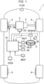
- Fig. 1 is an explanatory view of a vehicle on which the driver abnormality sign detection apparatus is mounted
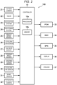
- Fig. 2 is a block diagram of the driver abnormality sign detection apparatus.
- a vehicle 1 includes: drive power sources 2 such as an engine and an electric motor that output drive power; a transmission 3 that transmits the drive power output from the drive power source 2 to drive wheels; a brake 4 that applies a braking force to the vehicle 1; and a steering device 5 for steering the vehicle 1.
- drive power sources 2 such as an engine and an electric motor that output drive power
- a transmission 3 that transmits the drive power output from the drive power source 2 to drive wheels
- a brake 4 that applies a braking force to the vehicle 1
- a steering device 5 for steering the vehicle 1.
- a driver abnormality sign detection apparatus 100 is configured to detect an abnormality sign state of a driver of the vehicle 1 and to execute control of the vehicle 1 and driving assistance control when necessary. As illustrated in Fig. 2 , the driver abnormality sign detection apparatus 100 has a controller 10, plural sensors, plural control systems, and plural information output devices.
- the plural sensors include an outside camera 21 and a radar 22 for acquiring travel environment information of the vehicle 1 as well as a navigation system 23 and a positioning system 24 for detecting a position of the vehicle 1.
- the plural sensors also include a vehicle speed sensor 25, an acceleration sensor 26, a yaw rate sensor 27, a steering angle sensor 28, a steering torque sensor 29, an acceleration sensor 30, and a brake sensor 31 for detecting behavior of the vehicle 1 and the driver's driving operation.
- the plural sensors further include an in-vehicle camera 32 for detecting the driver's eye gaze.
- the plural control systems include: a powertrain control module (PCM) 33 that controls the drive power source 2 and the transmission 3; a dynamic stability control system (DSC) 34 that controls the drive power source 2 and the brake 4; and an electric power steering system (EPS) 35 that controls the steering device 5.
- the plural information output devices include a display 36 that outputs image information and a speaker 37 that outputs voice information.
- other sensors may include a peripheral sonar that measures a distance and a position of a peripheral structure relative to the vehicle 1, a corner radar that measures approach of the peripheral structure to four corner sections of the vehicle 1, and various sensors (a heart rate sensor, an electrocardiogram sensor, a steering wheel grip force sensor, and the like) that detect the driver's state.
- a peripheral sonar that measures a distance and a position of a peripheral structure relative to the vehicle 1
- a corner radar that measures approach of the peripheral structure to four corner sections of the vehicle 1
- various sensors a heart rate sensor, an electrocardiogram sensor, a steering wheel grip force sensor, and the like
- the controller 10 executes various arithmetic operations on the basis of signals received from the plural sensors, transmits, to the PCM 33, the DSC 34, and the EPS 35, a control signal for appropriately actuating the drive power source 2, the transmission 3, the brake 4, and the steering device 5, and transmits, to the display 36 and the speaker 37, a control signal for outputting desired information.
- the controller 10 is a computer that includes one or more processors 10a (typically, a CPU), memory 10b (ROM, RAM, and the like) that stores various programs and data, an input/output device, and the like.
- the outside camera 21 captures an image around the vehicle 1 and outputs image data.
- the controller 10 identifies an object (a preceding vehicle, a parked vehicle, a pedestrian, a travel road, a lane marking (a lane divider, a white line, or a yellow line), a traffic signal, a traffic sign, a stop line, an intersection, an obstacle, or the like) on the basis of the image data received from the outside camera 21.
- the outside camera 21 corresponds to an example of the "travel environment information acquisition device" in the invention.
- the radar 22 measures a position and a speed of the object (particularly, the preceding vehicle, the parked vehicle, the pedestrian, a dropped object on the travel road, or the like).
- a millimeter-wave radar can be used as the radar 22.
- the radar 22 transmits a radio wave in an advancing direction of the vehicle 1, and receives a reflected wave that is generated when the object reflects the transmitted wave. Then, based on the transmitted wave and the received wave, the radar 22 measures a distance between the vehicle 1 and the object (for example, an inter-vehicular distance) and a relative speed of the object to the vehicle 1.
- a laser radar, an ultrasonic sensor, or the like may be used to measure the distance from and the relative speed of the object.
- the plural sensors may be used to constitute a position and speed measuring device.
- the radar 22 corresponds to an example of the "travel environment information acquisition device" in the invention.
- the navigation system 23 stores map information therein and can provide the map information to the controller 10. Based on the map information and current vehicle position information, the controller 10 identifies a road, the intersection, the traffic signal, a building, or the like that exists around (particularly, in the advancing direction of) the vehicle 1.
- the map information may be stored in the controller 10.
- the positioning system 24 is a GPS system and/or a gyroscopic system, and detects the position of the vehicle 1 (the current vehicle position information).
- Each of the navigation system 23 and the positioning system 24 also corresponds to an example of the "travel environment information acquisition device" in the invention.
- the vehicle speed sensor 25 detects a speed of the vehicle 1 on the basis of a rotational speed of the wheel or a driveshaft, for example.
- the acceleration sensor 26 detects acceleration of the vehicle 1. This acceleration includes acceleration in a front-rear direction of the vehicle 1 and acceleration in a lateral direction (that is, lateral acceleration) thereof. In the present specification, the acceleration includes not only a change rate of the speed in a speed increasing direction but also a change rate of the speed in a speed reducing direction (that is, deceleration).
- the yaw rate sensor 27 detects a yaw rate of the vehicle 1.
- the steering angle sensor 28 detects a rotation angle (a steering angle) of a steering wheel of the steering device 5.
- the steering torque sensor 29 detects torque (steering torque) applied to a steering shaft via the steering wheel.
- the acceleration sensor 30 detects a depression amount of an accelerator pedal.
- the brake sensor 31 detects a depression amount of a brake pedal.
- the in-vehicle camera 32 captures an image of the driver and outputs image data.
- the controller 10 detects the driver's eye gaze direction on the basis of the image data that is received from the in-vehicle camera 32.
- the in-vehicle camera 32 corresponds to an example of the " eye gaze tracker" (to which is sometimes referred to as sightline detector) in the invention.
- the PCM 33 controls the drive power source 2 of the vehicle 1 to adjust the drive power of the vehicle 1.
- the PCM 33 controls an ignition plug of the engine, a fuel injection valve, a throttle valve, a variable valve mechanism, the transmission 3, an inverter that supplies electric power to the electric motor, and the like.
- the controller 10 transmits the control signal to the PCM 33 so as to adjust the drive power.
- the DSC 34 controls the drive power source 2 and the brake 4 of the vehicle 1 and thereby executes deceleration control and posture control of the vehicle 1.
- the DSC 34 controls a hydraulic pump, a valve unit, and the like of the brake 4, and controls the drive power source 2 via the PCM 33.
- the controller 10 transmits the control signal to the DSC 34 so as to adjust the drive power or generate the braking force.
- the EPS 35 controls the steering device 5 of the vehicle 1.
- the EPS 35 controls the electric motor, which applies the torque to the steering shaft of the steering device 5, and the like.
- the controller 10 transmits the control signal to the EPS 35 so as to change a steering direction.
- the display 36 is provided in front of the driver in a cabin and displays the image information to the driver.
- the display 36 for example, a liquid-crystal display or a head-up display is used.
- the speaker 37 is installed in the cabin and outputs various types of the voice information.
- Fig. 3 is a control block diagram of the abnormality sign detection according to this embodiment.
- the driver's attention function starts being declined due to a mild disease, aging, or the like.
- the present inventors considered that the abnormality sign state could be detected by detecting this decline in the driver's attention function.
- the driver's attention function mainly includes: a function to see plural objects simultaneously (a distributive attention function); a function to select the object from the plural objects and see the selected object (a selective attention function); a function to switch the object (a shifting attention function); and a function to keep seeing the object (a continuous attention function).
- a distributive attention function a function to see plural objects simultaneously
- a selective attention function a function to select the object from the plural objects and see the selected object
- a shifting attention function a function to keep seeing the object
- a continuous attention function a result of research by the present inventors has led to such a finding that, in the case where the attention function is declined due to a certain disease (a cardiac disorder, a brain disorder, hypoglycemia, or the like) or aging, the attention function is declined in an order of the distributive attention function ⁇ the selective attention function ⁇ the shifting attention function ⁇ the continuous attention function.
- the abnormality sign state can be detected on the basis of severity of missing of the visual recognition required point.
- the result of the research by the present inventors has also led to such a finding that, a patient whose attention function is declined has a narrow effective visual field (of the entire visual field, a range where information can be acquired effectively) and thus cannot visually recognize the object even when his/her eye gaze is directed to vicinity of the object. That is, at the initial stage of the decline in the attention function, since the effective visual field is narrowed, it becomes difficult to visually recognize the visual recognition required point, and consequently, the visual recognition required point is missed.
- the abnormality sign state can be detected by estimating a degree of narrowness of the effective visual field from a distance between the visual recognition required point and the sightline or eye gaze at the time when the visual recognition required point cannot be recognized visually.
- the controller 10 in this embodiment is configured to identify the visual recognition required point on the basis of the travel environment information, determines whether the driver has visually recognized the visual recognition required point on the basis of the driver's sightline or the driver's eye gaze, and identifies the severity of missing of the visual recognition required point and a size of the effective visual field on the basis of a fact that the driver has not visually recognized the visual recognition required point, so as to detect the driver's abnormality sign state.
- the controller 10 acquires the travel environment information on the basis of the signals that are received from the sensors including the outside camera 21, the radar 22, the navigation system 23, and the positioning system 24 (ACQUIRE TRAVEL ENVIRONMENT INFORMATION).
- the travel environment information is information on environment in which the vehicle 1 travels.
- Examples of the travel environment information are: type information and positional information of the object, such as the preceding vehicle, the parked vehicle, the pedestrian, the travel road, the lane marking (the lane divider, the white line, or the yellow line), the traffic signal, the traffic sign, the stop line, the intersection, or the obstacle, that exists around the vehicle 1; information on a type and a shape of the road on which the vehicle 1 travels; information on the peripheral building; and information on a current position of the vehicle 1.
- type information and positional information of the object such as the preceding vehicle, the parked vehicle, the pedestrian, the travel road, the lane marking (the lane divider, the white line, or the yellow line), the traffic signal, the traffic sign, the stop line, the intersection, or the obstacle, that exists around the vehicle 1
- information on a type and a shape of the road on which the vehicle 1 travels information on the peripheral building
- the controller 10 Based on the acquired travel environment information, the controller 10 refers to a visual recognition required point database in which the travel environment and the visual recognition required points are stored in a mutually corresponding manner, and identifies the visual recognition required point to be visually recognized by the driver (IDENTIFY VISUAL RECOGNITION REQUIRED POINT).
- the visual recognition required point database is stored in the memory 10b or the like in advance.
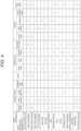
- Fig. 4 is a table exemplifying information that is stored in the visual recognition required point database according to this embodiment.
- Each row in the visual recognition required point database exemplified in Fig. 4 represents the travel environment in which the vehicle 1 travels ("STRAIGHT TRAVEL” in “STRAIGHT TRAVEL”, “CURVE”, and the like).
- each column in the visual recognition required point database exemplified in Fig. 4 represents the visual recognition required point to be visually recognized by the driver ("ADVANCING DIRECTION", "REAR-VIEW MIRROR”, and the like). Then, the visual recognition required point to be visually recognized by the driver in each of the travel environments is circled.
- the controller 10 identifies the travel environment of the vehicle 1 on the basis of the acquired travel environment information, and acquires the visual recognition required point in the identified travel environment from the visual recognition required point database.
- the visual recognition required points are identified as "ADVANCING DIRECTION”, “LEFT DOOR MIRROR”, “LEFT SIDE”, “PRECEDING VEHICLE”, “SIGNAL”, “END OF CROSSWALK”, “PEDESTRIAN”, and “TWO-WHEELED VEHICLE”.
- the controller 10 detects the driver's eye gaze on the basis of the signal received from the in-vehicle camera 32 (DETECT SIGHTLINE). Then, the controller 10 determines whether the driver has visually recognized the visual recognition required point on the basis of the identified visual recognition required point and the detected driver's eye gaze (DETERMINE VISUAL RECOGNITION). More specifically, in the case where the driver's sightline or eye gaze is directed within a specified range including the visual recognition required point (for example, in the case where an angle defined by a direction from the driver's head toward the visual recognition required point and the driver's eye gaze falls within five degrees), the controller 10 determines that the driver has visually recognized the visual recognition required point. This specified range is set and stored in the memory 10b or the like in advance.
- the controller 10 detects the driver's driving operation on the basis of the signals that are received from the sensors including the vehicle speed sensor 25, the acceleration sensor 26, the yaw rate sensor 27, the steering angle sensor 28, the steering torque sensor 29, the acceleration sensor 30, and the brake sensor 31 (DETECT DRIVING OPERATION).
- Examples of the driving operation are an accelerating operation, a decelerating operation, a left turn operation, and a right turn operation.
- the controller 10 determines whether the driver has visually recognized the visual recognition required point on the basis of the identified visual recognition required point as well as the detected driver's eye gaze and driving operation (DETERMINE VISUAL RECOGNITION). More specifically, in the case where the driver's eye gaze is directed within the specified range including the visual recognition required point (for example, in the case where the angle defined by the direction from the driver's head toward the visual recognition required point and the driver's eye gaze falls within 30 degrees), and the driving operation corresponding to the visual recognition required point is thereafter performed, the controller 10 determines that the driver has visually recognized the visual recognition required point. This specified range is set and stored in the memory 10b or the like in advance.
- driving operation corresponding to the visual recognition required point means the driving operation to be performed by the driver when the driver visually recognizes the visual recognition required point (for example, in the case where the visual recognition required point is a red light, the driving operation corresponding thereto is the decelerating operation), is set in advance for each of the visual recognition required points, and is stored in the memory 10b or the like.
- the controller 10 calculates a ratio (a missing ratio) of the number of the visual recognition required points that are not visually recognized by the driver to the total number of the visual recognition required points (CALCULATE MISSING RATIO).
- a specified threshold A for example, 40% or higher
- This threshold A is set and stored in the memory 10b or the like in advance.
- the controller 10 estimates the size of the effective visual field from the result of the visual recognition determination that is based on whether the driving operation corresponding to the visual recognition required point is performed when the driver's eye gaze is directed within the specified range including the visual recognition required point (ESTIMATE EFFECTIVE VISUAL FIELD). More specifically, the controller 10 acquires a minimum value (a minimum outside effective visual field angle) of the angles, each of which is defined by the direction from the driver's head toward the visual recognition required point and the driver's eye gaze, in regard to the visual recognition required points, each of which is determined not to be visually recognized by the driver.
- a minimum value a minimum outside effective visual field angle
- the controller 10 also acquires a maximum value (a maximum inside effective visual field angle) of the angles, each of which is defined by the direction from the driver's head toward the visual recognition required point and the driver's eye gaze, in regard to the visual recognition required points, each of which is determined to be visually recognized by the driver. Then, an intermediate value between the minimum outside effective visual field angle and the maximum inside effective visual field angle is defined as an effective visual field size (an effective viewing angle) Fv.
- a maximum inside effective visual field angle a maximum inside effective visual field angle
- a specified threshold B for example, smaller than five degrees
- This threshold B is set and stored in the memory 10b or the like in advance.
- the controller 10 When detecting the abnormality sign state, the controller 10 transmits, to the PCM 33, the DSC 34, and the EPS 35, the control signal for appropriately actuating the drive power source 2, the transmission 3, the brake 4, and the steering device 5, and transmits, to the display 36 and the speaker 37, the control signal for outputting the desired information.
- the controller 10 causes the display 36 to display the image information that is used to guide the driver's sightline or eye gaze to the visual recognition required point not visually recognized by the driver, and causes the speaker 37 to output the voice information.
- Fig. 5 is a flowchart of abnormality sign detection processing.
- the abnormality sign detection processing in Fig. 5 is initiated when a power supply of the vehicle 1 is turned on, and is repeatedly executed by the controller 10 at a specified time interval (for example, every 0.05 to 0.2 second).
- the controller 10 acquires the travel environment information on the basis of the signals that are received from the sensors including the outside camera 21, the radar 22, the navigation system 23, and the positioning system 24 (step S1).
- the controller 10 detects the driver's eye gaze on the basis of the signal that is received from the in-vehicle camera 32 (step S2). Then, the controller 10 identifies the visual recognition required point to be visually recognized by the driver on the basis of the travel environment information that is acquired in step S1, and determines whether the driver has visually recognized the visual recognition required point on the basis of the identified visual recognition required point and the driver's eye gaze that is detected in step S2 (step S3). As described above, in the case where the driver's sightline or eye gaze is directed within the specified range including the visual recognition required point, the controller 10 determines that the driver has visually recognized the visual recognition required point. In addition, in the case where the driver's eye gaze is directed within the specified range including the visual recognition required point, and thereafter the driving operation corresponding to the visual recognition required point is performed, the controller 10 determines that the driver has visually recognized the visual recognition required point.
- the controller 10 determines whether the driver is in the abnormal state on the basis of the signals that are received from the sensors including the outside camera 21, the radar 22, the navigation system 23, the positioning system 24, the vehicle speed sensor 25, the acceleration sensor 26, the yaw rate sensor 27, the steering angle sensor 28, the steering torque sensor 29, the acceleration sensor 30, the brake sensor 31, and the in-vehicle camera 32 (step S4).
- the controller 10 detects an amplitude and a frequency of the vehicle driver's saccade, detects such an attention level that is increased as the number of caution points to be checked by the driver during the travel is increased in the external environment of the vehicle, and determines whether the driver is in the abnormal state on the basis of the attention level and the amplitude and the frequency of the driver's saccade.
- the controller 10 detects the driver's sightline or gaze direction, a posture (a position of an upper body or the head), opening amounts of the driver's eye lids, the driver's steering wheel grip force, or the like.
- the controller 10 can also determine that the driver is in the abnormal state. For example, in the case where stability of the eye gaze direction is lower than a specified value, in the case where stability of the posture is lower than a specified value, in the case where the eye lids keep closed for a specified time or longer, or in the case where the steering wheel grip force is smaller than a specified value, the controller 10 can determine that the driver is in the abnormal state. In addition, for example, in the case where stability of the position of the vehicle 1 from a center line on the travel road, stability of the steering angle, or the like is lower than a specified value, the controller 10 can estimate that the driver is in the abnormal state.
- step S4 YES
- the controller 10 transmits the control signal to the display 36 and the speaker 37 and causes the display 36 and the speaker 37 to output a warning.
- the controller 10 also transmits, to the PCM 33, the DSC 34, and the EPS 35, the control signal to appropriately actuate the drive power source 2, the transmission 3, the brake 4, and the steering device 5, and thereby controls the behavior of the vehicle 1 such that the vehicle 1 is safely stopped on a road shoulder, for example (step S5).
- step S5 the controller 10 terminates the abnormality sign detection processing.
- step S4 determines that the driver is not in the abnormal state (step S4: NO)
- the controller 10 calculates the missing ratio Fr from the result of the visual recognition determination that is based on whether the driver's eye gaze is directed within the specified range including the visual recognition required point (step S6).
- step S7 determines whether the missing ratio Fr calculated in step S6 is equal to or higher than the specified threshold A. As a result, if the missing ratio Fr is equal to or higher than the specified threshold A (step S7: YES), the controller 10 determines that the driver is in the abnormality sign state. That is, the driver's abnormality sign state is detected (step S8).
- the controller 10 transmits the control signal to the display 36 and the speaker 37, and causes the display 36 and the speaker 37 to respectively output the image information and the voice information (sightline guidance information) that are used to guide the driver's eye gaze to the visual recognition required point not visually recognized by the driver (step S9).
- the controller 10 terminates the abnormality sign detection processing.
- step S7 if the missing ratio Fr is not equal to or higher than the specified threshold A (is lower than the threshold A) (step S7: NO), the controller 10 estimates the effective visual field size Fv from the result of the visual recognition determination in step S3 that is based on whether the driving operation corresponding to the visual recognition required point is performed when the driver's sightline or eye gaze is directed within the specified range including the visual recognition required point (step S10).
- step S11 determines whether the effective visual field size Fv estimated in step S10 is smaller than the specified threshold B (step S11). As a result, if the effective visual field size Fv is smaller than the specified threshold B (step S11: YES), the controller 10 determines that the driver is in the abnormality sign state. That is, the driver's abnormality sign state is detected (step S8). In this case, the controller 10 causes the display 36 and the speaker 37 to output the sightline guidance information (step S9), and terminates the abnormality sign detection processing.
- step S11 if the effective visual field size Fv is not smaller than the specified threshold B (is equal to or larger than the threshold B) (step S11: NO), the controller 10 determines that the driver is not in the abnormality sign state. That is, the driver's abnormality sign state is not detected (step S12). After step S12, the controller 10 terminates the abnormality sign detection processing.
- the controller 10 detects the driver's abnormality sign state on the basis of each of whether the missing ratio Fr is equal to or higher than the specified threshold A and whether the effective visual field size Fv is smaller than the specified threshold B.
- the controller 10 may detect the abnormality sign state on the basis of only one of the missing ratio Fr and the effective visual field size Fv.
- the controller 10 detects the driver's abnormality sign state when determining in step S4 that the driver is not in the abnormal state (step S4: NO). However, the determination on whether the driver is in the abnormal state may not be made, or the determination on whether the driver is in the abnormal state may be made after the abnormality sign state is detected.
- the effective visual field size Fv is estimated from the result of the visual recognition determination that is based on whether the driving operation corresponding to the visual recognition required point is performed when the driver's eye gaze is directed within the specified range including the visual recognition required point.
- the effective visual field size may be estimated by a different method therefrom.
- the effective visual field size can also be estimated on the basis of an angle that is defined by a direction from the driver's head toward the object with high saliency (for example, the object with a significant color difference or luminance difference from the surrounding area, or the object with large motion with respective to the surroundings) and the driver's eye gaze at the time when the driver's eye gaze is directed to such an object.
- the controller 10 identifies the visual recognition required point to be visually recognized by the driver on the basis of the travel environment information, determines whether the driver has visually recognized the visual recognition required point on the basis of the driver's eye gaze, and detects the driver's abnormality sign state on the basis of the fact that the driver has not visually recognized the visual recognition required point.
- the abnormality sign state by using the fact that the driver has not been able to visually recognize the visual recognition required point due to the decline in the distributive attention function or a reduction in the effective visual field at the initial stage of the decline in the driver's attention function.
- the controller 10 determines that the driver has visually recognized the visual recognition required point in the case where the driver's eye gaze is directed within the specified range including the visual recognition required point, and detects the driver's abnormality sign state on the basis of the number of the visual recognition required points not visually recognized by the driver. Accordingly, when the driver can no longer visually recognize the plural visual recognition required points at the same time due to the decline in the distributive attention function and starts missing the visual recognition required points at the initial stage of the decline in the attention function, the abnormality sign state can be detected on the basis of the severity of missing of the visual recognition required point. In this way, it is possible to appropriately detect the driver's abnormality sign state at the stage sufficiently earlier than onset of the abnormal state where the driver has difficulty in driving.
- the controller 10 is configured to detect the driver's abnormality sign state in the case where the missing ratio of the visual recognition required point is equal to or higher than the specified value. Accordingly, when the driver can no longer visually recognize the plural visual recognition required points at the same time due to the decline in the distributive attention function and the missing ratio of the visual recognition required point becomes equal to or higher than the specified value at the initial stage of the decline in the attention function, the abnormality sign state can be detected. In this way, it is possible to appropriately detect the driver's abnormality sign state at the stage sufficiently earlier than the onset of the abnormal state where the driver has difficulty in driving.
- the controller 10 estimates the effective visual field size that can be visually recognized by the driver on the basis of the distance between the driver's eye gaze and the visual recognition required point not visually recognized by the driver. Then, in the case where the estimated effective visual field size is smaller than the specified value, the driver's abnormality sign state is detected. Accordingly, when the effective visual field is narrowed and the driver starts missing the visual recognition required point at the initial stage of the decline in the attention function, the abnormality sign state can be detected by estimating the degree of the narrowness of the effective visual field. In this way, it is possible to appropriately detect the driver's abnormality sign state at the stage sufficiently earlier than the onset of the abnormal state where the driver has difficulty in driving.
- the driver abnormality sign detection apparatus 100 further includes the display 36 and the speaker 37, each of which outputs the information to the driver.
- the controller 10 causes the display 36 and the speaker 37 to output the information to guide the driver's sightline or eye gaze to the visual recognition required point. Accordingly, in the case where the driver's abnormality sign state is detected, the driver's eye gaze can be guided to the visual recognition required point. Therefore, it is possible to provide the appropriate driver assistance to the driver who starts missing the visual recognition required point at the initial stage of the decline in the attention function.
Landscapes
- Engineering & Computer Science (AREA)
- Health & Medical Sciences (AREA)
- Life Sciences & Earth Sciences (AREA)
- Automation & Control Theory (AREA)
- Physics & Mathematics (AREA)
- Transportation (AREA)
- Mechanical Engineering (AREA)
- Mathematical Physics (AREA)
- Public Health (AREA)
- Molecular Biology (AREA)
- Veterinary Medicine (AREA)
- General Health & Medical Sciences (AREA)
- Animal Behavior & Ethology (AREA)
- Surgery (AREA)
- Biophysics (AREA)
- Pathology (AREA)
- Biomedical Technology (AREA)
- Heart & Thoracic Surgery (AREA)
- Medical Informatics (AREA)
- Human Computer Interaction (AREA)
- Developmental Disabilities (AREA)
- Hospice & Palliative Care (AREA)
- Educational Technology (AREA)
- Social Psychology (AREA)
- Child & Adolescent Psychology (AREA)
- Psychology (AREA)
- Psychiatry (AREA)
- General Physics & Mathematics (AREA)
- Multimedia (AREA)
- Theoretical Computer Science (AREA)
- Traffic Control Systems (AREA)
- Control Of Driving Devices And Active Controlling Of Vehicle (AREA)
Abstract
Description
- The present invention relates to a driver abnormality sign detection apparatus for detecting an abnormality sign state of a driver during driving of a vehicle.
- Conventionally, a driver state detection apparatus that detects an abnormal state of a driver of a vehicle has been proposed (for example, see Patent document 1). In the apparatus disclosed in Patent document 1, an amplitude and a frequency of the vehicle driver's saccade (jumping eye motion of the driver to intentionally move his/her eye gaze) are detected, and such an attention level is detected that is increased as the number of caution points to be checked by the driver during travel is increased in vehicle outside environment, so as to detect the abnormality of the driver on the basis of the attention level and the amplitude and the frequency of the driver's saccade.
- [Patent document 1]
JP-A-2021-077136 - However, in a state where the driver's attention function is slightly declined due to a mild disease, aging, or the like but the driver can still drive, that is, an abnormality sign state which typically occurs prior to an abnormal state where the driver has difficulty in driving, no obvious difference appears to the amplitude and the frequency of the driver's saccade in comparison with a state with no abnormality. Thus, the abnormality sign state cannot be detected by the related art as described above.
- The invention has been made to solve such a problem and therefore has a purpose of providing a driver abnormality sign detection apparatus capable of detecting an abnormality sign state of a driver at a stage sufficiently earlier than onset of an abnormal state where the driver has difficulty in driving.
- In order to solve the above-described problem, the invention is a driver abnormality sign detection apparatus that detects an abnormality sign state of a driver who drives a vehicle, and includes: a travel environment information acquisition device that acquires travel environment information of the vehicle; an eye gaze tracker (to which is sometimes referred to as sightline detector) that detects the driver's eye gaze; and a controller configured to detect the driver's abnormality sign state on the basis of the travel environment information and the driver's eye gaze (to which is sometimes referred to as driver's sightline). The controller is configured to: identify a visual recognition required point to be visually recognized by the driver on the basis of the travel environment information; determine whether the driver has visually recognized the visual recognition required point on the basis of the driver's eye gaze; and detect the driver's abnormality sign state on the basis of a fact that the driver has not visually recognized the visual recognition required point.
- According to the present invention that is configured as described above, the controller identifies the visual recognition required point to be visually recognized by the driver on the basis of the travel environment information, determines whether the driver has visually recognized the visual recognition required point on the basis of the the driver's eye gaze, and detects the driver's abnormality sign state on the basis of the fact that the driver has not visually recognized the visual recognition required point. Thus, it is possible to detect the abnormality sign state by using a fact that the driver has not been able to visually recognize the visual recognition required point due to a decline in a distributive attention function or a reduction in an effective visual field at an initial stage of a decline in the driver's attention function. In this way, it is possible to detect the driver's abnormality sign state at a stage, at which no obvious difference appears to the amplitude and the frequency of the driver's saccade and which is sufficiently earlier than onset of the abnormal state where the driver has difficulty in driving, for example.
- In the invention, preferably, the controller is configured to: determine that the driver has visually recognized the visual recognition required point in the case where the driver's eye gaze is directed within a specified range including the visual recognition required point; and, preferably, detect the driver's abnormality sign state on the basis of the number of the visual recognition required point not visually recognized by the driver.
- According to the invention that is configured as described above, the driver's abnormality sign state is detected on the basis of the number of the visual recognition required point to which the driver's eye gaze is not directed. Thus, when the driver can no longer visually recognize the plural visual recognition required points at the same time due to the decline in the distributive attention function and starts missing the visual recognition required points at the initial stage of the decline in the attention function, the abnormality sign state can be detected on the basis of the severity of missing of the visual recognition required point. In this way, it is possible to appropriately detect the driver's abnormality sign state at the stage sufficiently earlier than the onset of the abnormal state where the driver has difficulty in driving.
- In the invention, preferably, the controller is configured to detect the driver's abnormality sign state in the case where a ratio of the number of the visual recognition required point not visually recognized by the driver to the total number of the visual recognition required points is equal to or larger than a specified value.
- According to the invention that is configured as described above, when the driver can no longer visually recognize the plural visual recognition required points at the same time due to the decline in the distributive attention function and the missing ratio of the visual recognition required point becomes equal to or higher than the specified value at the initial stage of the decline in the attention function, the abnormality sign state can be detected. In this way, it is possible to appropriately detect the driver's abnormality sign state at the stage sufficiently earlier than the onset of the abnormal state where the driver has difficulty in driving.
- In the invention, preferably, the controller is configured to: estimate a size of an effective visual field that can be visually recognized by the driver on the basis of a distance between the driver's sightline or the driver's eye gaze and the visual recognition required point not visually recognized by the driver; and detect the driver's abnormality sign state in the case where the estimated effective visual field size is smaller than the specified value.
- According to the invention that is configured as described above, when the effective visual field is narrowed and the driver starts missing the visual recognition required point at the initial stage of the decline in the attention function, the abnormality sign state can be detected by estimating the degree of the narrowness of the effective visual field. In this way, it is possible to appropriately detect the driver's abnormality sign state at the stage sufficiently earlier than the onset of the abnormal state where the driver has difficulty in driving.
- In the invention, preferably, the controller is configured to estimate the size of the effective visual field by comparing a minimum value of the angles of the driver's head with respect to at least one visual recognition required point that has not been visually recognized and the driver's eye gaze with a maximum value of the angles of the driver's head with respect to at least one visual recognition required point that has been visually recognized and the driver's eye gaze.
- The invention, preferably, the controller is configured to estimate the size of the effective visual field by being an intermediate value, preferably a mean value, between the minimum value of the angles of the driver's head with respect to at least one visual recognition required point that has not been visually recognized and the driver's eye gaze and the maximum value of the angles of the driver's head with respect to at least one visual recognition required point that has been visually recognized and the driver's eye gaze.
- In the invention, preferably, the driver abnormality sign detection apparatus further includes an information output device that outputs information to the driver. The controller is configured to cause the information output device to output information that is used to guide the driver's eye gaze to the visual recognition required point in the case where the driver's abnormality sign state is detected.
- According to the invention that is configured as described above, in the case where the driver's abnormality sign state is detected, the driver's eye gaze is guided to the visual recognition required point. Therefore, it is possible to provide the appropriate driver assistance to the driver who starts missing the visual recognition required point at the initial stage of the decline in the attention function.
- In the invention, preferably, the travel environment information acquisition device (21-24) for acquiring travel environment information of the vehicle (1) comprises at least one of: an outside camera (21) for capturing an image around the vehicle (1), a radar (22) for measuring a position and a speed of an object with respect to the vehicle (1), a navigation system (23) for providing map information to the controller (10), and a speed sensor for detecting a speed of the vehicle (1).
- In the invention, preferably, the eye gaze tracker comprises an in-vehicle camera for capturing an image of the driver of the vehicle (1).
- In the invention, preferably, the driver abnormality sign detection apparatus further comprises:
- a driving operation detector (25-31) for detecting a driving operation of the vehicle (1) caused by the driver, wherein
- the controller (10) is adapted to determine that the driver has visually recognized the visual recognition required point, in the case where the driver's eye gaze is directed within a specified range including the visual recognition required point, and, thereafter, the driving operation performed by the driver of the vehicle corresponds to the visual recognition required point.
- In the invention, preferably, the controller (10) is adapted to determine that the driver has not visually recognized the visual recognition required point, in the case where the driver's eye gaze is directed within a specified range including the visual recognition required point, and, thereafter, the driving operation performed by the driver of the vehicle fails to correspond to the visual recognition required point.
- In the invention, preferably, the driving operation detector (25-31) comprises at least one of: a vehicle speed sensor (25) for detecting a speed of the vehicle (1), a yaw rate sensor (27) for detecting a yaw rate of the vehicle (1), a steering angle sensor (28) for detecting a rotation angle of a steering wheel (5), a steering torque sensor (29) for detecting torque applied to a steering shaft via a steering wheel (5), an acceleration sensor (26, 30) for detecting an depression amount of an accelerator pedal, and a brake sensor (31) for detecting a depression amount of a brake pedal.
- In the invention, preferably, the visual recognition required point is a red light or a stop sign, the driving operation corresponding thereto is the decelerating operation.
- In the invention, preferably, the driver abnormality sign detection apparatus further comprises a visual recognition required point database in which the travel environment and the visual recognition required points are stored in a mutually corresponding manner, for identifying the visual recognition required points to be visually recognized by the driver on basis of the current travel environment detected by the travel environment information acquisition device.
- The invention is further directed to a vehicle comprising the driver abnormality sign detection apparatus according to the invention.
- According to the driver abnormality sign detection apparatus of the invention, the driver's abnormality sign state can be detected at the stage sufficiently earlier than the abnormal state where the driver has difficulty in driving.
-
- [
Fig. 1] Fig. 1 is an explanatory view of a vehicle on which a driver abnormality sign detection apparatus according to an embodiment of the invention is mounted. - [
Fig. 2] Fig. 2 is a block diagram of the driver abnormality sign detection apparatus according to the embodiment of the invention. - [
Fig. 3] Fig. 3 is a control block diagram of abnormality sign detection according to the embodiment of the invention. - [
Fig. 4] Fig. 4 is a table exemplifying information that is stored in a visual recognition required point database according to the embodiment of the invention. - [
Fig. 5] Fig. 5 is a flowchart of detection processing of an abnormality sign state according to the embodiment of the invention. - A description will hereinafter be made on a driver abnormality sign detection apparatus according to an embodiment of the invention with reference to the accompanying drawings.
- First, a description will be made on a configuration of the driver abnormality sign detection apparatus according to this embodiment with reference to
Fig. 1 andFig. 2 .Fig. 1 is an explanatory view of a vehicle on which the driver abnormality sign detection apparatus is mounted, andFig. 2 is a block diagram of the driver abnormality sign detection apparatus. - A vehicle 1 according to this embodiment includes: drive
power sources 2 such as an engine and an electric motor that output drive power; atransmission 3 that transmits the drive power output from thedrive power source 2 to drive wheels; a brake 4 that applies a braking force to the vehicle 1; and asteering device 5 for steering the vehicle 1. - A driver abnormality
sign detection apparatus 100 is configured to detect an abnormality sign state of a driver of the vehicle 1 and to execute control of the vehicle 1 and driving assistance control when necessary. As illustrated inFig. 2 , the driver abnormalitysign detection apparatus 100 has acontroller 10, plural sensors, plural control systems, and plural information output devices. - More specifically, the plural sensors include an
outside camera 21 and aradar 22 for acquiring travel environment information of the vehicle 1 as well as anavigation system 23 and apositioning system 24 for detecting a position of the vehicle 1. The plural sensors also include avehicle speed sensor 25, anacceleration sensor 26, ayaw rate sensor 27, asteering angle sensor 28, asteering torque sensor 29, anacceleration sensor 30, and abrake sensor 31 for detecting behavior of the vehicle 1 and the driver's driving operation. The plural sensors further include an in-vehicle camera 32 for detecting the driver's eye gaze. The plural control systems include: a powertrain control module (PCM) 33 that controls thedrive power source 2 and thetransmission 3; a dynamic stability control system (DSC) 34 that controls thedrive power source 2 and the brake 4; and an electric power steering system (EPS) 35 that controls thesteering device 5. The plural information output devices include adisplay 36 that outputs image information and aspeaker 37 that outputs voice information. - In addition, other sensors may include a peripheral sonar that measures a distance and a position of a peripheral structure relative to the vehicle 1, a corner radar that measures approach of the peripheral structure to four corner sections of the vehicle 1, and various sensors (a heart rate sensor, an electrocardiogram sensor, a steering wheel grip force sensor, and the like) that detect the driver's state.
- The
controller 10 executes various arithmetic operations on the basis of signals received from the plural sensors, transmits, to thePCM 33, theDSC 34, and theEPS 35, a control signal for appropriately actuating thedrive power source 2, thetransmission 3, the brake 4, and thesteering device 5, and transmits, to thedisplay 36 and thespeaker 37, a control signal for outputting desired information. Thecontroller 10 is a computer that includes one ormore processors 10a (typically, a CPU),memory 10b (ROM, RAM, and the like) that stores various programs and data, an input/output device, and the like. - The
outside camera 21 captures an image around the vehicle 1 and outputs image data. Thecontroller 10 identifies an object (a preceding vehicle, a parked vehicle, a pedestrian, a travel road, a lane marking (a lane divider, a white line, or a yellow line), a traffic signal, a traffic sign, a stop line, an intersection, an obstacle, or the like) on the basis of the image data received from theoutside camera 21. Theoutside camera 21 corresponds to an example of the "travel environment information acquisition device" in the invention. - The
radar 22 measures a position and a speed of the object (particularly, the preceding vehicle, the parked vehicle, the pedestrian, a dropped object on the travel road, or the like). For example, a millimeter-wave radar can be used as theradar 22. Theradar 22 transmits a radio wave in an advancing direction of the vehicle 1, and receives a reflected wave that is generated when the object reflects the transmitted wave. Then, based on the transmitted wave and the received wave, theradar 22 measures a distance between the vehicle 1 and the object (for example, an inter-vehicular distance) and a relative speed of the object to the vehicle 1. In this embodiment, instead of theradar 22, a laser radar, an ultrasonic sensor, or the like may be used to measure the distance from and the relative speed of the object. Alternatively, the plural sensors may be used to constitute a position and speed measuring device. Theradar 22 corresponds to an example of the "travel environment information acquisition device" in the invention. - The
navigation system 23 stores map information therein and can provide the map information to thecontroller 10. Based on the map information and current vehicle position information, thecontroller 10 identifies a road, the intersection, the traffic signal, a building, or the like that exists around (particularly, in the advancing direction of) the vehicle 1. The map information may be stored in thecontroller 10. Thepositioning system 24 is a GPS system and/or a gyroscopic system, and detects the position of the vehicle 1 (the current vehicle position information). Each of thenavigation system 23 and thepositioning system 24 also corresponds to an example of the "travel environment information acquisition device" in the invention. - The
vehicle speed sensor 25 detects a speed of the vehicle 1 on the basis of a rotational speed of the wheel or a driveshaft, for example. Theacceleration sensor 26 detects acceleration of the vehicle 1. This acceleration includes acceleration in a front-rear direction of the vehicle 1 and acceleration in a lateral direction (that is, lateral acceleration) thereof. In the present specification, the acceleration includes not only a change rate of the speed in a speed increasing direction but also a change rate of the speed in a speed reducing direction (that is, deceleration). - The
yaw rate sensor 27 detects a yaw rate of the vehicle 1. Thesteering angle sensor 28 detects a rotation angle (a steering angle) of a steering wheel of thesteering device 5. Thesteering torque sensor 29 detects torque (steering torque) applied to a steering shaft via the steering wheel. Theacceleration sensor 30 detects a depression amount of an accelerator pedal. Thebrake sensor 31 detects a depression amount of a brake pedal. - The in-
vehicle camera 32 captures an image of the driver and outputs image data. Thecontroller 10 detects the driver's eye gaze direction on the basis of the image data that is received from the in-vehicle camera 32. The in-vehicle camera 32 corresponds to an example of the " eye gaze tracker" (to which is sometimes referred to as sightline detector) in the invention. - The
PCM 33 controls thedrive power source 2 of the vehicle 1 to adjust the drive power of the vehicle 1. For example, thePCM 33 controls an ignition plug of the engine, a fuel injection valve, a throttle valve, a variable valve mechanism, thetransmission 3, an inverter that supplies electric power to the electric motor, and the like. When the vehicle 1 has to be accelerated or decelerated, thecontroller 10 transmits the control signal to thePCM 33 so as to adjust the drive power. - The
DSC 34 controls thedrive power source 2 and the brake 4 of the vehicle 1 and thereby executes deceleration control and posture control of the vehicle 1. For example, theDSC 34 controls a hydraulic pump, a valve unit, and the like of the brake 4, and controls thedrive power source 2 via thePCM 33. When it is necessary to execute the deceleration control or the posture control of the vehicle 1, thecontroller 10 transmits the control signal to theDSC 34 so as to adjust the drive power or generate the braking force. - The
EPS 35 controls thesteering device 5 of the vehicle 1. For example, theEPS 35 controls the electric motor, which applies the torque to the steering shaft of thesteering device 5, and the like. When the advancing direction of the vehicle 1 has to be changed, thecontroller 10 transmits the control signal to theEPS 35 so as to change a steering direction. - The
display 36 is provided in front of the driver in a cabin and displays the image information to the driver. As thedisplay 36, for example, a liquid-crystal display or a head-up display is used. Thespeaker 37 is installed in the cabin and outputs various types of the voice information. - Next, a description will be made on a basic concept of driver abnormality sign detection that is executed by the above-described
controller 10 in this embodiment with reference toFig. 3. Fig. 3 is a control block diagram of the abnormality sign detection according to this embodiment. - In the abnormality sign state prior to an abnormal state where the driver has difficulty in driving, it is considered that the driver's attention function starts being declined due to a mild disease, aging, or the like. In view of the above, the present inventors considered that the abnormality sign state could be detected by detecting this decline in the driver's attention function.
- The driver's attention function mainly includes: a function to see plural objects simultaneously (a distributive attention function); a function to select the object from the plural objects and see the selected object (a selective attention function); a function to switch the object (a shifting attention function); and a function to keep seeing the object (a continuous attention function). A result of research by the present inventors has led to such a finding that, in the case where the attention function is declined due to a certain disease (a cardiac disorder, a brain disorder, hypoglycemia, or the like) or aging, the attention function is declined in an order of the distributive attention function → the selective attention function → the shifting attention function → the continuous attention function. That is, at an initial stage of the decline in the attention function, plural visual recognition required points that should be recognized visually (recognized by seeing with eyes) by the driver during driving can no longer be visually recognized at the same time, and the driver begins to miss some of the visual recognition required points due to the decline in the distributive attention function. Thus, the abnormality sign state can be detected on the basis of severity of missing of the visual recognition required point.
- The result of the research by the present inventors has also led to such a finding that, a patient whose attention function is declined has a narrow effective visual field (of the entire visual field, a range where information can be acquired effectively) and thus cannot visually recognize the object even when his/her eye gaze is directed to vicinity of the object. That is, at the initial stage of the decline in the attention function, since the effective visual field is narrowed, it becomes difficult to visually recognize the visual recognition required point, and consequently, the visual recognition required point is missed. Thus, the abnormality sign state can be detected by estimating a degree of narrowness of the effective visual field from a distance between the visual recognition required point and the sightline or eye gaze at the time when the visual recognition required point cannot be recognized visually.
- Accordingly, the
controller 10 in this embodiment is configured to identify the visual recognition required point on the basis of the travel environment information, determines whether the driver has visually recognized the visual recognition required point on the basis of the driver's sightline or the driver's eye gaze, and identifies the severity of missing of the visual recognition required point and a size of the effective visual field on the basis of a fact that the driver has not visually recognized the visual recognition required point, so as to detect the driver's abnormality sign state. - More specifically, as illustrated in
Fig. 3 , thecontroller 10 acquires the travel environment information on the basis of the signals that are received from the sensors including theoutside camera 21, theradar 22, thenavigation system 23, and the positioning system 24 (ACQUIRE TRAVEL ENVIRONMENT INFORMATION). The travel environment information is information on environment in which the vehicle 1 travels. Examples of the travel environment information are: type information and positional information of the object, such as the preceding vehicle, the parked vehicle, the pedestrian, the travel road, the lane marking (the lane divider, the white line, or the yellow line), the traffic signal, the traffic sign, the stop line, the intersection, or the obstacle, that exists around the vehicle 1; information on a type and a shape of the road on which the vehicle 1 travels; information on the peripheral building; and information on a current position of the vehicle 1. - Based on the acquired travel environment information, the
controller 10 refers to a visual recognition required point database in which the travel environment and the visual recognition required points are stored in a mutually corresponding manner, and identifies the visual recognition required point to be visually recognized by the driver (IDENTIFY VISUAL RECOGNITION REQUIRED POINT). The visual recognition required point database is stored in thememory 10b or the like in advance. -
Fig. 4 is a table exemplifying information that is stored in the visual recognition required point database according to this embodiment. Each row in the visual recognition required point database exemplified inFig. 4 represents the travel environment in which the vehicle 1 travels ("STRAIGHT TRAVEL" in "STRAIGHT TRAVEL", "CURVE", and the like). Meanwhile, each column in the visual recognition required point database exemplified inFig. 4 represents the visual recognition required point to be visually recognized by the driver ("ADVANCING DIRECTION", "REAR-VIEW MIRROR", and the like). Then, the visual recognition required point to be visually recognized by the driver in each of the travel environments is circled. Thecontroller 10 identifies the travel environment of the vehicle 1 on the basis of the acquired travel environment information, and acquires the visual recognition required point in the identified travel environment from the visual recognition required point database. For example, in the case where the travel environment is "LEFT TURN" under "INTERSECTION", in the example illustrated inFig. 4 , the visual recognition required points are identified as "ADVANCING DIRECTION", "LEFT DOOR MIRROR", "LEFT SIDE", "PRECEDING VEHICLE", "SIGNAL", "END OF CROSSWALK", "PEDESTRIAN", and "TWO-WHEELED VEHICLE". - The
controller 10 detects the driver's eye gaze on the basis of the signal received from the in-vehicle camera 32 (DETECT SIGHTLINE). Then, thecontroller 10 determines whether the driver has visually recognized the visual recognition required point on the basis of the identified visual recognition required point and the detected driver's eye gaze (DETERMINE VISUAL RECOGNITION). More specifically, in the case where the driver's sightline or eye gaze is directed within a specified range including the visual recognition required point (for example, in the case where an angle defined by a direction from the driver's head toward the visual recognition required point and the driver's eye gaze falls within five degrees), thecontroller 10 determines that the driver has visually recognized the visual recognition required point. This specified range is set and stored in thememory 10b or the like in advance. - The
controller 10 detects the driver's driving operation on the basis of the signals that are received from the sensors including thevehicle speed sensor 25, theacceleration sensor 26, theyaw rate sensor 27, thesteering angle sensor 28, thesteering torque sensor 29, theacceleration sensor 30, and the brake sensor 31 (DETECT DRIVING OPERATION). Examples of the driving operation are an accelerating operation, a decelerating operation, a left turn operation, and a right turn operation. - Then, the
controller 10 determines whether the driver has visually recognized the visual recognition required point on the basis of the identified visual recognition required point as well as the detected driver's eye gaze and driving operation (DETERMINE VISUAL RECOGNITION). More specifically, in the case where the driver's eye gaze is directed within the specified range including the visual recognition required point (for example, in the case where the angle defined by the direction from the driver's head toward the visual recognition required point and the driver's eye gaze falls within 30 degrees), and the driving operation corresponding to the visual recognition required point is thereafter performed, thecontroller 10 determines that the driver has visually recognized the visual recognition required point. This specified range is set and stored in thememory 10b or the like in advance. Here, "driving operation corresponding to the visual recognition required point" means the driving operation to be performed by the driver when the driver visually recognizes the visual recognition required point (for example, in the case where the visual recognition required point is a red light, the driving operation corresponding thereto is the decelerating operation), is set in advance for each of the visual recognition required points, and is stored in thememory 10b or the like. - From a result of the visual recognition determination that is based on whether the driver's sightline or eye gaze is directed within the specified range including the visual recognition required point, the
controller 10 calculates a ratio (a missing ratio) of the number of the visual recognition required points that are not visually recognized by the driver to the total number of the visual recognition required points (CALCULATE MISSING RATIO). In other words, a missing ratio Fr can be calculated by the following equation.
- Then, when the missing ratio Fr is equal to or higher than a specified threshold A (for example, 40% or higher), it is determined that the driver is in the abnormality sign state. That is, the driver's abnormality sign state is detected (DETECT ABNORMALITY SIGN). This threshold A is set and stored in the
memory 10b or the like in advance. - The
controller 10 estimates the size of the effective visual field from the result of the visual recognition determination that is based on whether the driving operation corresponding to the visual recognition required point is performed when the driver's eye gaze is directed within the specified range including the visual recognition required point (ESTIMATE EFFECTIVE VISUAL FIELD). More specifically, thecontroller 10 acquires a minimum value (a minimum outside effective visual field angle) of the angles, each of which is defined by the direction from the driver's head toward the visual recognition required point and the driver's eye gaze, in regard to the visual recognition required points, each of which is determined not to be visually recognized by the driver. Thecontroller 10 also acquires a maximum value (a maximum inside effective visual field angle) of the angles, each of which is defined by the direction from the driver's head toward the visual recognition required point and the driver's eye gaze, in regard to the visual recognition required points, each of which is determined to be visually recognized by the driver. Then, an intermediate value between the minimum outside effective visual field angle and the maximum inside effective visual field angle is defined as an effective visual field size (an effective viewing angle) Fv. - Then, when the effective visual field size Fv is smaller than a specified threshold B (for example, smaller than five degrees), it is determined that the driver is in the abnormality sign state. That is, the driver's abnormality sign state is detected (DETECT ABNORMALITY SIGN). This threshold B is set and stored in the
memory 10b or the like in advance. - When detecting the abnormality sign state, the
controller 10 transmits, to thePCM 33, theDSC 34, and theEPS 35, the control signal for appropriately actuating thedrive power source 2, thetransmission 3, the brake 4, and thesteering device 5, and transmits, to thedisplay 36 and thespeaker 37, the control signal for outputting the desired information. For example, thecontroller 10 causes thedisplay 36 to display the image information that is used to guide the driver's sightline or eye gaze to the visual recognition required point not visually recognized by the driver, and causes thespeaker 37 to output the voice information. - Next, a description will be made on a flow of detection processing of the abnormality sign state by the driver abnormality
sign detection apparatus 100 in this embodiment with reference toFig. 5. Fig. 5 is a flowchart of abnormality sign detection processing. - The abnormality sign detection processing in
Fig. 5 is initiated when a power supply of the vehicle 1 is turned on, and is repeatedly executed by thecontroller 10 at a specified time interval (for example, every 0.05 to 0.2 second). - When the abnormality sign detection processing is initiated, first, the
controller 10 acquires the travel environment information on the basis of the signals that are received from the sensors including theoutside camera 21, theradar 22, thenavigation system 23, and the positioning system 24 (step S1). - In addition, the
controller 10 detects the driver's eye gaze on the basis of the signal that is received from the in-vehicle camera 32 (step S2). Then, thecontroller 10 identifies the visual recognition required point to be visually recognized by the driver on the basis of the travel environment information that is acquired in step S1, and determines whether the driver has visually recognized the visual recognition required point on the basis of the identified visual recognition required point and the driver's eye gaze that is detected in step S2 (step S3). As described above, in the case where the driver's sightline or eye gaze is directed within the specified range including the visual recognition required point, thecontroller 10 determines that the driver has visually recognized the visual recognition required point. In addition, in the case where the driver's eye gaze is directed within the specified range including the visual recognition required point, and thereafter the driving operation corresponding to the visual recognition required point is performed, thecontroller 10 determines that the driver has visually recognized the visual recognition required point. - Next, the
controller 10 determines whether the driver is in the abnormal state on the basis of the signals that are received from the sensors including theoutside camera 21, theradar 22, thenavigation system 23, thepositioning system 24, thevehicle speed sensor 25, theacceleration sensor 26, theyaw rate sensor 27, thesteering angle sensor 28, thesteering torque sensor 29, theacceleration sensor 30, thebrake sensor 31, and the in-vehicle camera 32 (step S4). - For example, as in the technique disclosed in
JP-A-2021-077136 controller 10 detects an amplitude and a frequency of the vehicle driver's saccade, detects such an attention level that is increased as the number of caution points to be checked by the driver during the travel is increased in the external environment of the vehicle, and determines whether the driver is in the abnormal state on the basis of the attention level and the amplitude and the frequency of the driver's saccade. Alternatively, thecontroller 10 detects the driver's sightline or gaze direction, a posture (a position of an upper body or the head), opening amounts of the driver's eye lids, the driver's steering wheel grip force, or the like. In this way, based on such a detection result, thecontroller 10 can also determine that the driver is in the abnormal state. For example, in the case where stability of the eye gaze direction is lower than a specified value, in the case where stability of the posture is lower than a specified value, in the case where the eye lids keep closed for a specified time or longer, or in the case where the steering wheel grip force is smaller than a specified value, thecontroller 10 can determine that the driver is in the abnormal state. In addition, for example, in the case where stability of the position of the vehicle 1 from a center line on the travel road, stability of the steering angle, or the like is lower than a specified value, thecontroller 10 can estimate that the driver is in the abnormal state. - As a result, if it is determined that the driver is in the abnormal state (step S4: YES), the
controller 10 transmits the control signal to thedisplay 36 and thespeaker 37 and causes thedisplay 36 and thespeaker 37 to output a warning. Thecontroller 10 also transmits, to thePCM 33, theDSC 34, and theEPS 35, the control signal to appropriately actuate thedrive power source 2, thetransmission 3, the brake 4, and thesteering device 5, and thereby controls the behavior of the vehicle 1 such that the vehicle 1 is safely stopped on a road shoulder, for example (step S5). After step S5, thecontroller 10 terminates the abnormality sign detection processing. - On the other hand, if it is determined that the driver is not in the abnormal state (step S4: NO), the
controller 10 calculates the missing ratio Fr from the result of the visual recognition determination that is based on whether the driver's eye gaze is directed within the specified range including the visual recognition required point (step S6). - Next, the
controller 10 determines whether the missing ratio Fr calculated in step S6 is equal to or higher than the specified threshold A (step S7). As a result, if the missing ratio Fr is equal to or higher than the specified threshold A (step S7: YES), thecontroller 10 determines that the driver is in the abnormality sign state. That is, the driver's abnormality sign state is detected (step S8). - Next, the
controller 10 transmits the control signal to thedisplay 36 and thespeaker 37, and causes thedisplay 36 and thespeaker 37 to respectively output the image information and the voice information (sightline guidance information) that are used to guide the driver's eye gaze to the visual recognition required point not visually recognized by the driver (step S9). After step S9, thecontroller 10 terminates the abnormality sign detection processing. - On the other hand, in step S7, if the missing ratio Fr is not equal to or higher than the specified threshold A (is lower than the threshold A) (step S7: NO), the
controller 10 estimates the effective visual field size Fv from the result of the visual recognition determination in step S3 that is based on whether the driving operation corresponding to the visual recognition required point is performed when the driver's sightline or eye gaze is directed within the specified range including the visual recognition required point (step S10). - Next, the
controller 10 determines whether the effective visual field size Fv estimated in step S10 is smaller than the specified threshold B (step S11). As a result, if the effective visual field size Fv is smaller than the specified threshold B (step S11: YES), thecontroller 10 determines that the driver is in the abnormality sign state. That is, the driver's abnormality sign state is detected (step S8). In this case, thecontroller 10 causes thedisplay 36 and thespeaker 37 to output the sightline guidance information (step S9), and terminates the abnormality sign detection processing. - On the other hand, in step S11, if the effective visual field size Fv is not smaller than the specified threshold B (is equal to or larger than the threshold B) (step S11: NO), the
controller 10 determines that the driver is not in the abnormality sign state. That is, the driver's abnormality sign state is not detected (step S12). After step S12, thecontroller 10 terminates the abnormality sign detection processing. - In the abnormality sign detection processing in this embodiment, the
controller 10 detects the driver's abnormality sign state on the basis of each of whether the missing ratio Fr is equal to or higher than the specified threshold A and whether the effective visual field size Fv is smaller than the specified threshold B. However, thecontroller 10 may detect the abnormality sign state on the basis of only one of the missing ratio Fr and the effective visual field size Fv. - In addition, in the abnormality sign detection processing in this embodiment, the
controller 10 detects the driver's abnormality sign state when determining in step S4 that the driver is not in the abnormal state (step S4: NO). However, the determination on whether the driver is in the abnormal state may not be made, or the determination on whether the driver is in the abnormal state may be made after the abnormality sign state is detected. - Furthermore, in this embodiment, the effective visual field size Fv is estimated from the result of the visual recognition determination that is based on whether the driving operation corresponding to the visual recognition required point is performed when the driver's eye gaze is directed within the specified range including the visual recognition required point. However, the effective visual field size may be estimated by a different method therefrom. For example, the effective visual field size can also be estimated on the basis of an angle that is defined by a direction from the driver's head toward the object with high saliency (for example, the object with a significant color difference or luminance difference from the surrounding area, or the object with large motion with respective to the surroundings) and the driver's eye gaze at the time when the driver's eye gaze is directed to such an object.
- Next, a description will be made on operational effects of the driver abnormality
sign detection apparatus 100 in the above-described embodiment. - The
controller 10 identifies the visual recognition required point to be visually recognized by the driver on the basis of the travel environment information, determines whether the driver has visually recognized the visual recognition required point on the basis of the driver's eye gaze, and detects the driver's abnormality sign state on the basis of the fact that the driver has not visually recognized the visual recognition required point. Thus, it is possible to detect the abnormality sign state by using the fact that the driver has not been able to visually recognize the visual recognition required point due to the decline in the distributive attention function or a reduction in the effective visual field at the initial stage of the decline in the driver's attention function. In this way, it is possible to detect the driver's abnormality sign state at a stage, at which no obvious difference appears to the amplitude and the frequency of the driver's saccade and which is sufficiently earlier than onset of the abnormal state where the driver has difficulty in driving, for example. - The
controller 10 determines that the driver has visually recognized the visual recognition required point in the case where the driver's eye gaze is directed within the specified range including the visual recognition required point, and detects the driver's abnormality sign state on the basis of the number of the visual recognition required points not visually recognized by the driver. Accordingly, when the driver can no longer visually recognize the plural visual recognition required points at the same time due to the decline in the distributive attention function and starts missing the visual recognition required points at the initial stage of the decline in the attention function, the abnormality sign state can be detected on the basis of the severity of missing of the visual recognition required point. In this way, it is possible to appropriately detect the driver's abnormality sign state at the stage sufficiently earlier than onset of the abnormal state where the driver has difficulty in driving. - The
controller 10 is configured to detect the driver's abnormality sign state in the case where the missing ratio of the visual recognition required point is equal to or higher than the specified value. Accordingly, when the driver can no longer visually recognize the plural visual recognition required points at the same time due to the decline in the distributive attention function and the missing ratio of the visual recognition required point becomes equal to or higher than the specified value at the initial stage of the decline in the attention function, the abnormality sign state can be detected. In this way, it is possible to appropriately detect the driver's abnormality sign state at the stage sufficiently earlier than the onset of the abnormal state where the driver has difficulty in driving. - The
controller 10 estimates the effective visual field size that can be visually recognized by the driver on the basis of the distance between the driver's eye gaze and the visual recognition required point not visually recognized by the driver. Then, in the case where the estimated effective visual field size is smaller than the specified value, the driver's abnormality sign state is detected. Accordingly, when the effective visual field is narrowed and the driver starts missing the visual recognition required point at the initial stage of the decline in the attention function, the abnormality sign state can be detected by estimating the degree of the narrowness of the effective visual field. In this way, it is possible to appropriately detect the driver's abnormality sign state at the stage sufficiently earlier than the onset of the abnormal state where the driver has difficulty in driving. - The driver abnormality
sign detection apparatus 100 further includes thedisplay 36 and thespeaker 37, each of which outputs the information to the driver. When detecting the driver's abnormality sign state, thecontroller 10 causes thedisplay 36 and thespeaker 37 to output the information to guide the driver's sightline or eye gaze to the visual recognition required point. Accordingly, in the case where the driver's abnormality sign state is detected, the driver's eye gaze can be guided to the visual recognition required point. Therefore, it is possible to provide the appropriate driver assistance to the driver who starts missing the visual recognition required point at the initial stage of the decline in the attention function. -
- 1 Vehicle
- 10 Controller
- 100 Driver abnormality sign detection apparatus
- 21 Outside camera
- 22 Radar
- 23 Navigation system
- 24 Positioning system
- 25 Vehicle speed sensor
- 26 Acceleration sensor
- 27 Yaw rate sensor
- 28 Steering angle sensor
- 29 Steering torque sensor
- 30 Acceleration sensor
- 31 Brake sensor
- 32 In-vehicle camera
- 36 Display
- 37 Speaker
Claims (15)
- A driver abnormality sign detection apparatus (100) that is adapted to detect an abnormality sign state of a driver who drives a vehicle (1), the driver abnormality sign detection apparatus (100) comprising:a travel environment information acquisition device (21-24) for acquiring travel environment information of the vehicle (1);an eye gaze tracker (32) for detecting the driver's eye gaze; anda controller (10) configured to detect the driver's abnormality sign state on the basis of the travel environment information and the driver's eye gaze, whereinthe controller (10) is configured to:identify a visual recognition required point to be visually recognized by the driver on the basis of the travel environment information;determine whether the driver has visually recognized the visual recognition required point on the basis of the driver's eye gaze; anddetect the driver's abnormality sign state on the basis of a fact that the driver has not visually recognized the visual recognition required point.
- The driver abnormality sign detection apparatus (100) according to claim 1, wherein
the controller (10) is configured to:
determine that the driver has visually recognized the visual recognition required point in the case where the driver's eye gaze is directed within a specified range including the visual recognition required point. - The driver abnormality sign detection apparatus (100) according to claim 1 or 2, wherein
the controller (10) is configured to:
detect the driver's abnormality sign state on the basis of the number of the visual recognition required point not visually recognized by the driver. - The driver abnormality sign detection apparatus (100) according to any one of the preceding claims, wherein
the controller (10) is configured to detect the driver's abnormality sign state in the case where a ratio (Fr) of the number of the visual recognition required points not visually recognized by the driver to the total number of the visual recognition required points is equal to or larger than a specified value. - The driver abnormality sign detection apparatus (100) according to any one of the preceding claims, wherein
the controller (10) is configured to:estimate a size of an effective visual field that can be visually recognized by the driver on the basis of a distance between the driver's eye gaze and the visual recognition required point not visually recognized by the driver; anddetect the driver's abnormality sign state in the case where the estimated effective visual field size is smaller than a specified value. - The driver abnormality sign detection apparatus (100) according to the preceding claim 5, wherein the controller is configured to estimate the size of the effective visual field by comparing a minimum value of the angles of the driver's head with respect to at least one visual recognition required point that has not been visually recognized and the driver's eye gaze with a maximum value of the angles of the driver's head with respect to at least one visual recognition required point that has been visually recognized and the driver's eye gaze.
- The driver abnormality sign detection apparatus (100) according to one of the preceding claims 5 or 6, wherein the controller is configured to estimate the size of the effective visual field by being an intermediate value, preferably a mean value, between the minimum value of the angles of the driver's head with respect to at least one visual recognition required point that has not been visually recognized and the driver's eye gaze and the maximum value of the angles of the driver's head with respect to at least one visual recognition required point that has been visually recognized and the driver's eye gaze.
- The driver abnormality sign detection apparatus (100) according to any one of the preceding claims further comprising:an information output device that outputs information to the driver, whereinthe controller (10) is configured to cause the information output device 35, 36 to output information that is used to guide the driver's eye gaze to the visual recognition required point in the case where the driver's abnormality sign state is detected.
- The driver abnormality sign detection apparatus (100) according to any one of the preceding claims, wherein the travel environment information acquisition device (21-24) for acquiring travel environment information of the vehicle (1) comprises at least one of: an outside camera (21) for capturing an image around the vehicle (1), a radar (22) for measuring a position and a speed of an object with respect to the vehicle (1), a navigation system (23) for providing map information to the controller (10), and a speed sensor for detecting a speed of the vehicle (1).
- The driver abnormality sign detection apparatus (100) according to any one of the preceding claims, wherein the eye gaze tracker comprises an in-vehicle camera for capturing an image of the driver of the vehicle (1).
- The driver abnormality sign detection apparatus (100) according to any one of the preceding claims, further comprising:a driving operation detector (25-31) for detecting a driving operation of the vehicle (1) caused by the driver, whereinthe controller (10) is adapted to determine that the driver has visually recognized the visual recognition required point, in the case where the driver's eye gaze is directed within a specified range including the visual recognition required point, and, thereafter, the driving operation performed by the driver of the vehicle corresponds to the visual recognition required point,
wherein preferably,the controller (10) is adapted to determine that the driver has not visually recognized the visual recognition required point, in the case where the driver's eye gaze is directed within a specified range including the visual recognition required point, and, thereafter, the driving operation performed by the driver of the vehicle fails to correspond to the visual recognition required point. - The driver abnormality sign detection apparatus (100) according to one of the preceding claims 10 or 11, wherein the driving operation detector (25-31) comprises at least one of: a vehicle speed sensor (25) for detecting a speed of the vehicle (1), a yaw rate sensor (27) for detecting a yaw rate of the vehicle (1), a steering angle sensor (28) for detecting a rotation angle of a steering wheel (5), a steering torque sensor (29) for detecting torque applied to a steering shaft via a steering wheel (5), an acceleration sensor (26, 30) for detecting an depression amount of an accelerator pedal, and a brake sensor (31) for detecting a depression amount of a brake pedal.
- The driver abnormality sign detection apparatus (100) according to one of the preceding claims 8 to 10, wherein the visual recognition required point is a red light or a stop sign, the driving operation corresponding thereto is the decelerating operation.
- The driver abnormality sign detection apparatus (100) according to any one of the preceding claims, further comprising a visual recognition required point database in which the travel environment and the visual recognition required points are stored in a mutually corresponding manner, for identifying the visual recognition required points to be visually recognized by the driver on basis of the current travel environment detected by the travel environment information acquisition device.
- Vehicle comprising the driver abnormality sign detection apparatus of any one of the preceding claims.
Applications Claiming Priority (1)
| Application Number | Priority Date | Filing Date | Title |
|---|---|---|---|
| JP2022154856A JP7859272B2 (en) | 2022-09-28 | Driver abnormality prediction device |
Publications (1)
| Publication Number | Publication Date |
|---|---|
| EP4344635A1 true EP4344635A1 (en) | 2024-04-03 |
Family
ID=85776151
Family Applications (1)
| Application Number | Title | Priority Date | Filing Date |
|---|---|---|---|
| EP23164212.5A Pending EP4344635A1 (en) | 2022-09-28 | 2023-03-27 | Driver abnormality sign detection apparatus |
Country Status (3)
| Country | Link |
|---|---|
| US (1) | US20240101122A1 (en) |
| EP (1) | EP4344635A1 (en) |
| CN (1) | CN117774989A (en) |
Citations (3)
| Publication number | Priority date | Publication date | Assignee | Title |
|---|---|---|---|---|
| US20090303078A1 (en) * | 2006-09-04 | 2009-12-10 | Panasonic Corporation | Travel information providing device |
| JP2021077136A (en) | 2019-11-11 | 2021-05-20 | マツダ株式会社 | Driver state detection device |
| US20220289151A1 (en) * | 2021-03-11 | 2022-09-15 | GM Global Technology Operations LLC | Predictive driver alertness assessment |
-
2023
- 2023-02-10 CN CN202310097579.7A patent/CN117774989A/en active Pending
- 2023-03-27 US US18/126,506 patent/US20240101122A1/en active Pending
- 2023-03-27 EP EP23164212.5A patent/EP4344635A1/en active Pending
Patent Citations (3)
| Publication number | Priority date | Publication date | Assignee | Title |
|---|---|---|---|---|
| US20090303078A1 (en) * | 2006-09-04 | 2009-12-10 | Panasonic Corporation | Travel information providing device |
| JP2021077136A (en) | 2019-11-11 | 2021-05-20 | マツダ株式会社 | Driver state detection device |
| US20220289151A1 (en) * | 2021-03-11 | 2022-09-15 | GM Global Technology Operations LLC | Predictive driver alertness assessment |
Also Published As
| Publication number | Publication date |
|---|---|
| CN117774989A (en) | 2024-03-29 |
| JP2024048772A (en) | 2024-04-09 |
| US20240101122A1 (en) | 2024-03-28 |
Similar Documents
| Publication | Publication Date | Title |
|---|---|---|
| US8725403B2 (en) | Vehicle control apparatus, vehicle, and vehicle control method | |
| EP2060464A2 (en) | Forward collision avoidance assistance system | |
| CN112477858B (en) | Driver assistance apparatus and method thereof | |
| EP2860077A2 (en) | Driving assistance device | |
| EP4342758B1 (en) | Driver state determination apparatus | |
| JPH08205306A (en) | Alarm device for car | |
| KR101545054B1 (en) | Driver assistance systems and controlling method for the same | |
| US20230286497A1 (en) | Collision avoidance device, collision avoidance method and collision avoidance program | |
| US20250145168A1 (en) | Driver abnormality sign detection device | |
| US12407796B2 (en) | Surrounding image display apparatus that displays surrounding image when driver intends to make a lane departure and method | |
| US20240101122A1 (en) | Driver pre-abnormal detection apparatus, circuit and computer program therefor | |
| JP2024167328A (en) | Vehicle collision avoidance support device | |
| US20250263080A1 (en) | Driver state estimation apparatus | |
| US20250263082A1 (en) | Driver state estimation apparatus | |
| JP7859272B2 (en) | Driver abnormality prediction device | |
| EP4344636A1 (en) | Driver state determination apparatus | |
| US20250249910A1 (en) | Driver state estimation apparatus, system and associated methods | |
| US20250249912A1 (en) | Driver state estimation apparatus, system and associated methods | |
| US20250148809A1 (en) | Driver abnormality sign detection device | |
| US20250249911A1 (en) | Driver state estimation apparatus, system and associated methods | |
| JP4662007B2 (en) | Obstacle information presentation device | |
| US20220212669A1 (en) | Vehicle control device, operation method of vehicle control device, and storage medium | |
| KR20230171068A (en) | Method and Apparatus for reroute | |
| CN119953375A (en) | Driver abnormality warning detection device | |
| CN116013107A (en) | Automobile anti-collision early warning system and method based on automobile data recorder |
Legal Events
| Date | Code | Title | Description |
|---|---|---|---|
| PUAI | Public reference made under article 153(3) epc to a published international application that has entered the european phase |
Free format text: ORIGINAL CODE: 0009012 |
|
| STAA | Information on the status of an ep patent application or granted ep patent |
Free format text: STATUS: THE APPLICATION HAS BEEN PUBLISHED |
|
| AK | Designated contracting states |
Kind code of ref document: A1 Designated state(s): AL AT BE BG CH CY CZ DE DK EE ES FI FR GB GR HR HU IE IS IT LI LT LU LV MC ME MK MT NL NO PL PT RO RS SE SI SK SM TR |
|
| STAA | Information on the status of an ep patent application or granted ep patent |
Free format text: STATUS: REQUEST FOR EXAMINATION WAS MADE |
|
| 17P | Request for examination filed |
Effective date: 20241002 |
|
| RBV | Designated contracting states (corrected) |
Designated state(s): AL AT BE BG CH CY CZ DE DK EE ES FI FR GB GR HR HU IE IS IT LI LT LU LV MC ME MK MT NL NO PL PT RO RS SE SI SK SM TR |
|
| RIC1 | Information provided on ipc code assigned before grant |
Ipc: A61B 5/16 20060101AFI20260217BHEP Ipc: A61B 5/18 20060101ALI20260217BHEP Ipc: A61B 5/00 20060101ALI20260217BHEP Ipc: B60K 28/06 20060101ALI20260217BHEP Ipc: B60W 40/04 20060101ALI20260217BHEP Ipc: B60W 40/08 20120101ALN20260217BHEP |
|
| RIC1 | Information provided on ipc code assigned before grant |
Ipc: A61B 5/16 20060101AFI20260312BHEP Ipc: A61B 5/18 20060101ALI20260312BHEP Ipc: A61B 5/00 20060101ALI20260312BHEP Ipc: B60K 28/06 20060101ALI20260312BHEP Ipc: B60W 40/04 20060101ALI20260312BHEP Ipc: B60W 40/08 20120101ALN20260312BHEP |
|
| GRAP | Despatch of communication of intention to grant a patent |
Free format text: ORIGINAL CODE: EPIDOSNIGR1 |
|
| STAA | Information on the status of an ep patent application or granted ep patent |
Free format text: STATUS: GRANT OF PATENT IS INTENDED |
|
| RIC1 | Information provided on ipc code assigned before grant |
Ipc: A61B 5/16 20060101AFI20260326BHEP Ipc: A61B 5/18 20060101ALI20260326BHEP Ipc: A61B 5/00 20060101ALI20260326BHEP Ipc: B60K 28/06 20060101ALI20260326BHEP Ipc: B60W 40/04 20060101ALI20260326BHEP Ipc: B60W 40/08 20120101ALN20260326BHEP |