EP4344522A1 - Hitch for a vehicle - Google Patents
Hitch for a vehicle Download PDFInfo
- Publication number
- EP4344522A1 EP4344522A1 EP22199030.2A EP22199030A EP4344522A1 EP 4344522 A1 EP4344522 A1 EP 4344522A1 EP 22199030 A EP22199030 A EP 22199030A EP 4344522 A1 EP4344522 A1 EP 4344522A1
- Authority
- EP
- European Patent Office
- Prior art keywords
- bracket
- implement attachment
- hitch
- locking pin
- attachment link
- Prior art date
- Legal status (The legal status is an assumption and is not a legal conclusion. Google has not performed a legal analysis and makes no representation as to the accuracy of the status listed.)
- Granted
Links
Images
Classifications
-
- A—HUMAN NECESSITIES
- A01—AGRICULTURE; FORESTRY; ANIMAL HUSBANDRY; HUNTING; TRAPPING; FISHING
- A01B—SOIL WORKING IN AGRICULTURE OR FORESTRY; PARTS, DETAILS, OR ACCESSORIES OF AGRICULTURAL MACHINES OR IMPLEMENTS, IN GENERAL
- A01B59/00—Devices specially adapted for connection between animals or tractors and agricultural machines or implements
- A01B59/06—Devices specially adapted for connection between animals or tractors and agricultural machines or implements for machines mounted on tractors
- A01B59/066—Devices specially adapted for connection between animals or tractors and agricultural machines or implements for machines mounted on tractors of the type comprising at least two lower arms and one upper arm generally arranged in a triangle, e.g. three-point hitches
-
- A—HUMAN NECESSITIES
- A01—AGRICULTURE; FORESTRY; ANIMAL HUSBANDRY; HUNTING; TRAPPING; FISHING
- A01B—SOIL WORKING IN AGRICULTURE OR FORESTRY; PARTS, DETAILS, OR ACCESSORIES OF AGRICULTURAL MACHINES OR IMPLEMENTS, IN GENERAL
- A01B59/00—Devices specially adapted for connection between animals or tractors and agricultural machines or implements
- A01B59/04—Devices specially adapted for connection between animals or tractors and agricultural machines or implements for machines pulled or pushed by a tractor
- A01B59/042—Devices specially adapted for connection between animals or tractors and agricultural machines or implements for machines pulled or pushed by a tractor having pulling means arranged on the rear part of the tractor
- A01B59/043—Devices specially adapted for connection between animals or tractors and agricultural machines or implements for machines pulled or pushed by a tractor having pulling means arranged on the rear part of the tractor supported at three points, e.g. by quick-release couplings
-
- A—HUMAN NECESSITIES
- A01—AGRICULTURE; FORESTRY; ANIMAL HUSBANDRY; HUNTING; TRAPPING; FISHING
- A01B—SOIL WORKING IN AGRICULTURE OR FORESTRY; PARTS, DETAILS, OR ACCESSORIES OF AGRICULTURAL MACHINES OR IMPLEMENTS, IN GENERAL
- A01B59/00—Devices specially adapted for connection between animals or tractors and agricultural machines or implements
- A01B59/06—Devices specially adapted for connection between animals or tractors and agricultural machines or implements for machines mounted on tractors
- A01B59/064—Devices specially adapted for connection between animals or tractors and agricultural machines or implements for machines mounted on tractors for connection to the front of the tractor
-
- F—MECHANICAL ENGINEERING; LIGHTING; HEATING; WEAPONS; BLASTING
- F16—ENGINEERING ELEMENTS AND UNITS; GENERAL MEASURES FOR PRODUCING AND MAINTAINING EFFECTIVE FUNCTIONING OF MACHINES OR INSTALLATIONS; THERMAL INSULATION IN GENERAL
- F16B—DEVICES FOR FASTENING OR SECURING CONSTRUCTIONAL ELEMENTS OR MACHINE PARTS TOGETHER, e.g. NAILS, BOLTS, CIRCLIPS, CLAMPS, CLIPS OR WEDGES; JOINTS OR JOINTING
- F16B19/00—Bolts without screw-thread; Pins, including deformable elements; Rivets
- F16B19/02—Bolts or sleeves for positioning of machine parts, e.g. notched taper pins, fitting pins, sleeves, eccentric positioning rings
-
- F—MECHANICAL ENGINEERING; LIGHTING; HEATING; WEAPONS; BLASTING
- F16—ENGINEERING ELEMENTS AND UNITS; GENERAL MEASURES FOR PRODUCING AND MAINTAINING EFFECTIVE FUNCTIONING OF MACHINES OR INSTALLATIONS; THERMAL INSULATION IN GENERAL
- F16B—DEVICES FOR FASTENING OR SECURING CONSTRUCTIONAL ELEMENTS OR MACHINE PARTS TOGETHER, e.g. NAILS, BOLTS, CIRCLIPS, CLAMPS, CLIPS OR WEDGES; JOINTS OR JOINTING
- F16B21/00—Means for preventing relative axial movement of a pin, spigot, shaft or the like and a member surrounding it; Stud-and-socket releasable fastenings
- F16B21/10—Means for preventing relative axial movement of a pin, spigot, shaft or the like and a member surrounding it; Stud-and-socket releasable fastenings by separate parts
- F16B21/12—Means for preventing relative axial movement of a pin, spigot, shaft or the like and a member surrounding it; Stud-and-socket releasable fastenings by separate parts with locking-pins or split-pins thrust into holes
Definitions
- This invention relates to a hitch for a vehicle, in particular for an agricultural tractor, comprising a main frame which is mountable to a vehicle chassis, a pair of left and right lower support arms pivotably mounted to the main frame at a first end, each of the support arms at a second end comprises a holding means for holding an implement attachment link.
- a three-point hitch For attaching an implement to an agricultural tractor, a three-point hitch is provided on the tractor.
- the three-point hitch may be connected to the front or the rear portion of the tractor.
- the three-point hitch has left and right lower links and a top link.
- An implement is connected to the tractor using these three linkages of the three-point hitch.
- the length of the lower links needs to be selected.
- the set of lower links connected to the hitch needs to be removed.
- the new set of lower links needs to be connected as per the requirement of second type of operation.
- the procedure for changing the lower links is time consuming and cannot easily be done by a single person. Also, special tools are required for changing the lower links.
- an object of the invention is to enhance versatility and operability of a hitch for a vehicle, especially an agricultural tractor, of the type mentioned above.
- a hitch for a vehicle in particular for an agricultural tractor, comprises a main frame which is mountable to a vehicle chassis.
- a pair of left and right lower support arms is pivotably mounted to the main frame at a first or rear end.
- Each of the support arms at a second or front end comprises a holding means for holding an implement attachment link.
- a releasable locking device is provided for fixing the implement attachment link to the holding means.
- the releasable locking device of the present invention enables the implement attachment links to be easily and quickly removed from the support arms. A new set of implement attachment links can then be easily connected to the support arms.
- the implement attachment links are selected as per the requirement of the operation and connected to the support arms. As per requirement of the operation, the implement attachment links can be different in lengths or shapes. In transport mode, the implement attachment link is either removed completely or it may be replaced by a shorter implement attachment link. This helps the operator to steer the vehicle with ease.
- the present invention enables tremendous reduction in time and effort while removing one set of implement attachment links and connecting a new set of implement attachment links. Changing the implement attachment links is comfortably done by hands only, without any tool.
- the hitch disclosed in respect of the present invention is a front hitch, however it can be a rear hitch also.
- the main frame of the hitch is mountable to the tractor.
- the support arms are pivotably mounted to the main frame with a nut and bolt arrangement. However, it may be mounted by any other fastening method.
- a hydraulic cylinder is attached to the support arms which can lift and/or lower the support arms whenever required.
- An electric machine may be used to lift and/or lower the support arms instead of the hydraulic cylinders.
- the support arms and the implement attachment links are made of a material having high load bearing capacity. The length of the support arms is kept shorter, so that it will not get the additional bending stresses which may be induced because of more length.
- the implement attachment link is inserted within the holding means.
- the holding means comprises a slot formed by a first bracket and a second bracket.
- the implement attachment link is inserted within the slot in order to establish a form fit connection.
- the form fit connection ensures that there should not be any relative movement between implement attachment link and the support arm.
- the rectangular profile of the slot further helps to restrain any undesirable movement.
- the first bracket and the second bracket are made as a single unit. However, it is possible that, it may be made of two different elements connected by a fastening member or welded together.
- the slot of the support member and the implement attachment link are coated with a wear resistant material.
- the holes are provided on the first bracket, the second bracket and the implement attachment link.
- the second bracket of the slot has a flange around the hole on an external side.
- the flange further has two diametrical apertures.
- a cap is provided over the hole on the first bracket.
- the slot and the implement attachment link are rectangular in shape; however, it will be appreciated that it can be a circular shape, a square shape, a polygonal shape, etc.
- the locking device comprises a locking pin which is inserted through aligning holes on the first bracket, the second bracket and the implement attachment link.
- the length of the locking pin is more than the width of the slot.
- the locking pin has a head at one side and an aperture at the other side. The head has a flat surface which aligns with the cap provided over the hole on the first bracket.
- the flat surface on the head of the locking pin and the cap provided over the hole on the first bracket aligns the apertures on the locking pin and the diametrical apertures on the flange of the second bracket.
- a safety pin is inserted through the aligning apertures on the locking pin and diametrical apertures on the flanges of the second bracket. The safety pin does not allow the locking pin to get out of the assembly.
- the locking pin is inserted through the assembly of the first bracket, the second bracket and the implement attachment link and then retained in that position by the safety pin.
- the locking pin is also made of a high stress bearable material with resistance coating.
- the aligning holes and the locking pin are circular in shape; however, it will be appreciated that it may be of any other shape such as a square, a polygonal, a rectangular, etc.
- the locking pin can be inserted manually through the aligning holes.
- the locking pin has a gripping portion which helps operator to comfortably push and pull the locking pin in and out of the aligning holes.
- the locking pin head is provided with a chain which is connected to the support arm. While changing the implement attachment link, operator sometimes lose the locking pin. The chain attached to the locking pin keeps the locking pin always close to the assembly. This further helps reducing the time for changing the implement attachment link. It is possible that a spring-loaded mechanism can be used to push the locking pin through the aligning holes.
- the locking device can be any other mechanism such as spring-loaded hook arrangement.
- Fig. 1 shows a perspective view of a hitch 10 for an agricultural tractor (not shown).
- the hitch 10 comprises a main frame 12 which is mounted to the tractor by a fastening member 14.
- the fastening member 14 is a nut and bolt arrangement.
- a pair of extensions 30 is attached on both sides to the bottom of the main frame 12 in a pivotable manner.
- a pair of support arms 16 is connected to the pivotable extension 30.
- an implement attachment link 22 is fixed to each of the support arms 16, specifically the implement attachment link 22 is inserted within the support arm 16.
- the implement attachment link 22 has a coupling member 28 at a free end.
- the hitch 10 also comprises an upper link 29. The implement is attached to the hitch 10 using the upper link 29 and the coupling members 28 on both the implement attachment links 22.
- the extension 30 is pivotably connected to the main frame 12 by a pivotable connection 31.
- the extension 30 has two holes 44 and 46 at a front end.
- the support arm 16 has a hole 40 and a hole 42.
- a fastening element 48 is inserted through the holes 44 on the extension 30 and the hole 40 on the support arm 16.
- Another fastening element 50 is inserted through the holes 46 on the extension 30 and the hole 42 on the support arm 16.
- the fastening provided at two places with fastening element 48 and 50 makes a rigid connection between support arm 16 and the extension 30.
- the fastening element is a nut and bolt arrangement.
- a hydraulic cylinder 58 is attached to the main frame 12 at an upper side, and at a lower side, it is connected to the support arm 16 by the fastening element 48.
- the extension 30, the support arm 16 and the hydraulic cylinder 58 are held together by the fastening element 48.
- the hydraulic cylinder 58 is used to lift and/or lower the support arm 16 through the pivotable connection 31.
- the support arm 16 has a holding means 20 at a front end.
- the holding means 20 comprises a slot 21 formed by the first and second bracket 32 and 34.
- the bracket 32 and 34 is formed as a single part. Although, it is possible, these can be separate parts connected by welding, nut and bolt, or any other connecting method.
- the bracket 32 has a hole 33 and bracket 34 has a hole 35.
- a cap 60 is provided over the hole 33 of the first bracket 32.
- a flange 36 is provided on an external side of the hole 35 on the second bracket 34 of the slot 21.
- the flange 36 has two diametrically placed apertures 38 to receive the safety pin 26.
- the implement attachment link 22 has the coupling member 28 at a front end and a hole 56 at a rear end.
- the implement attachment link 22 is inserted within the slot 21 of the support arm 16 to establish a form fit connection.
- a locking device 24 which comprises a locking pin 25 is inserted through the aligning holes 33, 35 and 56 on the first bracket 32, the second bracket 34 and the implement attachment link 22, respectively.
- the locking pin 25 has a head 52 at one end and an aperture 54 at the other end.
- the head 52 further, has a flat surface 53.
- the flat surface 53 and the cap 60 provided over the hole 33 of the first bracket 32 stops the implement attachment link 22 to rotate within the support arm 16, ensuring a rigid connection. Further, the flat surface 53 and the cap 60 align the aperture 54 of the locking pin 25 and the diametrical apertures 38 on the flange 36 of the second bracket 34. The safety pin 26 is inserted through the aligned apertures 38 and 54. The safety pin 26 does not allow the locking pin 25 to come out while in operation.
- the locking pin 25 and the aligning holes 33, 35 and 56 at the first bracket 32, the second bracket 34 and the implement attachment link 22 respectively are circular in shape.
- the person skilled in the art will appreciate other shapes such as rectangular shape, a square shape, a polygonal shape, etc.
- the aperture 54 and the diametrical apertures 38 on the flange 36 are circular in shape. However, the person skilled in the art will appreciate other shapes such as rectangular shape, a square shape, a polygonal shape, etc.
- the implement attachment link 22 and the slot 21 are rectangular in shape. However, the person skilled in the art will appreciate other shapes such as circular shape, a square shape, a polygonal shape, etc.
- the rectangular profile restricts the undesirable movement between the implement attachment link 22 and the support arm 16.
- a chain (not shown) is with a first end attached to the head 52 of the locking pin 25. With a second end, the chain is connected to the support arm 16. While changing the implement attachment link 22, the locking pin 25 is removed. The chain attached to the head 52 of the locking pin 25 keeps the locking pin 25 close to support arm 16 so that it will not get lost.
- the locking pin 25 is inserted through the aligning holes 33, 35 and 56 by a spring-loaded mechanism.
- Figs. 1 to 4 explain the sequence of changing the implement attachment link 22.
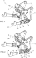
- Fig. 1 shows a longer implement attachment link 22 connected to the support arm 16.
- the safety pin 26 needs to be removed.
- the locking pin 25 is free to be removed from aligning holes 33, 35 and 56.
- the locking pin 25 is taken out of the assembly, the implement attachment link 22 can be removed as shown in Fig. 2 .
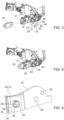
- the second type of implement attachment link 22 is inserted within the slot 21 as shown in Fig. 3 . In this case, the second implement attachment link 22 is shorter compared to the other one shown in Fig. 1 .
- the locking pin 25 is inserted through the aligning holes at the second type of implement attachment link 22, and the holes 33 and 35 at the first and second bracket 32 and 34. Finally, as shown in Fig. 4 the safety pin 26 inserted through the aligning apertures 38 and 54 holds the locking pin 25 in its position.
Landscapes
- Life Sciences & Earth Sciences (AREA)
- Engineering & Computer Science (AREA)
- Mechanical Engineering (AREA)
- Zoology (AREA)
- Soil Sciences (AREA)
- Environmental Sciences (AREA)
- Agricultural Machines (AREA)
- Chemical & Material Sciences (AREA)
- Combustion & Propulsion (AREA)
- Transportation (AREA)
Abstract
Description
- This invention relates to a hitch for a vehicle, in particular for an agricultural tractor, comprising a main frame which is mountable to a vehicle chassis, a pair of left and right lower support arms pivotably mounted to the main frame at a first end, each of the support arms at a second end comprises a holding means for holding an implement attachment link.
- For attaching an implement to an agricultural tractor, a three-point hitch is provided on the tractor. The three-point hitch may be connected to the front or the rear portion of the tractor. The three-point hitch has left and right lower links and a top link. An implement is connected to the tractor using these three linkages of the three-point hitch.
- For different types of operations, different lengths of the lower links are required. For example, for agricultural operations comparatively longer lower links are required, while for municipal operations such as snowplough, road cleaning, etc. shorter lower links are required. Hence, based on the operations, the length of the lower links needs to be selected. When one type of operation is completed and operator wants to perform another type of operation, first, the set of lower links connected to the hitch needs to be removed. Then, the new set of lower links needs to be connected as per the requirement of second type of operation. The procedure for changing the lower links is time consuming and cannot easily be done by a single person. Also, special tools are required for changing the lower links.
- If same length lower links are used for all the operations, it creates a challenge. For example, when longer length lower links which are used in agricultural applications, are used for municipal operations, it induces lateral stresses in the lower links, specially, when they hit a tree or a pole. This may damage the lower links. Also, using longer lower links for a municipal operation makes it difficult for the operator to steer the vehicle. In addition to that, extra ballast needs to be mounted on the rear side of the vehicle.
- Hence, an object of the invention is to enhance versatility and operability of a hitch for a vehicle, especially an agricultural tractor, of the type mentioned above.
- This object is achieved by a hitch for a vehicle with the features of claim 1.
- A hitch for a vehicle, in particular for an agricultural tractor, comprises a main frame which is mountable to a vehicle chassis. A pair of left and right lower support arms is pivotably mounted to the main frame at a first or rear end. Each of the support arms at a second or front end comprises a holding means for holding an implement attachment link. A releasable locking device is provided for fixing the implement attachment link to the holding means.
- The releasable locking device of the present invention enables the implement attachment links to be easily and quickly removed from the support arms. A new set of implement attachment links can then be easily connected to the support arms. The implement attachment links are selected as per the requirement of the operation and connected to the support arms. As per requirement of the operation, the implement attachment links can be different in lengths or shapes. In transport mode, the implement attachment link is either removed completely or it may be replaced by a shorter implement attachment link. This helps the operator to steer the vehicle with ease. The present invention enables tremendous reduction in time and effort while removing one set of implement attachment links and connecting a new set of implement attachment links. Changing the implement attachment links is comfortably done by hands only, without any tool.
- The hitch disclosed in respect of the present invention is a front hitch, however it can be a rear hitch also. The main frame of the hitch is mountable to the tractor. The support arms are pivotably mounted to the main frame with a nut and bolt arrangement. However, it may be mounted by any other fastening method. A hydraulic cylinder is attached to the support arms which can lift and/or lower the support arms whenever required. An electric machine may be used to lift and/or lower the support arms instead of the hydraulic cylinders. The support arms and the implement attachment links are made of a material having high load bearing capacity. The length of the support arms is kept shorter, so that it will not get the additional bending stresses which may be induced because of more length.
- Additional embodiments of the hitch are subject to the dependent claims.
- According to one of the exemplary embodiments, the implement attachment link is inserted within the holding means. The holding means comprises a slot formed by a first bracket and a second bracket. The implement attachment link is inserted within the slot in order to establish a form fit connection. The form fit connection ensures that there should not be any relative movement between implement attachment link and the support arm. The rectangular profile of the slot further helps to restrain any undesirable movement. The first bracket and the second bracket are made as a single unit. However, it is possible that, it may be made of two different elements connected by a fastening member or welded together. The slot of the support member and the implement attachment link are coated with a wear resistant material. The holes are provided on the first bracket, the second bracket and the implement attachment link. The second bracket of the slot has a flange around the hole on an external side. The flange further has two diametrical apertures. A cap is provided over the hole on the first bracket. The slot and the implement attachment link are rectangular in shape; however, it will be appreciated that it can be a circular shape, a square shape, a polygonal shape, etc.
- Furthermore, the locking device comprises a locking pin which is inserted through aligning holes on the first bracket, the second bracket and the implement attachment link. The length of the locking pin is more than the width of the slot. The locking pin has a head at one side and an aperture at the other side. The head has a flat surface which aligns with the cap provided over the hole on the first bracket.
- This stops the implement attachment link from rotating within the support arm, ensuring a rigid connection between the implement attachment link and the support arm. Furthermore, the flat surface on the head of the locking pin and the cap provided over the hole on the first bracket aligns the apertures on the locking pin and the diametrical apertures on the flange of the second bracket. A safety pin is inserted through the aligning apertures on the locking pin and diametrical apertures on the flanges of the second bracket. The safety pin does not allow the locking pin to get out of the assembly. The locking pin is inserted through the assembly of the first bracket, the second bracket and the implement attachment link and then retained in that position by the safety pin. The locking pin is also made of a high stress bearable material with resistance coating. The aligning holes and the locking pin are circular in shape; however, it will be appreciated that it may be of any other shape such as a square, a polygonal, a rectangular, etc.
- The locking pin can be inserted manually through the aligning holes. The locking pin has a gripping portion which helps operator to comfortably push and pull the locking pin in and out of the aligning holes. The locking pin head is provided with a chain which is connected to the support arm. While changing the implement attachment link, operator sometimes lose the locking pin. The chain attached to the locking pin keeps the locking pin always close to the assembly. This further helps reducing the time for changing the implement attachment link. It is possible that a spring-loaded mechanism can be used to push the locking pin through the aligning holes. The locking device can be any other mechanism such as spring-loaded hook arrangement.
- A hitch according to the invention is explained in greater detail below on the basis of the enclosed drawings, wherein matching reference numbers designate components which are structurally identical or comparable in terms of their function. In the drawings:
- Fig. 1
- shows a perspective view of an exemplary embodiment of the hitch according to the invention for an agricultural tractor for a first type of implement,
- Fig. 2
- shows the hitch according to
Fig. 1 in a disassembled state, - Fig. 3
- shows the hitch according to the present invention for a second type of implement in a disassembled state,
- Fig. 4
- shows assembly of the hitch components shown in
Fig. 3 for the second type of implement, - Fig. 5
- shows a perspective view of a support arm having a flange with diametrically placed apertures,
- Fig. 6
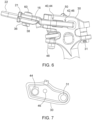
- shows a bottom view of the hitch according to present invention, and
- Fig. 7
- shows a side view of a pivotable extension of a main frame.
-
Fig. 1 shows a perspective view of ahitch 10 for an agricultural tractor (not shown). Thehitch 10 comprises amain frame 12 which is mounted to the tractor by afastening member 14. Thefastening member 14 is a nut and bolt arrangement. A pair ofextensions 30 is attached on both sides to the bottom of themain frame 12 in a pivotable manner. A pair ofsupport arms 16 is connected to thepivotable extension 30. Further, an implementattachment link 22 is fixed to each of thesupport arms 16, specifically the implementattachment link 22 is inserted within thesupport arm 16. The implementattachment link 22 has acoupling member 28 at a free end. Thehitch 10 also comprises anupper link 29. The implement is attached to thehitch 10 using theupper link 29 and thecoupling members 28 on both the implement attachment links 22. - As shown in
Fig. 7 , at a rear end, theextension 30 is pivotably connected to themain frame 12 by apivotable connection 31. Theextension 30 has twoholes support arm 16 has ahole 40 and ahole 42. Afastening element 48 is inserted through theholes 44 on theextension 30 and thehole 40 on thesupport arm 16. Anotherfastening element 50 is inserted through theholes 46 on theextension 30 and thehole 42 on thesupport arm 16. The fastening provided at two places withfastening element support arm 16 and theextension 30. The fastening element is a nut and bolt arrangement. - A
hydraulic cylinder 58 is attached to themain frame 12 at an upper side, and at a lower side, it is connected to thesupport arm 16 by thefastening element 48. Theextension 30, thesupport arm 16 and thehydraulic cylinder 58 are held together by thefastening element 48. Thehydraulic cylinder 58 is used to lift and/or lower thesupport arm 16 through thepivotable connection 31. - As shown in
Fig. 5 , thesupport arm 16 has a holding means 20 at a front end. The holding means 20 comprises aslot 21 formed by the first andsecond bracket bracket bracket 32 has ahole 33 andbracket 34 has ahole 35. Acap 60 is provided over thehole 33 of thefirst bracket 32. Aflange 36 is provided on an external side of thehole 35 on thesecond bracket 34 of theslot 21. Theflange 36 has two diametrically placedapertures 38 to receive thesafety pin 26. - As shown in
Fig. 2 , the implementattachment link 22 has thecoupling member 28 at a front end and ahole 56 at a rear end. The implementattachment link 22 is inserted within theslot 21 of thesupport arm 16 to establish a form fit connection. A lockingdevice 24 which comprises a lockingpin 25 is inserted through the aligningholes first bracket 32, thesecond bracket 34 and the implementattachment link 22, respectively. The lockingpin 25 has ahead 52 at one end and anaperture 54 at the other end. Thehead 52, further, has aflat surface 53. - The
flat surface 53 and thecap 60 provided over thehole 33 of thefirst bracket 32 stops the implementattachment link 22 to rotate within thesupport arm 16, ensuring a rigid connection. Further, theflat surface 53 and thecap 60 align theaperture 54 of the lockingpin 25 and thediametrical apertures 38 on theflange 36 of thesecond bracket 34. Thesafety pin 26 is inserted through the alignedapertures safety pin 26 does not allow thelocking pin 25 to come out while in operation. - The locking
pin 25 and the aligningholes first bracket 32, thesecond bracket 34 and the implementattachment link 22 respectively are circular in shape. However, the person skilled in the art will appreciate other shapes such as rectangular shape, a square shape, a polygonal shape, etc. - The
aperture 54 and thediametrical apertures 38 on theflange 36 are circular in shape. However, the person skilled in the art will appreciate other shapes such as rectangular shape, a square shape, a polygonal shape, etc. - The implement
attachment link 22 and theslot 21 are rectangular in shape. However, the person skilled in the art will appreciate other shapes such as circular shape, a square shape, a polygonal shape, etc. The rectangular profile restricts the undesirable movement between the implementattachment link 22 and thesupport arm 16. - A chain (not shown) is with a first end attached to the
head 52 of the lockingpin 25. With a second end, the chain is connected to thesupport arm 16. While changing the implementattachment link 22, the lockingpin 25 is removed. The chain attached to thehead 52 of the lockingpin 25 keeps the lockingpin 25 close to supportarm 16 so that it will not get lost. - As per another embodiment (not shown) of the invention the locking
pin 25 is inserted through the aligningholes -
Figs. 1 to 4 explain the sequence of changing the implementattachment link 22.Fig. 1 shows a longer implementattachment link 22 connected to thesupport arm 16. For removing the implementattachment link 22 shown inFig. 1 , first thesafety pin 26 needs to be removed. Once thesafety pin 26 is removed, the lockingpin 25 is free to be removed from aligningholes pin 25 is taken out of the assembly, the implementattachment link 22 can be removed as shown inFig. 2 . As per requirement of the operation, the second type of implementattachment link 22 is inserted within theslot 21 as shown inFig. 3 . In this case, the second implementattachment link 22 is shorter compared to the other one shown inFig. 1 . The lockingpin 25 is inserted through the aligning holes at the second type of implementattachment link 22, and theholes second bracket Fig. 4 thesafety pin 26 inserted through the aligningapertures pin 25 in its position. - For changing of the implement
attachment link 22, no tool is required. It is done by hands only. The present invention helps to reduce the time and effort of changing the implementattachment link 22.
Claims (13)
- A hitch for a vehicle, in particular for an agricultural tractor, comprisinga main frame (12) which is mountable to a vehicle chassis,a pair of left and right lower support arms (16) pivotably mounted to the main frame (12) at a first end, each of the support arms (16) at a second end comprises a holding means (20) for holding an implement attachment link (22), characterized in that a releasable locking device (24) is provided for fixing the implement attachment link (22) to the holding means (20).
- The hitch according to claim 1, characterized in that the implement attachment link (22) is inserted within the holding means (20).
- The hitch according to claim 1, characterized in that the holding means (20) comprises a slot (21) formed by a first bracket (32) and a second bracket (34), the implement attachment link (22) is inserted between the first bracket (32) and the second bracket (34) in order to establish a form fit connection.
- The hitch according to claim 3, characterized in that the locking device (24) comprises a locking pin (25) which is inserted through aligning holes (33, 35 and 56) in the first bracket, the second bracket and the implement attachment link.
- The hitch according to claim 4, characterized in that the locking pin (25) at one side has a head (52) and an aperture (54) at the other side to receive the safety pin (26).
- The hitch according to claim 4, characterized in that the second bracket (34) has a flange (36) around the hole (35) at an external side, wherein there are two diametrical apertures (38) on the flange (36) to receive the safety pin (26).
- The hitch according to claims 5 and 6, characterized in that the safety pin (26) is inserted through the aligning apertures (54 and 38) on the locking pin (25) and the flange (36).
- The hitch according to claims 3 and 4, characterized in that a cap (60) is provided above the hole (33) of the first bracket (32) of support arm (16) which aligns with a flat surface (53) of the head (52) of the locking pin (25) in its mounted condition.
- The hitch according to the at least one of the preceding claims, characterized in that the holding means (20) and the implement attachment link (22) has a shape selected from a group consisting of a rectangular shape, a circular shape, a square shape, a polygonal shape.
- The hitch according to claims 4, 5 and 6, characterized in that the aligning holes (33, 35 and 56), locking pin (25), and aligning apertures (54 and 38) on the locking pin (25) and flange (36) have a shape selected from a group consisting of a rectangular shape, a circular shape, a square shape, a polygonal shape.
- The hitch according to at least one of the preceding claims, characterized in that the hitch (10) is mountable to the front of the vehicle chassis.
- The hitch according to at least one of the preceding claims, characterized in that the support arms (16) are liftable hydraulically.
- The hitch according to the claim 4, characterized in that the locking pin (25) is forced by a spring-loaded mechanism into the aligning holes (33, 35, 56).
Priority Applications (2)
| Application Number | Priority Date | Filing Date | Title |
|---|---|---|---|
| EP22199030.2A EP4344522B1 (en) | 2022-09-30 | 2022-09-30 | Hitch for a vehicle |
| US18/477,781 US20240107929A1 (en) | 2022-09-30 | 2023-09-29 | Hitch for a vehicle |
Applications Claiming Priority (1)
| Application Number | Priority Date | Filing Date | Title |
|---|---|---|---|
| EP22199030.2A EP4344522B1 (en) | 2022-09-30 | 2022-09-30 | Hitch for a vehicle |
Publications (2)
| Publication Number | Publication Date |
|---|---|
| EP4344522A1 true EP4344522A1 (en) | 2024-04-03 |
| EP4344522B1 EP4344522B1 (en) | 2025-04-16 |
Family
ID=83508731
Family Applications (1)
| Application Number | Title | Priority Date | Filing Date |
|---|---|---|---|
| EP22199030.2A Active EP4344522B1 (en) | 2022-09-30 | 2022-09-30 | Hitch for a vehicle |
Country Status (2)
| Country | Link |
|---|---|
| US (1) | US20240107929A1 (en) |
| EP (1) | EP4344522B1 (en) |
Citations (6)
| Publication number | Priority date | Publication date | Assignee | Title |
|---|---|---|---|---|
| US2828974A (en) * | 1955-08-25 | 1958-04-01 | John E Jameson | Automatic coupling devices for vehicles |
| JPH04115974U (en) * | 1991-03-28 | 1992-10-15 | スズキ株式会社 | Connection structure of power transmission members |
| US6062321A (en) * | 1997-10-22 | 2000-05-16 | Defrancq; Hubert | Lifting device, particularly a front lift for an agricultural tractor or the like |
| FR2964822A1 (en) * | 2010-09-20 | 2012-03-23 | Deere & Co | FOLDING HITCHING ARM FOLDING. |
| US20150122518A1 (en) * | 2013-11-07 | 2015-05-07 | Cnh Industrial America Llc | Implement for a tractor hitch |
| EP4029359A1 (en) * | 2021-01-19 | 2022-07-20 | CNH Industrial Italia S.p.A. | Front lower links system for super steer agricultural vehicle and super steer agricultural vehicle including the front lower links system |
Family Cites Families (6)
| Publication number | Priority date | Publication date | Assignee | Title |
|---|---|---|---|---|
| US5593264A (en) * | 1995-08-15 | 1997-01-14 | Case Corporation | Pin retainer and flag assembly |
| US6612380B2 (en) * | 2001-07-25 | 2003-09-02 | Donald D. Pyle | Tractor attachment for three point hitch |
| US6672568B1 (en) * | 2002-06-13 | 2004-01-06 | Richard J. Rawlinson | Winch assembly for a tractor |
| DE10315174B3 (en) * | 2003-04-03 | 2004-04-29 | Deere & Company, Moline | Holding device for the upper connecting rod of a three-point linkage of a tractor comprises a first and a second plate, each having a horizontal bore receiving a displaceable rotating bolt |
| DE102018218408A1 (en) * | 2018-10-26 | 2020-04-30 | Deere & Company | Power lift for an agricultural tractor |
| US11617293B2 (en) * | 2020-03-12 | 2023-04-04 | Deere & Company | Hitch assembly for a work vehicle |
-
2022
- 2022-09-30 EP EP22199030.2A patent/EP4344522B1/en active Active
-
2023
- 2023-09-29 US US18/477,781 patent/US20240107929A1/en active Pending
Patent Citations (6)
| Publication number | Priority date | Publication date | Assignee | Title |
|---|---|---|---|---|
| US2828974A (en) * | 1955-08-25 | 1958-04-01 | John E Jameson | Automatic coupling devices for vehicles |
| JPH04115974U (en) * | 1991-03-28 | 1992-10-15 | スズキ株式会社 | Connection structure of power transmission members |
| US6062321A (en) * | 1997-10-22 | 2000-05-16 | Defrancq; Hubert | Lifting device, particularly a front lift for an agricultural tractor or the like |
| FR2964822A1 (en) * | 2010-09-20 | 2012-03-23 | Deere & Co | FOLDING HITCHING ARM FOLDING. |
| US20150122518A1 (en) * | 2013-11-07 | 2015-05-07 | Cnh Industrial America Llc | Implement for a tractor hitch |
| EP4029359A1 (en) * | 2021-01-19 | 2022-07-20 | CNH Industrial Italia S.p.A. | Front lower links system for super steer agricultural vehicle and super steer agricultural vehicle including the front lower links system |
Also Published As
| Publication number | Publication date |
|---|---|
| US20240107929A1 (en) | 2024-04-04 |
| EP4344522B1 (en) | 2025-04-16 |
Similar Documents
| Publication | Publication Date | Title |
|---|---|---|
| EP1527666B1 (en) | Quick attachment system. | |
| US5692850A (en) | High visibility coupler for front end loader | |
| US5466113A (en) | Arrangement for the retention of an implement to a lifting gear | |
| US6386821B1 (en) | Mounting system for mid-mount front end loaders | |
| US6168369B1 (en) | Carrier retainer system | |
| US6056069A (en) | Latch for an adjustable link assembly | |
| US8777546B2 (en) | System for attaching a tool to a work machine | |
| US5876019A (en) | Winching apparatus for all-terrain vehicle | |
| US20090269181A1 (en) | Adjustable gripping arms for lifting machine | |
| US6035941A (en) | Tractor with a front loader | |
| US10414633B1 (en) | Grappling assembly for use with utility equipment | |
| EP4344522A1 (en) | Hitch for a vehicle | |
| US2929458A (en) | Holding device for non-pivotally securing a pivotal link to a tractor | |
| US20150122517A1 (en) | Implement hitch for a tractor | |
| US10233612B2 (en) | Tractor attachment and tractor attachment kit | |
| US20040076504A1 (en) | Excavator coupler assembly | |
| CA2515636C (en) | Pivotal connector assembly | |
| US5544708A (en) | Hitch apparatus for tractor lift arms | |
| EP2140748A1 (en) | Tractor hitches | |
| US3127193A (en) | Tandem tractor hitch | |
| KR200493426Y1 (en) | Tong attachment for excavator | |
| US4071154A (en) | Bracket connection for backhoe and skip loader | |
| EP1306489A1 (en) | Front loader | |
| JPH10140853A (en) | Disassembling fork | |
| JPH0525367Y2 (en) |
Legal Events
| Date | Code | Title | Description |
|---|---|---|---|
| PUAI | Public reference made under article 153(3) epc to a published international application that has entered the european phase |
Free format text: ORIGINAL CODE: 0009012 |
|
| STAA | Information on the status of an ep patent application or granted ep patent |
Free format text: STATUS: THE APPLICATION HAS BEEN PUBLISHED |
|
| AK | Designated contracting states |
Kind code of ref document: A1 Designated state(s): AL AT BE BG CH CY CZ DE DK EE ES FI FR GB GR HR HU IE IS IT LI LT LU LV MC MK MT NL NO PL PT RO RS SE SI SK SM TR |
|
| STAA | Information on the status of an ep patent application or granted ep patent |
Free format text: STATUS: REQUEST FOR EXAMINATION WAS MADE |
|
| STAA | Information on the status of an ep patent application or granted ep patent |
Free format text: STATUS: EXAMINATION IS IN PROGRESS |
|
| 17P | Request for examination filed |
Effective date: 20241004 |
|
| RBV | Designated contracting states (corrected) |
Designated state(s): AL AT BE BG CH CY CZ DE DK EE ES FI FR GB GR HR HU IE IS IT LI LT LU LV MC MK MT NL NO PL PT RO RS SE SI SK SM TR |
|
| GRAP | Despatch of communication of intention to grant a patent |
Free format text: ORIGINAL CODE: EPIDOSNIGR1 |
|
| STAA | Information on the status of an ep patent application or granted ep patent |
Free format text: STATUS: GRANT OF PATENT IS INTENDED |
|
| 17Q | First examination report despatched |
Effective date: 20241112 |
|
| INTG | Intention to grant announced |
Effective date: 20241210 |
|
| GRAS | Grant fee paid |
Free format text: ORIGINAL CODE: EPIDOSNIGR3 |
|
| GRAA | (expected) grant |
Free format text: ORIGINAL CODE: 0009210 |
|
| STAA | Information on the status of an ep patent application or granted ep patent |
Free format text: STATUS: THE PATENT HAS BEEN GRANTED |
|
| AK | Designated contracting states |
Kind code of ref document: B1 Designated state(s): AL AT BE BG CH CY CZ DE DK EE ES FI FR GB GR HR HU IE IS IT LI LT LU LV MC MK MT NL NO PL PT RO RS SE SI SK SM TR |
|
| REG | Reference to a national code |
Ref country code: GB Ref legal event code: FG4D |
|
| REG | Reference to a national code |
Ref country code: CH Ref legal event code: EP |
|
| REG | Reference to a national code |
Ref country code: IE Ref legal event code: FG4D |
|
| REG | Reference to a national code |
Ref country code: DE Ref legal event code: R096 Ref document number: 602022013178 Country of ref document: DE |
|
| PG25 | Lapsed in a contracting state [announced via postgrant information from national office to epo] |
Ref country code: NL Free format text: LAPSE BECAUSE OF FAILURE TO SUBMIT A TRANSLATION OF THE DESCRIPTION OR TO PAY THE FEE WITHIN THE PRESCRIBED TIME-LIMIT Effective date: 20250416 |
|
| REG | Reference to a national code |
Ref country code: AT Ref legal event code: MK05 Ref document number: 1784825 Country of ref document: AT Kind code of ref document: T Effective date: 20250416 |
|
| PG25 | Lapsed in a contracting state [announced via postgrant information from national office to epo] |
Ref country code: FI Free format text: LAPSE BECAUSE OF FAILURE TO SUBMIT A TRANSLATION OF THE DESCRIPTION OR TO PAY THE FEE WITHIN THE PRESCRIBED TIME-LIMIT Effective date: 20250416 Ref country code: ES Free format text: LAPSE BECAUSE OF FAILURE TO SUBMIT A TRANSLATION OF THE DESCRIPTION OR TO PAY THE FEE WITHIN THE PRESCRIBED TIME-LIMIT Effective date: 20250416 Ref country code: PT Free format text: LAPSE BECAUSE OF FAILURE TO SUBMIT A TRANSLATION OF THE DESCRIPTION OR TO PAY THE FEE WITHIN THE PRESCRIBED TIME-LIMIT Effective date: 20250818 |
|
| PGFP | Annual fee paid to national office [announced via postgrant information from national office to epo] |
Ref country code: DE Payment date: 20250820 Year of fee payment: 4 |
|
| REG | Reference to a national code |
Ref country code: LT Ref legal event code: MG9D |
|
| PG25 | Lapsed in a contracting state [announced via postgrant information from national office to epo] |
Ref country code: NO Free format text: LAPSE BECAUSE OF FAILURE TO SUBMIT A TRANSLATION OF THE DESCRIPTION OR TO PAY THE FEE WITHIN THE PRESCRIBED TIME-LIMIT Effective date: 20250716 Ref country code: GR Free format text: LAPSE BECAUSE OF FAILURE TO SUBMIT A TRANSLATION OF THE DESCRIPTION OR TO PAY THE FEE WITHIN THE PRESCRIBED TIME-LIMIT Effective date: 20250717 |
|
| PG25 | Lapsed in a contracting state [announced via postgrant information from national office to epo] |
Ref country code: PL Free format text: LAPSE BECAUSE OF FAILURE TO SUBMIT A TRANSLATION OF THE DESCRIPTION OR TO PAY THE FEE WITHIN THE PRESCRIBED TIME-LIMIT Effective date: 20250416 |
|
| PG25 | Lapsed in a contracting state [announced via postgrant information from national office to epo] |
Ref country code: BG Free format text: LAPSE BECAUSE OF FAILURE TO SUBMIT A TRANSLATION OF THE DESCRIPTION OR TO PAY THE FEE WITHIN THE PRESCRIBED TIME-LIMIT Effective date: 20250416 |
|
| PG25 | Lapsed in a contracting state [announced via postgrant information from national office to epo] |
Ref country code: HR Free format text: LAPSE BECAUSE OF FAILURE TO SUBMIT A TRANSLATION OF THE DESCRIPTION OR TO PAY THE FEE WITHIN THE PRESCRIBED TIME-LIMIT Effective date: 20250416 |
|
| PG25 | Lapsed in a contracting state [announced via postgrant information from national office to epo] |
Ref country code: AT Free format text: LAPSE BECAUSE OF FAILURE TO SUBMIT A TRANSLATION OF THE DESCRIPTION OR TO PAY THE FEE WITHIN THE PRESCRIBED TIME-LIMIT Effective date: 20250416 |
|
| PGFP | Annual fee paid to national office [announced via postgrant information from national office to epo] |
Ref country code: FR Payment date: 20250925 Year of fee payment: 4 |
|
| PG25 | Lapsed in a contracting state [announced via postgrant information from national office to epo] |
Ref country code: RS Free format text: LAPSE BECAUSE OF FAILURE TO SUBMIT A TRANSLATION OF THE DESCRIPTION OR TO PAY THE FEE WITHIN THE PRESCRIBED TIME-LIMIT Effective date: 20250716 |
|
| PG25 | Lapsed in a contracting state [announced via postgrant information from national office to epo] |
Ref country code: IS Free format text: LAPSE BECAUSE OF FAILURE TO SUBMIT A TRANSLATION OF THE DESCRIPTION OR TO PAY THE FEE WITHIN THE PRESCRIBED TIME-LIMIT Effective date: 20250816 |
|
| PG25 | Lapsed in a contracting state [announced via postgrant information from national office to epo] |
Ref country code: LV Free format text: LAPSE BECAUSE OF FAILURE TO SUBMIT A TRANSLATION OF THE DESCRIPTION OR TO PAY THE FEE WITHIN THE PRESCRIBED TIME-LIMIT Effective date: 20250416 |
|
| PG25 | Lapsed in a contracting state [announced via postgrant information from national office to epo] |
Ref country code: DK Free format text: LAPSE BECAUSE OF FAILURE TO SUBMIT A TRANSLATION OF THE DESCRIPTION OR TO PAY THE FEE WITHIN THE PRESCRIBED TIME-LIMIT Effective date: 20250416 Ref country code: SM Free format text: LAPSE BECAUSE OF FAILURE TO SUBMIT A TRANSLATION OF THE DESCRIPTION OR TO PAY THE FEE WITHIN THE PRESCRIBED TIME-LIMIT Effective date: 20250416 |
|
| REG | Reference to a national code |
Ref country code: DE Ref legal event code: R097 Ref document number: 602022013178 Country of ref document: DE |
|
| PG25 | Lapsed in a contracting state [announced via postgrant information from national office to epo] |
Ref country code: CZ Free format text: LAPSE BECAUSE OF FAILURE TO SUBMIT A TRANSLATION OF THE DESCRIPTION OR TO PAY THE FEE WITHIN THE PRESCRIBED TIME-LIMIT Effective date: 20250416 |
|
| PG25 | Lapsed in a contracting state [announced via postgrant information from national office to epo] |
Ref country code: EE Free format text: LAPSE BECAUSE OF FAILURE TO SUBMIT A TRANSLATION OF THE DESCRIPTION OR TO PAY THE FEE WITHIN THE PRESCRIBED TIME-LIMIT Effective date: 20250416 |
|
| PG25 | Lapsed in a contracting state [announced via postgrant information from national office to epo] |
Ref country code: SK Free format text: LAPSE BECAUSE OF FAILURE TO SUBMIT A TRANSLATION OF THE DESCRIPTION OR TO PAY THE FEE WITHIN THE PRESCRIBED TIME-LIMIT Effective date: 20250416 |
|
| PG25 | Lapsed in a contracting state [announced via postgrant information from national office to epo] |
Ref country code: IT Free format text: LAPSE BECAUSE OF FAILURE TO SUBMIT A TRANSLATION OF THE DESCRIPTION OR TO PAY THE FEE WITHIN THE PRESCRIBED TIME-LIMIT Effective date: 20250416 |
|
| PLBE | No opposition filed within time limit |
Free format text: ORIGINAL CODE: 0009261 |
|
| STAA | Information on the status of an ep patent application or granted ep patent |
Free format text: STATUS: NO OPPOSITION FILED WITHIN TIME LIMIT |
|
| REG | Reference to a national code |
Ref country code: CH Ref legal event code: L10 Free format text: ST27 STATUS EVENT CODE: U-0-0-L10-L00 (AS PROVIDED BY THE NATIONAL OFFICE) Effective date: 20260225 |
|
| PG25 | Lapsed in a contracting state [announced via postgrant information from national office to epo] |
Ref country code: RO Free format text: LAPSE BECAUSE OF FAILURE TO SUBMIT A TRANSLATION OF THE DESCRIPTION OR TO PAY THE FEE WITHIN THE PRESCRIBED TIME-LIMIT Effective date: 20250416 |
|
| 26N | No opposition filed |
Effective date: 20260119 |