EP4344374A1 - Case and method for using same - Google Patents
Case and method for using same Download PDFInfo
- Publication number
- EP4344374A1 EP4344374A1 EP22804453.3A EP22804453A EP4344374A1 EP 4344374 A1 EP4344374 A1 EP 4344374A1 EP 22804453 A EP22804453 A EP 22804453A EP 4344374 A1 EP4344374 A1 EP 4344374A1
- Authority
- EP
- European Patent Office
- Prior art keywords
- shutter member
- case
- slide member
- slide
- discharge port
- Prior art date
- Legal status (The legal status is an assumption and is not a legal conclusion. Google has not performed a legal analysis and makes no representation as to the accuracy of the status listed.)
- Pending
Links
Images





Classifications
-
- H—ELECTRICITY
- H05—ELECTRIC TECHNIQUES NOT OTHERWISE PROVIDED FOR
- H05K—PRINTED CIRCUITS; CASINGS OR CONSTRUCTIONAL DETAILS OF ELECTRIC APPARATUS; MANUFACTURE OF ASSEMBLAGES OF ELECTRICAL COMPONENTS
- H05K13/00—Apparatus or processes specially adapted for manufacturing or adjusting assemblages of electric components
- H05K13/04—Mounting of components, e.g. of leadless components
- H05K13/043—Feeding one by one by other means than belts
- H05K13/0434—Feeding one by one by other means than belts with containers
-
- H—ELECTRICITY
- H05—ELECTRIC TECHNIQUES NOT OTHERWISE PROVIDED FOR
- H05K—PRINTED CIRCUITS; CASINGS OR CONSTRUCTIONAL DETAILS OF ELECTRIC APPARATUS; MANUFACTURE OF ASSEMBLAGES OF ELECTRICAL COMPONENTS
- H05K13/00—Apparatus or processes specially adapted for manufacturing or adjusting assemblages of electric components
- H05K13/0084—Containers and magazines for components, e.g. tube-like magazines
-
- H—ELECTRICITY
- H05—ELECTRIC TECHNIQUES NOT OTHERWISE PROVIDED FOR
- H05K—PRINTED CIRCUITS; CASINGS OR CONSTRUCTIONAL DETAILS OF ELECTRIC APPARATUS; MANUFACTURE OF ASSEMBLAGES OF ELECTRICAL COMPONENTS
- H05K13/00—Apparatus or processes specially adapted for manufacturing or adjusting assemblages of electric components
- H05K13/02—Feeding of components
- H05K13/028—Simultaneously loading a plurality of loose objects, e.g. by means of vibrations, pressure differences, magnetic fields
Definitions
- the present invention relates to a case for accommodating electronic components such as chip components and a method of using the case.
- Japanese Unexamined Patent Application, Publication No. 2009-295618 discloses a case in which a plurality of electronic components in a loose state are collectively accommodated, and the electronic components are dropped onto a feeder by their own weight from a take-out port located at a bottom portion.
- electronic components are accommodated from an opening (refill opening) opened upward, and the opening is opened and closed by an opening/closing lid.
- Patent Document 1 Japanese Unexamined Patent Application, Publication No. 2009-295618
- An embodiment of the present invention provides a case in which an opening serving as an inlet/outlet port of components into/from the case cannot be easily opened.
- An embodiment of the present application provides a case including: a case body including an accommodation space that accommodates a plurality of components and an opening for taking the plurality of components into and out of the accommodation space; a shutter member that is provided in the case body in a slidable manner and opens and closes the opening by sliding; and a slide member including a first plate-shaped portion that is provided in the case body, slidable relative to the shutter member along a sliding direction of the shutter member, and provided on an outer side of the shutter member in the case body in a superimposable manner, in which, in a state in which the shutter member closes the discharge port, the slide member is superimposed on the shutter member so that the slide member is integrally slidable with the shutter member.
- FIG. 1 is a side view of the inside of a case 1 according to an embodiment
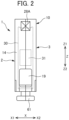
- FIG. 2 is a front view of the case 1 viewed from the front
- FIG. 3 is a bottom view of the case 1.
- FIG. 4 is an enlarged side view showing the inside of the front portion of the case 1.
- the case 1 accommodates therein a plurality of electronic components M as components in a loose state.
- the case 1 accommodating a plurality of electronic components M is set in a feeder (not shown), and the electronic components M are discharged from the case 1 by vibration of the feeder and supplied to a mounting device or the like.
- Each of the electronic components M of the present embodiment is, for example, a small rectangular parallelepiped electronic component having a length of 1.2 mm or less in the longitudinal direction. Examples of such electronic components include capacitors and inductors, but the present embodiment is not limited thereto.
- the arrows X, Y, and Z shown in any one of FIGS. 1 , 2 , and 3 respectively indicate the left-right direction, the front-rear direction, and the upper-lower direction of the case 1 when the case 1 is set in the feeder.
- the left side in the left-right direction X is denoted by X1
- the right side is denoted by X2
- the front side in the front-rear direction Y is denoted by Y1
- the rear side is denoted by Y2
- the upper side in the upper-lower direction Z is denoted by Z1
- the lower side is denoted by Z2.
- any one of the left-right direction X, the longitudinal direction Y, and the upper-lower direction Z is similarly applied.
- the left-right direction, the front-rear direction, and the upper-lower direction in the following description are based on the directions indicated by the arrows.
- the case 1 includes a case body 10 that accommodates a plurality of electronic components M, a shutter member 30 that opens and closes a discharge port 19 of the case body 10, and a slide member 35 that is operated to slide the shutter member 30.
- the discharge port 19 is an example of an opening.
- the case body 10 are divided into the first member 2 and the second member 3 as left and right portions.
- the first member 2 and the second member 3 are joined to each other to provide the case body 10.
- FIG. 1 shows the interior of the second member 3 on the right side without the first member 2 on the left side.
- the case body 10 has a flat box shape that is long in the front-rear direction and thin in the left-right direction.
- first member 2 and the second member 3 are not individually described, and a configuration in which the first member 2 and the second member 3 are joined to each other will be described.
- the case body 10 includes an accommodation space 11 for accommodating the plurality of electronic components M in a loose state.
- the case body 10 includes a top plate portion 12 and a bottom plate portion 13 which extend in the front-rear direction, a front wall portion 14 and a rear wall portion 15 which extend in the upper-lower direction, a pair of left and right side wall portions 16, and a sloped plate portion 17 which partitions the interior of the case body 10 vertically.
- the rear wall portion 15 includes an outer rear wall portion 15a functioning as an outer surface and an inner rear wall portion 15b in front of the outer rear wall portion.
- the discharge port 19 is an opening for taking the electronic components M into and out of the accommodation space 11.
- the discharge port 19 is provided at the lower portion of the front wall portion 14.
- the discharge port 19 has a rectangular shape.
- the shape of the discharge port 19 is not limited to a rectangular shape, and the discharge port 19 may include, for example, an opening having a circular shape, an elliptical shape, or the like.
- the discharge port 19 is opened and closed by the shutter member 30 described later.
- FIG. 1 shows the case 1 in a shipped state in which a predetermined number of electronic components M are accommodated in the accommodation space 11 and the discharge port 19 is closed by the shutter member 30.
- the sloped plate portion 17 extends between the left and right side wall portions 16 and extends from the inner rear wall portion 15b to the lower portion of the discharge port 19.
- the sloped plate portion 17 is provided below the center of the case body 10 in the upper-lower direction in the case body 10.
- the upper side of the sloped plate portion 17 functions as the accommodation space 11
- the lower side of the sloped plate portion 17 functions as the lower space 18.
- the sloped plate portion 17 is sloped at a downward gradient toward the discharge port 19, and an upper surface of the sloped plate portion 17 includes a sloped surface 17a that is sloped at a downward gradient toward the discharge port 19.
- the slope angle ⁇ 1 of the sloped surface 17a is about 10° with respect to the horizontal direction when the case 1 is set in the feeder.
- the slope angle ⁇ 1 of the sloped surface 17a is preferably 3° or more and 10° or less.
- the slope angle ⁇ 1 of the sloped surface 17a is appropriately adjusted according to the vibration condition of the feeder.
- an RFID tag 27 having an elongated band shape in the front-rear direction is provided at a rear portion of the lower space 18.
- the RFID tag 27 has a stickerlike shape and property, and attached to the upper surface of the bottom plate portion 13.
- the RFID tag 27 has a known configuration including a transmission/reception unit, memory, an antenna, and the like.
- a reader/writer that reads and writes information from and to the RFID tag 27 is provided in the feeder in which the case 1 is set.
- the case body 10 includes an upper grip portion 28A and a rear grip portion 28B.
- the upper grip portions 28A are a pair of front and rear recesses provided at both front and rear ends of the upper side of the case body 10.
- the rear grip portions 28B are a pair of upper and lower recesses respectively provided at the upper and lower ends of the rear side of the case body 10.
- Each of the upper grip portions 28A and the rear grip portions 28B is gripped by a robot hand, for example, when the case 1 is carried by the robot hand.
- the case body 10 includes a plurality of claw portions on the bottom surface for detachably setting the case body 10 in the feeder.
- a first claw portion 61, a second claw portion 62, and a third claw portion 63 are provided on the bottom surface at intervals in the front-rear direction.
- the first claw portion 61, the second claw portion 62, and the third claw portion 63 are provided integrally with the case body 10.
- Each of the first claw portion 61 and the second claw portion 62 includes a T-shaped slot having an inverted T-shape in a cross section in a plane extending in the up, down, left, and right directions.
- the third claw portion 63 is an L-shaped plate piece extending rearward in a side view.
- the shutter member 30 slides to open and close the discharge port 19.
- the shutter member 30 continuously extends from the bottom plate portion 13 to the front wall portion 14, and is slidable along the extending direction.
- the shutter member 30 is an elongated band-shaped film member.
- the shutter member 30 is made of a flexible material having a certain degree of rigidity and is bendable, such as PET(Polyethylene terephthalate).
- the thickness of the shutter member 30 made of such a film-shaped member is not limited, but is preferably, for example, 0.1 mm or more and 0.5 mm or less.
- the width of the shutter member 30 is slightly larger than the width of the discharge port 19, and has a width capable of covering the discharge port 19 without a gap.
- an opening 31 having substantially the same shape as the discharge port 19 is provided in the front end portion of the shutter member 30.
- the shutter member 30 can slide along the lower guide portion 5 and the upper guide portion 4 of the case body 10.
- the lower guide portion 5 is provided above the bottom plate portion 13, and the upper guide portion 4 is provided above the discharge port 19.
- the rear side of the shutter member 30 slides substantially horizontally along the lower guide portion 5, and the front side of the shutter member 30 slides vertically along the upper guide portion 4.
- Each of the lower guide portion 5 and the upper guide portion 4 provides a passage for slidably holding the shutter member 30 while maintaining the surface direction of the shutter member 30 along the left-right direction.
- the lower guide portion 5 includes a first lower guide portion 51 provided below the discharge port 19 and a second lower guide portion 52 provided behind the first lower guide portion 51.
- the second lower guide portion 52 is configured by a gap provided between the bottom plate portion 13 and the protruding portion 17c protruding downward at the front end portion of the sloped plate portion 17.
- the first lower guide portion 51 includes a front end surface 17b of the sloped plate portion 17 and a front end portion 29 of the bottom plate portion 13.
- the rear portion of the shutter member 30 passes through the gap between the protruding portion 17c and the bottom plate portion 13 in the second lower guide portion 52. With such a configuration, the rear portion of the shutter member 30 slides in the front-rear direction immediately above the bottom plate portion 13. In the first lower guide portion 51, the shutter member 30 slides along the front end portion 29 of the bottom plate portion 13 which curves in a recessed manner in the front-rear direction, and further slides along the front end surface 17b of the sloped plate portion 17, whereby the shutter member 30 bends upward at an angle of approximately 90° from the horizontal direction, and turns into a posture extending in the upper-lower direction.
- the upper guide portion 4 includes a guide slit 41 provided in the front wall portion 14 and extending in the upper-lower direction.
- the front end portion of the shutter member 30 is inserted into the guide slit 41 from the lower end of the front wall portion 14, and slides in the upper-lower direction in the guide slit 41.
- the slide member 35 slides the shutter member 30 to open and close the discharge port 19. As shown in FIGS. 1 and 4 , a slide member 35 is provided at the rear end of the shutter member 30.
- the bottom plate portion 13 of the case body 10 has a protruding plate portion 21 on the front side thereof.
- the protruding plate portion 21 protrudes downward and extends in the front-rear direction.
- the protruding plate portion 21 is provided with a long hole 21a extending in the front-rear direction.
- a plate portion 26 is provided above the protruding plate portion 21 with a predetermined space 22 therebetween.
- the plate portion 26 is substantially parallel to the protruding plate portion 21, and is provided integrally with the bottom plate portion 13.
- the space 22 is surrounded by the protruding plate portion 21, the plate portion 26, and the left and right side wall portions 16.
- the slide member 35 is provided in the space 22.
- a front protruding portion 26a protruding downward is provided at the front end portion of the plate portion 26.
- a rear protruding portion 26b protruding downward is provided at the rear end portion of the plate portion 26.
- the slide member 35 is a rectangular plate piece elongated in the front-rear direction.
- An operation hole 36 penetrating in the upper-lower direction is provided in the slide member 35.
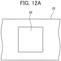
- the operation hole 36 of the embodiment is an oval long hole having its long diameter direction along the front-rear direction; however, the cross-sectional shape of the operation hole 36 is not limited to an oval shape. For example, it may be rectangular as shown in FIG. 12A .
- the operation hole 36 communicates with the long hole 21a of the case body 10, and is exposed to the outside through the long hole 21a.
- the operation hole 36 may not be provided.
- a slit 37 extending in the front-rear direction is provided in the middle of the slide member 35 in the upper-lower direction.
- the rear end portion of the shutter member 30 is configured to be inserted into the slit 37.
- the slit 37 opens at least on the front side of the slide member 35, and does not open on the rear side.
- the slit 37 may open to the left and right sides of the slide member 35.
- the rear end portion of the shutter member 30 is configured to be inserted into the slit 37 from the front end opening 37a of the slit 37.
- the length of the slit 37 in the front-rear direction is preferably about 90% of the length of the slide member 35 in the front-rear direction.
- the length in the front-rear direction of the thick portion 35c between the rear end 37b of the slit 37 and the rear end surface 35b of the slide member 35 is approximately 10% of the length in the front-rear direction of the slide member 35.
- the length of the slit 37 is not limited to this, it is necessary to have a length such that the rear end portion of the sliding shutter member 30 is inserted into the slit 37 and constantly held thereinside.
- the slide member 35 includes a first plate-shaped portion 38 provided below the slit 37, i.e., on an outer side of the slit 37 in the case body 10, and a second plate-shaped portion 39 provided above the slit 37, i.e., on the inner side of the slit 37 in the case body 10, and the first plate-shaped portion 38 and the second plate-shaped portion 39 are integrally provided.
- the rear end portion of the shutter member 30 configured to be inserted into the slit 37 is sandwiched between the lower (the outer side in the case body 10) first plate-shaped portion 38 and the upper (the inner side in the case body 10) second plate-shaped portion 39.
- the slide member 35 is provided in the space 22 so as to be movable in the front-rear direction.
- the front-rear direction refers to the sliding direction of the shutter member 30.
- the slide member 35 is guided by being slid relative to the protruding plate portion 21, the plate portion 26, and the left and right side wall portions 16 of the bottom plate portion 13, and is movable in the front-rear direction.
- the configuration for guiding the slide member 35 in the front-rear direction is not limited thereto.
- flange-shaped plate pieces provided on both side surfaces of the slide member 35 may be inserted into grooves provided on inner surfaces of the side wall portions 16 on both sides to slide.
- a front recessed portion 32a is provided on the upper surface of the slide member 35, that is, on the front end portion of the upper surface of the second plate-shaped portion 39, and a front step portion 32b is provided at the front side of the front recessed portion 32a. Further, a rear recessed portion 33a is provided at the rear end portion of the upper surface of the second plate-shaped portion 39, and a rear step portion 33b is provided at the rear side of the rear recessed portion 33a.
- Each of the front recessed portion 32a and the rear recessed portion 33a has a groove-shaped recessed portion extending in the left-right direction.
- Each of the front step portion 32b and the rear step portion 33b has a protruding strip extending in the left-right direction.
- FIG. 5 shows a state in which the slide member 35 can slide in the front-rear direction between the front protruding portion 26a and the rear protruding portion 26b of the plate portion 26 in the space 22.
- the front step portion 32b comes into contact with the front protruding portion 26a of the plate portion 26, and when the slide member 35 slides further forward, the front protruding portion 26a rides on the front step portion 32b, and then enters and engages with the front recessed portion 32a.
- the slide member 35 shown in FIGS. 1 and 4 shows such a state. With such a configuration, further forward sliding of the slide member 35 is restricted.
- a position at which the front protruding portion 26a of the plate portion 26 is engaged with the front recessed portion 32a may be referred to as a front end position of the slide member 35
- a position at which the rear protruding portion 26b of the plate portion 26 is engaged with the rear recessed portion 33a may be referred to as a rear end position of the slide member 35.
- the rear end portion of the shutter member 30 is inserted into the slit 37 of the slide member 35 from the front end opening 37a.
- the shutter member 30 can slide in the front-rear direction in the slit 37. That is, the shutter member 30 and the slide member 35 can slide in the front-rear direction, which is the sliding direction of the shutter member 30, relative to each other.
- the shutter member 30 and the slide member 35 are independently slidable in the front-rear direction in a non-interlocked or non-conjunction state.
- the first plate-shaped portion 38 of the slide member 35 is provided on the outer side of the shutter member 30 in a superimposed manner, and the second plate-shaped portion 39 is provided on the inner side of the shutter member 30 in a superimposed manner.
- the shutter member 30 when the case 1 is a state of being shipped, the shutter member 30 is slid forward and positioned at a closed position. In the shutter member 30 in the closed position, the opening 31 is provided above the discharge port 19, and the discharge port 19 is closed by a lower portion of the opening 31 in the shutter member 30. As shown in FIG. 7 , when the shutter member 30 closes the discharge port 19, the discharge port 19 is securely closed by providing a closing margin H between the lower end edge 31a of the opening 31 of the shutter member 30 and the upper end edge 19a of the discharge port 19.
- the closing margin H is preferably at least 3.9 mm long.
- the slide member 35 at the time of shipment is provided at the front end position as shown in FIG. 4 .
- a gap G2 is provided between the rear end 30b of the shutter member 30 and the rear end 37b of the slit 37.
- the distance G2 is preferably at least 0.3 mm.
- a gap G1 is provided between the front end 30a of the shutter member 30 and the upper end 41a of the guide slit 41.
- the distance G1 is at least 0.6 mm.
- the shutter member 30 and the slide member 35 can freely slide in the front-rear direction in a state in which they are not in conjunction with each other.
- the slide member 35 is slid rearward in the closed state when the shutter member 30 is shipped, and the slide member 35 is provided at the rear end position, as shown in FIG. 6 , the shutter member 30 does not move, and the discharge port 19 is kept closed by the shutter member 30.
- the rear end portion of the shutter member 30 enters the slit 37 and is held therein. As shown in FIG.
- the length of the rear end portion of the shutter member 30 inserted into the slit 37 at this time that is, the distance L1 between the rear end 30b of the shutter member 30 and the front end opening 37a of the slit 37, is at least 1 mm, because the shutter member 30 is not detached from the slide member 35.
- the opening 31 of the shutter member 30 matches the discharge port 19 and the discharge port 19 is opened.
- a gap G3 is provided between the front end 30a of the shutter member 30 and the upper end 41a of the guide slit 41.
- the distance G3 is preferably about 11.6 mm.
- an operation pin 60 is inserted into the operation hole 36 of the slide member 35, and the shutter member 30 is pierced and penetrated by the operation pin 60.
- the operation pin 60 is moved rearward in the opening direction of the shutter member.
- the slide member 35 and the shutter member 30 are moved together to slide together.
- the opening 31 of the shutter member 30 matches the discharge port 19 that has been closed by the shutter member 30, such that the discharge port 19 is opened.
- the long hole 21a of the case 1 that exposes the operation hole 36 has a length that allows the operation pin 60 to slide until the discharge port 19 opens.
- the shutter member 30 is a film member having a thickness of about 0.1 mm or more and 0.5 mm or less, the shutter member 30 can be easily broken by the pin 60.
- the shutter member 30 is exposed to the outside through the operation hole 36 of the slide member 35 and the long hole 21a of the case body 10, since a flat surface is exposed without a portion such as a hole, a protruding portion, or a recessed portion which may allow the shutter member 30 to be slid easily, it is difficult to slide the shutter member 30 unless making an effort such as piercing by the pin 60.
- the discharge port 19 cannot be easily opened.
- a through hole 30c that communicates with the operation hole 36 may be provided in the shutter member 30 in advance, and the pin 60 may be inserted into the through hole 30c to slide the shutter member 30 to open the discharge port 19 without piercing the shutter member 30. In this case, it is possible to eliminate the effort of piercing the slide member 35 with the pin 60.
- the cross-sectional shape of the operation hole 36 of the slide member 35 may include a complicated shape or a special shape, and only the operation pin corresponding to such a hole shape may be inserted.
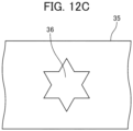
- Examples of such operation holes include an operation hole 36 having a cylindrical cross section as shown in FIG. 12B and an operation hole 36 having a star cross section as shown in FIG. 12C .
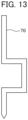
- a crank-shaped operation pin 70 may be used to operate the slide member 35.
- the operation hole 36 when the shutter member 30 is opened, a hole is formed in the slide member 35 using a tool or the like and, moreover, a hole is formed in the shutter member 30 using the operation pin 60 as in the above embodiment. Thereafter, by sliding the slide member 35 and the shutter member 30 rearward using the pin 60, the discharge port 19 can be opened.
- the first plate-shaped portion 38 of the slide member 35 includes the operation hole 36 that exposes the shutter member 30 to the outside.
- the shutter member 30 is a film-shaped member having a thickness of 0.1 mm or more and 0.5 mm or less.
- the shutter member 30 may include the through hole 30c communicable with the operation hole 36.
- the slide member 35 it is preferable for the slide member 35 to include the second plate-shaped portion 39 that sandwiches the shutter member 30 with the first plate-shaped portion 38 and provided on an inner side of the shutter member 30.
- the slide member 35 itself has a function of guiding the slide of the shutter member 30, it is possible to simplify the configuration, and it is also possible to hold the shutter member 30 at a predetermined position by the slide member 35.
- the method of using the case 1 according to the embodiment includes operating the operation pin 60 into the operation hole 36 of the slide member 35, causing the operation pin 60 to pierce the shutter member 30, moving the operation pin 60 in the opening direction of the shutter member 30, and sliding the slide member 35 and the shutter member 30 in conjunction with each other to open the discharge port 19 closed by the shutter member 30.
- the shutter member 30 is inserted into the slit 37 of the slide member 35.
- the shutter member 30 may be superimposed on the upper surface of the slide member 35 so that they can be moved relative to each other.
- a step portion may be provided by providing a protruding portion or a recessed portion on the lower surface of the slide member 35, and the slide member 35 may be slid using the step portion.
Landscapes
- Engineering & Computer Science (AREA)
- Manufacturing & Machinery (AREA)
- Microelectronics & Electronic Packaging (AREA)
- Packaging Of Annular Or Rod-Shaped Articles, Wearing Apparel, Cassettes, Or The Like (AREA)
- Connector Housings Or Holding Contact Members (AREA)
- Supply And Installment Of Electrical Components (AREA)
Abstract
Description
- The present invention relates to a case for accommodating electronic components such as chip components and a method of using the case.
- Conventionally, when mounting electronic components on a substrate, a mounting device for mounting the electronic components at a predetermined position on the substrate is used. It is necessary to supply the electronic components individually to such a mounting device. For example,
Japanese Unexamined Patent Application, Publication No. 2009-295618 - Patent Document 1:
Japanese Unexamined Patent Application, Publication No. 2009-295618 - In this type of case, it may be necessary to reduce or prevent disadvantages such as mixing of different types of electronic components into the case and extraction of an unusual electronic component from the case. For this purpose, a configuration is required in which an opening serving as an inlet/outlet of the electronic components into/from the case cannot be easily opened. However, in the case disclosed in
Japanese Unexamined Patent Application, Publication No. 2009-295618 - An embodiment of the present invention provides a case in which an opening serving as an inlet/outlet port of components into/from the case cannot be easily opened.
- An embodiment of the present application provides a case including: a case body including an accommodation space that accommodates a plurality of components and an opening for taking the plurality of components into and out of the accommodation space; a shutter member that is provided in the case body in a slidable manner and opens and closes the opening by sliding; and a slide member including a first plate-shaped portion that is provided in the case body, slidable relative to the shutter member along a sliding direction of the shutter member, and provided on an outer side of the shutter member in the case body in a superimposable manner, in which, in a state in which the shutter member closes the discharge port, the slide member is superimposed on the shutter member so that the slide member is integrally slidable with the shutter member.
- According to an embodiment of the present invention, it is possible to provide a case in which an opening serving as an inlet/outlet port of components into/from the case cannot be easily opened.
-
-
FIG. 1 is a side view of the inside of a case according to an embodiment of the present invention. -
FIG. 2 is a front view of the case according to the embodiment. -
FIG. 3 is a bottom view of the case according to the embodiment. -
FIG. 4 is an enlarged side view of the inside of the front portion of the case according to the embodiment, showing a state in which a discharge port of the case is closed by a shutter member. -
FIG. 5 is a side cross-sectional view of a configuration of a slide member included in the case according to the embodiment. -
FIG. 6 is an enlarged side view of the inside of the front portion of the case according to the embodiment, showing a state in which a discharge port of the case is opened by a shutter member. -
FIG. 7 is an enlarged side view of the periphery of a front wall portion and the discharge port of the case according to the embodiment, showing a state in which the discharge port of the case is closed by a shutter member. -
FIG. 8A is a side cross-sectional view showing a configurational relationship between a shutter member and a slide member included in the case according to the embodiment, and is a view showing a state closed by the shutter member at the time of shipment. -
FIG. 8B is a side cross-sectional view showing a configuration in which the shutter member included in the case according to the embodiment has a through hole which communicates with an operation hole of the slide member. -
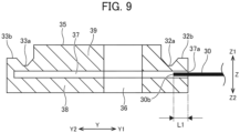
FIG. 9 is a side cross-sectional view showing a configurational relationship between a shutter member and a slide member included in the case according to the embodiment, and shows a state closed by the shutter member and in which the slide member slides rearwardly. -
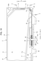
FIG. 10 is an enlarged side view of the inside of the front portion of the case according to the embodiment, and shows an example of a use method when the discharge port of the case is opened. -
FIG. 11 is an enlarged side view of the periphery of the front wall portion and the discharge port of the case according to the embodiment, and shows a state in which the discharge port of the case is open. -
FIG. 12A is a view of another example of the shape of the operation hole provided in the slide member included in the case according to the embodiment, and shows a rectangular operation hole. -
FIG. 12B is a view of another example of the shape of the operation hole provided in the slide member included in the case according to the embodiment, and shows a cylindrical operation hole. -
FIG. 12C is a view of another example of the shape of the operation hole provided in the slide member included in the case according to the embodiment, and shows an operation hole having a star shape. -
FIG. 13 is a side view of an example of a pin for sliding the slide member included in the case according to the embodiment. - Hereinafter, embodiments of the present invention will be described.
-
FIG. 1 is a side view of the inside of a case 1 according to an embodiment,FIG. 2 is a front view of the case 1 viewed from the front, andFIG. 3 is a bottom view of the case 1.FIG. 4 is an enlarged side view showing the inside of the front portion of the case 1. - As shown in
FIG. 1 , the case 1 accommodates therein a plurality of electronic components M as components in a loose state. The case 1 accommodating a plurality of electronic components M is set in a feeder (not shown), and the electronic components M are discharged from the case 1 by vibration of the feeder and supplied to a mounting device or the like. Each of the electronic components M of the present embodiment is, for example, a small rectangular parallelepiped electronic component having a length of 1.2 mm or less in the longitudinal direction. Examples of such electronic components include capacitors and inductors, but the present embodiment is not limited thereto. - The arrows X, Y, and Z shown in any one of
FIGS. 1 ,2 , and3 respectively indicate the left-right direction, the front-rear direction, and the upper-lower direction of the case 1 when the case 1 is set in the feeder. Further, the left side in the left-right direction X is denoted by X1, the right side is denoted by X2, the front side in the front-rear direction Y is denoted by Y1, the rear side is denoted by Y2, the upper side in the upper-lower direction Z is denoted by Z1, and the lower side is denoted by Z2. InFIGS. 4 to 11 , any one of the left-right direction X, the longitudinal direction Y, and the upper-lower direction Z is similarly applied. The left-right direction, the front-rear direction, and the upper-lower direction in the following description are based on the directions indicated by the arrows. - As shown in
FIG. 1 , the case 1 includes acase body 10 that accommodates a plurality of electronic components M, ashutter member 30 that opens and closes adischarge port 19 of thecase body 10, and aslide member 35 that is operated to slide theshutter member 30. Thedischarge port 19 is an example of an opening. - As shown in
FIGS. 2 and3 , thecase body 10 are divided into thefirst member 2 and thesecond member 3 as left and right portions. Thefirst member 2 and thesecond member 3 are joined to each other to provide thecase body 10. -
FIG. 1 shows the interior of thesecond member 3 on the right side without thefirst member 2 on the left side. Thecase body 10 has a flat box shape that is long in the front-rear direction and thin in the left-right direction. In the following description, except where necessary, thefirst member 2 and thesecond member 3 are not individually described, and a configuration in which thefirst member 2 and thesecond member 3 are joined to each other will be described. - The
case body 10 includes anaccommodation space 11 for accommodating the plurality of electronic components M in a loose state. Thecase body 10 includes atop plate portion 12 and abottom plate portion 13 which extend in the front-rear direction, afront wall portion 14 and arear wall portion 15 which extend in the upper-lower direction, a pair of left and rightside wall portions 16, and asloped plate portion 17 which partitions the interior of thecase body 10 vertically. Therear wall portion 15 includes an outerrear wall portion 15a functioning as an outer surface and an innerrear wall portion 15b in front of the outer rear wall portion. - The
discharge port 19 is an opening for taking the electronic components M into and out of theaccommodation space 11. Thedischarge port 19 is provided at the lower portion of thefront wall portion 14. As shown inFIG. 2 , thedischarge port 19 has a rectangular shape. The shape of thedischarge port 19 is not limited to a rectangular shape, and thedischarge port 19 may include, for example, an opening having a circular shape, an elliptical shape, or the like. Thedischarge port 19 is opened and closed by theshutter member 30 described later.FIG. 1 shows the case 1 in a shipped state in which a predetermined number of electronic components M are accommodated in theaccommodation space 11 and thedischarge port 19 is closed by theshutter member 30. - The sloped
plate portion 17 extends between the left and rightside wall portions 16 and extends from the innerrear wall portion 15b to the lower portion of thedischarge port 19. The slopedplate portion 17 is provided below the center of thecase body 10 in the upper-lower direction in thecase body 10. In thecase body 10, the upper side of the slopedplate portion 17 functions as theaccommodation space 11, and the lower side of the slopedplate portion 17 functions as thelower space 18. - The sloped
plate portion 17 is sloped at a downward gradient toward thedischarge port 19, and an upper surface of the slopedplate portion 17 includes asloped surface 17a that is sloped at a downward gradient toward thedischarge port 19. In the present embodiment, the slope angle θ1 of the slopedsurface 17a is about 10° with respect to the horizontal direction when the case 1 is set in the feeder. The slope angle θ1 of the slopedsurface 17a is preferably 3° or more and 10° or less.
The slope angle θ1 of the slopedsurface 17a is appropriately adjusted according to the vibration condition of the feeder. - As shown in
FIG. 1 , anRFID tag 27 having an elongated band shape in the front-rear direction is provided at a rear portion of thelower space 18. TheRFID tag 27 has a stickerlike shape and property, and attached to the upper surface of thebottom plate portion 13. TheRFID tag 27 has a known configuration including a transmission/reception unit, memory, an antenna, and the like. For example, a reader/writer that reads and writes information from and to theRFID tag 27 is provided in the feeder in which the case 1 is set. - The
case body 10 includes anupper grip portion 28A and arear grip portion 28B.
Theupper grip portions 28A are a pair of front and rear recesses provided at both front and rear ends of the upper side of thecase body 10. Therear grip portions 28B are a pair of upper and lower recesses respectively provided at the upper and lower ends of the rear side of thecase body 10. Each of theupper grip portions 28A and therear grip portions 28B is gripped by a robot hand, for example, when the case 1 is carried by the robot hand. - As shown in
FIG. 1 , thecase body 10 includes a plurality of claw portions on the bottom surface for detachably setting thecase body 10 in the feeder. In the present embodiment, afirst claw portion 61, asecond claw portion 62, and athird claw portion 63 are provided on the bottom surface at intervals in the front-rear direction. Thefirst claw portion 61, thesecond claw portion 62, and thethird claw portion 63 are provided integrally with thecase body 10. Each of thefirst claw portion 61 and thesecond claw portion 62 includes a T-shaped slot having an inverted T-shape in a cross section in a plane extending in the up, down, left, and right directions. Thethird claw portion 63 is an L-shaped plate piece extending rearward in a side view. - The
shutter member 30 slides to open and close thedischarge port 19. Theshutter member 30 continuously extends from thebottom plate portion 13 to thefront wall portion 14, and is slidable along the extending direction. Theshutter member 30 is an elongated band-shaped film member. Theshutter member 30 is made of a flexible material having a certain degree of rigidity and is bendable, such as PET(Polyethylene terephthalate). The thickness of theshutter member 30 made of such a film-shaped member is not limited, but is preferably, for example, 0.1 mm or more and 0.5 mm or less. The width of theshutter member 30 is slightly larger than the width of thedischarge port 19, and has a width capable of covering thedischarge port 19 without a gap. As shown inFIGS. 1 and2 , anopening 31 having substantially the same shape as thedischarge port 19 is provided in the front end portion of theshutter member 30. - The
shutter member 30 can slide along thelower guide portion 5 and theupper guide portion 4 of thecase body 10. Thelower guide portion 5 is provided above thebottom plate portion 13, and theupper guide portion 4 is provided above thedischarge port 19. The rear side of theshutter member 30 slides substantially horizontally along thelower guide portion 5, and the front side of theshutter member 30 slides vertically along theupper guide portion 4. Each of thelower guide portion 5 and theupper guide portion 4 provides a passage for slidably holding theshutter member 30 while maintaining the surface direction of theshutter member 30 along the left-right direction. - As shown in
FIG. 4 , thelower guide portion 5 includes a firstlower guide portion 51 provided below thedischarge port 19 and a secondlower guide portion 52 provided behind the firstlower guide portion 51. - The second
lower guide portion 52 is configured by a gap provided between thebottom plate portion 13 and the protrudingportion 17c protruding downward at the front end portion of the slopedplate portion 17. The firstlower guide portion 51 includes afront end surface 17b of the slopedplate portion 17 and afront end portion 29 of thebottom plate portion 13. - The rear portion of the
shutter member 30 passes through the gap between the protrudingportion 17c and thebottom plate portion 13 in the secondlower guide portion 52. With such a configuration, the rear portion of theshutter member 30 slides in the front-rear direction immediately above thebottom plate portion 13. In the firstlower guide portion 51, theshutter member 30 slides along thefront end portion 29 of thebottom plate portion 13 which curves in a recessed manner in the front-rear direction, and further slides along thefront end surface 17b of the slopedplate portion 17, whereby theshutter member 30 bends upward at an angle of approximately 90° from the horizontal direction, and turns into a posture extending in the upper-lower direction. - As shown in
FIG. 4 , theupper guide portion 4 includes a guide slit 41 provided in thefront wall portion 14 and extending in the upper-lower direction. The front end portion of theshutter member 30 is inserted into the guide slit 41 from the lower end of thefront wall portion 14, and slides in the upper-lower direction in the guide slit 41. - The
slide member 35 slides theshutter member 30 to open and close thedischarge port 19. As shown inFIGS. 1 and4 , aslide member 35 is provided at the rear end of theshutter member 30. - As shown in
FIG. 4 , thebottom plate portion 13 of thecase body 10 has a protrudingplate portion 21 on the front side thereof. The protrudingplate portion 21 protrudes downward and extends in the front-rear direction. The protrudingplate portion 21 is provided with along hole 21a extending in the front-rear direction. Aplate portion 26 is provided above the protrudingplate portion 21 with apredetermined space 22 therebetween. Theplate portion 26 is substantially parallel to the protrudingplate portion 21, and is provided integrally with thebottom plate portion 13. Thespace 22 is surrounded by the protrudingplate portion 21, theplate portion 26, and the left and rightside wall portions 16. Theslide member 35 is provided in thespace 22. A front protrudingportion 26a protruding downward is provided at the front end portion of theplate portion 26. A rear protrudingportion 26b protruding downward is provided at the rear end portion of theplate portion 26. - The
slide member 35 is a rectangular plate piece elongated in the front-rear direction. Anoperation hole 36 penetrating in the upper-lower direction is provided in theslide member 35. As shown inFIG. 3 , theoperation hole 36 of the embodiment is an oval long hole having its long diameter direction along the front-rear direction; however, the cross-sectional shape of theoperation hole 36 is not limited to an oval shape. For example, it may be rectangular as shown inFIG. 12A . Theoperation hole 36 communicates with thelong hole 21a of thecase body 10, and is exposed to the outside through thelong hole 21a. - The
operation hole 36 may not be provided. - As shown in
FIG. 5 , aslit 37 extending in the front-rear direction is provided in the middle of theslide member 35 in the upper-lower direction. The rear end portion of theshutter member 30 is configured to be inserted into theslit 37. Theslit 37 opens at least on the front side of theslide member 35, and does not open on the rear side. Theslit 37 may open to the left and right sides of theslide member 35. The rear end portion of theshutter member 30 is configured to be inserted into theslit 37 from the front end opening 37a of theslit 37. - The length of the
slit 37 in the front-rear direction is preferably about 90% of the length of theslide member 35 in the front-rear direction. In this case, the length in the front-rear direction of thethick portion 35c between therear end 37b of theslit 37 and therear end surface 35b of theslide member 35 is approximately 10% of the length in the front-rear direction of theslide member 35. Although the length of theslit 37 is not limited to this, it is necessary to have a length such that the rear end portion of the slidingshutter member 30 is inserted into theslit 37 and constantly held thereinside. - The
slide member 35 includes a first plate-shapedportion 38 provided below theslit 37, i.e., on an outer side of theslit 37 in thecase body 10, and a second plate-shapedportion 39 provided above theslit 37, i.e., on the inner side of theslit 37 in thecase body 10, and the first plate-shapedportion 38 and the second plate-shapedportion 39 are integrally provided. The rear end portion of theshutter member 30 configured to be inserted into theslit 37 is sandwiched between the lower (the outer side in the case body 10) first plate-shapedportion 38 and the upper (the inner side in the case body 10) second plate-shapedportion 39. - The
slide member 35 is provided in thespace 22 so as to be movable in the front-rear direction. Here, the front-rear direction refers to the sliding direction of theshutter member 30. Theslide member 35 is guided by being slid relative to the protrudingplate portion 21, theplate portion 26, and the left and rightside wall portions 16 of thebottom plate portion 13, and is movable in the front-rear direction. The configuration for guiding theslide member 35 in the front-rear direction is not limited thereto. For example, flange-shaped plate pieces provided on both side surfaces of theslide member 35 may be inserted into grooves provided on inner surfaces of theside wall portions 16 on both sides to slide. - A front recessed
portion 32a is provided on the upper surface of theslide member 35, that is, on the front end portion of the upper surface of the second plate-shapedportion 39, and afront step portion 32b is provided at the front side of the front recessedportion 32a. Further, a rear recessedportion 33a is provided at the rear end portion of the upper surface of the second plate-shapedportion 39, and arear step portion 33b is provided at the rear side of the rear recessedportion 33a. Each of the front recessedportion 32a and the rear recessedportion 33a has a groove-shaped recessed portion extending in the left-right direction. Each of thefront step portion 32b and therear step portion 33b has a protruding strip extending in the left-right direction. -
FIG. 5 shows a state in which theslide member 35 can slide in the front-rear direction between the front protrudingportion 26a and the rear protrudingportion 26b of theplate portion 26 in thespace 22. When theslide member 35 slides forward from this state, thefront step portion 32b comes into contact with the front protrudingportion 26a of theplate portion 26, and when theslide member 35 slides further forward, thefront protruding portion 26a rides on thefront step portion 32b, and then enters and engages with the front recessedportion 32a. Theslide member 35 shown inFIGS. 1 and4 shows such a state. With such a configuration, further forward sliding of theslide member 35 is restricted. - On the other hand, when the
slide member 35 slides rearward, therear step portion 33b comes into contact with the rear protrudingportion 26b of theplate portion 26, and when further slides rearward, therear protruding portion 26b rides on therear step portion 33b and then enters and engages with the rear recessedportion 33a. Theslide member 35 shown inFIG. 6 shows such a state. With such a configuration, further rearward sliding of theslide member 35 is restricted. - In this way, in both the case where the
front protruding portion 26a of theplate portion 26 engages with the front recessedportion 32a of theslide member 35 and the case where therear protruding portion 26b of theplate portion 26 engages with the rear recessedportion 33a of theslide member 35, it is possible for the operator who slides theslide member 35 to experience a click feeling. In the following description, a position at which thefront protruding portion 26a of theplate portion 26 is engaged with the front recessedportion 32a may be referred to as a front end position of theslide member 35, and a position at which therear protruding portion 26b of theplate portion 26 is engaged with the rear recessedportion 33a may be referred to as a rear end position of theslide member 35. - As described above, the rear end portion of the
shutter member 30 is inserted into theslit 37 of theslide member 35 from thefront end opening 37a. Theshutter member 30 can slide in the front-rear direction in theslit 37. That is, theshutter member 30 and theslide member 35 can slide in the front-rear direction, which is the sliding direction of theshutter member 30, relative to each other. In other words, theshutter member 30 and theslide member 35 are independently slidable in the front-rear direction in a non-interlocked or non-conjunction state. When theshutter member 30 is inserted into theslit 37, the first plate-shapedportion 38 of theslide member 35 is provided on the outer side of theshutter member 30 in a superimposed manner, and the second plate-shapedportion 39 is provided on the inner side of theshutter member 30 in a superimposed manner. - As shown in
FIGS. 1 and4 , when the case 1 is a state of being shipped, theshutter member 30 is slid forward and positioned at a closed position. In theshutter member 30 in the closed position, theopening 31 is provided above thedischarge port 19, and thedischarge port 19 is closed by a lower portion of theopening 31 in theshutter member 30. As shown inFIG. 7 , when theshutter member 30 closes thedischarge port 19, thedischarge port 19 is securely closed by providing a closing margin H between thelower end edge 31a of theopening 31 of theshutter member 30 and theupper end edge 19a of thedischarge port 19. The closing margin H is preferably at least 3.9 mm long. - In addition, the
slide member 35 at the time of shipment is provided at the front end position as shown inFIG. 4 . At this time, as shown inFIG. 8A , a gap G2 is provided between therear end 30b of theshutter member 30 and therear end 37b of theslit 37. The distance G2 is preferably at least 0.3 mm. With such a configuration, it is possible to reduce or prevent deformation of theshutter member 30 due to contact with theslide member 35. At this time, as shown inFIG. 4 , theshutter member 30, and the first plate-shapedportion 38 and the second plate-shapedportion 39 of theslide member 35 are superimposed with each other. Further, as shown inFIG. 7 , a gap G1 is provided between thefront end 30a of theshutter member 30 and theupper end 41a of the guide slit 41. The distance G1 is at least 0.6 mm. With such a configuration, it is possible to reduce or prevent deformation of theshutter member 30 due to contact with thecase body 10. - As described above, the
shutter member 30 and theslide member 35 can freely slide in the front-rear direction in a state in which they are not in conjunction with each other. Here, in a case where theslide member 35 is slid rearward in the closed state when theshutter member 30 is shipped, and theslide member 35 is provided at the rear end position, as shown inFIG. 6 , theshutter member 30 does not move, and thedischarge port 19 is kept closed by theshutter member 30. At this time, the rear end portion of theshutter member 30 enters theslit 37 and is held therein. As shown inFIG. 9 , it is preferable that the length of the rear end portion of theshutter member 30 inserted into theslit 37 at this time, that is, the distance L1 between therear end 30b of theshutter member 30 and the front end opening 37a of theslit 37, is at least 1 mm, because theshutter member 30 is not detached from theslide member 35. - Here, in a state where both the
shutter member 30 and theslide member 35 are shipped, when both theshutter member 30 and theslide member 35 are in conjunction with each other to slide theslide member 35 to the rear end position, as shown inFIG. 10 , theopening 31 of theshutter member 30 matches thedischarge port 19 and thedischarge port 19 is opened. When thedischarge port 19 is opened in this manner, as shown inFIG. 11 , a gap G3 is provided between thefront end 30a of theshutter member 30 and theupper end 41a of the guide slit 41. The distance G3 is preferably about 11.6 mm. - It is possible for a user who has received the supply of the case 1 according to the embodiment having the above configuration to perform, for example, an opening operation of opening the
shutter member 30 in a state at the time of shipment in the following manner. - As shown in
FIG. 10 , anoperation pin 60 is inserted into theoperation hole 36 of theslide member 35, and theshutter member 30 is pierced and penetrated by theoperation pin 60. Theoperation pin 60 is moved rearward in the opening direction of the shutter member. With such a configuration, theslide member 35 and theshutter member 30 are moved together to slide together. When theslide member 35 is slid to the rear end position, theopening 31 of theshutter member 30 matches thedischarge port 19 that has been closed by theshutter member 30, such that thedischarge port 19 is opened. Thelong hole 21a of the case 1 that exposes theoperation hole 36 has a length that allows theoperation pin 60 to slide until thedischarge port 19 opens. - In a case where the
shutter member 30 is a film member having a thickness of about 0.1 mm or more and 0.5 mm or less, theshutter member 30 can be easily broken by thepin 60. Although theshutter member 30 is exposed to the outside through theoperation hole 36 of theslide member 35 and thelong hole 21a of thecase body 10, since a flat surface is exposed without a portion such as a hole, a protruding portion, or a recessed portion which may allow theshutter member 30 to be slid easily, it is difficult to slide theshutter member 30 unless making an effort such as piercing by thepin 60. According to the case 1 of the embodiment, by making it difficult to operate theshutter member 30, thedischarge port 19 cannot be easily opened. - As shown in
FIG. 8B , a throughhole 30c that communicates with theoperation hole 36 may be provided in theshutter member 30 in advance, and thepin 60 may be inserted into the throughhole 30c to slide theshutter member 30 to open thedischarge port 19 without piercing theshutter member 30. In this case, it is possible to eliminate the effort of piercing theslide member 35 with thepin 60. - In order to make it difficult to operate the
shutter member 30, the cross-sectional shape of theoperation hole 36 of theslide member 35 may include a complicated shape or a special shape, and only the operation pin corresponding to such a hole shape may be inserted. Examples of such operation holes include anoperation hole 36 having a cylindrical cross section as shown inFIG. 12B and anoperation hole 36 having a star cross section as shown inFIG. 12C . - Conversely, it is also possible to make it difficult to operate the
shutter member 30 even by using a means in which theslide member 35 can be slid only by an operation pin having a special shape. For example, as shown inFIG. 13 , a crank-shapedoperation pin 70 may be used to operate theslide member 35. - According to the case 1 according to the embodiment described above, the following effects are achieved.
-
- (1) The case 1 according to the embodiment includes the
case body 10 including theaccommodation space 11 that accommodates the plurality of components M and thedischarge port 19 functioning as an opening for taking the plurality of components M into and out of theaccommodation space 11, theshutter member 30 that is provided in thecase body 10 in a slidable manner and opens and closes thedischarge port 19 by sliding, and theslide member 35 including the first plate-shapedportion 38 that is provided in thecase body 10, slidable relative to theshutter member 30 along the sliding direction of theshutter member 30, and provided on the outer side of theshutter member 30 in thecase body 10 in a superimposable manner. In a state in which theshutter member 30 closes thedischarge port 19, theslide member 35 is superimposed on theshutter member 30 so that theslide member 35 is integrally slidable with theshutter member 30. - With such a configuration, even when the
slide member 35 including the first plate-shaped portion which is superimposed on theshutter member 30 is slid, theshutter member 30 cannot be slid and, therefore, thedischarge port 19 cannot be easily opened. As a result, it is possible to effectively reduce or prevent disadvantages such as mixing of different kinds of electronic components M into the case 1 and extraction of an unusual electronic component M from the case 1. - When the
operation hole 36 is not provided in theslide member 35, theslide member 35 cannot be easily slid, so that it is possible to further ensure the closed state of thedischarge port 19 by theshutter member 30. - Further, in the embodiment in which the
operation hole 36 is not provided in theslide member 35, when theshutter member 30 is opened, a hole is formed in theslide member 35 using a tool or the like and, moreover, a hole is formed in theshutter member 30 using theoperation pin 60 as in the above embodiment. Thereafter, by sliding theslide member 35 and theshutter member 30 rearward using thepin 60, thedischarge port 19 can be opened. - (2) In the case 1 according to the embodiment, it is preferable that the first plate-shaped
portion 38 of theslide member 35 includes theoperation hole 36 that exposes theshutter member 30 to the outside. - With such a configuration, it is possible to form a hole in the
shutter member 30 through theoperation hole 36, and it is also possible to easily and accurately perform the opening operation of sliding theslide member 35 and theshutter member 30 in conjunction with each other by theoperation pin 60. - (3) In the case 1 according to the embodiment, it is preferable that the
shutter member 30 is a film-shaped member having a thickness of 0.1 mm or more and 0.5 mm or less. - With such a configuration, it is possible to easily break the
shutter member 30 by theoperation pin 60, and it is possible to smoothly operate the opening operation. - (4) In the case 1 according to the embodiment, the
shutter member 30 may include the throughhole 30c communicable with theoperation hole 36. - With such a configuration, it is possible to cause the
operation pin 60 to be passed through theshutter member 30 and to allow theshutter member 30 to be easily integrated with theslide member 35 without breaking theshutter member 30, such that it is possible to smoothly perform the opening operation of theshutter member 30. - (5) In the case 1 according to the embodiment, it is preferable for the
slide member 35 to include the second plate-shapedportion 39 that sandwiches theshutter member 30 with the first plate-shapedportion 38 and provided on an inner side of theshutter member 30. - With such a configuration, since the
slide member 35 itself has a function of guiding the slide of theshutter member 30, it is possible to simplify the configuration, and it is also possible to hold theshutter member 30 at a predetermined position by theslide member 35. - (6) The method of using the case 1 according to the embodiment includes operating the
operation pin 60 into theoperation hole 36 of theslide member 35, causing theoperation pin 60 to pierce theshutter member 30, moving theoperation pin 60 in the opening direction of theshutter member 30, and sliding theslide member 35 and theshutter member 30 in conjunction with each other to open thedischarge port 19 closed by theshutter member 30. - With such a configuration, it is possible to easily and accurately perform the opening operation of sliding the
slide member 35 and theshutter member 30 in conjunction with each other by theoperation pin 60. - Although embodiments have been described above, the present invention is not limited to these embodiments, and modifications, improvements, and the like within the scope of achieving the object of the present invention are included in the present invention.
- For example, the
shutter member 30 is inserted into theslit 37 of theslide member 35. However, theshutter member 30 may be superimposed on the upper surface of theslide member 35 so that they can be moved relative to each other. - Further, a step portion may be provided by providing a protruding portion or a recessed portion on the lower surface of the
slide member 35, and theslide member 35 may be slid using the step portion. -
- 1 case
- 10 case body
- 11 accommodation space
- 19 discharge port (opening)
- 30 shutter member
- 30c through hole
- 35 slide member
- 36 operation hole
- 38 first plate-shaped portion
- 39 second plate-shaped portion
- 60 operation pin
- M electronic components (components)
Claims (6)
- A case comprising:a case body including an accommodation space that accommodates a plurality of components and an opening for taking the plurality of components into and out of the accommodation space;a shutter member that is provided in the case body in a slidable manner and opens and closes the opening by sliding; anda slide member including a first plate-shaped portion that is provided in the case body, slidable relative to the shutter member along a sliding direction of the shutter member, and provided on an outer side of the shutter member in the case body in a superimposable manner,wherein, in a state in which the shutter member closes the opening, the slide member is superimposed on the shutter member so that the slide member is integrally slidable with the shutter member.
- The case according to claim 1, wherein the first plate-shaped portion of the slide member includes an operation hole that exposes the shutter member to outside.
- The case according to claim 1 or 2, wherein the shutter member is a film-shaped member having a thickness of 0.1 mm or more and 0.5 mm or less.
- The case according to claim 2, wherein the shutter member includes a through hole communicable with the operation hole.
- The case according to any one of claims 1 to 4, wherein the slide member includes a second plate-shaped member that sandwiches the shutter member with the first plate-shaped member and provided on an inner side of the shutter member.
- A method of using a case according to claim 2, the method comprising:operating an operation pin into the operation hole;causing the operation pin to pierce the shutter member;moving the operation pin in an opening direction of the shutter member; andsliding the slide member and the shutter member in conjunction with each other to open the opening closed by the shutter member.
Applications Claiming Priority (2)
| Application Number | Priority Date | Filing Date | Title |
|---|---|---|---|
| JP2021083810 | 2021-05-18 | ||
| PCT/JP2022/016812 WO2022244537A1 (en) | 2021-05-18 | 2022-03-31 | Case and method for using same |
Publications (2)
| Publication Number | Publication Date |
|---|---|
| EP4344374A1 true EP4344374A1 (en) | 2024-03-27 |
| EP4344374A4 EP4344374A4 (en) | 2025-05-21 |
Family
ID=84141273
Family Applications (1)
| Application Number | Title | Priority Date | Filing Date |
|---|---|---|---|
| EP22804453.3A Pending EP4344374A4 (en) | 2021-05-18 | 2022-03-31 | Case and method for using same |
Country Status (6)
| Country | Link |
|---|---|
| US (1) | US20240074130A1 (en) |
| EP (1) | EP4344374A4 (en) |
| JP (1) | JP7574921B2 (en) |
| KR (1) | KR102795834B1 (en) |
| CN (1) | CN117178646A (en) |
| WO (1) | WO2022244537A1 (en) |
Family Cites Families (14)
| Publication number | Priority date | Publication date | Assignee | Title |
|---|---|---|---|---|
| JPH08167792A (en) * | 1994-12-09 | 1996-06-25 | Sony Corp | Bulk case |
| JPH08336730A (en) * | 1995-06-06 | 1996-12-24 | Sony Corp | Chip parts supply case |
| JPH09283987A (en) * | 1996-04-12 | 1997-10-31 | Sony Corp | Shutter device for bulk case |
| JP3436700B2 (en) | 1998-11-20 | 2003-08-11 | シャープ株式会社 | Bulk case |
| JP2001088943A (en) * | 1999-09-17 | 2001-04-03 | Kawata Mfg Co Ltd | Slide gate |
| JP3624844B2 (en) * | 2001-03-19 | 2005-03-02 | 株式会社村田製作所 | Electronic component chip storage cassette |
| JP3876693B2 (en) * | 2001-11-19 | 2007-02-07 | 株式会社村田製作所 | Electronic component erroneous supply prevention device and electronic component supply device |
| US7359765B2 (en) * | 2004-09-15 | 2008-04-15 | Varvarelis Nicholas M | Electronic pill dispenser |
| JP5054616B2 (en) | 2008-06-02 | 2012-10-24 | 太陽誘電株式会社 | Parts replenishment system for bulk feeder |
| JP2012070861A (en) | 2010-09-28 | 2012-04-12 | Glory Ltd | Game medium counting device |
| JP2012191064A (en) | 2011-03-11 | 2012-10-04 | Du Pont Mitsui Polychem Co Ltd | Electronic component housing case for bulk feeder |
| US9481504B2 (en) * | 2014-05-13 | 2016-11-01 | Walter David Dial, III | Pet toy dispenser and method |
| US9283150B2 (en) * | 2014-06-02 | 2016-03-15 | HB Clouds LLC | Pill dispensing system |
| WO2019060133A1 (en) * | 2017-09-22 | 2019-03-28 | Gumfriend International Corporation | Dispensing container |
-
2022
- 2022-03-31 WO PCT/JP2022/016812 patent/WO2022244537A1/en not_active Ceased
- 2022-03-31 CN CN202280030035.2A patent/CN117178646A/en active Pending
- 2022-03-31 JP JP2023522321A patent/JP7574921B2/en active Active
- 2022-03-31 EP EP22804453.3A patent/EP4344374A4/en active Pending
- 2022-03-31 KR KR1020237038690A patent/KR102795834B1/en active Active
-
2023
- 2023-11-06 US US18/387,105 patent/US20240074130A1/en active Pending
Also Published As
| Publication number | Publication date |
|---|---|
| WO2022244537A1 (en) | 2022-11-24 |
| EP4344374A4 (en) | 2025-05-21 |
| CN117178646A (en) | 2023-12-05 |
| JPWO2022244537A1 (en) | 2022-11-24 |
| JP7574921B2 (en) | 2024-10-29 |
| KR102795834B1 (en) | 2025-04-16 |
| US20240074130A1 (en) | 2024-02-29 |
| KR20230170720A (en) | 2023-12-19 |
Similar Documents
| Publication | Publication Date | Title |
|---|---|---|
| KR102801109B1 (en) | case | |
| CN105932461B (en) | Socket connector | |
| JP7416326B2 (en) | Case | |
| US7300291B2 (en) | Card connector adapted for cards having different width dimensions | |
| US20240244811A1 (en) | Case | |
| US20240074130A1 (en) | Case and method of using the case | |
| EP4181646A1 (en) | Storage case | |
| KR102870436B1 (en) | Cases and seals | |
| EP4400447A1 (en) | Case | |
| US12604450B2 (en) | Case | |
| KR102962243B1 (en) | case | |
| US20240244810A1 (en) | Case | |
| WO2025169610A1 (en) | Storage case | |
| WO2025142040A1 (en) | Component accommodating container, and component accommodating container containing components | |
| JP2009135030A (en) | Memory card connector | |
| JPH09112510A (en) | Clip pinching device | |
| JPH1131271A (en) | Product storage device for automatic vending machine | |
| JPWO2018123060A1 (en) | Printing device | |
| JPH10109796A (en) | Pin tractor cover | |
| JP2014121531A (en) | Game machine |
Legal Events
| Date | Code | Title | Description |
|---|---|---|---|
| STAA | Information on the status of an ep patent application or granted ep patent |
Free format text: STATUS: THE INTERNATIONAL PUBLICATION HAS BEEN MADE |
|
| PUAI | Public reference made under article 153(3) epc to a published international application that has entered the european phase |
Free format text: ORIGINAL CODE: 0009012 |
|
| STAA | Information on the status of an ep patent application or granted ep patent |
Free format text: STATUS: REQUEST FOR EXAMINATION WAS MADE |
|
| 17P | Request for examination filed |
Effective date: 20231106 |
|
| AK | Designated contracting states |
Kind code of ref document: A1 Designated state(s): AL AT BE BG CH CY CZ DE DK EE ES FI FR GB GR HR HU IE IS IT LI LT LU LV MC MK MT NL NO PL PT RO RS SE SI SK SM TR |
|
| DAV | Request for validation of the european patent (deleted) | ||
| DAX | Request for extension of the european patent (deleted) | ||
| A4 | Supplementary search report drawn up and despatched |
Effective date: 20250424 |
|
| RIC1 | Information provided on ipc code assigned before grant |
Ipc: H05K 13/04 20060101ALI20250416BHEP Ipc: H05K 13/00 20060101ALI20250416BHEP Ipc: H05K 13/02 20060101AFI20250416BHEP |