EP4344075A1 - Control method and wireless communication system - Google Patents
Control method and wireless communication system Download PDFInfo
- Publication number
- EP4344075A1 EP4344075A1 EP21940656.8A EP21940656A EP4344075A1 EP 4344075 A1 EP4344075 A1 EP 4344075A1 EP 21940656 A EP21940656 A EP 21940656A EP 4344075 A1 EP4344075 A1 EP 4344075A1
- Authority
- EP
- European Patent Office
- Prior art keywords
- signal processing
- processing unit
- distributed antenna
- wireless communication
- unit
- Prior art date
- Legal status (The legal status is an assumption and is not a legal conclusion. Google has not performed a legal analysis and makes no representation as to the accuracy of the status listed.)
- Pending
Links
Images




Classifications
-
- H—ELECTRICITY
- H04—ELECTRIC COMMUNICATION TECHNIQUE
- H04B—TRANSMISSION
- H04B7/00—Radio transmission systems, i.e. using radiation field
- H04B7/02—Diversity systems; Multi-antenna system, i.e. transmission or reception using multiple antennas
- H04B7/022—Site diversity; Macro-diversity
- H04B7/024—Co-operative use of antennas of several sites, e.g. in co-ordinated multipoint or co-operative multiple-input multiple-output [MIMO] systems
-
- H—ELECTRICITY
- H04—ELECTRIC COMMUNICATION TECHNIQUE
- H04W—WIRELESS COMMUNICATION NETWORKS
- H04W28/00—Network traffic management; Network resource management
- H04W28/02—Traffic management, e.g. flow control or congestion control
- H04W28/08—Load balancing or load distribution
-
- H—ELECTRICITY
- H04—ELECTRIC COMMUNICATION TECHNIQUE
- H04W—WIRELESS COMMUNICATION NETWORKS
- H04W28/00—Network traffic management; Network resource management
- H04W28/16—Central resource management; Negotiation of resources or communication parameters, e.g. negotiating bandwidth or QoS [Quality of Service]
- H04W28/18—Negotiating wireless communication parameters
-
- H—ELECTRICITY
- H04—ELECTRIC COMMUNICATION TECHNIQUE
- H04W—WIRELESS COMMUNICATION NETWORKS
- H04W88/00—Devices specially adapted for wireless communication networks, e.g. terminals, base stations or access point devices
- H04W88/08—Access point devices
- H04W88/085—Access point devices with remote components
-
- Y—GENERAL TAGGING OF NEW TECHNOLOGICAL DEVELOPMENTS; GENERAL TAGGING OF CROSS-SECTIONAL TECHNOLOGIES SPANNING OVER SEVERAL SECTIONS OF THE IPC; TECHNICAL SUBJECTS COVERED BY FORMER USPC CROSS-REFERENCE ART COLLECTIONS [XRACs] AND DIGESTS
- Y02—TECHNOLOGIES OR APPLICATIONS FOR MITIGATION OR ADAPTATION AGAINST CLIMATE CHANGE
- Y02D—CLIMATE CHANGE MITIGATION TECHNOLOGIES IN INFORMATION AND COMMUNICATION TECHNOLOGIES [ICT], I.E. INFORMATION AND COMMUNICATION TECHNOLOGIES AIMING AT THE REDUCTION OF THEIR OWN ENERGY USE
- Y02D30/00—Reducing energy consumption in communication networks
- Y02D30/70—Reducing energy consumption in communication networks in wireless communication networks
Definitions
- the present invention relates to a technology of a control method and a wireless communication system.
- a high frequency band of a millimeter wave band is used, and use of a further higher frequency band capable of securing a wider bandwidth is assumed in order to achieve further increase in speed and capacity in a future wireless system such as the 6G.
- a high frequency band is known to have a large propagation loss and high straightness, and a distributed antenna system has been studied in order to improve connectivity in covering a communication area (see Non Patent Literature 1).
- Fig. 5 illustrates an example of a general base station configuration.
- the base station configuration in Fig. 5 includes a base band unit (BBU) in which processing of a layer higher than a physical layer is performed, a remote radio head (RRH) that may include RF processing and a part of the physical layer, and an antenna.
- BBU base band unit
- RRH remote radio head
- the UE indicates a user terminal.
- the antenna may be extended from or integrated with the RRH.
- Fig. 6 illustrates an example of a base station configuration of a distributed antenna system.
- the base configuration in Fig. 6 includes a BBU, an RRH, and an antenna as in Fig 5 .
- a plurality of antennas are extended from the RRH, and the same cell is covered by the plurality of antennas.
- the communication area can be expanded.
- MIMO multiple input and multiple output
- Non Patent Literature 1 NTT DOCOMO, INC., "DOCOMO 6G White Paper 2.0 version", July 2020
- Non Patent Literature 2 K. Ito, M. Suga, Y. Shirato, N. Kita, and T. Onizawa, "A novel centralized beamforming scheme for radio-over-fiber systems with fixed wavelength allocation", IEICE Communications Express, Vol. 8, No. 12. pp. 584-589, 2019 .
- the antenna and the cell resource are fixedly associated with each other. Therefore, in the base station configuration as illustrated in Figs. 5 and 6 , it is not possible to follow the temporal variation of the load, for example, distribution of the traffic amount and the number of connected users is biased depending on the cell. As a result, there is a high probability of causing a decrease in throughput, cell resource shortage or surplus, or the like.
- resource control across a plurality of areas in one cell resource can be performed by copying and distributing one cell resource to a plurality of antennas in the base station configuration as illustrated in Fig. 6 , but resource control across a plurality of cell resources cannot be performed.
- an object of the present invention is to provide a technology capable of achieving a control method and a wireless communication system capable of following a variation of a load.
- One aspect of the present invention is a control method in a wireless communication system including a plurality of distributed antennas that perform wireless communication with a user terminal, and a plurality of signal processing units that are connected to the plurality of distributed antennas and perform signal processing, the control method including: an initial assignment step of assigning a distributed antenna to be connected to a signal processing unit; an acquisition step of acquiring load information indicating a load of the signal processing unit; a determination step of determining whether to reassign the distributed antenna to be connected to the signal processing unit on the basis of the load information acquired in the acquisition step; and a reassignment step of performing reassignment and leveling the loads of the plurality of signal processing units when it is determined to reassign in the determination step.
- One aspect of the present invention is a control method in a communication system including a plurality of distributed antennas that perform wireless communication with a user terminal, and a plurality of signal processing units to which the plurality of distributed antennas are assigned and that perform processing related to a signal to be transmitted and received to and from the plurality of assigned distributed antennas, the control method including: an acquisition step of acquiring load information indicating a load of a signal processing unit; and an assignment step of assigning a distributed antenna to the signal processing unit such that loads of the plurality of signal processing units are leveled on the basis of the load information acquired in the acquisition step.
- One aspect of the present invention is a wireless communication system including a plurality of distributed antennas that perform wireless communication with a user terminal, and a plurality of signal processing units that are connected to the plurality of distributed antennas and perform signal processing, the wireless communication system including: an initial assignment unit that assigns a distributed antenna to be connected to a signal processing unit; an acquisition unit that acquires load information indicating loads of the signal processing unit; a determination unit that determines whether to reassign the distributed antenna to be connected to the signal processing unit on the basis of the load information acquired by the acquisition unit; and a reassignment unit that performs reassignment and levels loads of the plurality of signal processing units when it is determined to reassign by the determination unit.
- Fig. 1 is a block diagram illustrating a configuration of a wireless communication system 1 in an embodiment.
- the wireless communication system 1 includes a central station (CS) 100, a switch 20, and a distributed antenna 30.
- the UE indicates a user terminal.
- the wireless communication system 1 uses an analog radio over fiber (RoF) technology. Specifically, waveform information of an analog signal is transmitted from the CS 100 to an extended station provided with the distributed antenna 30 via an optical fiber.
- RoF radio over fiber
- the extended station only requires to have functions such as the distributed antenna 30, an amplifier, E/O conversion, and O/E conversion, so that downsizing and power saving of the extended station can be achieved.
- the CS 100 communicates with the distributed antenna 30 via the switch 20.
- the CS 100 performs remote beam control corresponding to a beamforming technology only by an aggregation station.
- the switch 20 is connected to the distributed antenna 30 and the CS 100.
- the switch 20 dynamically assigns the distributed antenna 30 to the plurality of signal processing units provided in the CS 100 under the control of the CS 100.
- Fig. 2 is a block diagram illustrating a configuration or the like of the CS 100.
- the CS 100 includes N (N is an integer of 2 or more) signal processing units 10-1, 10-2, ..., and 10-N, an acquisition unit 40, and an assignment unit 50. Each of the signal processing units 10-1, 10-2, ..., and 10-N is expressed as a signal processing unit 10 unless otherwise distinguished.
- J J is an integer of 2 or more distributed antennas 30-1, 30-2, ..., and 30-J are provided. Each of the distributed antennas 30-1, 30-2, ..., and 30-J is expressed as a distributed antenna 30 unless otherwise distinguished.
- the signal processing unit 10 performs various types of processing on a signal received from a host device (not illustrated) and outputs the processed signal to the distributed antenna 30.
- the signal processing unit 10 performs various types of processing on the signal received from the distributed antenna 30 and outputs the processed signal to the host device.
- the distributed antenna 30 assigned to each signal processing unit 10 can be changed by using the switch 20 under the control of the assignment unit 50.
- the acquisition unit 40 acquires load information indicating the load of the signal processing unit 10 for each signal processing unit 10.
- the load information is information indicating the number of connected user terminals that perform wireless communication with the distributed antenna, the user throughput in the user terminal, the number of traffic buffers in the signal processing unit 10, or the calling failure rate in the signal processing unit 10, but is not limited thereto.
- the assignment unit 50 assigns the distributed antenna 30 to the signal processing unit 10 so that the loads of the plurality of signal processing units 10 are leveled on the basis of the load information acquired by the acquisition unit 40. Specifically, the assignment unit 50 perform dynamic assignment to each signal processing unit 10 in units of the distributed antenna 30 on the basis of the load information in each signal processing unit 10. When the assignment is performed, the load of the signal processing unit 10 is leveled by taking over the assigned distributed antenna 30 and the user to be connected to the distributed antenna 30 to the newly assigned signal processing unit 10.
- Fig. 3 is a flowchart illustrating a flow of processing of the CS 100.
- the assignment unit 50 performs initial assignment of assigning the distributed antenna 30 to be connected to the signal processing unit 10 (step S101). This assignment may be assigned according to setting by the station operator, may be assigned by equal assignment, or may be assigned according to the processing capability of the signal processing unit 10.
- the acquisition unit 40 determines whether an acquisition event has arrived (step S102). For example, in a case where the acquisition event is acquired at predetermined time intervals, the acquisition event may be an arrival of the time or an acquisition instruction from a host device or the like.
- the acquisition unit 40 acquires the above-described load information indicating the load of the signal processing unit 10 (step S103).
- the acquired load information is output to the assignment unit 50.
- the assignment unit 50 determines whether to reassign the distributed antenna 30 connected to the signal processing unit 10 on the basis of the load information (step S104).
- the assignment unit 50 may determine whether to perform the reassignment processing by comparing with a threshold set for each of the number of connected user terminals, the user throughput, the number of traffic buffers, or the calling failure rate.
- the assignment unit 50 may determine whether to perform the reassignment processing on the basis of the magnitude of the load bias of the signal processing unit 10.
- the assignment unit 50 may detect a failure (a failure such as a part of the distributed antenna 30 or the CS 100) and determine whether to perform the reassignment processing on the basis of the detection result.
- step S105 determines whether the load of the plurality of signal processing units 10 are leveled.
- reassignment is performed in units of distributed antenna 30.
- reassignment processing is performed in which the distributed antenna 30 having the largest load is assigned to the signal processing unit 10 having the smallest load.
- reassignment processing is performed in which one of the distributed antennas 30 assigned to the signal processing unit 10 having the largest load is randomly selected and the selected distributed antenna 30 is assigned to the signal processing unit 10 having the smallest load.
- leveling is performed according to the comparison result with the threshold.
- a predetermined trigger other than the acquisition event arrives without comparison with the threshold, it may be determined whether to perform the reassignment processing, and leveling may be performed.
- the predetermined trigger include a time when the variation in the load of the signal processing unit 10 becomes large (a time when the variance becomes a predetermined value or more).
- the load of the distributed antenna 30 varies depending on the day of the week and the time zone. Therefore, a statistic indicating the load of the distributed antenna 30 may be obtained in advance for each day of the week and each time zone, and the connection destination of the distributed antenna 30 may be assigned on the basis of the statistic in the reassignment processing in step S106. For example, when a statistic indicating that the number of UEs connected to the predetermined distributed antenna 30 increases around daytime on Sunday is obtained, the assignment may be performed such that the connection destination of the predetermined distributed antenna 30 is a different signal processing unit 10 in response to arrival of the daytime on Sunday.
- the switch 20 is provided outside the CS 100, but may be provided inside the CS 100.
- the analog RoF technology is used as a communication method between the distributed antenna 30 and the signal processing unit 10, but a digital RoF technology may be used instead of the analog RoF technology. This is because the processing of leveling the loads of the plurality of signal processing units does not depend on the communication method between the distributed antenna 30 and the signal processing unit 10.
- the CS 100 is connected to the distributed antenna 30 via the switch 20, but may have a configuration using a plurality of CSs and switches.
- Fig. 7 illustrates a configuration example of a wireless communication system 1000 using a plurality of CSs and switches.
- the wireless communication system 1000 includes a plurality of (M: M is an integer of 2 or more) CSs 100-1, 100-2, ..., and 100-M.
- the CSs 100-1, 100-2, ..., 100-M are connected to the distributed antenna 30 via the switch 200.
- the CSs 100-1, 100-2, ..., 100-M and the switch 200 are connected by one signal line, but this is an example, and may be connected by a plurality of signal lines.
- each of the CSs 100-1, 100-2, ..., and 100-M includes one or more signal processing units, but the switch 200 may have functions corresponding to the acquisition unit and the assignment unit without including the acquisition unit and the assignment unit described in Fig. 2 .
- an operation system (OPS) of a higher order than the CSs 100-1, 100-2, ..., 100-M may be provided, and functions corresponding to the acquisition unit, the assignment unit, and the setting unit may be implemented by the OPS.
- the functions corresponding to the acquisition unit and the assignment unit may be implemented by exchanging the load information and the assignment information between the CSs 100-1, 100-2, ..., 100-M.
- the CSs 100-1, 100-2, ..., 100-M have an acquisition unit and an assignment unit, it may be function as the acquisition unit and the assignment unit to be assigned to the signal processing units included in the CSs themselves.
- the acquisition unit 40 and the assignment unit 50 include a processor such as a central processing unit (CPU) and a memory.
- the acquisition unit 40 and the assignment unit 50 function as the acquisition unit 40 and the assignment unit 50 by the processor executing a program. All or some of the functions of the acquisition unit 40 and the assignment unit 50 may be realized by using hardware such as an application specific integrated circuit (ASIC), a programmable logic device (PLD), or a field programmable gate array (FPGA).
- ASIC application specific integrated circuit
- PLD programmable logic device
- FPGA field programmable gate array
- the program may be recorded in a computer-readable recording medium.
- Examples of the computer-readable recording medium include a portable medium such as a flexible disk, a magneto-optical disk, a ROM, a CD-ROM, and a semiconductor storage device (for example, a solid state drive (SSD)), and a storage device such as a hard disk and a semiconductor storage device incorporated in a computer system.
- the program may be transmitted via a telecommunication line.
- the present invention is applicable to a wireless communication system having a relatively large load fluctuation such as a large change in the number of user terminals connected.
Landscapes
- Engineering & Computer Science (AREA)
- Computer Networks & Wireless Communication (AREA)
- Signal Processing (AREA)
- Quality & Reliability (AREA)
- Mobile Radio Communication Systems (AREA)
Abstract
Description
- The present invention relates to a technology of a control method and a wireless communication system.
- In the fifth generation mobile communication system (5G), a high frequency band of a millimeter wave band is used, and use of a further higher frequency band capable of securing a wider bandwidth is assumed in order to achieve further increase in speed and capacity in a future wireless system such as the 6G.
- A high frequency band is known to have a large propagation loss and high straightness, and a distributed antenna system has been studied in order to improve connectivity in covering a communication area (see Non Patent Literature 1).
-
Fig. 5 illustrates an example of a general base station configuration. The base station configuration inFig. 5 includes a base band unit (BBU) in which processing of a layer higher than a physical layer is performed, a remote radio head (RRH) that may include RF processing and a part of the physical layer, and an antenna. The UE indicates a user terminal. The antenna may be extended from or integrated with the RRH. -
Fig. 6 illustrates an example of a base station configuration of a distributed antenna system. The base configuration inFig. 6 includes a BBU, an RRH, and an antenna as inFig 5 . In the base station configuration ofFig. 6 , a plurality of antennas are extended from the RRH, and the same cell is covered by the plurality of antennas. As a result, in the base station configuration ofFig. 6 , the communication area can be expanded. Further, by performing multiple input and multiple output (MIMO) in cooperation of a plurality of antennas, an increase in communication capacity can also be expected. - Non Patent Literature 1: NTT DOCOMO, INC., "DOCOMO 6G White Paper 2.0 version", July 2020 Non Patent Literature 2: K. Ito, M. Suga, Y. Shirato, N. Kita, and T. Onizawa, "A novel centralized beamforming scheme for radio-over-fiber systems with fixed wavelength allocation", IEICE Communications Express, Vol. 8, No. 12. pp. 584-589, 2019.
- In the case of the base station configuration as illustrated in
Figs. 5 and6 , the antenna and the cell resource are fixedly associated with each other. Therefore, in the base station configuration as illustrated inFigs. 5 and6 , it is not possible to follow the temporal variation of the load, for example, distribution of the traffic amount and the number of connected users is biased depending on the cell. As a result, there is a high probability of causing a decrease in throughput, cell resource shortage or surplus, or the like. - In the existing technology, resource control across a plurality of areas in one cell resource can be performed by copying and distributing one cell resource to a plurality of antennas in the base station configuration as illustrated in
Fig. 6 , but resource control across a plurality of cell resources cannot be performed. - In view of the above circumstances, an object of the present invention is to provide a technology capable of achieving a control method and a wireless communication system capable of following a variation of a load.
- One aspect of the present invention is a control method in a wireless communication system including a plurality of distributed antennas that perform wireless communication with a user terminal, and a plurality of signal processing units that are connected to the plurality of distributed antennas and perform signal processing, the control method including: an initial assignment step of assigning a distributed antenna to be connected to a signal processing unit; an acquisition step of acquiring load information indicating a load of the signal processing unit; a determination step of determining whether to reassign the distributed antenna to be connected to the signal processing unit on the basis of the load information acquired in the acquisition step; and a reassignment step of performing reassignment and leveling the loads of the plurality of signal processing units when it is determined to reassign in the determination step.
- One aspect of the present invention is a control method in a communication system including a plurality of distributed antennas that perform wireless communication with a user terminal, and a plurality of signal processing units to which the plurality of distributed antennas are assigned and that perform processing related to a signal to be transmitted and received to and from the plurality of assigned distributed antennas, the control method including: an acquisition step of acquiring load information indicating a load of a signal processing unit; and an assignment step of assigning a distributed antenna to the signal processing unit such that loads of the plurality of signal processing units are leveled on the basis of the load information acquired in the acquisition step.
- One aspect of the present invention is a wireless communication system including a plurality of distributed antennas that perform wireless communication with a user terminal, and a plurality of signal processing units that are connected to the plurality of distributed antennas and perform signal processing, the wireless communication system including: an initial assignment unit that assigns a distributed antenna to be connected to a signal processing unit; an acquisition unit that acquires load information indicating loads of the signal processing unit; a determination unit that determines whether to reassign the distributed antenna to be connected to the signal processing unit on the basis of the load information acquired by the acquisition unit; and a reassignment unit that performs reassignment and levels loads of the plurality of signal processing units when it is determined to reassign by the determination unit.
- According to the present invention, it is possible to achieve a control method and a wireless communication system capable of following a variation of a load.
-
-
Fig. 1 is a block diagram illustrating a configuration of awireless communication system 1. -
Fig. 2 is a block diagram illustrating a configuration or the like of aCS 100. -
Fig. 3 is a flowchart illustrating a flow of processing of theCS 100. -
Fig. 4 is a diagram illustrating a modification of the wireless communication system. -
Fig. 5 is a diagram illustrating a configuration of a conventional technology. -
Fig. 6 is a diagram illustrating a configuration of a conventional technology. - Embodiments of the present invention will be described in detail with reference to the drawings.
-
Fig. 1 is a block diagram illustrating a configuration of awireless communication system 1 in an embodiment. Thewireless communication system 1 includes a central station (CS) 100, aswitch 20, and adistributed antenna 30. The UE indicates a user terminal. - The
wireless communication system 1 uses an analog radio over fiber (RoF) technology. Specifically, waveform information of an analog signal is transmitted from the CS 100 to an extended station provided with thedistributed antenna 30 via an optical fiber. As a result, by integrating the signal processing functions into theCS 100, the extended station only requires to have functions such as thedistributed antenna 30, an amplifier, E/O conversion, and O/E conversion, so that downsizing and power saving of the extended station can be achieved. - The CS 100 communicates with the
distributed antenna 30 via theswitch 20. The CS 100 performs remote beam control corresponding to a beamforming technology only by an aggregation station. Theswitch 20 is connected to thedistributed antenna 30 and the CS 100. Theswitch 20 dynamically assigns thedistributed antenna 30 to the plurality of signal processing units provided in theCS 100 under the control of theCS 100. -
Fig. 2 is a block diagram illustrating a configuration or the like of theCS 100. TheCS 100 includes N (N is an integer of 2 or more) signal processing units 10-1, 10-2, ..., and 10-N, anacquisition unit 40, and anassignment unit 50. Each of the signal processing units 10-1, 10-2, ..., and 10-N is expressed as asignal processing unit 10 unless otherwise distinguished. In the configuration ofFig. 2 , J (J is an integer of 2 or more) distributed antennas 30-1, 30-2, ..., and 30-J are provided. Each of the distributed antennas 30-1, 30-2, ..., and 30-J is expressed as adistributed antenna 30 unless otherwise distinguished. - The
signal processing unit 10 performs various types of processing on a signal received from a host device (not illustrated) and outputs the processed signal to thedistributed antenna 30. Thesignal processing unit 10 performs various types of processing on the signal received from thedistributed antenna 30 and outputs the processed signal to the host device. - Several
distributed antennas 30 are assigns to thesignal processing unit 10. Thedistributed antenna 30 assigned to eachsignal processing unit 10 can be changed by using theswitch 20 under the control of theassignment unit 50. - The
acquisition unit 40 acquires load information indicating the load of thesignal processing unit 10 for eachsignal processing unit 10. In the present embodiment, the load information is information indicating the number of connected user terminals that perform wireless communication with the distributed antenna, the user throughput in the user terminal, the number of traffic buffers in thesignal processing unit 10, or the calling failure rate in thesignal processing unit 10, but is not limited thereto. - The
assignment unit 50 assigns thedistributed antenna 30 to thesignal processing unit 10 so that the loads of the plurality ofsignal processing units 10 are leveled on the basis of the load information acquired by theacquisition unit 40. Specifically, theassignment unit 50 perform dynamic assignment to eachsignal processing unit 10 in units of thedistributed antenna 30 on the basis of the load information in eachsignal processing unit 10. When the assignment is performed, the load of thesignal processing unit 10 is leveled by taking over the assigneddistributed antenna 30 and the user to be connected to thedistributed antenna 30 to the newly assignedsignal processing unit 10. -
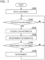
Fig. 3 is a flowchart illustrating a flow of processing of theCS 100. InFig. 3 , theassignment unit 50 performs initial assignment of assigning thedistributed antenna 30 to be connected to the signal processing unit 10 (step S101). This assignment may be assigned according to setting by the station operator, may be assigned by equal assignment, or may be assigned according to the processing capability of thesignal processing unit 10. - The
acquisition unit 40 determines whether an acquisition event has arrived (step S102). For example, in a case where the acquisition event is acquired at predetermined time intervals, the acquisition event may be an arrival of the time or an acquisition instruction from a host device or the like. - When the acquisition event arrives (step S102: YES), the
acquisition unit 40 acquires the above-described load information indicating the load of the signal processing unit 10 (step S103). The acquired load information is output to theassignment unit 50. - The
assignment unit 50 determines whether to reassign the distributedantenna 30 connected to thesignal processing unit 10 on the basis of the load information (step S104). Here, theassignment unit 50 may determine whether to perform the reassignment processing by comparing with a threshold set for each of the number of connected user terminals, the user throughput, the number of traffic buffers, or the calling failure rate. Theassignment unit 50 may determine whether to perform the reassignment processing on the basis of the magnitude of the load bias of thesignal processing unit 10. Theassignment unit 50 may detect a failure (a failure such as a part of the distributedantenna 30 or the CS 100) and determine whether to perform the reassignment processing on the basis of the detection result. - As a result of the reassignment determination by the
assignment unit 50, when it is not determined to perform the reassignment processing (step S105: NO), theassignment unit 50 does not perform reassignment processing and the process returns to step S102. On the other hand, when it is determined to perform the reassignment processing (step S105: YES), theassignment unit 50 performs the reassignment processing (step S106) and the process returns to step S102. In this reassignment, assignment is performed such that the loads of the plurality ofsignal processing units 10 are leveled. - Specifically, in the reassignment processing in step S106, reassignment is performed in units of distributed
antenna 30. For example, reassignment processing is performed in which the distributedantenna 30 having the largest load is assigned to thesignal processing unit 10 having the smallest load. Alternatively, reassignment processing is performed in which one of the distributedantennas 30 assigned to thesignal processing unit 10 having the largest load is randomly selected and the selected distributedantenna 30 is assigned to thesignal processing unit 10 having the smallest load. As a result, it is possible to follow the load variation. - In the flowcharts described above, leveling is performed according to the comparison result with the threshold. On the other hand, when a predetermined trigger other than the acquisition event arrives without comparison with the threshold, it may be determined whether to perform the reassignment processing, and leveling may be performed. Examples of the predetermined trigger include a time when the variation in the load of the
signal processing unit 10 becomes large (a time when the variance becomes a predetermined value or more). - The load of the distributed
antenna 30 varies depending on the day of the week and the time zone. Therefore, a statistic indicating the load of the distributedantenna 30 may be obtained in advance for each day of the week and each time zone, and the connection destination of the distributedantenna 30 may be assigned on the basis of the statistic in the reassignment processing in step S106. For example, when a statistic indicating that the number of UEs connected to the predetermined distributedantenna 30 increases around daytime on Sunday is obtained, the assignment may be performed such that the connection destination of the predetermined distributedantenna 30 is a differentsignal processing unit 10 in response to arrival of the daytime on Sunday. - In the embodiment described above, the
switch 20 is provided outside theCS 100, but may be provided inside theCS 100. In thewireless communication system 1 according to the embodiment, the analog RoF technology is used as a communication method between the distributedantenna 30 and thesignal processing unit 10, but a digital RoF technology may be used instead of the analog RoF technology. This is because the processing of leveling the loads of the plurality of signal processing units does not depend on the communication method between the distributedantenna 30 and thesignal processing unit 10. - In the
wireless communication system 1, theCS 100 is connected to the distributedantenna 30 via theswitch 20, but may have a configuration using a plurality of CSs and switches. Fig. 7 illustrates a configuration example of awireless communication system 1000 using a plurality of CSs and switches. Thewireless communication system 1000 includes a plurality of (M: M is an integer of 2 or more) CSs 100-1, 100-2, ..., and 100-M. - The CSs 100-1, 100-2, ..., 100-M are connected to the distributed
antenna 30 via theswitch 200. In thewireless communication system 1000, the CSs 100-1, 100-2, ..., 100-M and theswitch 200 are connected by one signal line, but this is an example, and may be connected by a plurality of signal lines. - In the
wireless communication system 1000, each of the CSs 100-1, 100-2, ..., and 100-M includes one or more signal processing units, but theswitch 200 may have functions corresponding to the acquisition unit and the assignment unit without including the acquisition unit and the assignment unit described inFig. 2 . Alternatively, an operation system (OPS) of a higher order than the CSs 100-1, 100-2, ..., 100-M may be provided, and functions corresponding to the acquisition unit, the assignment unit, and the setting unit may be implemented by the OPS. Alternatively, the functions corresponding to the acquisition unit and the assignment unit may be implemented by exchanging the load information and the assignment information between the CSs 100-1, 100-2, ..., 100-M. In thewireless communication system 1000, in a case where the CSs 100-1, 100-2, ..., 100-M have an acquisition unit and an assignment unit, it may be function as the acquisition unit and the assignment unit to be assigned to the signal processing units included in the CSs themselves. - As described above, when the present embodiment is applied even when spanning a plurality of CSs, not only the distribution of the load information but also the redundancy at the time of failure of the CS can be secured.
- The
acquisition unit 40 and theassignment unit 50 include a processor such as a central processing unit (CPU) and a memory. In this case, theacquisition unit 40 and theassignment unit 50 function as theacquisition unit 40 and theassignment unit 50 by the processor executing a program. All or some of the functions of theacquisition unit 40 and theassignment unit 50 may be realized by using hardware such as an application specific integrated circuit (ASIC), a programmable logic device (PLD), or a field programmable gate array (FPGA). The program may be recorded in a computer-readable recording medium. Examples of the computer-readable recording medium include a portable medium such as a flexible disk, a magneto-optical disk, a ROM, a CD-ROM, and a semiconductor storage device (for example, a solid state drive (SSD)), and a storage device such as a hard disk and a semiconductor storage device incorporated in a computer system. The program may be transmitted via a telecommunication line. - While the embodiments of this invention have been described in detail with reference to the drawings, specific configurations are not limited to these embodiments, and include designs and the like without departing from the spirit of this invention.
- The present invention is applicable to a wireless communication system having a relatively large load fluctuation such as a large change in the number of user terminals connected.
-
- 1
- Wireless communication system
- 10
- Signal processing unit
- 20
- Switch
- 30
- Distributed antenna
- 40
- Acquisition unit
- 50
- Assignment unit
- 100
- CS
Claims (5)
- A control method in a wireless communication system including a plurality of distributed antennas that perform wireless communication with a user terminal, and a plurality of signal processing units that are connected to the plurality of distributed antennas and perform signal processing,
the control method comprising:an initial assignment step of assigning a distributed antenna to be connected to a signal processing unit;an acquisition step of acquiring load information indicating a load of the signal processing unit;a determination step of determining whether to reassign the distributed antenna to be connected to the signal processing unit on the basis of the load information acquired in the acquisition step; anda reassignment step of performing reassignment and leveling loads of the plurality of signal processing units when it is determined to reassign in the determination step. - The control method according to claim 1, wherein, in the initial assignment step and the reassignment step, the signal processing unit as a connection destination of the distributed antenna is assigned by using a switch that switches the connection destination of the distributed antenna.
- The control method according to claim 1 or 2, wherein the load information indicates a number of connected user terminals that perform wireless communication with the distributed antenna, a user throughput in a user terminal that performs wireless communication with the distributed antenna, a number of traffic buffers in the signal processing unit, or a calling failure rate in the signal processing unit.
- The control method according to claim 1, wherein, in the reassignment step, the signal processing unit as the connection destination of the distributed antenna is assigned based on a statistic indicating a load of the distributed antenna.
- A wireless communication system comprising a plurality of distributed antennas that perform wireless communication with a user terminal, and a plurality of signal processing units that are connected to the plurality of distributed antennas and perform signal processing,
the wireless communication system comprising:an initial assignment unit that assigns a distributed antenna to be connected to a signal processing unit;an acquisition unit that acquires load information indicating loads of the signal processing unit;a determination unit that determines whether to reassign the distributed antenna to be connected to the signal processing unit on the basis of the load information acquired by the acquisition unit; anda reassignment unit that performs reassignment and levels loads of the plurality of signal processing units when it is determined to reassign by the determination unit.
Applications Claiming Priority (1)
| Application Number | Priority Date | Filing Date | Title |
|---|---|---|---|
| PCT/JP2021/018543 WO2022244035A1 (en) | 2021-05-17 | 2021-05-17 | Control method and wireless communication system |
Publications (2)
| Publication Number | Publication Date |
|---|---|
| EP4344075A1 true EP4344075A1 (en) | 2024-03-27 |
| EP4344075A4 EP4344075A4 (en) | 2025-03-19 |
Family
ID=84141287
Family Applications (1)
| Application Number | Title | Priority Date | Filing Date |
|---|---|---|---|
| EP21940656.8A Pending EP4344075A4 (en) | 2021-05-17 | 2021-05-17 | CONTROL METHOD AND WIRELESS COMMUNICATION SYSTEM |
Country Status (4)
| Country | Link |
|---|---|
| US (1) | US12587236B2 (en) |
| EP (1) | EP4344075A4 (en) |
| JP (1) | JP7678367B2 (en) |
| WO (1) | WO2022244035A1 (en) |
Family Cites Families (15)
| Publication number | Priority date | Publication date | Assignee | Title |
|---|---|---|---|---|
| EP1484935B1 (en) | 2002-03-13 | 2011-05-11 | Mitsubishi Electric Corporation | Radio area network control system and wide radio area network control system |
| US8155058B2 (en) | 2009-01-30 | 2012-04-10 | Aruba Networks, Inc. | Client balancing in wireless networks |
| JP5001983B2 (en) | 2009-07-21 | 2012-08-15 | 株式会社エヌ・ティ・ティ・ドコモ | Communication control system and communication control method |
| JP5379177B2 (en) * | 2011-02-10 | 2013-12-25 | 株式会社日立製作所 | Distributed antenna system, base station apparatus, and radio resource control method |
| BR112014010895B1 (en) * | 2011-11-07 | 2022-06-14 | Dali Systems Co., Ltd | SYSTEM AND METHOD FOR MANAGING RESOURCE USE IN A DISTRIBUTED ANTENNA SYSTEM |
| EP2818002A4 (en) | 2012-02-24 | 2015-10-28 | Intel Corp | Cooperative radio access network with centralized base station baseband unit (bbu) processing pool |
| WO2014034118A1 (en) * | 2012-08-29 | 2014-03-06 | 日本電気株式会社 | Communication system, base station, and communication method |
| EP2753142B1 (en) | 2013-01-08 | 2015-08-19 | Alcatel Lucent | Apparatus, method and computer program for splitting baseband data processing between a plurality of baseband processing units |
| JP2017157876A (en) * | 2014-07-07 | 2017-09-07 | 株式会社東芝 | Wireless communication system, control device, wireless communication method, control method and terminal |
| JP2016208227A (en) | 2015-04-21 | 2016-12-08 | 株式会社日立製作所 | Traffic control apparatus and method, distributed antenna system |
| EP3824678B1 (en) * | 2018-07-20 | 2026-03-25 | Telefonaktiebolaget LM Ericsson (publ) | Saving power in remote radio heads |
| US11483848B2 (en) | 2019-01-08 | 2022-10-25 | Commscope Technologies Llc | Distributed physical-layer processing by remote units of cloud/centralized radio access network (C-RAN) |
| WO2020197464A1 (en) * | 2019-03-26 | 2020-10-01 | Telefonaktiebolaget Lm Ericsson (Publ) | Interconnect in multiple-input multiple-output communication system |
| US11363678B2 (en) * | 2019-08-16 | 2022-06-14 | Commscope Technologies Llc | Self-optimization of mobile networks using a distributed antenna system |
| US12587863B2 (en) * | 2021-05-17 | 2026-03-24 | Ntt, Inc. | Control method and wireless communication system |
-
2021
- 2021-05-17 JP JP2023521985A patent/JP7678367B2/en active Active
- 2021-05-17 US US18/290,421 patent/US12587236B2/en active Active
- 2021-05-17 WO PCT/JP2021/018543 patent/WO2022244035A1/en not_active Ceased
- 2021-05-17 EP EP21940656.8A patent/EP4344075A4/en active Pending
Also Published As
| Publication number | Publication date |
|---|---|
| US20240250718A1 (en) | 2024-07-25 |
| EP4344075A4 (en) | 2025-03-19 |
| US12587236B2 (en) | 2026-03-24 |
| JP7678367B2 (en) | 2025-05-16 |
| WO2022244035A1 (en) | 2022-11-24 |
| JPWO2022244035A1 (en) | 2022-11-24 |
Similar Documents
| Publication | Publication Date | Title |
|---|---|---|
| US20100246529A1 (en) | Wireless communication terminal and wireless communication system | |
| CN102077683A (en) | Distributed antenna system in a communication network | |
| KR20110071102A (en) | Dynamic Sector Generation in Wireless Communication Systems | |
| KR20190050818A (en) | Antenna configuration method, terminal device, and antenna circuit | |
| WO2019174745A1 (en) | Determining beam settings for beam management | |
| US12335865B2 (en) | Base stations and methods for wireless communication networks | |
| JP2001119745A (en) | Channel identifier assignment method and mobile communication system | |
| EP4344279B1 (en) | Control method and wireless communication system | |
| US12587236B2 (en) | Control method and wireless communication system | |
| US20250365651A1 (en) | Client assisted off-channel scan | |
| US10623098B2 (en) | Access method, apparatus, device, and system for visible light communication | |
| KR101410994B1 (en) | Mobile communication system and digital signal processing apparatus, and method for setting area of joint transmission in the same | |
| US11405790B2 (en) | System and method to partition radio spectrum in a mixed client environment for efficient 802.11ax transmissions | |
| KR100427006B1 (en) | Base station condition testing system using a terminal in CDMA(code division multiple access) | |
| CN114244486B (en) | Method, device, equipment and storage medium for dynamically configuring signal resources | |
| JP6450260B2 (en) | Access point control device, access point control method, and access point control program | |
| JP2015008363A (en) | Distributed antenna system, management control device, management control device control method and control program | |
| KR101870767B1 (en) | Method and Apparatus for Transmitting Data Stream in MIMO System | |
| EP4061047B1 (en) | Mobile communications base station site survey | |
| KR102676911B1 (en) | Methods and apparatus for controlling handover and beamforming | |
| JP4510888B2 (en) | Resource distribution and signal routing method in a centralized base station | |
| EP3337216B1 (en) | Radio resource scheduling method, radio base station, and system | |
| US7123605B1 (en) | Method and system for re-assignment of packet pipes | |
| KR20150103833A (en) | Data processing apparatus and cell operation method for base station | |
| JP7340338B2 (en) | Base station, wireless communication system, and control method |
Legal Events
| Date | Code | Title | Description |
|---|---|---|---|
| STAA | Information on the status of an ep patent application or granted ep patent |
Free format text: STATUS: THE INTERNATIONAL PUBLICATION HAS BEEN MADE |
|
| PUAI | Public reference made under article 153(3) epc to a published international application that has entered the european phase |
Free format text: ORIGINAL CODE: 0009012 |
|
| STAA | Information on the status of an ep patent application or granted ep patent |
Free format text: STATUS: REQUEST FOR EXAMINATION WAS MADE |
|
| 17P | Request for examination filed |
Effective date: 20231116 |
|
| AK | Designated contracting states |
Kind code of ref document: A1 Designated state(s): AL AT BE BG CH CY CZ DE DK EE ES FI FR GB GR HR HU IE IS IT LI LT LU LV MC MK MT NL NO PL PT RO RS SE SI SK SM TR |
|
| DAV | Request for validation of the european patent (deleted) | ||
| DAX | Request for extension of the european patent (deleted) | ||
| REG | Reference to a national code |
Ref country code: DE Ref legal event code: R079 Free format text: PREVIOUS MAIN CLASS: H04B0007022000 Ipc: H04W0088080000 |
|
| A4 | Supplementary search report drawn up and despatched |
Effective date: 20250213 |
|
| RIC1 | Information provided on ipc code assigned before grant |
Ipc: H04W 88/08 20090101AFI20250207BHEP |
|
| RAP3 | Party data changed (applicant data changed or rights of an application transferred) |
Owner name: NTT, INC. |
|
| GRAP | Despatch of communication of intention to grant a patent |
Free format text: ORIGINAL CODE: EPIDOSNIGR1 |
|
| STAA | Information on the status of an ep patent application or granted ep patent |
Free format text: STATUS: GRANT OF PATENT IS INTENDED |
|
| INTG | Intention to grant announced |
Effective date: 20260107 |
|
| GRAS | Grant fee paid |
Free format text: ORIGINAL CODE: EPIDOSNIGR3 |
|
| GRAA | (expected) grant |
Free format text: ORIGINAL CODE: 0009210 |
|
| STAA | Information on the status of an ep patent application or granted ep patent |
Free format text: STATUS: THE PATENT HAS BEEN GRANTED |