EP4344049A1 - Electric machine system - Google Patents
Electric machine system Download PDFInfo
- Publication number
- EP4344049A1 EP4344049A1 EP22872677.4A EP22872677A EP4344049A1 EP 4344049 A1 EP4344049 A1 EP 4344049A1 EP 22872677 A EP22872677 A EP 22872677A EP 4344049 A1 EP4344049 A1 EP 4344049A1
- Authority
- EP
- European Patent Office
- Prior art keywords
- demagnetization
- electric machine
- rotor
- current
- magnetic flux
- Prior art date
- Legal status (The legal status is an assumption and is not a legal conclusion. Google has not performed a legal analysis and makes no representation as to the accuracy of the status listed.)
- Pending
Links
Images



Classifications
-
- H—ELECTRICITY
- H02—GENERATION; CONVERSION OR DISTRIBUTION OF ELECTRIC POWER
- H02P—CONTROL OR REGULATION OF ELECTRIC MOTORS, ELECTRIC GENERATORS OR DYNAMO-ELECTRIC CONVERTERS; CONTROLLING TRANSFORMERS, REACTORS OR CHOKE COILS
- H02P29/00—Arrangements for regulating or controlling electric motors, appropriate for both AC and DC motors
- H02P29/02—Providing protection against overload without automatic interruption of supply
- H02P29/032—Preventing damage to the motor, e.g. setting individual current limits for different drive conditions
-
- H—ELECTRICITY
- H02—GENERATION; CONVERSION OR DISTRIBUTION OF ELECTRIC POWER
- H02P—CONTROL OR REGULATION OF ELECTRIC MOTORS, ELECTRIC GENERATORS OR DYNAMO-ELECTRIC CONVERTERS; CONTROLLING TRANSFORMERS, REACTORS OR CHOKE COILS
- H02P21/00—Arrangements or methods for the control of electric machines by vector control, e.g. by control of field orientation
- H02P21/22—Current control, e.g. using a current control loop
-
- H—ELECTRICITY
- H02—GENERATION; CONVERSION OR DISTRIBUTION OF ELECTRIC POWER
- H02K—DYNAMO-ELECTRIC MACHINES
- H02K11/00—Structural association of dynamo-electric machines with electric components or with devices for shielding, monitoring or protection
- H02K11/20—Structural association of dynamo-electric machines with electric components or with devices for shielding, monitoring or protection for measuring, monitoring, testing, protecting or switching
- H02K11/25—Devices for sensing temperature, or actuated thereby
-
- H—ELECTRICITY
- H02—GENERATION; CONVERSION OR DISTRIBUTION OF ELECTRIC POWER
- H02K—DYNAMO-ELECTRIC MACHINES
- H02K11/00—Structural association of dynamo-electric machines with electric components or with devices for shielding, monitoring or protection
- H02K11/20—Structural association of dynamo-electric machines with electric components or with devices for shielding, monitoring or protection for measuring, monitoring, testing, protecting or switching
- H02K11/27—Devices for sensing current, or actuated thereby
-
- H—ELECTRICITY
- H02—GENERATION; CONVERSION OR DISTRIBUTION OF ELECTRIC POWER
- H02P—CONTROL OR REGULATION OF ELECTRIC MOTORS, ELECTRIC GENERATORS OR DYNAMO-ELECTRIC CONVERTERS; CONTROLLING TRANSFORMERS, REACTORS OR CHOKE COILS
- H02P21/00—Arrangements or methods for the control of electric machines by vector control, e.g. by control of field orientation
- H02P21/06—Rotor flux based control involving the use of rotor position or rotor speed sensors
- H02P21/10—Direct field-oriented control; Rotor flux feed-back control
Definitions
- the present disclosure relates to an electric machine system.
- the present application is based on Japanese Patent Application No. 2021-153869 filed on September 22, 2021 .
- the present application claims the benefit of priority to Japanese Patent Application No. 2021-153869 .
- the entire contents of Japanese Patent Application No. 2021-153869 are incorporated herein by reference.
- Patent Literature 1, 2, and 3 disclose techniques related to electric machines such as an electric motor and a generator including a coil and a magnet.
- Patent Literature 1 discloses an efficient slip-free synchronous motor.
- Patent Literature 2 discloses a technique that suppresses an increase in magnetization current at the time of demagnetization and at the time of magnetization, and enables variable speed operation in a wide range from low speed to high speed with high output.
- Patent Literature 3 discloses an energy efficient magnetic flux variable rotating electric machine system.
- a voltage is generated in the coil.
- the induced voltage induced in the coil for example, even when an abnormality such as a short circuit failure occurs in a circuit such as the coil, the induced voltage continues to be generated as the rotating operation continues.
- the fault current flowing when such an abnormality occurs causes an unintended failure. Therefore, the electric machine is required to cope with a fault current.
- the present disclosure describes an electric machine system which may reduce the magnitude of a fault current.
- An electric machine system of the present disclosure includes an electric machine including a rotor that includes a magnet and rotates together with a shaft, and a coil fixedly disposed to surround the rotor; a power converter that outputs an output current to the coil of the electric machine; and a controller that controls the power converter.
- the controller includes a signal output unit that outputs a signal for controlling a mode of the output current to the power converter, and an abnormality detection unit that receives an abnormality signal indicating an abnormal situation.
- the signal output unit outputs a demagnetization control signal to the power converter when the abnormality detection unit receives the abnormality signal.
- the power converter causes a demagnetization current for a demagnetization magnetic flux for demagnetizing the magnet of the rotor to flow through the coil in response to an input of the demagnetization control signal.
- the electric machine system of the present disclosure may reduce the magnitude of the fault current.
- An electric machine system of the present disclosure includes an electric machine including a rotor that includes a magnet and rotates together with a shaft, and a coil fixedly disposed to surround the rotor; a power converter that outputs an output current to the coil of the electric machine; and a controller that controls the power converter.
- the controller includes a signal output unit that outputs a signal for controlling a mode of the output current to the power converter, and an abnormality detection unit that receives an abnormality signal indicating an abnormal situation.
- the signal output unit outputs a demagnetization control signal to the power converter when the abnormality detection unit receives the abnormality signal.
- the power converter causes a demagnetization current for a demagnetization magnetic flux for demagnetizing the magnet of the rotor to flow through the coil in response to an input of the demagnetization control signal.
- the controller that has detected the abnormal situation generates a demagnetization magnetic flux for demagnetizing the magnet of the rotor by the coil of the stator by controlling the power converter.
- the magnitude of the fault current generated in the coil of the stator may be reduced.
- the electric machine system of the present disclosure may reduce the magnitude of the fault current by controlling the power converter originally provided.
- the power converter may cause the demagnetization current for the demagnetization magnetic flux including a first demagnetization magnetic flux component in a direction opposite to a direction of a magnetic field generated by the magnet and synchronized with rotation of the magnet to flow through the coil in response to the input of the demagnetization control signal.
- the first demagnetization magnetic flux component generated by the coil acts as an external magnetic flux on the magnet of the rotor.
- the magnet of the rotor may be demagnetized by the external magnetic flux.
- the power converter may perform control such that a current flowing through a coil at a position where a d-axis component is larger than a q-axis component with respect to the rotor among coils surrounding the rotor becomes larger than a current flowing through a coil at a position where the q-axis component is larger than the d-axis component in response to the input of the demagnetization control signal.
- This operation may also reduce the magnitude of the fault current.
- the power converter may cause a current not to flow through a coil at a position where a q-axis component is larger than a d-axis component.
- the intensity of the demagnetization magnetic flux including the first demagnetization magnetic flux component may be the intensity that causes irreversible demagnetization of the magnet of the rotor. This configuration may also reduce the magnitude of the fault current.
- the demagnetization control signal may cause the power converter to output, to the coil, the demagnetization current for the demagnetization magnetic flux including a second demagnetization component of an alternating current interlinked with the magnet of the rotor.
- the controller may include a demagnetization evaluation unit that evaluates a degree of irreversible demagnetization of the magnet of the rotor.
- the demagnetization evaluation unit may stop output of the demagnetization control signal from the signal output unit in a case where a degree of irreversible demagnetization of the magnet of the rotor is equal to or less than a threshold value. According to this configuration, the magnitude of the fault current may be reduced without continuing to provide a demagnetization current.
- the shaft may be connected to a rotating mechanism of a prime mover at a position different from a position where the rotor is provided.
- the shaft may receive power transmitted from the rotating mechanism to rotate the rotor.
- the electric machine may generate electric power due to rotation of the rotor.
- the electric machine system of the present disclosure may reduce the magnitude of the fault current that may be generated in the electric machine that generates electric power by controlling the power converter originally provided.
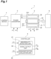
- the electric machine system 1 includes an electric machine 2, a power converter 3, and a controller 4.
- the electric machine 2 includes a coil and a magnet.
- the electric machine 2 is a generator.
- the electric machine 2 receives kinetic energy from an external device 6 and generates electric energy.
- the electric machine 2 may be an electric motor.
- the electric motor receives electric energy from the outside and generates kinetic energy.
- the electric machine 2 will be described as a generator.
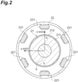
- the electric machine 2 includes a rotor 21 and a stator 22 as main components.
- the rotor 21 is a cylindrical member.
- the rotor 21 is fixed to a shaft 5. Both ends of the shaft 5 are supported by bearings 23.
- the rotor 21 rotates integrally with the shaft 5.
- the rotor 21 includes a permanent magnet 211 and an armour ring 212.
- the armour ring 212 may be provided as necessary. Therefore, the armour ring 212 may be omitted from the rotor 21.
- the cylindrical permanent magnet 211 is fixed to the shaft 5.
- the permanent magnet 211 may be, for example, a surface permanent magnet. As a result, two axes along the radial direction may be defined in the permanent magnet 211.
- a line connecting an N-pole and an S-pole of the permanent magnet 211 is defined as a d-axis.
- a q-axis is defined as an axis orthogonal to a d-axis.
- the permanent magnet 211 may be covered by a cylindrical armour ring 212.
- the stator 22 is disposed around the rotor 21.
- the stator 22 is fixed to a housing or the like of the electric machine 2.
- the stator 22 does not move with respect to the housing or the like of the electric machine 2.
- the stator 22 includes a plurality of coils 221 formed by winding conductive wires around teeth.
- the power converter 3 may also convert AC power into DC power.
- the power converter 3 may also convert DC power into AC power.
- the power converter 3 receives electric power from the electric machine 2.
- the power converter 3 converts a mode of the received power.
- the power converter 3 outputs the converted power to a loading device 7.
- the power converter 3 may also perform phase control related to the phase of the three-phase alternating current.
- the power converter 3 may advance the phase of the three-phase alternating current.
- the power converter 3 may also delay the phase of the three-phase alternating current.
- the input end of the shaft 5 is connected to the external device 6 (prime mover) as a driving source.
- the input end may be switchable between connection and disconnection with respect to the rotating mechanism which is the output end of the external device 6.
- the input end may be connected to the output end of the external device 6 not to be disconnected.
- the controller 4 controls the operation of the power converter 3.
- the controller 4 outputs a control signal to the power converter 3.
- the controller 4 is connected to the power converter 3 in a wired or wireless manner.
- the controller 4 is also connected to a device different from the power converter 3 in order to obtain information for outputting a control signal.
- the controller 4 may be connected to the electric machine 2.
- the electric machine 2 may be provided with several sensors.
- the controller 4 may obtain sensor signals output from these sensors.
- the controller 4 receives an abnormality signal ⁇ 1 and a current signal ⁇ 2 as input signals.
- the controller 4 outputs an operation control signal ⁇ 1 and a demagnetization control signal ⁇ 2 as output signals.
- the controller 4 is realized by a computer.
- the controller 4 includes one or more computers.
- a computer includes an arithmetic unit (processor), a main storage unit, an auxiliary storage unit, a communication control unit, an input device, and an output device.
- the controller 4 is configured by one or a plurality of computers configured by the hardware and software such as a program. In a case where the controller 4 includes a plurality of computers, these computers may be locally connected.
- the plurality of computers constituting the controller 4 may be connected via a communication network such as the Internet or an intranet. By this connection, one controller 4 is logically constructed.
- the controller 4 has several functional components realized by executing a program on the above hardware.
- the controller 4 includes an abnormality detection unit 41, a signal output unit 42, and a demagnetization evaluation unit 43 as functional components.
- the abnormality detection unit 41 receives the abnormality signal ⁇ 1.
- the abnormality signal ⁇ 1 indicates that the electric machine 2 is not in a normal operation state. Specifically, the abnormality signal ⁇ 1 indicates that an abnormality such as a short circuit occurs in the coil 221 of the electric machine 2.
- the abnormality signal ⁇ 1 may be input from, for example, a current sensor that senses a current generated by an abnormality.
- the abnormality signal ⁇ 1 may be input from, for example, a sensor that detects heat or light generated by a short circuit.
- the abnormality signal ⁇ 1 may be input from, for example, a magnetic sensor. That is, the abnormality signal ⁇ 1 may be input from various sensors.
- the abnormality signal ⁇ 1 may be output by a processing device that has received output signals from these sensors.
- the processing device receives an output signal from the sensor.
- the processing device executes predetermined signal processes on the received signal. As a result, the processing device generates a processed signal.
- the processing device may output the processed signal as the abnormality signal ⁇ 1.
- the abnormality signal ⁇ 1 may be a signal that is determined by human visual observation that an abnormality has occurred and is input to the abnormality detection unit 41 by a human through an input device.
- the controller 4 including the abnormality detection unit 41 switches the operation of the electric machine 2 to the operation when the abnormality occurs due to the input of the abnormality signal ⁇ 1.
- the situation in which the abnormality signal ⁇ 1 is input to the controller 4 is not limited to the short circuit.
- the abnormality signal ⁇ 1 may be input to the controller 4 due to a decrease in the supply amount of the refrigerant for cooling the electric machine 2.
- the abnormality signal ⁇ 1 may be input to the controller 4 due to supply abnormality such as clogging of the refrigerant. As a result, demagnetization of the permanent magnet 211 described later may be performed.
- the electric machine 2 of the present disclosure may be, for example, a generator mounted on an aircraft.
- the external device 6 such as an internal combustion engine (prime mover) is mounted on the aircraft in addition to the electric machine 2.
- the external device 6 includes a rotating body such as a turbine.
- the shaft 5 of the electric machine 2 is directly connected to the rotating body of the external device 6. Therefore, the rotor 21 rotates with the rotation of the rotating body of the external device 6. As a result, a current is generated in the coil 221. Even when an abnormality such as a short circuit occurs in the coil 221, it is difficult for the external device 6 such as an internal combustion engine to stop immediately. Therefore, even when an abnormality occurs, the rotational power continues to be transmitted from the external device 6 to the rotor 21 via the shaft 5.
- the signal output unit 42 outputs either the operation control signal ⁇ 1 or the demagnetization control signal ⁇ 2 to the power converter 3.
- the signal output unit 42 outputs the demagnetization control signal ⁇ 2 in response to the abnormality detection unit 41 receiving the abnormality signal. Conversely, the signal output unit 42 outputs the operation control signal ⁇ 1 when the abnormality detection unit 41 does not receive the abnormality signal.
- the operation control signal ⁇ 1 is for operating the electric machine 2 as a generator. As long as the electric machine 2 is brought into a desired operation state, the operation of the power converter 3 realized by the operation control signal ⁇ 1 is not limited at all.
- the power converter 3 that has received the operation control signal ⁇ 1 may output a current including a d-axis component and a q-axis component.
- the power converter 3 that has received the operation control signal ⁇ 1 may output a current including a q-axis component.
- the current including a q-axis component ideally means that the current output from the power converter 3 includes only a q-axis component and does not include a d-axis component.
- the current output from the power converter 3 may include a q-axis component as a main component, and may slightly include a d-axis component.
- the demagnetization control signal ⁇ 2 is for causing the permanent magnet 211 of the rotor 21 to be demagnetized.
- the abnormality signal ⁇ 1 has been described as indicating that an abnormality such as a short circuit has occurred.
- an abnormality such as a short circuit has occurred.
- the current fault current
- the electric machine 2 is cooled by oil, there is a concern that the oil ignites from a short circuit current.
- wear occurs in the peripheral device due to heat generation accompanying the short circuit.
- the peripheral device is worn due to heat generation caused by a fault current flowing through the coil 221. Therefore, it is necessary to take measures to cope with the fault current.
- the magnitude of the induced voltage and the magnitude of the fault current generated in the coil 221 are suppressed. Further, when the permanent magnet 211 is demagnetized completely, there is no magnetic flux interlinked with the coil 221. As a result, no induced voltage is generated in the coil 221, and no fault current is generated.
- the demagnetization of the permanent magnet 211 may be generated by several factors. In the first embodiment, an example of using demagnetization by an external magnetic flux will be described. In the second embodiment, an example of using demagnetization by heat will be described.
- the power converter 3 that has received the demagnetization control signal ⁇ 2 outputs a demagnetization current to the stator 22.
- the stator 22 that has received the demagnetization current generates a demagnetization magnetic flux D3 (refer to FIG. 3 ).
- the demagnetization magnetic flux D3 includes a first demagnetization magnetic flux component in a direction opposite to the direction of a magnet magnetic flux D2 generated by the permanent magnet 211.
- the demagnetization current that causes the demagnetization magnetic flux D3 may also be referred to as a d-axis current. In other words, the first demagnetization magnetic flux component is along the d-axis.
- the demagnetization current that generates the demagnetization magnetic flux D3 may include a d-axis current as a main component. That is, the demagnetization current that generates the demagnetization magnetic flux D3 may additionally include a q-axis current.
- the demagnetization magnetic flux D3 is synchronized with the rotation of the permanent magnet 211. That is, the demagnetization magnetic flux D3 including the first demagnetization magnetic flux component is a rotating magnetic field. As a result, as shown in FIGS. 3A, 3B, and 3C , the direction of the demagnetization magnetic flux D3 synchronized with the rotation of the rotor 21 is always opposite to the direction of the magnet magnetic flux D2 of the permanent magnet 211.
- the permanent magnet 211 seems to always receive the magnetic flux in the direction opposite to the direction of the magnet magnetic flux D2 generated by itself.
- the magnitude of the demagnetization magnetic flux D3 is constant. That is, the first demagnetization magnetic flux component included in the demagnetization magnetic flux D3 is synchronized with the rotation of the rotor 21. On the other hand, basically, the magnitude of the first demagnetization magnetic flux component does not need to change with the lapse of time.
- the magnitude of the first demagnetization magnetic flux component basically may or may not change with the lapse of time.
- the demagnetization magnetic flux D3 may include the first demagnetization magnetic flux component. Therefore, the demagnetization magnetic flux D3 may include a magnetic flux component not along the d-axis.
- the direction of the demagnetization magnetic flux D3 in which the first demagnetization magnetic flux component and the magnetic flux component not along the d-axis are combined does not completely match the direction of the d-axis.
- the permanent magnet 211 that has received the external magnetic flux generates reversible demagnetization and irreversible demagnetization according to the strength of the external magnetic flux.
- the demagnetization by the demagnetization magnetic flux D3 may be reversible demagnetization.
- the demagnetization by the demagnetization magnetic flux D3 may be irreversible demagnetization.
- the magnitude of the fault current may be reduced when the demagnetization magnetic flux D3 is applied.
- irreversible demagnetization when the degree of demagnetization is large, the occurrence of a fault current may be suppressed even when the application of the demagnetization magnetic flux D3 is stopped.
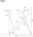
- demagnetization magnetic flux D3 causes reversible demagnetization or the demagnetization magnetic flux D3 causes irreversible demagnetization may be understood by referring to the magnetization curve shown in FIG. 4 .
- the magnetization curve of the permanent magnet 211 of the rotor 21 is known, reversible demagnetization and irreversible demagnetization may be randomly selected and generated.
- the horizontal axis in FIG. 4 indicates the strength of the magnetic field (H: unit A/m).
- the vertical axis represents the magnetic flux density (B: unit T).
- the graph G51 is a B-H curve (magnetic hysteresis curve) indicating the characteristics of the permanent magnet 211.
- the B-H curve indicates the magnetic flux density obtained by summing the external magnetic flux and the magnetic flux of the permanent magnet 211.
- the graph G52 is a J-H curve indicating the characteristics of the permanent magnet 211.
- the J-H curve indicates how much the magnitude of the magnetic flux of the permanent magnet 211 is changed by the external magnetic flux.
- the state of the permanent magnet 211 is the operating point P51 on the B-H curve (graph G51).
- the operating point P51 is the operating point P52 on the J-H curve (graph G52).
- a straight line G53 connecting the operating point P52 and the original point is determined.
- a demagnetization magnetic flux D3 as an external magnetic flux of which intensity is Hs is applied to the permanent magnet 211.
- the operating point P52 on the J-H curve (graph G52) changes to the operating point P53.
- the operating point P53 on the J-H curve (graph G52) is the operating point P54 on the B-H curve.
- the magnetic field of the permanent magnet 211 tries to return to the original state following the straight line G55.
- the straight line G55 has a slope corresponding to the B-H curve (graph G51). Then, the state of the permanent magnet 211 may not return to the original operating point P51.
- the state of the permanent magnet 211 returns to the intersection point (operating point P55) of the straight line G55 connecting the original operating point P51 and the original point.
- the magnetic flux density of the operating point P55 is smaller than the magnetic flux density of the original operating point P51. That is, irreversible demagnetization occurs in the permanent magnet 211.
- the demagnetization evaluation unit 43 may evaluate the state of demagnetization of the permanent magnet 211 of the rotor 21 using, for example, the magnitude of a fault current generated in the coil 221.
- the demagnetization state indicates, for example, a state of the permanent magnet 211 in which a fault current smaller than an allowable current value occurs. For example, during the period in which the demagnetization control signal ⁇ 2 is output, the permanent magnet 211 is sufficiently demagnetized. Next, the output of the demagnetization control signal ⁇ 2 is stopped for a predetermined period. Then, demagnetization of the permanent magnet 211 due to the application of the demagnetization magnetic flux D3 does not occur.
- the magnitude of the magnetic flux generated by the permanent magnet 211 is reduced by irreversible demagnetization.
- a fault current corresponding to the magnitude of the magnetic flux density reduced by the irreversible demagnetization is generated.
- the demagnetization evaluation unit 43 stops the application of the demagnetization magnetic flux D3 for a predetermined period after applying the demagnetization magnetic flux D3.
- the demagnetization evaluation unit 43 obtains the magnitude of the fault current generated in a state where the application of the demagnetization magnetic flux D3 is stopped. Then, the demagnetization evaluation unit 43 selects continuation or stop of the application of the demagnetization magnetic flux D3 according to the magnitude of the fault current.
- the demagnetization evaluation unit 43 may stop the application of the demagnetization magnetic flux D3 on condition that the sensor does not detect an abnormal state and does not output an abnormality signal.
- the demagnetization evaluation unit 43 may determine whether to stop the application of the demagnetization magnetic flux D3 by using the result of measuring the magnetic flux of the interlinked rotors.
- the demagnetization evaluation unit 43 may select continuation or stop of the application of the demagnetization magnetic flux D3 by comparing the measurement value with a threshold value. In this case, an operation of stopping the demagnetization current for a predetermined period is unnecessary.
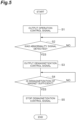
- the signal output unit 42 outputs the operation control signal ⁇ 1 (S1).
- the abnormality detection unit 41 determines whether the abnormality signal ⁇ 1 is input (S2). In a case where there is no input of the abnormality signal ⁇ 1 (S2: NO), the presence or absence of the input of the abnormality signal ⁇ 1 is determined again after a predetermined standby period. That is, the operation of determining the presence or absence of the input of the abnormality signal ⁇ 1 and the standby operation are repeated until the input of the abnormality signal ⁇ 1 occurs.
- the signal output unit 42 stops the output of the operation control signal ⁇ 1 and starts the output of the demagnetization control signal ⁇ 2 (S3).
- the intensity of the demagnetization magnetic flux D3 determined by the demagnetization control signal ⁇ 2 may be determined by a demagnetization mode (reversible demagnetization, irreversible demagnetization, or complete demagnetization).
- the demagnetization magnetic flux D3 is synchronized with the rotation of the rotor 21. It is difficult to directly detect the rotation of the rotor 21 in the abnormal state. Therefore, the signal output unit 42 may perform feedback control of the phase of the demagnetization magnetic flux D3 to reduce the magnitude of the fault current.
- the power converter 3 that has received the input of the demagnetization control signal ⁇ 2 may perform control such that a current flowing through a coil at a position where a d-axis component is larger than a q-axis component with respect to the rotor 21 among coils 221 surrounding the rotor 21 becomes larger than a current flowing through the coil at a position where the q-axis component is larger than the d-axis component.
- the power converter 3 may not cause a current to flow through the coil at a position where the q-axis component is larger than the d-axis component.
- the power converter 3 that has received the input of the demagnetization control signal ⁇ 2 controls the current flowing through the coil such that the d-axis component is larger than the q-axis component among the coils 221 surrounding the rotor 21.
- the current flowing through the coil at the position where the d-axis component is larger than the q-axis component with respect to the rotor 21 is larger than the current flowing through the coil at the position where the q-axis component is larger than the d-axis component.
- the current may not flow through the coil at a position where the q-axis component is larger than the d-axis component.
- the demagnetization evaluation unit 43 evaluates the degree of demagnetization of the permanent magnet 211 (S4).
- a specific method of the evaluation is, for example, as described above.
- the demagnetization evaluation unit 43 continues to output the demagnetization control signal ⁇ 2.
- the demagnetization evaluation unit 43 stop outputting the demagnetization control signal ⁇ 2.
- the electric machine system 1 includes the electric machine 2 including the rotor 21 that includes the permanent magnet 211 and rotates together with the shaft 5 and the coil 221 fixedly disposed to surround the rotor 21; the power converter 3 that outputs an output current to the coil 221 of the electric machine 2; and the controller 4 that controls the power converter 3.
- the controller 4 includes the signal output unit 42 that outputs a signal for controlling a mode of the output current to the power converter 3; and the abnormality detection unit 41 that receives an abnormality signal ⁇ 1 indicating an abnormal situation in a case of the abnormal situation in which the generation of the fault current generated in the coil 221 by the rotation of the rotor 21 should be suppressed.
- the signal output unit 42 When the abnormality detection unit 41 receives the abnormality signal ⁇ 1, the signal output unit 42 outputs the demagnetization control signal ⁇ 2 to the power converter 3.
- the demagnetization control signal ⁇ 2 causes the power converter 3 to output, to the coil 221, a demagnetization current for a demagnetization magnetic flux D3 that demagnetizes the permanent magnet 211 of the rotor 21.
- the controller 4 that has detected the abnormal situation gives the demagnetization magnetic flux D3 for demagnetizing the permanent magnet 211 of the rotor 21 to the coil 221 of the stator 22 by controlling the power converter 3.
- the permanent magnet 211 of the rotor 21 is demagnetized, the magnitude of the fault current generated in the coil 221 of the stator 22 may be suppressed.
- the electric machine system 1 may reduce the magnitude of the fault current by controlling the power converter 3 originally provided.
- the electric machine system 1 of the present disclosure does not include a circuit breaker provided in an electrical output path of the electric machine 2.
- the electric machine system 1 is not equipped with other devices for taking measures against a fault current, such as a clutch that physically interrupts the rotation of the shaft 5. Therefore, the electric machine system 1 may reduce the weight of the electric machine system 1 as compared with a system equipped with such an interrupting device.
- the controller 4 that controls the power generation or the operation of the electric machine 2 in the normal state takes a measure against occurrence of an abnormality.
- the electric machine system 1 applies a reverse magnetic field to the permanent magnet 211 of the rotor 21 by utilizing a current control function of an inverter or a converter that drives the electric machine 2 when a failure of the generator that is the electric machine 2 is detected.
- a power generation function that generates a fault current may be reduced or eliminated. Therefore, a large fault current may be suppressed from continuing to flow.
- the electric machine system 1 includes a fault protection system regardless of the presence or absence of additional components such as a circuit breaker and a clutch. Furthermore, a safety device provided separately from the electric machine 2 such as a circuit breaker may not cope with an internal short circuit failure inside the electric machine 2. However, the electric machine system 1 may also cope with an internal short circuit failure inside the electric machine 2. When additional components are not provided, an increase in the number of parts constituting the electric machine system 1 is also suppressed. As a result, the maintainability of the electric machine system 1 may also be improved.
- the direction of the demagnetization magnetic flux D3 generated by the demagnetization control signal ⁇ 2 is opposite to the direction of the magnet magnetic flux D2 generated by the permanent magnet 211.
- the power converter 3 outputs a demagnetization current for the demagnetization magnetic flux D3 including the first demagnetization magnetic flux component synchronized with the rotation of the permanent magnet 211 to the coil 221.
- the first demagnetization magnetic flux component generated by the coil 221 acts as an external magnetic flux on the permanent magnet 211 of the rotor 21.
- the magnet of the rotor 21 may be demagnetized by the external magnetic flux.
- the intensity of the demagnetization magnetic flux D3 including the first demagnetization magnetic flux component is an intensity that causes irreversible demagnetization of the permanent magnet 211 of the rotor 21. This configuration may also reduce the magnitude of the fault current.
- the controller 4 includes the demagnetization evaluation unit 43 that evaluates the degree of irreversible demagnetization of the permanent magnet 211 of the rotor 21.
- the demagnetization evaluation unit 43 stops the output of the demagnetization control signal ⁇ 2 from the signal output unit 42. According to this configuration, the fault current may be suppressed without continuing to provide the demagnetization current.
- the electric machine system 1 according to the second embodiment will be described.
- the electric machine system 1 of the second embodiment is different from that of the first embodiment in the principle adopted for demagnetization. Therefore, since physical components of the electric machine system 1 are the same as those in the first embodiment, detailed description thereof will be omitted.
- the electric machine system 1 of the second embodiment is different from that of the first embodiment in the operation of the power converter 3 according to the demagnetization control signal ⁇ 2 generated by the signal output unit 42 of the controller 4 and the operation of the stator 22.
- the controller 4 of the first embodiment demagnetizes the permanent magnet 211 of the rotor 21 by the external magnetic flux.
- the controller 4 of the second embodiment demagnetizes the permanent magnet 211 of the rotor 21 by heat. That is, the demagnetization control signal ⁇ 2 output from the controller 4 of the second embodiment generates a magnetic field that heats the permanent magnet 211 of the rotor 21.
- FIG. 6A illustrates a demagnetization current output to the stator 22 by the power converter 3 that has received the demagnetization control signal ⁇ 2.
- the demagnetization current is an alternating current.
- the demagnetization current shown in FIG. 6A includes an AC component of which the magnitude changes to a plus side and a minus side across zero.
- the demagnetization current does not include a DC component (bias component) that does not change with the lapse of time.
- demagnetization magnetic flux D3 is also an alternating magnetic field in which the magnitude of the magnetic field changes with the lapse of time.
- the demagnetization current may include an AC component.
- the demagnetization current may include a DC component in addition to an AC component.
- the switching frequency may be lowered.
- an effect of increasing the eddy current based on the high-frequency ripple current (refer to the enlarged portion of FIG. 6B ) may also be obtained.
- the technique for lowering the switching frequency is not limited to the example shown in FIG. 6B .
- the technique for lowering the switching frequency is also applicable to the example of FIG. 6A .
- the technique for lowering the switching frequency may also be applied to exemplary operations shown in FIGS. 6C, 6D, 6E, and 6F described later. According to the technique for lowering the switching frequency, since a high-frequency component is included, the heating effect may be enhanced.
- FIG. 8A also illustrates the demagnetization current output to the stator 22 by the power converter 3 that has received the demagnetization control signal ⁇ 2.
- the demagnetization current is an alternating current.
- the demagnetization current shown in FIG. 8A includes an AC component of which the magnitude changes to a plus side and a minus side across zero.
- the demagnetization current shown in FIG. 8A does not include a DC component (bias component) that does not change with the lapse of time.
- demagnetization magnetic flux D3 is also an alternating magnetic field in which the magnitude of the magnetic field changes with the lapse of time.
- the demagnetization current may include an AC component.
- the demagnetization current may include a DC component in addition to an AC component.
- the sign of the combined current of the AC component and the DC component does not vary with time. That is, the sign of the combined current may be always positive or always negative.
- the switching frequency may be lowered.
- an effect of increasing the eddy current based on the high-frequency ripple current may also be obtained.
- the high-frequency ripple current is shown in an enlarged portion of FIGS. 8A and 8B as an example.
- the technique for lowering the switching frequency is not limited to the example illustrated in FIGS. 8A and 8B .
- the technique for lowering the switching frequency may also be applied to exemplary operations shown in FIGS. 8C, 8D, 8E, and 8F described later.
- the technique for lowering the switching frequency since a high-frequency component is included, the heating effect may be enhanced.
- reversible demagnetization and irreversible demagnetization may be intentionally selected when the magnetization characteristics of the permanent magnet 211 as shown in FIG. 4 are known.
- the reversible demagnetization and the irreversible demagnetization may be intentionally selected when the magnetization characteristics of the permanent magnet 211 are known.
- FIG. 7 illustrates a B-H curve indicating the magnetization characteristics of the permanent magnet 211.
- a B-H curve shown in the graph G71 indicates the magnetization characteristics of the permanent magnet 211 when the temperature of the permanent magnet 211 is room temperature.
- a B-H curve shown in the graph G72 indicates the magnetization characteristics of the permanent magnet 211 when the temperature of the permanent magnet 211 is high. As shown in the graphs G71 and G72, the magnetization characteristics of the permanent magnet 211 changes depending on the temperature.
- the temperature of the permanent magnet 211 is room temperature and in a state of the operating point P71.
- the magnetization characteristics of the permanent magnet 211 has changed to the characteristics shown in the graph G72.
- the operating point P72 is determined by the temperature coefficient of the residual magnetic flux density (Br) of the permanent magnet 211.
- the straight line G73 may be defined by the temperature coefficient of the residual magnetic flux density (Br).
- the permanent magnet 211 operates in the state shown on the straight line G73 according to the temperature. That is, the operating point P72 of the heated permanent magnet 211 is an intersection of the B-H curve which is the graph G72 and the straight line G73.
- the degree of heating of the permanent magnet 211 may be controlled by, for example, the amplitude and frequency of the AC component.
- the degree of heating of the permanent magnet 211 may also be adjusted by controlling the switching speed and changing the magnitude of ripples.
- the demagnetization control signal ⁇ 2 causes the power converter 3 to output, to the coil 221, a demagnetization current for a demagnetization magnetic flux including the second demagnetization component of an alternating current interlinked with the permanent magnet 211 of the rotor 21.
- a demagnetization current for a demagnetization magnetic flux including the second demagnetization component of an alternating current interlinked with the permanent magnet 211 of the rotor 21.
- the electric machine system of the present disclosure has been described above in detail based on the embodiment. However, the electric machine system of the present disclosure is not limited to the above contents. The electric machine system of the present disclosure may be variously modified without departing from the gist thereof.
- the demagnetization current has been described as a d-axis current.
- the demagnetization current may be a q-axis current as shown in FIG. 6C .
- the demagnetization current, which is a q-axis current may include only an AC component as shown in FIG. 6C .
- the demagnetization current, which is a q-axis current may include an AC component and a DC component as shown in FIG. 6D .
- the demagnetization current may be a combined current of a d-axis current component and a q-axis current component.
- the demagnetization current which is a dq-axis combined current may include only an AC component as shown in FIG. 6E .
- the demagnetization current, which is the dq-axis combined current may include an AC component and a DC component as shown in FIG. 6F .
- the present disclosure includes the following configurations.
- the electric machine system of the present disclosure is [1] "an electric machine system including: an electric machine including a rotor that includes a magnet and rotates together with a shaft, and a coil fixedly disposed to surround the rotor; a power converter configured to output an output current to the coil of the electric machine; and a controller that controls the power converter, in which the controller includes a signal output unit configured to output a signal for controlling a mode of the output current to the power converter, and an abnormality detection unit configured to receive an abnormality signal indicating an abnormal situation, the signal output unit outputs a demagnetization control signal to the power converter when the abnormality detection unit receives the abnormality signal, and the power converter causes a demagnetization current for a demagnetization magnetic flux for demagnetizing the magnet of the rotor to flow through the coil in response to an input of the demagnetization control signal".
- the electric machine system of the present disclosure is [2] "the electric machine system according to the above-described [1], in which the power converter causes the demagnetization current for the demagnetization magnetic flux including a first demagnetization magnetic flux component in a direction opposite to a direction of a magnetic field generated by the magnet and synchronized with rotation of the magnet to flow through the coil in response to the input of the demagnetization control signal".
- the electric machine system of the present disclosure is [3] "the electric machine system according to the above-described [2], in which the power converter performs control such that a current flowing through a coil at a position where a d-axis component is larger than a q-axis component with respect to the rotor among coils surrounding the rotor becomes larger than a current flowing through a coil at a position where the q-axis component is larger than the d-axis component in response to the input of the demagnetization control signal".
- the electric machine system of the present disclosure is [4] "the electric machine system according to the above-described [3], in which the power converter causes a current not to flow through a coil at a position where a q-axis component is larger than a d-axis component".
- the electric machine system of the present disclosure is [5] "the electric machine system according to any one of the above-described [2] to [4], in which the intensity of the demagnetization magnetic flux including the first demagnetization magnetic flux component is an intensity that causes irreversible demagnetization of the magnet of the rotor".
- the electric machine system of the present disclosure is [6] "the electric machine system according to any one of the above-described [1] to [5], in which the demagnetization control signal causes the power converter to output, to the coil, the demagnetization current for the demagnetization magnetic flux including a second demagnetization component of an alternating current interlinked with the magnet of the rotor".
- the electric machine system of the present disclosure is [7] "the electric machine system according to any one of the above-described [1] to [6], in which the controller includes a demagnetization evaluation unit that evaluates a degree of irreversible demagnetization of the magnet of the rotor, and the demagnetization evaluation unit stops output of the demagnetization control signal from the signal output unit in a case where a degree of irreversible demagnetization of the magnet of the rotor is equal to or less than a threshold value".
- the electric machine system of the present disclosure is [8] "the electric machine system according to any one of the above-described [1] to [7], in which the shaft is connected to a rotating mechanism of a prime mover at a position different from a position where the rotor is provided, the shaft receives power transmitted from the rotating mechanism to rotate the rotor, and the electric machine generates electric power due to rotation of the rotor.
Landscapes
- Engineering & Computer Science (AREA)
- Power Engineering (AREA)
- Microelectronics & Electronic Packaging (AREA)
- Control Of Ac Motors In General (AREA)
Abstract
Description
- The present disclosure relates to an electric machine system. The present application is based on
Japanese Patent Application No. 2021-153869 filed on September 22, 2021 Japanese Patent Application No. 2021-153869 Japanese Patent Application No. 2021-153869 -
Patent Literature Patent Literature 1 discloses an efficient slip-free synchronous motor.Patent Literature 2 discloses a technique that suppresses an increase in magnetization current at the time of demagnetization and at the time of magnetization, and enables variable speed operation in a wide range from low speed to high speed with high output.Patent Literature 3 discloses an energy efficient magnetic flux variable rotating electric machine system. -
- Patent Literature1:
Japanese Unexamined Patent Publication No. 2010-022185 - Patent Literature2:
Japanese Unexamined Patent Publication No. 2010-148180 - Patent Literatures:
Japanese Unexamined Patent Publication No. 2010-233438 - When a rotor including a magnet rotates with respect to a stator including a coil, a voltage is generated in the coil. As for the induced voltage induced in the coil, for example, even when an abnormality such as a short circuit failure occurs in a circuit such as the coil, the induced voltage continues to be generated as the rotating operation continues. The fault current flowing when such an abnormality occurs causes an unintended failure. Therefore, the electric machine is required to cope with a fault current.
- The present disclosure describes an electric machine system which may reduce the magnitude of a fault current.
- An electric machine system of the present disclosure includes an electric machine including a rotor that includes a magnet and rotates together with a shaft, and a coil fixedly disposed to surround the rotor; a power converter that outputs an output current to the coil of the electric machine; and a controller that controls the power converter. The controller includes a signal output unit that outputs a signal for controlling a mode of the output current to the power converter, and an abnormality detection unit that receives an abnormality signal indicating an abnormal situation. The signal output unit outputs a demagnetization control signal to the power converter when the abnormality detection unit receives the abnormality signal. The power converter causes a demagnetization current for a demagnetization magnetic flux for demagnetizing the magnet of the rotor to flow through the coil in response to an input of the demagnetization control signal.
- The electric machine system of the present disclosure may reduce the magnitude of the fault current.
-
-
FIG. 1 is a diagram illustrating a configuration of an electric machine system of the present disclosure. -
FIG. 2 is a diagram illustrating a structure of an electric machine ofFIG. 1 . -
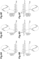
FIGS. 3A, 3B, and 3C are diagrams illustrating a demagnetization magnetic flux synchronized with rotation of a rotor. -
FIG. 4 is a diagram for explaining demagnetization of a magnet of the rotor by an external magnetic flux. -
FIG. 5 is a flowchart illustrating an operation of a controller inFIG. 1 . -
FIGS. 6A and 6B are diagrams illustrating a current provided from a power converter to the electric machine in the electric machine system of a second embodiment.FIGS. 6C, 6D, 6E, and 6F are diagrams illustrating modification examples of the current provided from the power converter to the electric machine in the electric machine system of the second embodiment. -
FIG. 7 is a diagram for explaining demagnetization of a magnet of the rotor by heat. -
FIGS. 8A and 8B are other diagrams illustrating the current provided from the power converter to the electric machine in the electric machine system of the second embodiment.FIGS. 8C, 8D, 8E, and 8F are other diagrams illustrating modification examples of the current provided from the power converter to the electric machine in the electric machine system of the second embodiment. - An electric machine system of the present disclosure includes an electric machine including a rotor that includes a magnet and rotates together with a shaft, and a coil fixedly disposed to surround the rotor; a power converter that outputs an output current to the coil of the electric machine; and a controller that controls the power converter. The controller includes a signal output unit that outputs a signal for controlling a mode of the output current to the power converter, and an abnormality detection unit that receives an abnormality signal indicating an abnormal situation. The signal output unit outputs a demagnetization control signal to the power converter when the abnormality detection unit receives the abnormality signal. The power converter causes a demagnetization current for a demagnetization magnetic flux for demagnetizing the magnet of the rotor to flow through the coil in response to an input of the demagnetization control signal.
- The controller that has detected the abnormal situation generates a demagnetization magnetic flux for demagnetizing the magnet of the rotor by the coil of the stator by controlling the power converter. When the magnet of the rotor is demagnetized, the magnitude of the fault current generated in the coil of the stator may be reduced. The electric machine system of the present disclosure may reduce the magnitude of the fault current by controlling the power converter originally provided.
- In the above-described electric machine system, the power converter may cause the demagnetization current for the demagnetization magnetic flux including a first demagnetization magnetic flux component in a direction opposite to a direction of a magnetic field generated by the magnet and synchronized with rotation of the magnet to flow through the coil in response to the input of the demagnetization control signal. According to this configuration, the first demagnetization magnetic flux component generated by the coil acts as an external magnetic flux on the magnet of the rotor. As a result, the magnet of the rotor may be demagnetized by the external magnetic flux.
- In the above-described electric machine system, the power converter may perform control such that a current flowing through a coil at a position where a d-axis component is larger than a q-axis component with respect to the rotor among coils surrounding the rotor becomes larger than a current flowing through a coil at a position where the q-axis component is larger than the d-axis component in response to the input of the demagnetization control signal. This operation may also reduce the magnitude of the fault current.
- In the above-described electric machine system, the power converter may cause a current not to flow through a coil at a position where a q-axis component is larger than a d-axis component.
- In the above-described electric machine system, the intensity of the demagnetization magnetic flux including the first demagnetization magnetic flux component may be the intensity that causes irreversible demagnetization of the magnet of the rotor. This configuration may also reduce the magnitude of the fault current.
- In the above-described electric machine system, the demagnetization control signal may cause the power converter to output, to the coil, the demagnetization current for the demagnetization magnetic flux including a second demagnetization component of an alternating current interlinked with the magnet of the rotor. According to this configuration, heat is generated in the magnet of the rotor by the second demagnetization magnetic flux component interlinked with the magnet of the rotor. As a result, the magnet of the rotor may be demagnetized by heat.
- In the above-described electric machine system, the controller may include a demagnetization evaluation unit that evaluates a degree of irreversible demagnetization of the magnet of the rotor. The demagnetization evaluation unit may stop output of the demagnetization control signal from the signal output unit in a case where a degree of irreversible demagnetization of the magnet of the rotor is equal to or less than a threshold value. According to this configuration, the magnitude of the fault current may be reduced without continuing to provide a demagnetization current.
- In the above-described electric machine system, the shaft may be connected to a rotating mechanism of a prime mover at a position different from a position where the rotor is provided. The shaft may receive power transmitted from the rotating mechanism to rotate the rotor. The electric machine may generate electric power due to rotation of the rotor. The electric machine system of the present disclosure may reduce the magnitude of the fault current that may be generated in the electric machine that generates electric power by controlling the power converter originally provided.
- Hereinafter, an electric machine system of the present disclosure will be described in detail with reference to the accompanying drawings. In the description of the drawings, the same elements will be given the same reference numerals, and redundant description thereof will be omitted.
- As shown in
FIG. 1 , theelectric machine system 1 includes anelectric machine 2, apower converter 3, and acontroller 4. Theelectric machine 2 includes a coil and a magnet. Theelectric machine 2 is a generator. Theelectric machine 2 receives kinetic energy from anexternal device 6 and generates electric energy. Theelectric machine 2 may be an electric motor. The electric motor receives electric energy from the outside and generates kinetic energy. In the present disclosure, theelectric machine 2 will be described as a generator. - The
electric machine 2 includes arotor 21 and astator 22 as main components. Therotor 21 is a cylindrical member. Therotor 21 is fixed to ashaft 5. Both ends of theshaft 5 are supported bybearings 23. Therotor 21 rotates integrally with theshaft 5. As shown inFIG. 2 , therotor 21 includes apermanent magnet 211 and anarmour ring 212. Note that thearmour ring 212 may be provided as necessary. Therefore, thearmour ring 212 may be omitted from therotor 21. The cylindricalpermanent magnet 211 is fixed to theshaft 5. Thepermanent magnet 211 may be, for example, a surface permanent magnet. As a result, two axes along the radial direction may be defined in thepermanent magnet 211. A line connecting an N-pole and an S-pole of thepermanent magnet 211 is defined as a d-axis. A q-axis is defined as an axis orthogonal to a d-axis. Thepermanent magnet 211 may be covered by acylindrical armour ring 212. Thestator 22 is disposed around therotor 21. Thestator 22 is fixed to a housing or the like of theelectric machine 2. Thestator 22 does not move with respect to the housing or the like of theelectric machine 2. Thestator 22 includes a plurality ofcoils 221 formed by winding conductive wires around teeth. - Refer to
FIG. 1 again. Thepower converter 3 may also convert AC power into DC power. Thepower converter 3 may also convert DC power into AC power. When theelectric machine 2 is a generator, thepower converter 3 receives electric power from theelectric machine 2. Thepower converter 3 converts a mode of the received power. Thepower converter 3 outputs the converted power to aloading device 7. Thepower converter 3 may also perform phase control related to the phase of the three-phase alternating current. Thepower converter 3 may advance the phase of the three-phase alternating current. Thepower converter 3 may also delay the phase of the three-phase alternating current. - In an
electric machine 2 exemplified as a generator, the input end of theshaft 5 is connected to the external device 6 (prime mover) as a driving source. The input end may be switchable between connection and disconnection with respect to the rotating mechanism which is the output end of theexternal device 6. The input end may be connected to the output end of theexternal device 6 not to be disconnected. When theexternal device 6 rotates theshaft 5, therotor 21 rotates according to the rotation of theshaft 5. Theelectric machine 2 outputs three-phase AC power due to the rotation of therotor 21. - The
controller 4 controls the operation of thepower converter 3. Thecontroller 4 outputs a control signal to thepower converter 3. Thecontroller 4 is connected to thepower converter 3 in a wired or wireless manner. Thecontroller 4 is also connected to a device different from thepower converter 3 in order to obtain information for outputting a control signal. For example, thecontroller 4 may be connected to theelectric machine 2. Theelectric machine 2 may be provided with several sensors. Thecontroller 4 may obtain sensor signals output from these sensors. - Specifically, the
controller 4 receives an abnormality signal θ1 and a current signal θ2 as input signals. Thecontroller 4 outputs an operation control signal ϕ1 and a demagnetization control signal ϕ2 as output signals. - The
controller 4 is realized by a computer. Thecontroller 4 includes one or more computers. A computer includes an arithmetic unit (processor), a main storage unit, an auxiliary storage unit, a communication control unit, an input device, and an output device. Thecontroller 4 is configured by one or a plurality of computers configured by the hardware and software such as a program. In a case where thecontroller 4 includes a plurality of computers, these computers may be locally connected. The plurality of computers constituting thecontroller 4 may be connected via a communication network such as the Internet or an intranet. By this connection, onecontroller 4 is logically constructed. - The
controller 4 has several functional components realized by executing a program on the above hardware. Thecontroller 4 includes anabnormality detection unit 41, asignal output unit 42, and ademagnetization evaluation unit 43 as functional components. - The
abnormality detection unit 41 receives the abnormality signal θ1. The abnormality signal θ1 indicates that theelectric machine 2 is not in a normal operation state. Specifically, the abnormality signal θ1 indicates that an abnormality such as a short circuit occurs in thecoil 221 of theelectric machine 2. The abnormality signal θ1 may be input from, for example, a current sensor that senses a current generated by an abnormality. The abnormality signal θ1 may be input from, for example, a sensor that detects heat or light generated by a short circuit. The abnormality signal θ1 may be input from, for example, a magnetic sensor. That is, the abnormality signal θ1 may be input from various sensors. The abnormality signal θ1 may be output by a processing device that has received output signals from these sensors. The processing device receives an output signal from the sensor. The processing device executes predetermined signal processes on the received signal. As a result, the processing device generates a processed signal. The processing device may output the processed signal as the abnormality signal θ1. The abnormality signal θ1 may be a signal that is determined by human visual observation that an abnormality has occurred and is input to theabnormality detection unit 41 by a human through an input device. Thecontroller 4 including theabnormality detection unit 41 switches the operation of theelectric machine 2 to the operation when the abnormality occurs due to the input of the abnormality signal θ1. - The situation in which the abnormality signal θ1 is input to the
controller 4 is not limited to the short circuit. For example, the abnormality signal θ1 may be input to thecontroller 4 due to a decrease in the supply amount of the refrigerant for cooling theelectric machine 2. For example, the abnormality signal θ1 may be input to thecontroller 4 due to supply abnormality such as clogging of the refrigerant. As a result, demagnetization of thepermanent magnet 211 described later may be performed. - The
electric machine 2 of the present disclosure may be, for example, a generator mounted on an aircraft. Theexternal device 6 such as an internal combustion engine (prime mover) is mounted on the aircraft in addition to theelectric machine 2. Theexternal device 6 includes a rotating body such as a turbine. Theshaft 5 of theelectric machine 2 is directly connected to the rotating body of theexternal device 6. Therefore, therotor 21 rotates with the rotation of the rotating body of theexternal device 6. As a result, a current is generated in thecoil 221. Even when an abnormality such as a short circuit occurs in thecoil 221, it is difficult for theexternal device 6 such as an internal combustion engine to stop immediately. Therefore, even when an abnormality occurs, the rotational power continues to be transmitted from theexternal device 6 to therotor 21 via theshaft 5. - The
signal output unit 42 outputs either the operation control signal ϕ1 or the demagnetization control signal ϕ2 to thepower converter 3. Thesignal output unit 42 outputs the demagnetization control signal ϕ2 in response to theabnormality detection unit 41 receiving the abnormality signal. Conversely, thesignal output unit 42 outputs the operation control signal ϕ1 when theabnormality detection unit 41 does not receive the abnormality signal. - The operation control signal ϕ1 is for operating the
electric machine 2 as a generator. As long as theelectric machine 2 is brought into a desired operation state, the operation of thepower converter 3 realized by the operation control signal ϕ1 is not limited at all. - For example, when the
electric machine 2 is an interior permanent magnet (IPM) motor, thepower converter 3 that has received the operation control signal ϕ1 may output a current including a d-axis component and a q-axis component. When theelectric machine 2 is a surface permanent magnet (SPM) motor, thepower converter 3 that has received the operation control signal ϕ1 may output a current including a q-axis component. The current including a q-axis component ideally means that the current output from thepower converter 3 includes only a q-axis component and does not include a d-axis component. However, in practice, the current output from thepower converter 3 may include a q-axis component as a main component, and may slightly include a d-axis component. - The demagnetization control signal ϕ2 is for causing the
permanent magnet 211 of therotor 21 to be demagnetized. - As described above, the abnormality signal θ1 has been described as indicating that an abnormality such as a short circuit has occurred. When the current (fault current) continues to be generated in the
coil 221 in this abnormal state, an unintended failure may be caused. For example, when theelectric machine 2 is cooled by oil, there is a concern that the oil ignites from a short circuit current. There is also a concern that wear occurs in the peripheral device due to heat generation accompanying the short circuit. When an abnormality occurs in the supply of the refrigerant, there is a concern that the peripheral device is worn due to heat generation caused by a fault current flowing through thecoil 221. Therefore, it is necessary to take measures to cope with the fault current. - When an abnormality such as a short circuit occurs, when the magnetic flux by the
permanent magnet 211 of therotor 21 rotates while interlinking with thecoil 221, a reverse voltage is induced in thecoil 221. As a result, a current is generated in thecoil 221. That is, when therotor 21 rotates, the reverse voltage is not induced in thecoil 221 if the magnetic flux is not interlinked with thecoil 221. That is, no fault current is generated in thecoil 221. Therefore, theelectric machine system 1 of the present disclosure demagnetizes thepermanent magnet 211 of therotor 21. When thepermanent magnet 211 is demagnetized, the magnetic flux interlinked with thecoil 221 decreases. As a result, the magnitude of the induced voltage and the magnitude of the fault current generated in thecoil 221 are suppressed. Further, when thepermanent magnet 211 is demagnetized completely, there is no magnetic flux interlinked with thecoil 221. As a result, no induced voltage is generated in thecoil 221, and no fault current is generated. - The demagnetization of the
permanent magnet 211 may be generated by several factors. In the first embodiment, an example of using demagnetization by an external magnetic flux will be described. In the second embodiment, an example of using demagnetization by heat will be described. - The
power converter 3 that has received the demagnetization control signal ϕ2 outputs a demagnetization current to thestator 22. Thestator 22 that has received the demagnetization current generates a demagnetization magnetic flux D3 (refer toFIG. 3 ). The demagnetization magnetic flux D3 includes a first demagnetization magnetic flux component in a direction opposite to the direction of a magnet magnetic flux D2 generated by thepermanent magnet 211. The demagnetization current that causes the demagnetization magnetic flux D3 may also be referred to as a d-axis current. In other words, the first demagnetization magnetic flux component is along the d-axis. The demagnetization current that generates the demagnetization magnetic flux D3 may include a d-axis current as a main component. That is, the demagnetization current that generates the demagnetization magnetic flux D3 may additionally include a q-axis current. The demagnetization magnetic flux D3 is synchronized with the rotation of thepermanent magnet 211. That is, the demagnetization magnetic flux D3 including the first demagnetization magnetic flux component is a rotating magnetic field. As a result, as shown inFIGS. 3A, 3B, and 3C , the direction of the demagnetization magnetic flux D3 synchronized with the rotation of therotor 21 is always opposite to the direction of the magnet magnetic flux D2 of thepermanent magnet 211. From the viewpoint of thepermanent magnet 211, thepermanent magnet 211 seems to always receive the magnetic flux in the direction opposite to the direction of the magnet magnetic flux D2 generated by itself. The magnitude of the demagnetization magnetic flux D3 is constant. That is, the first demagnetization magnetic flux component included in the demagnetization magnetic flux D3 is synchronized with the rotation of therotor 21. On the other hand, basically, the magnitude of the first demagnetization magnetic flux component does not need to change with the lapse of time. - In other words, the magnitude of the first demagnetization magnetic flux component basically may or may not change with the lapse of time.
- The demagnetization magnetic flux D3 may include the first demagnetization magnetic flux component. Therefore, the demagnetization magnetic flux D3 may include a magnetic flux component not along the d-axis. When the demagnetization magnetic flux D3 includes a magnetic flux component not along the d-axis, the direction of the demagnetization magnetic flux D3 in which the first demagnetization magnetic flux component and the magnetic flux component not along the d-axis are combined does not completely match the direction of the d-axis.
- The
permanent magnet 211 that has received the external magnetic flux generates reversible demagnetization and irreversible demagnetization according to the strength of the external magnetic flux. The demagnetization by the demagnetization magnetic flux D3 may be reversible demagnetization. The demagnetization by the demagnetization magnetic flux D3 may be irreversible demagnetization. In the case of reversible demagnetization, the magnitude of the fault current may be reduced when the demagnetization magnetic flux D3 is applied. In the case of irreversible demagnetization, when the degree of demagnetization is large, the occurrence of a fault current may be suppressed even when the application of the demagnetization magnetic flux D3 is stopped. - Whether the demagnetization magnetic flux D3 causes reversible demagnetization or the demagnetization magnetic flux D3 causes irreversible demagnetization may be understood by referring to the magnetization curve shown in
FIG. 4 . When the magnetization curve of thepermanent magnet 211 of therotor 21 is known, reversible demagnetization and irreversible demagnetization may be randomly selected and generated. - The horizontal axis in
FIG. 4 indicates the strength of the magnetic field (H: unit A/m). The vertical axis represents the magnetic flux density (B: unit T). The graph G51 is a B-H curve (magnetic hysteresis curve) indicating the characteristics of thepermanent magnet 211. The B-H curve indicates the magnetic flux density obtained by summing the external magnetic flux and the magnetic flux of thepermanent magnet 211. The graph G52 is a J-H curve indicating the characteristics of thepermanent magnet 211. The J-H curve indicates how much the magnitude of the magnetic flux of thepermanent magnet 211 is changed by the external magnetic flux. - Now, it is assumed that the state of the
permanent magnet 211 is the operating point P51 on the B-H curve (graph G51). The operating point P51 is the operating point P52 on the J-H curve (graph G52). Next, a straight line G53 connecting the operating point P52 and the original point is determined. Next, it is assumed that a demagnetization magnetic flux D3 as an external magnetic flux of which intensity is Hs is applied to thepermanent magnet 211. As a result, the operating point P52 on the J-H curve (graph G52) changes to the operating point P53. The operating point P53 on the J-H curve (graph G52) is the operating point P54 on the B-H curve. When the application of the demagnetization magnetic flux D3 is stopped at the operating point P54, the magnetic field of thepermanent magnet 211 tries to return to the original state following the straight line G55. The straight line G55 has a slope corresponding to the B-H curve (graph G51). Then, the state of thepermanent magnet 211 may not return to the original operating point P51. The state of thepermanent magnet 211 returns to the intersection point (operating point P55) of the straight line G55 connecting the original operating point P51 and the original point. The magnetic flux density of the operating point P55 is smaller than the magnetic flux density of the original operating point P51. That is, irreversible demagnetization occurs in thepermanent magnet 211. - It may be seen that irreversible demagnetization occurs in the
permanent magnet 211 when the demagnetization magnetic flux D3 with which the state change on the J-H curve (graph G52) exceeds the break point P56 of the J-H curve is applied to thepermanent magnet 211. - The
demagnetization evaluation unit 43 may evaluate the state of demagnetization of thepermanent magnet 211 of therotor 21 using, for example, the magnitude of a fault current generated in thecoil 221. The demagnetization state indicates, for example, a state of thepermanent magnet 211 in which a fault current smaller than an allowable current value occurs. For example, during the period in which the demagnetization control signal ϕ2 is output, thepermanent magnet 211 is sufficiently demagnetized. Next, the output of the demagnetization control signal ϕ2 is stopped for a predetermined period. Then, demagnetization of thepermanent magnet 211 due to the application of the demagnetization magnetic flux D3 does not occur. The magnitude of the magnetic flux generated by thepermanent magnet 211 is reduced by irreversible demagnetization. In thecoil 221, a fault current corresponding to the magnitude of the magnetic flux density reduced by the irreversible demagnetization is generated. When the intensity of the magnetic flux is sufficiently reduced by the irreversible demagnetization, it is not necessary to continue to apply the demagnetization magnetic flux D3. That is, when the magnitude of the fault current is acceptable, it is not necessary to continue to apply the demagnetization magnetic flux D3. Therefore, thedemagnetization evaluation unit 43 stops the application of the demagnetization magnetic flux D3 for a predetermined period after applying the demagnetization magnetic flux D3. Thedemagnetization evaluation unit 43 obtains the magnitude of the fault current generated in a state where the application of the demagnetization magnetic flux D3 is stopped. Then, thedemagnetization evaluation unit 43 selects continuation or stop of the application of the demagnetization magnetic flux D3 according to the magnitude of the fault current. - Note that the above is an example of a case where a current sensor that detects the magnitude of the current generated in the
coil 221 is mounted. For example, in a case where a sensor that detects heat or light is mounted, thedemagnetization evaluation unit 43 may stop the application of the demagnetization magnetic flux D3 on condition that the sensor does not detect an abnormal state and does not output an abnormality signal. Alternatively, thedemagnetization evaluation unit 43 may determine whether to stop the application of the demagnetization magnetic flux D3 by using the result of measuring the magnetic flux of the interlinked rotors. - In a case where the
electric machine 2 includes a sensor that directly measures the magnitude of the magnetic field of thepermanent magnet 211, thedemagnetization evaluation unit 43 may select continuation or stop of the application of the demagnetization magnetic flux D3 by comparing the measurement value with a threshold value. In this case, an operation of stopping the demagnetization current for a predetermined period is unnecessary. - Next, the operation of the
controller 4 will be described with reference to the flowchart shown inFIG. 5 . First, thesignal output unit 42 outputs the operation control signal ϕ1 (S1). Next, theabnormality detection unit 41 determines whether the abnormality signal θ1 is input (S2). In a case where there is no input of the abnormality signal θ1 (S2: NO), the presence or absence of the input of the abnormality signal θ1 is determined again after a predetermined standby period. That is, the operation of determining the presence or absence of the input of the abnormality signal θ1 and the standby operation are repeated until the input of the abnormality signal θ1 occurs. - When the abnormality signal θ1 is input (S2: YES), the
signal output unit 42 stops the output of the operation control signal ϕ1 and starts the output of the demagnetization control signal ϕ2 (S3). The intensity of the demagnetization magnetic flux D3 determined by the demagnetization control signal ϕ2 may be determined by a demagnetization mode (reversible demagnetization, irreversible demagnetization, or complete demagnetization). The demagnetization magnetic flux D3 is synchronized with the rotation of therotor 21. It is difficult to directly detect the rotation of therotor 21 in the abnormal state. Therefore, thesignal output unit 42 may perform feedback control of the phase of the demagnetization magnetic flux D3 to reduce the magnitude of the fault current. - As an example, the
power converter 3 that has received the input of the demagnetization control signal ϕ2 may perform control such that a current flowing through a coil at a position where a d-axis component is larger than a q-axis component with respect to therotor 21 amongcoils 221 surrounding therotor 21 becomes larger than a current flowing through the coil at a position where the q-axis component is larger than the d-axis component. Thepower converter 3 may not cause a current to flow through the coil at a position where the q-axis component is larger than the d-axis component. - In other words, the
power converter 3 that has received the input of the demagnetization control signal ϕ2 controls the current flowing through the coil such that the d-axis component is larger than the q-axis component among thecoils 221 surrounding therotor 21. As a result, a state is realized in which the current flowing through the coil at the position where the d-axis component is larger than the q-axis component with respect to therotor 21 is larger than the current flowing through the coil at the position where the q-axis component is larger than the d-axis component. Note that the current may not flow through the coil at a position where the q-axis component is larger than the d-axis component. - Next, the
demagnetization evaluation unit 43 evaluates the degree of demagnetization of the permanent magnet 211 (S4). A specific method of the evaluation is, for example, as described above. In a case where the degree of demagnetization is not sufficient (S4: NO), thedemagnetization evaluation unit 43 continues to output the demagnetization control signal ϕ2. In a case where the degree of demagnetization is sufficient (S4: YES), thedemagnetization evaluation unit 43 stop outputting the demagnetization control signal ϕ2. - Hereinafter, functions and effects of the
electric machine system 1 according to the first embodiment will be described. - The
electric machine system 1 includes theelectric machine 2 including therotor 21 that includes thepermanent magnet 211 and rotates together with theshaft 5 and thecoil 221 fixedly disposed to surround therotor 21; thepower converter 3 that outputs an output current to thecoil 221 of theelectric machine 2; and thecontroller 4 that controls thepower converter 3. Thecontroller 4 includes thesignal output unit 42 that outputs a signal for controlling a mode of the output current to thepower converter 3; and theabnormality detection unit 41 that receives an abnormality signal θ1 indicating an abnormal situation in a case of the abnormal situation in which the generation of the fault current generated in thecoil 221 by the rotation of therotor 21 should be suppressed. When theabnormality detection unit 41 receives the abnormality signal θ1, thesignal output unit 42 outputs the demagnetization control signal ϕ2 to thepower converter 3. The demagnetization control signal ϕ2 causes thepower converter 3 to output, to thecoil 221, a demagnetization current for a demagnetization magnetic flux D3 that demagnetizes thepermanent magnet 211 of therotor 21. - The
controller 4 that has detected the abnormal situation gives the demagnetization magnetic flux D3 for demagnetizing thepermanent magnet 211 of therotor 21 to thecoil 221 of thestator 22 by controlling thepower converter 3. When thepermanent magnet 211 of therotor 21 is demagnetized, the magnitude of the fault current generated in thecoil 221 of thestator 22 may be suppressed. Theelectric machine system 1 may reduce the magnitude of the fault current by controlling thepower converter 3 originally provided. - The
electric machine system 1 of the present disclosure does not include a circuit breaker provided in an electrical output path of theelectric machine 2. Theelectric machine system 1 is not equipped with other devices for taking measures against a fault current, such as a clutch that physically interrupts the rotation of theshaft 5. Therefore, theelectric machine system 1 may reduce the weight of theelectric machine system 1 as compared with a system equipped with such an interrupting device. In theelectric machine system 1 of the present disclosure, thecontroller 4 that controls the power generation or the operation of theelectric machine 2 in the normal state takes a measure against occurrence of an abnormality. - In other words, the
electric machine system 1 applies a reverse magnetic field to thepermanent magnet 211 of therotor 21 by utilizing a current control function of an inverter or a converter that drives theelectric machine 2 when a failure of the generator that is theelectric machine 2 is detected. As a result, since thepermanent magnet 211 is demagnetized partially or completely, a power generation function that generates a fault current may be reduced or eliminated. Therefore, a large fault current may be suppressed from continuing to flow. - The
electric machine system 1 includes a fault protection system regardless of the presence or absence of additional components such as a circuit breaker and a clutch. Furthermore, a safety device provided separately from theelectric machine 2 such as a circuit breaker may not cope with an internal short circuit failure inside theelectric machine 2. However, theelectric machine system 1 may also cope with an internal short circuit failure inside theelectric machine 2. When additional components are not provided, an increase in the number of parts constituting theelectric machine system 1 is also suppressed. As a result, the maintainability of theelectric machine system 1 may also be improved. - The direction of the demagnetization magnetic flux D3 generated by the demagnetization control signal ϕ2 is opposite to the direction of the magnet magnetic flux D2 generated by the
permanent magnet 211. Thepower converter 3 outputs a demagnetization current for the demagnetization magnetic flux D3 including the first demagnetization magnetic flux component synchronized with the rotation of thepermanent magnet 211 to thecoil 221. According to this configuration, the first demagnetization magnetic flux component generated by thecoil 221 acts as an external magnetic flux on thepermanent magnet 211 of therotor 21. As a result, the magnet of therotor 21 may be demagnetized by the external magnetic flux. - The intensity of the demagnetization magnetic flux D3 including the first demagnetization magnetic flux component is an intensity that causes irreversible demagnetization of the
permanent magnet 211 of therotor 21. This configuration may also reduce the magnitude of the fault current. - The
controller 4 includes thedemagnetization evaluation unit 43 that evaluates the degree of irreversible demagnetization of thepermanent magnet 211 of therotor 21. When the degree of irreversible demagnetization of thepermanent magnet 211 of therotor 21 is equal to or less than the threshold value, thedemagnetization evaluation unit 43 stops the output of the demagnetization control signal ϕ2 from thesignal output unit 42. According to this configuration, the fault current may be suppressed without continuing to provide the demagnetization current. - The
electric machine system 1 according to the second embodiment will be described. Theelectric machine system 1 of the second embodiment is different from that of the first embodiment in the principle adopted for demagnetization. Therefore, since physical components of theelectric machine system 1 are the same as those in the first embodiment, detailed description thereof will be omitted. Theelectric machine system 1 of the second embodiment is different from that of the first embodiment in the operation of thepower converter 3 according to the demagnetization control signal ϕ2 generated by thesignal output unit 42 of thecontroller 4 and the operation of thestator 22. Specifically, thecontroller 4 of the first embodiment demagnetizes thepermanent magnet 211 of therotor 21 by the external magnetic flux. Thecontroller 4 of the second embodiment demagnetizes thepermanent magnet 211 of therotor 21 by heat. That is, the demagnetization control signal ϕ2 output from thecontroller 4 of the second embodiment generates a magnetic field that heats thepermanent magnet 211 of therotor 21. -
FIG. 6A illustrates a demagnetization current output to thestator 22 by thepower converter 3 that has received the demagnetization control signal ϕ2. As shown inFIG. 6A , the demagnetization current is an alternating current. The demagnetization current shown inFIG. 6A includes an AC component of which the magnitude changes to a plus side and a minus side across zero. The demagnetization current does not include a DC component (bias component) that does not change with the lapse of time. As a result, demagnetization magnetic flux D3 is also an alternating magnetic field in which the magnitude of the magnetic field changes with the lapse of time. By applying an alternating magnetic field to therotor 21, eddy currents may be intentionally generated in therotor 21. This eddy current causes the magnet to generate heat. - As shown in
FIG. 6B , the demagnetization current may include an AC component. The demagnetization current may include a DC component in addition to an AC component. When the demagnetization current includes an AC component and a DC component, the switching frequency may be lowered. As a result, an effect of increasing the eddy current based on the high-frequency ripple current (refer to the enlarged portion ofFIG. 6B ) may also be obtained. - The technique for lowering the switching frequency is not limited to the example shown in
FIG. 6B . The technique for lowering the switching frequency is also applicable to the example ofFIG. 6A . Furthermore, the technique for lowering the switching frequency may also be applied to exemplary operations shown inFIGS. 6C, 6D, 6E, and 6F described later. According to the technique for lowering the switching frequency, since a high-frequency component is included, the heating effect may be enhanced. -
FIG. 8A also illustrates the demagnetization current output to thestator 22 by thepower converter 3 that has received the demagnetization control signal ϕ2. As shown inFIG. 8A , the demagnetization current is an alternating current. The demagnetization current shown inFIG. 8A includes an AC component of which the magnitude changes to a plus side and a minus side across zero. The demagnetization current shown inFIG. 8A does not include a DC component (bias component) that does not change with the lapse of time. As a result, demagnetization magnetic flux D3 is also an alternating magnetic field in which the magnitude of the magnetic field changes with the lapse of time. By applying an alternating magnetic field to therotor 21, eddy currents may be intentionally generated in therotor 21. This eddy current causes the magnet to generate heat. - As shown in
FIG. 8B , the demagnetization current may include an AC component. The demagnetization current may include a DC component in addition to an AC component. In particular, inFIG. 8B , the sign of the combined current of the AC component and the DC component does not vary with time. That is, the sign of the combined current may be always positive or always negative. - In the example shown in
FIGS. 8A and 8B , the switching frequency may be lowered. As a result, an effect of increasing the eddy current based on the high-frequency ripple current may also be obtained. The high-frequency ripple current is shown in an enlarged portion ofFIGS. 8A and 8B as an example. - The technique for lowering the switching frequency is not limited to the example illustrated in
FIGS. 8A and 8B . The technique for lowering the switching frequency may also be applied to exemplary operations shown inFIGS. 8C, 8D, 8E, and 8F described later. According to the technique for lowering the switching frequency, since a high-frequency component is included, the heating effect may be enhanced. - In the demagnetization by the external magnetic flux, reversible demagnetization and irreversible demagnetization may be intentionally selected when the magnetization characteristics of the
permanent magnet 211 as shown inFIG. 4 are known. Similarly, the reversible demagnetization and the irreversible demagnetization may be intentionally selected when the magnetization characteristics of thepermanent magnet 211 are known. -
FIG. 7 illustrates a B-H curve indicating the magnetization characteristics of thepermanent magnet 211. A B-H curve shown in the graph G71 indicates the magnetization characteristics of thepermanent magnet 211 when the temperature of thepermanent magnet 211 is room temperature. A B-H curve shown in the graph G72 indicates the magnetization characteristics of thepermanent magnet 211 when the temperature of thepermanent magnet 211 is high. As shown in the graphs G71 and G72, the magnetization characteristics of thepermanent magnet 211 changes depending on the temperature. - It is assumed that the temperature of the
permanent magnet 211 is room temperature and in a state of the operating point P71. Next, it is assumed that as a result of thepermanent magnet 211 being heated, the magnetization characteristics of thepermanent magnet 211 has changed to the characteristics shown in the graph G72. The operating point P72 is determined by the temperature coefficient of the residual magnetic flux density (Br) of thepermanent magnet 211. Now, the straight line G73 may be defined by the temperature coefficient of the residual magnetic flux density (Br). Thepermanent magnet 211 operates in the state shown on the straight line G73 according to the temperature. That is, the operating point P72 of the heatedpermanent magnet 211 is an intersection of the B-H curve which is the graph G72 and the straight line G73. Looking back on the description of demagnetization in the first embodiment, when the operating point exceeds the break point Ps in the B-H curve, irreversible demagnetization occurs. Similarly, in a case where thepermanent magnet 211 is heated until the characteristics shown in the graph G72 are obtained, irreversible demagnetization occurs. For example, it is assumed that the temperature is higher than room temperature and is the temperature indicated by the B-H curve of the graph G74. In this case, the operating point P73 does not exceed the break point. Therefore, in this case, the magnetization is reversible demagnetization. - The degree of heating of the
permanent magnet 211 may be controlled by, for example, the amplitude and frequency of the AC component. The degree of heating of thepermanent magnet 211 may also be adjusted by controlling the switching speed and changing the magnitude of ripples. - The demagnetization control signal ϕ2 causes the
power converter 3 to output, to thecoil 221, a demagnetization current for a demagnetization magnetic flux including the second demagnetization component of an alternating current interlinked with thepermanent magnet 211 of therotor 21. According to this configuration, heat is generated in thepermanent magnet 211 of therotor 21 by the second demagnetization magnetic flux component interlinked with thepermanent magnet 211 of therotor 21. As a result, thepermanent magnet 211 of therotor 21 may be demagnetized by heat. - The electric machine system of the present disclosure has been described above in detail based on the embodiment. However, the electric machine system of the present disclosure is not limited to the above contents. The electric machine system of the present disclosure may be variously modified without departing from the gist thereof.
- In the second embodiment, as shown in
FIGS. 6A and 6B , the demagnetization current has been described as a d-axis current. For example, the demagnetization current may be a q-axis current as shown inFIG. 6C . The demagnetization current, which is a q-axis current, may include only an AC component as shown inFIG. 6C . The demagnetization current, which is a q-axis current, may include an AC component and a DC component as shown inFIG. 6D . - As shown in
FIG. 6E , the demagnetization current may be a combined current of a d-axis current component and a q-axis current component. Also in this case, similarly to Modification Example 1, the demagnetization current which is a dq-axis combined current may include only an AC component as shown inFIG. 6E . The demagnetization current, which is the dq-axis combined current, may include an AC component and a DC component as shown inFIG. 6F . - The present disclosure includes the following configurations.
- The electric machine system of the present disclosure is [1] "an electric machine system including: an electric machine including a rotor that includes a magnet and rotates together with a shaft, and a coil fixedly disposed to surround the rotor; a power converter configured to output an output current to the coil of the electric machine; and a controller that controls the power converter, in which the controller includes a signal output unit configured to output a signal for controlling a mode of the output current to the power converter, and an abnormality detection unit configured to receive an abnormality signal indicating an abnormal situation, the signal output unit outputs a demagnetization control signal to the power converter when the abnormality detection unit receives the abnormality signal, and the power converter causes a demagnetization current for a demagnetization magnetic flux for demagnetizing the magnet of the rotor to flow through the coil in response to an input of the demagnetization control signal".
- The electric machine system of the present disclosure is [2] "the electric machine system according to the above-described [1], in which the power converter causes the demagnetization current for the demagnetization magnetic flux including a first demagnetization magnetic flux component in a direction opposite to a direction of a magnetic field generated by the magnet and synchronized with rotation of the magnet to flow through the coil in response to the input of the demagnetization control signal".
- The electric machine system of the present disclosure is [3] "the electric machine system according to the above-described [2], in which the power converter performs control such that a current flowing through a coil at a position where a d-axis component is larger than a q-axis component with respect to the rotor among coils surrounding the rotor becomes larger than a current flowing through a coil at a position where the q-axis component is larger than the d-axis component in response to the input of the demagnetization control signal".
- The electric machine system of the present disclosure is [4] "the electric machine system according to the above-described [3], in which the power converter causes a current not to flow through a coil at a position where a q-axis component is larger than a d-axis component".
- The electric machine system of the present disclosure is [5] "the electric machine system according to any one of the above-described [2] to [4], in which the intensity of the demagnetization magnetic flux including the first demagnetization magnetic flux component is an intensity that causes irreversible demagnetization of the magnet of the rotor".
- The electric machine system of the present disclosure is [6] "the electric machine system according to any one of the above-described [1] to [5], in which the demagnetization control signal causes the power converter to output, to the coil, the demagnetization current for the demagnetization magnetic flux including a second demagnetization component of an alternating current interlinked with the magnet of the rotor".
- The electric machine system of the present disclosure is [7] "the electric machine system according to any one of the above-described [1] to [6], in which the controller includes a demagnetization evaluation unit that evaluates a degree of irreversible demagnetization of the magnet of the rotor, and the demagnetization evaluation unit stops output of the demagnetization control signal from the signal output unit in a case where a degree of irreversible demagnetization of the magnet of the rotor is equal to or less than a threshold value".
- The electric machine system of the present disclosure is [8] "the electric machine system according to any one of the above-described [1] to [7], in which the shaft is connected to a rotating mechanism of a prime mover at a position different from a position where the rotor is provided, the shaft receives power transmitted from the rotating mechanism to rotate the rotor, and the electric machine generates electric power due to rotation of the rotor.
-
- 1
- Electric machine system
- 2
- Electric machine
- 3
- Power converter
- 4
- Controller
- 5
- Shaft
- 6
- External device (prime mover)
- 7
- Loading device
- 21
- Rotor
- 22
- Stator
- 23
- Bearing
- 41
- Abnormality detection unit
- 42
- Signal output unit
- 43
- Demagnetization evaluation unit
- 211
- Permanent magnet
- 212
- Armour ring
- D3
- Demagnetization magnetic flux
- θ1
- Abnormality signal
- θ2
- Current signal
- ϕ1
- Operation control signal
- ϕ2
- Demagnetization control signal
Claims (8)
- An electric machine system comprising:an electric machine comprising:a rotor that comprises a magnet and rotates together with a shaft; anda coil fixedly disposed to surround the rotor;a power converter configured to output an output current to the coil of the electric machine; anda controller that controls the power converter,wherein the controller comprises:a signal output unit configured to output a signal for controlling a mode of the output current to the power converter; andan abnormality detection unit configured to receive an abnormality signal indicating an abnormal situation,wherein the signal output unit outputs a demagnetization control signal to the power converter when the abnormality detection unit receives the abnormality signal, andwherein the power converter is configured to cause a demagnetization current for a demagnetization magnetic flux for demagnetizing the magnet of the rotor to flow through the coil, in response to an input of the demagnetization control signal.
- The electric machine system according to claim 1, wherein the power converter causes the demagnetization current for the demagnetization magnetic flux including a first demagnetization magnetic flux component in a direction opposite to a direction of a magnetic field generated by the magnet and synchronized with rotation of the magnet to flow through the coil, in response to the input of the demagnetization control signal.
- The electric machine system according to claim 2, wherein the power converter is configured to perform a control such that a current flowing through a coil at a position where a d-axis component is larger than a q-axis component with respect to the rotor among coils surrounding the rotor becomes larger than a current flowing through a coil at a position where the q-axis component is larger than the d-axis component, in response to the input of the demagnetization control signal.
- The electric machine system according to claim 3, wherein the power converter causes the current not to flow through the coil at the position where the q-axis component is larger than the d-axis component.
- The electric machine system according to claim 2, wherein an intensity of the demagnetization magnetic flux including the first demagnetization magnetic flux component is an intensity that causes an irreversible demagnetization of the magnet of the rotor.
- The electric machine system according to claim 1, wherein the demagnetization control signal causes the power converter to output, to the coil, the demagnetization current for the demagnetization magnetic flux including a second demagnetization component which is an alternating current component interlinked with the magnet of the rotor.
- The electric machine system according to claim 1,wherein the controller comprises a demagnetization evaluation unit that evaluates a degree of irreversible demagnetization of the magnet of the rotor, andwherein the demagnetization evaluation unit stops output of the demagnetization control signal from the signal output unit in a case where the degree of irreversible demagnetization of the magnet of the rotor is equal to or less than a threshold value.
- The electric machine system according to claim 1,wherein the shaft is connected to a rotating mechanism of a prime mover at a position different from a position where the rotor is provided,wherein the shaft receives power transmitted from the rotating mechanism to rotate the rotor, andwherein the electric machine generates electric power due to rotation of the rotor.
Applications Claiming Priority (2)
| Application Number | Priority Date | Filing Date | Title |
|---|---|---|---|
| JP2021153869 | 2021-09-22 | ||
| PCT/JP2022/033137 WO2023047921A1 (en) | 2021-09-22 | 2022-09-02 | Electric machine system |
Publications (2)
| Publication Number | Publication Date |
|---|---|
| EP4344049A1 true EP4344049A1 (en) | 2024-03-27 |
| EP4344049A4 EP4344049A4 (en) | 2025-06-25 |
Family
ID=85720565
Family Applications (1)
| Application Number | Title | Priority Date | Filing Date |
|---|---|---|---|
| EP22872677.4A Pending EP4344049A4 (en) | 2021-09-22 | 2022-09-02 | Electric machine system |
Country Status (5)
| Country | Link |
|---|---|
| US (1) | US20240146223A1 (en) |
| EP (1) | EP4344049A4 (en) |
| JP (2) | JPWO2023047921A1 (en) |
| CN (1) | CN117546403A (en) |
| WO (1) | WO2023047921A1 (en) |
Family Cites Families (12)
| Publication number | Priority date | Publication date | Assignee | Title |
|---|---|---|---|---|
| US7291958B2 (en) * | 2000-05-12 | 2007-11-06 | Reliance Electric Technologies Llc | Rotating back iron for synchronous motors/generators |
| JP4884414B2 (en) * | 2008-03-31 | 2012-02-29 | 三菱電機株式会社 | Self-demagnetization device for permanent magnet motor and method for stopping operation of electrical product |
| JP5178488B2 (en) | 2008-12-16 | 2013-04-10 | 株式会社東芝 | Permanent magnet rotating electric machine |
| JP4403253B1 (en) | 2009-01-14 | 2010-01-27 | 有限会社クラ技術研究所 | Magnetic flux amount variable axial gap rotating electrical machine system |
| GB201005178D0 (en) * | 2010-03-29 | 2010-05-12 | Rolls Royce Plc | Electrical machine safety system |
| JP2012186917A (en) * | 2011-03-04 | 2012-09-27 | Fujitsu Ten Ltd | Motor controller and motor control method |
| JP5616409B2 (en) * | 2012-09-06 | 2014-10-29 | ファナック株式会社 | Control device for permanent magnet synchronous motor for preventing irreversible demagnetization of permanent magnet and control system provided with such control device |
| JP2014117013A (en) * | 2012-12-06 | 2014-06-26 | Toyota Motor Corp | Control device for motor and vehicle with motor mounted therein as drive source |
| WO2016189671A1 (en) * | 2015-05-26 | 2016-12-01 | 日産自動車株式会社 | Motor control device and method for stopping same |
| JP2017112680A (en) * | 2015-12-15 | 2017-06-22 | 日立オートモティブシステムズ株式会社 | Inverter control device |
| KR102518904B1 (en) * | 2018-06-29 | 2023-04-06 | 에이치엘만도 주식회사 | Apparatus and method for controlling motor for vehicle |
| JP2021153869A (en) | 2020-03-27 | 2021-10-07 | サミー株式会社 | Pachinko game machine |
-
2022
- 2022-09-02 JP JP2023549449A patent/JPWO2023047921A1/ja active Pending
- 2022-09-02 WO PCT/JP2022/033137 patent/WO2023047921A1/en not_active Ceased
- 2022-09-02 EP EP22872677.4A patent/EP4344049A4/en active Pending
- 2022-09-02 CN CN202280042237.9A patent/CN117546403A/en active Pending
-
2024
- 2024-01-09 US US18/407,516 patent/US20240146223A1/en active Pending
-
2025
- 2025-02-19 JP JP2025025259A patent/JP7831661B2/en active Active
Also Published As
| Publication number | Publication date |
|---|---|
| CN117546403A (en) | 2024-02-09 |
| US20240146223A1 (en) | 2024-05-02 |
| JP7831661B2 (en) | 2026-03-17 |
| JP2025068064A (en) | 2025-04-24 |
| JPWO2023047921A1 (en) | 2023-03-30 |
| EP4344049A4 (en) | 2025-06-25 |
| WO2023047921A1 (en) | 2023-03-30 |
Similar Documents
| Publication | Publication Date | Title |
|---|---|---|
| US10042011B2 (en) | Method to detect or monitor the demagnetization of a magnet | |
| US11228267B2 (en) | Electric drive device | |
| Rosero et al. | Study on the permanent magnet demagnetization fault in permanent magnet synchronous machines | |
| US20110234180A1 (en) | Electrical machine safety system | |
| JP2008043196A (en) | Failure treatment of inverter drive version pm motor drive unit | |
| EP2403126B1 (en) | Method for operating a wind turbine, method for determining the temperature of a permanent magnet and controller for a wind turbine | |
| JP7235756B2 (en) | System and method for preventing demagnetization of permanent magnets in electrical machines | |
| US9041402B2 (en) | Detecting an abnormality of a switch in a high voltage electrical substation | |
| Li et al. | Thermal-electromagnetic analysis of a fault-tolerant dual-star flux-switching permanent magnet motor for critical applications | |
| Huang et al. | Mitigation of interturn short-circuits in IPMSM by using MTPCC control adaptive to fault severity | |
| Huang et al. | Fault tolerant control for open winding brushless DC motor with power device failure | |
| EP3832327B1 (en) | Electric machine fault detection scheme | |
| US20240146223A1 (en) | Electric machine system | |
| KR102522311B1 (en) | System and method for lock-motor detection of reducer integrated motor | |
| US11799354B2 (en) | Current imbalance fault mitigation for rotary electric machine with parallel stator windings | |
| US8125747B2 (en) | Method for mitigating negative sequence effect resulting from non-symmetrical short circuit failure of synchronous electric machine based systems | |
| US20240372436A1 (en) | Electric machine with an electromagnetic bearing | |
| Sarikhani et al. | Inter-turn fault detection in PM synchronous machines by physics-based EMF estimation | |
| JP2016007113A (en) | Drive unit of compressor | |
| EP1320165A2 (en) | Apparatus and method for protecting synchronus generators against off-nominal frequency deviation and alternating forces excitation | |
| EP4432552A1 (en) | A controller for a permanent magnet machine | |
| JP4822138B2 (en) | Power generation system and operation method thereof | |
| KR20140009941A (en) | Power cabel breaking detection method of inverter system | |
| RU2419953C1 (en) | Motor control device | |
| Jaikrishna et al. | Fault tolerant soft starter control for induction motors |
Legal Events
| Date | Code | Title | Description |
|---|---|---|---|
| STAA | Information on the status of an ep patent application or granted ep patent |
Free format text: STATUS: THE INTERNATIONAL PUBLICATION HAS BEEN MADE |
|
| PUAI | Public reference made under article 153(3) epc to a published international application that has entered the european phase |
Free format text: ORIGINAL CODE: 0009012 |
|
| STAA | Information on the status of an ep patent application or granted ep patent |
Free format text: STATUS: REQUEST FOR EXAMINATION WAS MADE |
|
| 17P | Request for examination filed |
Effective date: 20231218 |
|
| AK | Designated contracting states |
Kind code of ref document: A1 Designated state(s): AL AT BE BG CH CY CZ DE DK EE ES FI FR GB GR HR HU IE IS IT LI LT LU LV MC MK MT NL NO PL PT RO RS SE SI SK SM TR |
|
| DAV | Request for validation of the european patent (deleted) | ||
| DAX | Request for extension of the european patent (deleted) | ||
| REG | Reference to a national code |
Ref country code: DE Ref legal event code: R079 Free format text: PREVIOUS MAIN CLASS: H02P0021220000 Ipc: H02P0021100000 |
|
| A4 | Supplementary search report drawn up and despatched |
Effective date: 20250523 |
|
| RIC1 | Information provided on ipc code assigned before grant |
Ipc: H02P 29/032 20160101ALI20250519BHEP Ipc: H02P 21/10 20160101AFI20250519BHEP |