EP4344035A1 - Resonant hybrid flyback converter with overcurrent detection - Google Patents
Resonant hybrid flyback converter with overcurrent detection Download PDFInfo
- Publication number
- EP4344035A1 EP4344035A1 EP22196463.8A EP22196463A EP4344035A1 EP 4344035 A1 EP4344035 A1 EP 4344035A1 EP 22196463 A EP22196463 A EP 22196463A EP 4344035 A1 EP4344035 A1 EP 4344035A1
- Authority
- EP
- European Patent Office
- Prior art keywords
- flyback converter
- resonant
- primary
- shunt resistor
- side current
- Prior art date
- Legal status (The legal status is an assumption and is not a legal conclusion. Google has not performed a legal analysis and makes no representation as to the accuracy of the status listed.)
- Pending
Links
Images

Classifications
-
- H—ELECTRICITY
- H02—GENERATION; CONVERSION OR DISTRIBUTION OF ELECTRIC POWER
- H02M—APPARATUS FOR CONVERSION BETWEEN AC AND AC, BETWEEN AC AND DC, OR BETWEEN DC AND DC, AND FOR USE WITH MAINS OR SIMILAR POWER SUPPLY SYSTEMS; CONVERSION OF DC OR AC INPUT POWER INTO SURGE OUTPUT POWER; CONTROL OR REGULATION THEREOF
- H02M3/00—Conversion of DC power input into DC power output
- H02M3/22—Conversion of DC power input into DC power output with intermediate conversion into AC
- H02M3/24—Conversion of DC power input into DC power output with intermediate conversion into AC by static converters
- H02M3/28—Conversion of DC power input into DC power output with intermediate conversion into AC by static converters using discharge tubes with control electrode or semiconductor devices with control electrode to produce the intermediate AC
- H02M3/325—Conversion of DC power input into DC power output with intermediate conversion into AC by static converters using discharge tubes with control electrode or semiconductor devices with control electrode to produce the intermediate AC using devices of a triode or a transistor type requiring continuous application of a control signal
- H02M3/335—Conversion of DC power input into DC power output with intermediate conversion into AC by static converters using discharge tubes with control electrode or semiconductor devices with control electrode to produce the intermediate AC using devices of a triode or a transistor type requiring continuous application of a control signal using semiconductor devices only
- H02M3/33569—Conversion of DC power input into DC power output with intermediate conversion into AC by static converters using discharge tubes with control electrode or semiconductor devices with control electrode to produce the intermediate AC using devices of a triode or a transistor type requiring continuous application of a control signal using semiconductor devices only having several active switching elements
- H02M3/33571—Half-bridge at primary side of an isolation transformer
-
- H—ELECTRICITY
- H02—GENERATION; CONVERSION OR DISTRIBUTION OF ELECTRIC POWER
- H02H—EMERGENCY PROTECTIVE CIRCUIT ARRANGEMENTS
- H02H7/00—Emergency protective circuit arrangements specially adapted for specific types of electric machines or apparatus or for sectionalised protection of cable or line systems, and effecting automatic switching in the event of an undesired change from normal working conditions
- H02H7/10—Emergency protective circuit arrangements specially adapted for specific types of electric machines or apparatus or for sectionalised protection of cable or line systems, and effecting automatic switching in the event of an undesired change from normal working conditions for converters; for rectifiers
- H02H7/12—Emergency protective circuit arrangements specially adapted for specific types of electric machines or apparatus or for sectionalised protection of cable or line systems, and effecting automatic switching in the event of an undesired change from normal working conditions for converters; for rectifiers for static converters or rectifiers
- H02H7/1213—Emergency protective circuit arrangements specially adapted for specific types of electric machines or apparatus or for sectionalised protection of cable or line systems, and effecting automatic switching in the event of an undesired change from normal working conditions for converters; for rectifiers for static converters or rectifiers for DC-DC converters
-
- H—ELECTRICITY
- H02—GENERATION; CONVERSION OR DISTRIBUTION OF ELECTRIC POWER
- H02M—APPARATUS FOR CONVERSION BETWEEN AC AND AC, BETWEEN AC AND DC, OR BETWEEN DC AND DC, AND FOR USE WITH MAINS OR SIMILAR POWER SUPPLY SYSTEMS; CONVERSION OF DC OR AC INPUT POWER INTO SURGE OUTPUT POWER; CONTROL OR REGULATION THEREOF
- H02M1/00—Details of apparatus for conversion
- H02M1/0003—Details of control, feedback or regulation circuits
- H02M1/0009—Devices or circuits for detecting current in a converter
-
- H—ELECTRICITY
- H02—GENERATION; CONVERSION OR DISTRIBUTION OF ELECTRIC POWER
- H02M—APPARATUS FOR CONVERSION BETWEEN AC AND AC, BETWEEN AC AND DC, OR BETWEEN DC AND DC, AND FOR USE WITH MAINS OR SIMILAR POWER SUPPLY SYSTEMS; CONVERSION OF DC OR AC INPUT POWER INTO SURGE OUTPUT POWER; CONTROL OR REGULATION THEREOF
- H02M1/00—Details of apparatus for conversion
- H02M1/32—Means for protecting converters other than automatic disconnection
-
- H—ELECTRICITY
- H02—GENERATION; CONVERSION OR DISTRIBUTION OF ELECTRIC POWER
- H02M—APPARATUS FOR CONVERSION BETWEEN AC AND AC, BETWEEN AC AND DC, OR BETWEEN DC AND DC, AND FOR USE WITH MAINS OR SIMILAR POWER SUPPLY SYSTEMS; CONVERSION OF DC OR AC INPUT POWER INTO SURGE OUTPUT POWER; CONTROL OR REGULATION THEREOF
- H02M3/00—Conversion of DC power input into DC power output
- H02M3/01—Resonant DC/DC converters
-
- H—ELECTRICITY
- H05—ELECTRIC TECHNIQUES NOT OTHERWISE PROVIDED FOR
- H05B—ELECTRIC HEATING; ELECTRIC LIGHT SOURCES NOT OTHERWISE PROVIDED FOR; CIRCUIT ARRANGEMENTS FOR ELECTRIC LIGHT SOURCES, IN GENERAL
- H05B45/00—Circuit arrangements for operating light-emitting diodes [LED]
- H05B45/30—Driver circuits
- H05B45/37—Converter circuits
- H05B45/3725—Switched mode power supply [SMPS]
- H05B45/385—Switched mode power supply [SMPS] using flyback topology
-
- H—ELECTRICITY
- H05—ELECTRIC TECHNIQUES NOT OTHERWISE PROVIDED FOR
- H05B—ELECTRIC HEATING; ELECTRIC LIGHT SOURCES NOT OTHERWISE PROVIDED FOR; CIRCUIT ARRANGEMENTS FOR ELECTRIC LIGHT SOURCES, IN GENERAL
- H05B45/00—Circuit arrangements for operating light-emitting diodes [LED]
- H05B45/50—Circuit arrangements for operating light-emitting diodes [LED] responsive to malfunctions or undesirable behaviour of LEDs; responsive to LED life; Protective circuits
-
- Y—GENERAL TAGGING OF NEW TECHNOLOGICAL DEVELOPMENTS; GENERAL TAGGING OF CROSS-SECTIONAL TECHNOLOGIES SPANNING OVER SEVERAL SECTIONS OF THE IPC; TECHNICAL SUBJECTS COVERED BY FORMER USPC CROSS-REFERENCE ART COLLECTIONS [XRACs] AND DIGESTS
- Y02—TECHNOLOGIES OR APPLICATIONS FOR MITIGATION OR ADAPTATION AGAINST CLIMATE CHANGE
- Y02B—CLIMATE CHANGE MITIGATION TECHNOLOGIES RELATED TO BUILDINGS, e.g. HOUSING, HOUSE APPLIANCES OR RELATED END-USER APPLICATIONS
- Y02B20/00—Energy efficient lighting technologies, e.g. halogen lamps or gas discharge lamps
- Y02B20/30—Semiconductor lamps, e.g. solid state lamps [SSL] light emitting diodes [LED] or organic LED [OLED]
Definitions
- the invention relates to a resonant hybrid flyback converter with overcurrent detection and/or protection.
- Hybrid flyback is to be understood “half-bridge circuit supplying a flyback resonant tank”.
- a resonant hybrid flyback converter for LED lighting means with overcurrent detection and/or protection.
- Said resonant hybrid flyback converter comprises a half-bridge, and a flyback resonant tank comprising a transformer with a primary side and a secondary side.
- the half-bridge is configured to supply said primary side.
- the resonant hybrid flyback converter comprises a control unit controlling the operation of switches of the half-bridge and being supplied with a feedback signal from a sensing circuit configured to sense a primary-side current in the flyback resonant tank.
- the half-bridge, the overall circuit and the load or the LED lighting means, respectively are protected from possible damage in the case of an overcurrent event in a particularly efficient and reliable manner.
- the switches of the half-bridge comprise a high-side switch, preferably a first transistor, more preferably a first field-effect transistor, and a low-side switch, preferably a second transistor, more preferably a second field-effect transistor.
- a high-side switch preferably a first transistor, more preferably a first field-effect transistor
- a low-side switch preferably a second transistor, more preferably a second field-effect transistor.
- the primary side comprises a series connection of an optional inductance, preferably an optional leakage inductance, more preferably an optional resonance choke, most preferably a resonance choke implemented in the transformer or as a separate component, a corresponding transformer main inductance and a capacitance, preferably a resonance capacitor.
- an optional inductance preferably an optional leakage inductance, more preferably an optional resonance choke, most preferably a resonance choke implemented in the transformer or as a separate component
- a corresponding transformer main inductance preferably a capacitance, preferably a resonance capacitor.
- the corresponding primary-side current especially flows through said series connection.
- simplicity can be ensured, which leads to a high efficiency.
- the flyback resonant tank especially the primary side, comprises a resistance, preferably a shunt resistor, more preferably a shunt resistor providing a sensing voltage, most preferably a shunt resistor providing a sensing voltage in accordance with the corresponding primary-side current.
- a resistance preferably a shunt resistor, more preferably a shunt resistor providing a sensing voltage, most preferably a shunt resistor providing a sensing voltage in accordance with the corresponding primary-side current.
- current sensing can be implemented in an easy, and thus cost-efficient, manner.
- the series connection further comprises the resistance, preferably the shunt resistor, more preferably the shunt resistor providing the sensing voltage, most preferably the shunt resistor providing the sensing voltage in accordance with the corresponding primary-side current.
- the resistance preferably the shunt resistor, more preferably the shunt resistor providing the sensing voltage, most preferably the shunt resistor providing the sensing voltage in accordance with the corresponding primary-side current.
- complexity can further be reduced, which leads to an increased efficiency.
- a first terminal of the resistance preferably the shunt resistor, more preferably the shunt resistor providing the sensing voltage, most preferably the shunt resistor providing the sensing voltage in accordance with the corresponding primary-side current
- a second terminal of the resistance preferably the shunt resistor, more preferably the shunt resistor providing the sensing voltage, most preferably the shunt resistor providing the sensing voltage in accordance with the corresponding primary-side current
- a voltage potential preferably ground.
- a first terminal of the resistance preferably the shunt resistor, more preferably the shunt resistor providing the sensing voltage, most preferably the shunt resistor providing the sensing voltage in accordance with the corresponding primary-side current, is connected to a sensing terminal.
- the sensing voltage can be provided for further processing in an easy manner, thereby increasing efficiency.
- the resonant hybrid flyback converter is further configured to compare the sensed corresponding primary-side current to a reference preferably with the aid of a comparator especially comprised by the resonant hybrid flyback converter.
- said reference may preferably define the maximum allowed current in an efficient and reliable manner. It is noted that for the case that said reference is exceeded by the sensed signal, an overcurrent event occurred.
- the resonant hybrid flyback converter is further configured to trigger the entering of a constant off-time mode, especially deactivation, of the half-bridge, preferably of the high-side switch and/or the low-side switch, more preferably of the high-side switch and/or the low-side switch depending on the corresponding timing of the respective overcurrent event.
- the half-bridge can fully be switched off in an efficient manner, which allows for a particularly reliable overcurrent protection.
- the resonant hybrid flyback converter is further configured to trigger the entering of a constant on-time mode of the half-bridge, preferably of the high-side switch and/or the low-side switch.
- the high-side switch and the low-side switch can individually be switched in an efficient manner.
- the resonant hybrid flyback converter is further configured to trigger the entering of a burst mode with respect to the half-bridge, preferably a burst mode reducing the corresponding frequency of the respective drive signal of the high-side switch and/or the low-side switch.
- a burst mode allows for a particularly efficient and reliable overcurrent protection.
- the resonant hybrid flyback converter is further configured to trigger the entering of an operational mode preferably after a defined time and/or responsive to a trigger signal.
- said operational mode can preferably be a regular operation mode or an operational mode according to the respective operational mode before the overcurrent event occurred.
- the resonant hybrid flyback converter further comprises the above-mentioned comparator.
- a first input of the comparator is supplied with the corresponding voltage with respect to the resistance, preferably the shunt resistor, more preferably the shunt resistor providing a sensing voltage, most preferably the shunt resistor providing a sensing voltage in accordance with the corresponding primary-side current.
- a second input of the comparator is supplied with a reference voltage.
- an output of the comparator is especially used to trigger the entering of different modes of the resonant hybrid flyback converter.
- the first input can be supplied by or connected to the above-mentioned sensing terminal, thereby reducing complexity, and thus increasing efficiency.
- the resonant hybrid flyback converter further comprises supplying means being configured to be supplied by the secondary side and to supply the LED lighting means as a load.
- the supplying means comprise a switch and/or a diode and/or a capacitance, preferably a capacitor.
- the capacitance, preferably the capacitor is especially connected in parallel to the load.
- the switch and/or the diode is especially connected in series to the load.
- a system comprising a resonant hybrid flyback converter according to the first aspect of the invention or any of its preferred implementation forms thereof, respectively, and LED lighting means being supplied by said resonant hybrid flyback converter.
- the half-bridge, the overall circuit and the load or the LED lighting means, respectively are protected from possible damage in the case of an overcurrent event in a particularly efficient and reliable manner.
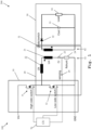
- Fig. 1 illustrates an exemplary embodiment of the inventive resonant hybrid flyback converter 100 with overcurrent detection and/or protection for LED lighting means 34.
- FIG. 1 also depicts an exemplary embodiment of the inventive system 200 comprising the above-mentioned resonant hybrid flyback converter 100 and the above-mentioned LED lighting means 34, exemplarily illustrated as a load, being supplied by said resonant hybrid flyback converter 100.
- the resonant hybrid flyback converter 100 comprises a half-bridge 10, and a flyback resonant tank 20 comprising a resonant capacitor 23 and a transformer with a primary side 61 and a secondary side 62.
- the half-bridge 10 is configured to supply said primary side 61. Furthermore, the resonant hybrid flyback converter 100 is configured to sense a primary-side current in the flyback resonant tank 20.
- the resonant hybrid flyback converter 100 comprises a control unit 70 controlling the operation of switches 11, 12 of the half-bridge 10 and being supplied with a feedback signal ("sensing" or reference sign 25, respectively) from a sensing circuit (R shunt or reference sign 24, respectively) configured to sense a primary-side current in the flyback resonant tank 20.
- control unit 70 can also be a control and/or processing unit.
- control and/or processing unit will be used, wherein the corresponding features can analogously apply for the control unit 70. Nevertheless, it is also possible that such a control and/or processing unit is employed in addition to the control unit 70.
- the above-mentioned half-bridge 10 comprises a high-side switch 11, exemplarily in the form of a first field-effect transistor, and a low-side switch 12, exemplarily in the form of a second field-effect transistor.
- said field-effect transistors 11 and 12 are exemplarily of an n-channel enhancement type.
- a first terminal, exemplarily a drain terminal, of the first field-effect transistor 11 is connected to a voltage potential, exemplarily a supply voltage
- a second terminal, exemplarily a source terminal, of the first field-effect transistor 11 is connected to a first terminal, exemplarily a drain terminal, of the second field-effect transistor 12.
- a second terminal, exemplarily a source terminal, of said second field-effect transistor 12 is connected to a voltage potential, especially another voltage potential, exemplarily ground.
- the above-mentioned primary side 61 comprises a series connection of a leakage inductance 22, which can be optional or omitted, respectively, a corresponding transformer main inductance 21 and a capacitance 23, exemplarily a resonance capacitor.
- the corresponding primary-side current especially flows through said series connection.
- the flyback resonant tank 20, exemplarily the primary side 61 comprises a resistance, exemplarily a shunt resistor 24 providing a sensing voltage in accordance with the corresponding primary-side current.
- the series connection further comprises said resistance or said shunt resistor 24 providing the sensing voltage in accordance with the corresponding primary-side current, respectively.
- the above-mentioned first terminal, exemplarily the drain terminal, of the second field-effect transistor 12 is connected to a first terminal of the leakage inductance 22, whereas a second terminal of said leakage inductance 22 is connected to a first terminal of the transformer main inductance 21.
- the leakage inductance 22 is omitted, it is noted that the first terminal of the second field-effect transistor 12 is connected to said first terminal of the transformer main inductance 21.
- a second terminal of the transformer main inductance 21 is connected to a first terminal of the above-mentioned capacitance 23, whereas a second terminal of said capacitance 23 is connected to a first terminal of the shunt resistor 24, whereas a second terminal of said shunt resistor 24 providing the sensing voltage in accordance with the corresponding primary-side current is connected to a voltage potential, exemplarily ground.
- the first terminal of the shunt resistor 24 is connected to a sensing terminal 25.
- the resonant hybrid flyback converter 100 is further configured to compare the sensed corresponding primary-side current to a reference preferably with the aid of a comparator, such as comparator 40 of Fig. 2 described below, which can especially be comprised by the resonant hybrid flyback converter 100.
- the resonant hybrid flyback converter 100 is further configured to trigger the entering of a constant off-time mode, especially deactivation, of the half-bridge 10, preferably of the high-side switch 11 and/or the low-side switch 12, more preferably of the high-side switch 11 and/or the low-side switch 12 depending on the corresponding timing of the respective overcurrent event.
- the resonant hybrid flyback converter 100 can further be configured to trigger the entering of a constant on-time mode of the half-bridge 10, preferably of the high-side switch 11 and/or the low-side switch 12.
- the resonant hybrid flyback converter 100 can further be configured to trigger the entering of a burst mode with respect to the half-bridge 10, preferably a burst mode reducing the corresponding frequency of the respective drive signal of the high-side switch 11 and/or the low-side switch 12.
- the resonant hybrid flyback converter 100 can further be configured to trigger the entering of an operational mode, exemplarily a regular operation mode, preferably after a defined time and/or responsive to a trigger signal.
- the resonant hybrid flyback converter 100 may further comprise a control and/or processing unit being especially configured to generate said trigger signal.
- Said control and/or processing unit can also be configured to trigger the entering of at least one of the above-mentioned modes.
- the resonant hybrid flyback converter 100 further comprises supplying means 30 being configured to be supplied by the secondary side 62 and to supply the LED lighting means or the load 34, respectively.
- the supplying means 30 comprise a switch and/or a diode, exemplarily a diode 32, and a capacitance, exemplarily an output capacitor 33.
- the capacitance 33 is exemplarily connected in parallel to the load 34, whereas the diode 32 is exemplarily connected in series to the load 34.
- a first terminal of a transformer secondary inductance 31 is connected to a first terminal, exemplarily an anode terminal, of the diode 32, whereas a second terminal, exemplarily a cathode terminal, of said diode 32 is connected to a first terminal of the capacitance 33 and to a first terminal of the load 34.
- a second terminal of the transformer secondary inductance 31 is connected to a second terminal of the capacitance 33 and to a second terminal of the load 34.
- the resonant hybrid flyback converter 100 further comprises the comparator 40 according to Fig. 2 .
- a first input 41 of the comparator 40 is supplied with the corresponding voltage with respect to the above-mentioned resistance, exemplarily the shunt resistor 24 providing a sensing voltage in accordance with the corresponding primary-side current.
- said first input 41 can exemplarily be connected with the above-mentioned sensing terminal 25.
- a second input 42 of the comparator 40 is supplied with a reference or a reference voltage, respectively.
- Said reference or reference voltage, respectively can exemplarily be provided by the above-mentioned control and/or processing unit.
- an output 43 of the comparator 40 is exemplarily used to trigger the entering of different modes, such as at least one of the above-mentioned modes, of the resonant hybrid flyback converter 100.
- Said output 43 can exemplarily be connected to or provided for the above-mentioned control and/or processing unit.
- control and/or processing unit it is further noted that it might be particularly advantageous if the control and/or processing unit is connected to a third terminal, exemplarily a gate terminal, of the first field-effect transistor 11 of Fig. 1 and/or a third terminal, exemplarily a gate terminal, of the second field-effect transistor 12.
- Fig. 3 shows an exemplary time-voltage diagram 50 with respect to an overcurrent event 53 in the sense of the invention, especially in the context of the comparator 40 of Fig. 2 .
- the reference voltage which is especially provided for the second input 42 of the comparator, is exemplarily depicted as a constant function 52.
- a sense voltage signal exemplarily the corresponding voltage or voltage signal, respectively, with respect to the above-mentioned shunt resistor 24 providing a sensing voltage in accordance with the corresponding primary-side current, which is especially provided for the first input 41 of the comparator 40, is exemplarily illustrated as a linear function 51.
- overcurrent event 53 is exemplarily equivalent to the point of intersection of the above-mentioned linear function 51 and constant function 52.
Landscapes
- Engineering & Computer Science (AREA)
- Power Engineering (AREA)
- Dc-Dc Converters (AREA)
Abstract
Description
- The invention relates to a resonant hybrid flyback converter with overcurrent detection and/or protection.
- "Hybrid flyback" is to be understood "half-bridge circuit supplying a flyback resonant tank".
- Generally, in times of an increasing use of LED (light-emitting diode) lighting means in many different areas of life, there is a growing need of a resonant hybrid flyback converter with overcurrent detection and/or protection for LED lighting means, and a system comprising such a resonant hybrid flyback converter with overcurrent detection and/or protection and LED lighting means in order to ensure an efficient and reliable supply of said LED lighting means.
- However, there are no resonant hybrid flyback converters allowing for protecting both the LED lighting means and the corresponding pre-circuitry as a whole from possible damage especially due to an overcurrent.
- Accordingly, there is the object to provide a resonant hybrid flyback converter with overcurrent detection and/or protection for LED lighting means, and a system comprising such a resonant hybrid flyback converter with overcurrent detection and/or protection and LED lighting means, thereby ensuring a high efficiency and reliability.
- This object is solved by the features of claim 1 for a resonant hybrid flyback converter with overcurrent detection and/or protection for LED lighting means and the features of claim 15 for a system comprising such a resonant hybrid flyback converter with overcurrent detection and/or protection and LED lighting means. The dependent claims contain further developments.
- According to a first aspect of the invention, a resonant hybrid flyback converter (for LED lighting means) with overcurrent detection and/or protection is provided. Said resonant hybrid flyback converter comprises a half-bridge, and a flyback resonant tank comprising a transformer with a primary side and a secondary side. In this context, the half-bridge is configured to supply said primary side. In addition to this, the resonant hybrid flyback converter comprises a control unit controlling the operation of switches of the half-bridge and being supplied with a feedback signal from a sensing circuit configured to sense a primary-side current in the flyback resonant tank. Advantageously, the half-bridge, the overall circuit and the load or the LED lighting means, respectively, are protected from possible damage in the case of an overcurrent event in a particularly efficient and reliable manner.
- According to a first preferred implementation form of the first aspect of the invention, the switches of the half-bridge comprise a high-side switch, preferably a first transistor, more preferably a first field-effect transistor, and a low-side switch, preferably a second transistor, more preferably a second field-effect transistor. Advantageously, for instance, complexity can be reduced, thereby increasing efficiency. Further advantageously, the inventive current sensing captures both the corresponding magnetizing current especially through the high-side switch and the corresponding resonant current especially through the low-side switch.
- According to a second preferred implementation form of the first aspect of the invention, the primary side comprises a series connection of an optional inductance, preferably an optional leakage inductance, more preferably an optional resonance choke, most preferably a resonance choke implemented in the transformer or as a separate component, a corresponding transformer main inductance and a capacitance, preferably a resonance capacitor. In this context, the corresponding primary-side current especially flows through said series connection. Advantageously, for example, simplicity can be ensured, which leads to a high efficiency.
- According to a further preferred implementation form of the first aspect of the invention, especially in the context of sensing the corresponding primary-side current, the flyback resonant tank, especially the primary side, comprises a resistance, preferably a shunt resistor, more preferably a shunt resistor providing a sensing voltage, most preferably a shunt resistor providing a sensing voltage in accordance with the corresponding primary-side current. Advantageously, for instance, current sensing can be implemented in an easy, and thus cost-efficient, manner.
- According to a further preferred implementation form of the first aspect of the invention, the series connection further comprises the resistance, preferably the shunt resistor, more preferably the shunt resistor providing the sensing voltage, most preferably the shunt resistor providing the sensing voltage in accordance with the corresponding primary-side current. Advantageously, for example, complexity can further be reduced, which leads to an increased efficiency.
- According to a further preferred implementation form of the first aspect of the invention, a first terminal of the resistance, preferably the shunt resistor, more preferably the shunt resistor providing the sensing voltage, most preferably the shunt resistor providing the sensing voltage in accordance with the corresponding primary-side current, is connected to a terminal of the capacitance, preferably the resonance capacitor. In addition to this or as an alternative, a second terminal of the resistance, preferably the shunt resistor, more preferably the shunt resistor providing the sensing voltage, most preferably the shunt resistor providing the sensing voltage in accordance with the corresponding primary-side current, is connected to a voltage potential, preferably ground. Advantageously, for instance, simplicity can further be increased, thereby decreasing inefficiencies.
- According to a further preferred implementation form of the first aspect of the invention, a first terminal of the resistance, preferably the shunt resistor, more preferably the shunt resistor providing the sensing voltage, most preferably the shunt resistor providing the sensing voltage in accordance with the corresponding primary-side current, is connected to a sensing terminal. Advantageously, for example, the sensing voltage can be provided for further processing in an easy manner, thereby increasing efficiency.
- According to a further preferred implementation form of the first aspect of the invention, the resonant hybrid flyback converter is further configured to compare the sensed corresponding primary-side current to a reference preferably with the aid of a comparator especially comprised by the resonant hybrid flyback converter. Advantageously, for instance, said reference may preferably define the maximum allowed current in an efficient and reliable manner. It is noted that for the case that said reference is exceeded by the sensed signal, an overcurrent event occurred.
- According to a further preferred implementation form of the first aspect of the invention, on the basis of the comparison between the sensed corresponding primary-side current and the reference, preferably in the case that the sensed corresponding primary-side current exceeds the reference, the resonant hybrid flyback converter is further configured to trigger the entering of a constant off-time mode, especially deactivation, of the half-bridge, preferably of the high-side switch and/or the low-side switch, more preferably of the high-side switch and/or the low-side switch depending on the corresponding timing of the respective overcurrent event. Advantageously, for example, the half-bridge can fully be switched off in an efficient manner, which allows for a particularly reliable overcurrent protection.
- According to a further preferred implementation form of the first aspect of the invention, on the basis of the comparison between the sensed corresponding primary-side current and the reference, preferably in the case that the sensed corresponding primary-side current exceeds the reference, the resonant hybrid flyback converter is further configured to trigger the entering of a constant on-time mode of the half-bridge, preferably of the high-side switch and/or the low-side switch. Advantageously, for instance, the high-side switch and the low-side switch can individually be switched in an efficient manner.
- According to a further preferred implementation form of the first aspect of the invention, on the basis of the comparison between the sensed corresponding primary-side current and the reference, preferably in the case that the sensed corresponding primary-side current exceeds the reference, the resonant hybrid flyback converter is further configured to trigger the entering of a burst mode with respect to the half-bridge, preferably a burst mode reducing the corresponding frequency of the respective drive signal of the high-side switch and/or the low-side switch. Advantageously, for example, such a burst mode allows for a particularly efficient and reliable overcurrent protection.
- According to a further preferred implementation form of the first aspect of the invention, the resonant hybrid flyback converter is further configured to trigger the entering of an operational mode preferably after a defined time and/or responsive to a trigger signal. Advantageously, for instance, said operational mode can preferably be a regular operation mode or an operational mode according to the respective operational mode before the overcurrent event occurred.
- According to a further preferred implementation form of the first aspect of the invention, the resonant hybrid flyback converter further comprises the above-mentioned comparator. In this context, a first input of the comparator is supplied with the corresponding voltage with respect to the resistance, preferably the shunt resistor, more preferably the shunt resistor providing a sensing voltage, most preferably the shunt resistor providing a sensing voltage in accordance with the corresponding primary-side current. In addition to this, a second input of the comparator is supplied with a reference voltage. Further additionally, an output of the comparator is especially used to trigger the entering of different modes of the resonant hybrid flyback converter. Advantageously, for example, the first input can be supplied by or connected to the above-mentioned sensing terminal, thereby reducing complexity, and thus increasing efficiency.
- According to a further preferred implementation form of the first aspect of the invention, the resonant hybrid flyback converter further comprises supplying means being configured to be supplied by the secondary side and to supply the LED lighting means as a load. Additionally, the supplying means comprise a switch and/or a diode and/or a capacitance, preferably a capacitor. Further additionally, the capacitance, preferably the capacitor, is especially connected in parallel to the load. In further addition to this, the switch and/or the diode is especially connected in series to the load. Advantageously, for instance, an overcurrent protection not only of both switches of the half-bridge, but also of all components in the supplying means and of the load is achieved.
- According to a second aspect of the invention, a system is provided. Said system comprises a resonant hybrid flyback converter according to the first aspect of the invention or any of its preferred implementation forms thereof, respectively, and LED lighting means being supplied by said resonant hybrid flyback converter. Advantageously, the half-bridge, the overall circuit and the load or the LED lighting means, respectively, are protected from possible damage in the case of an overcurrent event in a particularly efficient and reliable manner.
- Exemplary embodiments of the invention are now further explained with respect to the drawings by way of example only, and not for limitation. In the drawings:
- Fig. 1
- shows an exemplary embodiment of the first aspect of the invention in combination with the second aspect of the invention;
- Fig. 2
- shows an exemplary embodiment of a comparator in the context of the invention; and
- Fig. 3
- shows an exemplary time-voltage diagram with respect to an overcurrent event in the sense of the invention.
- Firstly,
Fig. 1 illustrates an exemplary embodiment of the inventive resonanthybrid flyback converter 100 with overcurrent detection and/or protection for LED lighting means 34. - In addition to this, it is noted that said
Fig. 1 also depicts an exemplary embodiment of theinventive system 200 comprising the above-mentioned resonanthybrid flyback converter 100 and the above-mentioned LED lighting means 34, exemplarily illustrated as a load, being supplied by said resonanthybrid flyback converter 100. - As it can be seen from
Fig. 1 , the resonanthybrid flyback converter 100 comprises a half-bridge 10, and aflyback resonant tank 20 comprising aresonant capacitor 23 and a transformer with aprimary side 61 and asecondary side 62. - In this context, the half-
bridge 10 is configured to supply saidprimary side 61. Furthermore, the resonanthybrid flyback converter 100 is configured to sense a primary-side current in the flybackresonant tank 20. - In particular, with respect to said sensing especially in the context of overcurrent protection, the resonant
hybrid flyback converter 100 comprises acontrol unit 70 controlling the operation ofswitches bridge 10 and being supplied with a feedback signal ("sensing" orreference sign 25, respectively) from a sensing circuit (Rshunt orreference sign 24, respectively) configured to sense a primary-side current in the flybackresonant tank 20. - With respect to said
control unit 70, it is noted that the control unit can also be a control and/or processing unit. In the following, the term "control and/or processing unit" will be used, wherein the corresponding features can analogously apply for thecontrol unit 70. Nevertheless, it is also possible that such a control and/or processing unit is employed in addition to thecontrol unit 70. - The above-mentioned half-
bridge 10 comprises a high-side switch 11, exemplarily in the form of a first field-effect transistor, and a low-side switch 12, exemplarily in the form of a second field-effect transistor. - For the sake of completeness, with respect to said field-
effect transistors - In this context, a first terminal, exemplarily a drain terminal, of the first field-
effect transistor 11 is connected to a voltage potential, exemplarily a supply voltage, whereas a second terminal, exemplarily a source terminal, of the first field-effect transistor 11 is connected to a first terminal, exemplarily a drain terminal, of the second field-effect transistor 12. Furthermore, a second terminal, exemplarily a source terminal, of said second field-effect transistor 12 is connected to a voltage potential, especially another voltage potential, exemplarily ground. - Moreover, the above-mentioned
primary side 61 comprises a series connection of aleakage inductance 22, which can be optional or omitted, respectively, a corresponding transformermain inductance 21 and acapacitance 23, exemplarily a resonance capacitor. In this context, the corresponding primary-side current especially flows through said series connection. - Furthermore, especially in the context of sensing the corresponding primary-side current, the flyback
resonant tank 20, exemplarily theprimary side 61, comprises a resistance, exemplarily ashunt resistor 24 providing a sensing voltage in accordance with the corresponding primary-side current. - In accordance with
Fig. 1 , the series connection further comprises said resistance or saidshunt resistor 24 providing the sensing voltage in accordance with the corresponding primary-side current, respectively. - Moreover, the above-mentioned first terminal, exemplarily the drain terminal, of the second field-
effect transistor 12 is connected to a first terminal of theleakage inductance 22, whereas a second terminal of saidleakage inductance 22 is connected to a first terminal of the transformermain inductance 21. For the case that theleakage inductance 22 is omitted, it is noted that the first terminal of the second field-effect transistor 12 is connected to said first terminal of the transformermain inductance 21. - In addition to this, a second terminal of the transformer
main inductance 21 is connected to a first terminal of the above-mentionedcapacitance 23, whereas a second terminal of saidcapacitance 23 is connected to a first terminal of theshunt resistor 24, whereas a second terminal of saidshunt resistor 24 providing the sensing voltage in accordance with the corresponding primary-side current is connected to a voltage potential, exemplarily ground. - In further addition to this, the first terminal of the
shunt resistor 24 is connected to asensing terminal 25. - It is further noted that the resonant
hybrid flyback converter 100 is further configured to compare the sensed corresponding primary-side current to a reference preferably with the aid of a comparator, such ascomparator 40 ofFig. 2 described below, which can especially be comprised by the resonanthybrid flyback converter 100. - It might be particularly advantageous if on the basis of the comparison between the sensed corresponding primary-side current and the reference, preferably in the case that the sensed corresponding primary-side current exceeds the reference, the resonant
hybrid flyback converter 100 is further configured to trigger the entering of a constant off-time mode, especially deactivation, of the half-bridge 10, preferably of the high-side switch 11 and/or the low-side switch 12, more preferably of the high-side switch 11 and/or the low-side switch 12 depending on the corresponding timing of the respective overcurrent event. - Additionally or alternatively, on the basis of the comparison between the sensed corresponding primary-side current and the reference, preferably in the case that the sensed corresponding primary-side current exceeds the reference, the resonant
hybrid flyback converter 100 can further be configured to trigger the entering of a constant on-time mode of the half-bridge 10, preferably of the high-side switch 11 and/or the low-side switch 12. - In further addition to this or as a further alternative, on the basis of the comparison between the sensed corresponding primary-side current and the reference, preferably in the case that the sensed corresponding primary-side current exceeds the reference, the resonant
hybrid flyback converter 100 can further be configured to trigger the entering of a burst mode with respect to the half-bridge 10, preferably a burst mode reducing the corresponding frequency of the respective drive signal of the high-side switch 11 and/or the low-side switch 12. - Further additionally or further alternatively, the resonant
hybrid flyback converter 100 can further be configured to trigger the entering of an operational mode, exemplarily a regular operation mode, preferably after a defined time and/or responsive to a trigger signal. - In this context, the resonant
hybrid flyback converter 100 may further comprise a control and/or processing unit being especially configured to generate said trigger signal. Said control and/or processing unit can also be configured to trigger the entering of at least one of the above-mentioned modes. - As it can further be seen from
Fig. 1 , the resonanthybrid flyback converter 100 further comprises supplying means 30 being configured to be supplied by thesecondary side 62 and to supply the LED lighting means or theload 34, respectively. - In this context, the supplying
means 30 comprise a switch and/or a diode, exemplarily adiode 32, and a capacitance, exemplarily anoutput capacitor 33. - Furthermore, the
capacitance 33 is exemplarily connected in parallel to theload 34, whereas thediode 32 is exemplarily connected in series to theload 34. - In particular, a first terminal of a transformer
secondary inductance 31 is connected to a first terminal, exemplarily an anode terminal, of thediode 32, whereas a second terminal, exemplarily a cathode terminal, of saiddiode 32 is connected to a first terminal of thecapacitance 33 and to a first terminal of theload 34. - In addition this, a second terminal of the transformer
secondary inductance 31 is connected to a second terminal of thecapacitance 33 and to a second terminal of theload 34. - As mentioned above, it might be particularly advantageous if the resonant
hybrid flyback converter 100 further comprises thecomparator 40 according toFig. 2 . - In this context, as it can be seen from
Fig. 2 , afirst input 41 of thecomparator 40 is supplied with the corresponding voltage with respect to the above-mentioned resistance, exemplarily theshunt resistor 24 providing a sensing voltage in accordance with the corresponding primary-side current. - Accordingly, said
first input 41 can exemplarily be connected with the above-mentionedsensing terminal 25. - Moreover, as it can further be seen from
Fig. 2 , asecond input 42 of thecomparator 40 is supplied with a reference or a reference voltage, respectively. Said reference or reference voltage, respectively, can exemplarily be provided by the above-mentioned control and/or processing unit. - Furthermore, an
output 43 of thecomparator 40 is exemplarily used to trigger the entering of different modes, such as at least one of the above-mentioned modes, of the resonanthybrid flyback converter 100. Saidoutput 43 can exemplarily be connected to or provided for the above-mentioned control and/or processing unit. - With respect to said control and/or processing unit, it is further noted that it might be particularly advantageous if the control and/or processing unit is connected to a third terminal, exemplarily a gate terminal, of the first field-
effect transistor 11 ofFig. 1 and/or a third terminal, exemplarily a gate terminal, of the second field-effect transistor 12. - Finally,
Fig. 3 shows an exemplary time-voltage diagram 50 with respect to anovercurrent event 53 in the sense of the invention, especially in the context of thecomparator 40 ofFig. 2 . - In accordance with
Fig. 3 , the reference voltage, which is especially provided for thesecond input 42 of the comparator, is exemplarily depicted as aconstant function 52. - Additionally, a sense voltage signal, exemplarily the corresponding voltage or voltage signal, respectively, with respect to the above-mentioned
shunt resistor 24 providing a sensing voltage in accordance with the corresponding primary-side current, which is especially provided for thefirst input 41 of thecomparator 40, is exemplarily illustrated as alinear function 51. - With respect to the above-mentioned
overcurrent event 53 shown inFig. 3 , it is noted that saidovercurrent event 53 is exemplarily equivalent to the point of intersection of the above-mentionedlinear function 51 andconstant function 52. - While various embodiments of the present invention have been described above, it should be understood that they have been presented by way of example only, and not limitation. Numerous changes to the disclosed embodiments can be made in accordance with the disclosure herein without departing from the spirit or scope of the invention. Thus, the breadth and scope of the present invention should not be limited by any of the above described embodiments. Rather, the scope of the invention should be defined in accordance with the following claims and their equivalents.
- Although the invention has been illustrated and described with respect to one or more implementations, equivalent alterations and modifications will occur to others skilled in the art upon the reading and understanding of this specification and the annexed drawings. In addition, while a particular feature of the invention may have been disclosed with respect to only one of several implementations, such feature may be combined with one or more other features of the other implementations as may be desired and advantageous for any given or particular application.
Claims (15)
- A resonant hybrid flyback converter (100) with overcurrent detection and/or protection for LED lighting means (34), the resonant hybrid flyback converter (100) comprising:a half-bridge (10), anda flyback resonant tank (20) comprising a transformer with a primary side (61) and a secondary side (62),wherein the half-bridge (10) is configured to supply said primary side (61), andwherein the resonant hybrid flyback converter (100) comprises a control unit (70) controlling the operation of switches (11, 12) of the half-bridge (10) and being supplied with a feedback signal (sensing) from a sensing circuit (Rshunt) configured to sense a primary-side current in the flyback resonant tank (20).
- The resonant hybrid flyback converter (100) according to claim 1,
wherein the switches of the half-bridge (10) comprise a high-side switch (11), preferably a first transistor, more preferably a first field-effect transistor, and a low-side switch (12), preferably a second transistor, more preferably a second field-effect transistor. - The resonant hybrid flyback converter (100) according to claim 1 or 2,wherein the primary side (61) comprises a series connection of an optional inductance (22), preferably an optional leakage inductance, more preferably an optional resonance choke, most preferably a resonance choke implemented in the transformer or as a separate component, a corresponding transformer main inductance (21) and a capacitance (23), preferably a resonance capacitor,wherein the primary-side current especially flows through said series connection.
- The resonant hybrid flyback converter (100) according to any of the claims 1 to 3,
wherein especially in the context of sensing the primary-side current, the flyback resonant tank (20), especially the primary side (61), comprises a resistance (24), preferably a shunt resistor, more preferably a shunt resistor providing a sensing voltage, most preferably a shunt resistor providing a sensing voltage in accordance with the primary-side current. - The resonant hybrid flyback converter (100) according to claim 3 and 4,
wherein the series connection further comprises the resistance (24), preferably the shunt resistor, more preferably the shunt resistor providing the sensing voltage, most preferably the shunt resistor providing the sensing voltage in accordance with the primary-side current. - The resonant hybrid flyback converter (100) according to claim 5,wherein a first terminal of the resistance (24), preferably the shunt resistor, more preferably the shunt resistor providing the sensing voltage, most preferably the shunt resistor providing the sensing voltage in accordance with the primary-side current, is connected to a terminal of the capacitance (23), preferably the resonance capacitor, and/orwherein a second terminal of the resistance (24), preferably the shunt resistor, more preferably the shunt resistor providing the sensing voltage, most preferably the shunt resistor providing the sensing voltage in accordance with the primary-side current, is connected to a voltage potential, preferably ground.
- The resonant hybrid flyback converter (100) according to claim 6,
wherein a first terminal of the resistance (24), preferably the shunt resistor, more preferably the shunt resistor providing the sensing voltage, most preferably the shunt resistor providing the sensing voltage in accordance with the primary-side current, is connected to a sensing terminal (25) . - The resonant hybrid flyback converter (100) according to any of the claims 1 to 7,
wherein the resonant hybrid flyback converter (100) is further configured to compare the sensed primary-side current to a reference preferably with the aid of a comparator (40) especially comprised by the resonant hybrid flyback converter (100). - The resonant hybrid flyback converter (100) according to claim 8,
wherein on the basis of the comparison between the sensed primary-side current and the reference, preferably in the case that the sensed primary-side current exceeds the reference, the resonant hybrid flyback converter (100) is further configured to trigger the entering of a constant off-time mode, especially deactivation, of the half-bridge (10), preferably of the high-side switch (11) and/or the low-side switch (12), more preferably of the high-side switch (11) and/or the low-side switch (12) depending on the corresponding timing of the respective overcurrent event. - The resonant hybrid flyback converter (100) according to claim 8 or 9,
wherein on the basis of the comparison between the sensed primary-side current and the reference, preferably in the case that the sensed primary-side current exceeds the reference, the resonant hybrid flyback converter (100) is further configured to trigger the entering of a constant on-time mode of the half-bridge (10), preferably of the high-side switch (11) and/or the low-side switch (12). - The resonant hybrid flyback converter (100) according to any of the claims 8 to 10,
wherein on the basis of the comparison between the sensed primary-side current and the reference, preferably in the case that the sensed primary-side current exceeds the reference, the resonant hybrid flyback converter (100) is further configured to trigger the entering of a burst mode with respect to the half-bridge (10), preferably a burst mode reducing the corresponding frequency of the respective drive signal of the high-side switch (11) and/or the low-side switch (12). - The resonant hybrid flyback converter (100) according to any of the claims 9 to 11,
wherein the resonant hybrid flyback converter (100) is further configured to trigger the entering of an operational mode preferably after a defined time and/or responsive to a trigger signal. - The resonant hybrid flyback converter (100) according to any of the claims 1 to 12,wherein the resonant hybrid flyback converter (100) further comprises the comparator (40),wherein a first input (41) of the comparator (40) is supplied with the corresponding voltage with respect to the resistance (24), preferably the shunt resistor, more preferably the shunt resistor providing a sensing voltage, most preferably the shunt resistor providing a sensing voltage in accordance with the primary-side current, and wherein a second input (42) of the comparator (40) is supplied with a reference voltage, andwherein an output (43) of the comparator (40) is especially used to trigger the entering of different modes of the resonant hybrid flyback converter (100).
- The resonant hybrid flyback converter (100) according to any of the claims 1 to 13,wherein the resonant hybrid flyback converter (100) further comprises supplying means (30) being configured to be supplied by the secondary side (62) and to supply the LED lighting means (34) as a load,wherein the supplying means (30) comprise a switch and/or a diode (32) and/or a capacitance (33), preferably a capacitor,wherein the capacitance (33), preferably the capacitor, is especially connected in parallel to the load (34), and wherein the switch and/or the diode (32) is especially connected in series to the load (34).
- A system (200) comprising:a resonant hybrid flyback converter (100) according to any of the claims 1 to 14, andLED lighting means (34) being supplied by said resonant hybrid flyback converter (100).
Priority Applications (4)
| Application Number | Priority Date | Filing Date | Title |
|---|---|---|---|
| EP22196463.8A EP4344035A1 (en) | 2022-09-20 | 2022-09-20 | Resonant hybrid flyback converter with overcurrent detection |
| PCT/EP2023/075526 WO2024061776A1 (en) | 2022-09-20 | 2023-09-15 | Resonant hybrid flyback converter with overcurrent detection |
| US19/099,073 US20260039211A1 (en) | 2022-09-20 | 2023-09-15 | Resonant hybrid flyback converter with overcurrent detection |
| CN202380062283.XA CN119866593A (en) | 2022-09-20 | 2023-09-15 | Resonant hybrid flyback converter with overcurrent detection |
Applications Claiming Priority (1)
| Application Number | Priority Date | Filing Date | Title |
|---|---|---|---|
| EP22196463.8A EP4344035A1 (en) | 2022-09-20 | 2022-09-20 | Resonant hybrid flyback converter with overcurrent detection |
Publications (1)
| Publication Number | Publication Date |
|---|---|
| EP4344035A1 true EP4344035A1 (en) | 2024-03-27 |
Family
ID=83398311
Family Applications (1)
| Application Number | Title | Priority Date | Filing Date |
|---|---|---|---|
| EP22196463.8A Pending EP4344035A1 (en) | 2022-09-20 | 2022-09-20 | Resonant hybrid flyback converter with overcurrent detection |
Country Status (4)
| Country | Link |
|---|---|
| US (1) | US20260039211A1 (en) |
| EP (1) | EP4344035A1 (en) |
| CN (1) | CN119866593A (en) |
| WO (1) | WO2024061776A1 (en) |
Citations (4)
| Publication number | Priority date | Publication date | Assignee | Title |
|---|---|---|---|---|
| DE112010004050T5 (en) * | 2009-10-14 | 2012-12-20 | Tridonic Uk Ltd. | Method for controlling the brightness of an LED |
| US20160087542A1 (en) * | 2014-09-19 | 2016-03-24 | Murata Manufacturing Co., Ltd. | Power overload protection using hiccup mode |
| US20190260282A1 (en) * | 2017-07-28 | 2019-08-22 | Apple Inc. | Primary resonant flyback converters |
| US20200021200A1 (en) * | 2018-07-12 | 2020-01-16 | Infineon Technologies Austria Ag | Flyback converter controller, flyback converter and method of operating the flyback converter |
-
2022
- 2022-09-20 EP EP22196463.8A patent/EP4344035A1/en active Pending
-
2023
- 2023-09-15 US US19/099,073 patent/US20260039211A1/en active Pending
- 2023-09-15 WO PCT/EP2023/075526 patent/WO2024061776A1/en not_active Ceased
- 2023-09-15 CN CN202380062283.XA patent/CN119866593A/en active Pending
Patent Citations (4)
| Publication number | Priority date | Publication date | Assignee | Title |
|---|---|---|---|---|
| DE112010004050T5 (en) * | 2009-10-14 | 2012-12-20 | Tridonic Uk Ltd. | Method for controlling the brightness of an LED |
| US20160087542A1 (en) * | 2014-09-19 | 2016-03-24 | Murata Manufacturing Co., Ltd. | Power overload protection using hiccup mode |
| US20190260282A1 (en) * | 2017-07-28 | 2019-08-22 | Apple Inc. | Primary resonant flyback converters |
| US20200021200A1 (en) * | 2018-07-12 | 2020-01-16 | Infineon Technologies Austria Ag | Flyback converter controller, flyback converter and method of operating the flyback converter |
Also Published As
| Publication number | Publication date |
|---|---|
| US20260039211A1 (en) | 2026-02-05 |
| CN119866593A (en) | 2025-04-22 |
| WO2024061776A1 (en) | 2024-03-28 |
Similar Documents
| Publication | Publication Date | Title |
|---|---|---|
| JP6639103B2 (en) | Switching unit and power supply circuit | |
| US6912143B2 (en) | Synchronous rectifier with burst mode control | |
| US8724352B2 (en) | Power supply apparatus driving circuit, power supply apparatus driving integrated circuit, and power supply apparatus | |
| US20110285447A1 (en) | Drive circuit | |
| US10243551B1 (en) | Over voltage protection for cascode switching power device | |
| US10707763B1 (en) | Partially clamped resonant half-bridge converter for highly efficient constant power LED driver with inherent hard-switching protection | |
| US8421505B2 (en) | Drive circuit for semiconductor switching element | |
| US7307407B2 (en) | Power supply apparatus | |
| US6107750A (en) | Converter/inverter circuit having a single switching element | |
| US20260039211A1 (en) | Resonant hybrid flyback converter with overcurrent detection | |
| US8810146B1 (en) | Lighting device with circuit and method for detecting power converter activity | |
| US12463638B2 (en) | Driver circuit for GaN FET solid state relay | |
| CN1512652A (en) | Switch type power source | |
| RU2720217C1 (en) | Power switching device and control method of power switching device | |
| EP4387069A1 (en) | Resonant hybrid flyback converter for a led-based load | |
| WO2024126160A1 (en) | Resonant hybrid flyback converter for a led-based load | |
| JP3656911B2 (en) | Power circuit | |
| EP4387070A1 (en) | Resonant hybrid flyback converter for a led-based load | |
| JP2022075146A (en) | DCDC converter | |
| US12273023B2 (en) | Active snubber circuit and buck converter | |
| US20250385610A1 (en) | Dc-dc converter | |
| JP7778523B2 (en) | Power supply circuit and power supply device | |
| EP4462665B1 (en) | Isolated, primary side switched resonant conversion for supplying a led load | |
| US20240275293A1 (en) | Power supply system with active clamping | |
| JP4717621B2 (en) | Power circuit |
Legal Events
| Date | Code | Title | Description |
|---|---|---|---|
| PUAI | Public reference made under article 153(3) epc to a published international application that has entered the european phase |
Free format text: ORIGINAL CODE: 0009012 |
|
| STAA | Information on the status of an ep patent application or granted ep patent |
Free format text: STATUS: THE APPLICATION HAS BEEN PUBLISHED |
|
| AK | Designated contracting states |
Kind code of ref document: A1 Designated state(s): AL AT BE BG CH CY CZ DE DK EE ES FI FR GB GR HR HU IE IS IT LI LT LU LV MC MK MT NL NO PL PT RO RS SE SI SK SM TR |
|
| STAA | Information on the status of an ep patent application or granted ep patent |
Free format text: STATUS: REQUEST FOR EXAMINATION WAS MADE |
|
| 17P | Request for examination filed |
Effective date: 20240415 |
|
| RBV | Designated contracting states (corrected) |
Designated state(s): AL AT BE BG CH CY CZ DE DK EE ES FI FR GB GR HR HU IE IS IT LI LT LU LV MC MK MT NL NO PL PT RO RS SE SI SK SM TR |
|
| STAA | Information on the status of an ep patent application or granted ep patent |
Free format text: STATUS: EXAMINATION IS IN PROGRESS |
|
| 17Q | First examination report despatched |
Effective date: 20250402 |
|
| REG | Reference to a national code |
Ref country code: DE Ref legal event code: R079 Free format text: PREVIOUS MAIN CLASS: H02M0001000000 Ipc: H02M0001320000 |
|
| GRAP | Despatch of communication of intention to grant a patent |
Free format text: ORIGINAL CODE: EPIDOSNIGR1 |
|
| STAA | Information on the status of an ep patent application or granted ep patent |
Free format text: STATUS: GRANT OF PATENT IS INTENDED |