EP4343964A1 - Controlling antenna radiation patterns in artificial reality devices - Google Patents
Controlling antenna radiation patterns in artificial reality devices Download PDFInfo
- Publication number
- EP4343964A1 EP4343964A1 EP23198167.1A EP23198167A EP4343964A1 EP 4343964 A1 EP4343964 A1 EP 4343964A1 EP 23198167 A EP23198167 A EP 23198167A EP 4343964 A1 EP4343964 A1 EP 4343964A1
- Authority
- EP
- European Patent Office
- Prior art keywords
- antenna
- ground plane
- plane extension
- parasitic
- support structure
- Prior art date
- Legal status (The legal status is an assumption and is not a legal conclusion. Google has not performed a legal analysis and makes no representation as to the accuracy of the status listed.)
- Pending
Links
- 230000005855 radiation Effects 0.000 title claims abstract description 45
- 230000003071 parasitic effect Effects 0.000 claims abstract description 127
- 238000004519 manufacturing process Methods 0.000 claims abstract description 12
- 239000004020 conductor Substances 0.000 claims description 7
- 238000000034 method Methods 0.000 abstract description 11
- 238000004891 communication Methods 0.000 description 11
- 239000011521 glass Substances 0.000 description 11
- 238000012545 processing Methods 0.000 description 11
- 230000003190 augmentative effect Effects 0.000 description 9
- 230000003287 optical effect Effects 0.000 description 8
- 238000003860 storage Methods 0.000 description 7
- 230000015654 memory Effects 0.000 description 6
- 230000008569 process Effects 0.000 description 6
- 230000001413 cellular effect Effects 0.000 description 5
- 238000005259 measurement Methods 0.000 description 5
- 210000003128 head Anatomy 0.000 description 4
- 238000013461 design Methods 0.000 description 3
- 210000000613 ear canal Anatomy 0.000 description 3
- 230000000694 effects Effects 0.000 description 3
- 230000006870 function Effects 0.000 description 3
- 238000012986 modification Methods 0.000 description 3
- 230000004048 modification Effects 0.000 description 3
- 230000000007 visual effect Effects 0.000 description 3
- 241000226585 Antennaria plantaginifolia Species 0.000 description 2
- 230000033228 biological regulation Effects 0.000 description 2
- 238000010586 diagram Methods 0.000 description 2
- 230000008713 feedback mechanism Effects 0.000 description 2
- 230000003993 interaction Effects 0.000 description 2
- 239000004973 liquid crystal related substance Substances 0.000 description 2
- 238000013507 mapping Methods 0.000 description 2
- 230000009467 reduction Effects 0.000 description 2
- 238000012360 testing method Methods 0.000 description 2
- WHXSMMKQMYFTQS-UHFFFAOYSA-N Lithium Chemical compound [Li] WHXSMMKQMYFTQS-UHFFFAOYSA-N 0.000 description 1
- HBBGRARXTFLTSG-UHFFFAOYSA-N Lithium ion Chemical compound [Li+] HBBGRARXTFLTSG-UHFFFAOYSA-N 0.000 description 1
- XUIMIQQOPSSXEZ-UHFFFAOYSA-N Silicon Chemical compound [Si] XUIMIQQOPSSXEZ-UHFFFAOYSA-N 0.000 description 1
- 241000746998 Tragus Species 0.000 description 1
- 238000013459 approach Methods 0.000 description 1
- 238000003491 array Methods 0.000 description 1
- 230000008901 benefit Effects 0.000 description 1
- 210000000988 bone and bone Anatomy 0.000 description 1
- 238000004364 calculation method Methods 0.000 description 1
- 210000000845 cartilage Anatomy 0.000 description 1
- 230000008859 change Effects 0.000 description 1
- 230000019771 cognition Effects 0.000 description 1
- 238000012937 correction Methods 0.000 description 1
- 230000008878 coupling Effects 0.000 description 1
- 238000010168 coupling process Methods 0.000 description 1
- 238000005859 coupling reaction Methods 0.000 description 1
- 238000009826 distribution Methods 0.000 description 1
- 230000007613 environmental effect Effects 0.000 description 1
- 230000003155 kinesthetic effect Effects 0.000 description 1
- -1 laptops Substances 0.000 description 1
- 239000007788 liquid Substances 0.000 description 1
- 229910052744 lithium Inorganic materials 0.000 description 1
- 229910001416 lithium ion Inorganic materials 0.000 description 1
- 230000007774 longterm Effects 0.000 description 1
- 230000007246 mechanism Effects 0.000 description 1
- 238000002156 mixing Methods 0.000 description 1
- 238000005457 optimization Methods 0.000 description 1
- 230000008447 perception Effects 0.000 description 1
- 230000002093 peripheral effect Effects 0.000 description 1
- 229920000642 polymer Polymers 0.000 description 1
- 210000001747 pupil Anatomy 0.000 description 1
- 208000014733 refractive error Diseases 0.000 description 1
- 230000004044 response Effects 0.000 description 1
- 230000002207 retinal effect Effects 0.000 description 1
- 230000035807 sensation Effects 0.000 description 1
- 230000035945 sensitivity Effects 0.000 description 1
- 230000021317 sensory perception Effects 0.000 description 1
- 238000007493 shaping process Methods 0.000 description 1
- 229910052710 silicon Inorganic materials 0.000 description 1
- 239000010703 silicon Substances 0.000 description 1
- 238000010408 sweeping Methods 0.000 description 1
- 238000012549 training Methods 0.000 description 1
- 230000007306 turnover Effects 0.000 description 1
- 210000000707 wrist Anatomy 0.000 description 1
Images



Classifications
-
- H—ELECTRICITY
- H01—ELECTRIC ELEMENTS
- H01Q—ANTENNAS, i.e. RADIO AERIALS
- H01Q1/00—Details of, or arrangements associated with, antennas
- H01Q1/48—Earthing means; Earth screens; Counterpoises
-
- H—ELECTRICITY
- H01—ELECTRIC ELEMENTS
- H01Q—ANTENNAS, i.e. RADIO AERIALS
- H01Q1/00—Details of, or arrangements associated with, antennas
- H01Q1/27—Adaptation for use in or on movable bodies
- H01Q1/273—Adaptation for carrying or wearing by persons or animals
Definitions
- the present disclosure is generally directed to methods and systems for controlling an antenna's radiation pattern.
- the radiation pattern of an antenna may be controlled by adding or removing other antennas from the vicinity of specific antennas, by optimizing the position of specific antennas within a mobile device, or using a parasitic ground plane extension to improve the omnidirectionality of the antenna's radiation pattern.
- Modern mobile electronic devices often include grounded outer enclosures as well as printed circuit boards (PCBs) with their own grounding systems.
- grounding systems or “ground planes” may provide an electrical return path for multiple different electronic components including antennas.
- these antennas may be limited in how much power density they can radiate into the surrounding environment in a given direction. For instance, some governmental regulations may limit the amount of gain for antennas on a mobile electronic device to 5 dBi. In some cases, adhering to these limits may be achieved by reducing the antenna's operating power and/or reducing the antenna's efficiency. This, however, may lead to a reduction in total radiated power by the antenna, and may ultimately degrade the antenna link's quality.
- a system comprises:
- the designed flow of ground current is structured to direct the flow of ground current in a manner that reduces directionality of the antenna.
- the parasitic ground plane extension is formed in a size that reduces directionality in the antenna.
- the parasitic ground plane extension is formed in a shape that reduces directionality in the antenna.
- the parasitic ground plane extension is positioned in a specific location within the support structure, such that the position of the parasitic ground plane extension reduces directionality in the antenna.
- the position of the parasitic ground plane extension within the support structure is within a specified maximum distance from the location of the antenna.
- the parasitic ground plane extension is grounded to the support structure.
- one or more different antennas within a specified minimum distance of the parasitic ground plane extension are removed from the system.
- one or more different antennas are added to the system within a specified maximum distance from the parasitic ground plane extension.
- the antenna is positioned substantially in the center of the support structure.
- the PCB has an electrical ground, and the parasitic ground plane extension is electrically connected to the electrical ground of the PCB.
- the parasitic ground plane extension is electrically connected to the electrical ground of the PCB and to the ground plane of the support structure.
- a mobile electronic device comprises:
- the mobile electronic device of the second aspect comprises a system of the first aspect, and preferred features will be understood to apply interchangeably between the two aspects where technically feasible.
- the designed flow of ground current is structured to direct the flow of ground current in a manner that reduces directionality of the antenna.
- the parasitic ground plane extension is formed in a size that reduces directionality in the antenna, and wherein the size of the parasitic ground plane extension depends on an amount of conductive material surrounding the antenna.
- the parasitic ground plane extension is formed in a shape that reduces directionality in the antenna, and wherein the shape of the parasitic ground plane extension depends on an amount of conductive material surrounding the antenna.
- the parasitic ground plane extension is positioned in a specific location within the support structure, such that the position of the parasitic ground plane extension reduces directionality in the antenna.
- the PCB has an electrical ground, and the parasitic ground plane extension is electrically connected to the electrical ground of the PCB.
- the parasitic ground plane extension is electrically connected to the electrical ground of the PCB and to the ground plane of the support structure.
- a method of manufacturing comprises:
- the present disclosure is generally directed to methods and systems for controlling an antenna's radiation pattern.
- the antenna's radiation pattern may be controlled by adding or removing other antennas from the vicinity of specific antennas, by optimizing the position of specific antennas within a mobile device, or using a parasitic ground plane extension to improve the omnidirectionality of the antenna's radiation pattern.
- Modern mobile electronic devices often include grounded outer enclosures as well as printed circuit boards (PCBs) with their own grounding systems.
- PCBs printed circuit boards
- Such grounding systems (or “ground planes”) may provide an electrical return path for multiple different electronic components including antennas.
- these antennas may be limited in how much power density they can radiate into the surrounding environment in a given direction. For instance, some governmental regulations may limit the amount of gain for antennas on a mobile electronic device to 5 dBi. In some cases, adhering to these limits may be achieved by reducing the antenna's operating power and/or reducing the antenna's efficiency. This, however, may lead to a reduction in total radiated power by the antenna, and may ultimately degrade the antenna link's quality.
- the embodiments described herein may be configured to retain total radiated power by the mobile device antennas while reducing the directionality of the antenna. Indeed, due to their design, some antennas may radiate electromagnetic waves in a more directional manner or in a more omnidirectional manner. If the antennas are overly directional, they may surpass the gain limit (e.g., 5 dBi) more easily than antennas that are more omnidirectional. This issue may be compounded by the fact that a mobile device may have multiple such antennas radiating in tandem. Accordingly, at least some of the embodiments described herein may implement a parasitic ground plane extension to modify and shape the radiation patterns of one or more antennas on a given mobile device to reduce that antenna's directivity. By reducing the antennas' directivity, the embodiments herein may cause the antennas described herein to be more omnidirectional and may thereby ensure that the gain limit is not exceeded in any given direction.
- the gain limit e.g., 5 dBi
- antenna directivity may be reduced in multiple different ways. For instance, in some cases, the directivity of an antenna in a mobile device may be reduced by removing other antennas around a specific antenna whose directivity is to be controlled. For example, if other antennas are present near the antenna that is to be controlled (e.g., a WiFi antenna), the unintended radiation of those surrounding antennas may constructively or destructively interfere and may correspondingly increase or decrease directivity of the controlled antenna (e.g., due to reflections). When one or more of these surrounding antennas is added or removed, the unintended radiation of the controlled antenna may be lowered, thereby reducing directionality in the controlled antenna and allowing the controlled antenna to operate at a higher power level if needed without exceeding the gain limit.
- other antennas e.g., a WiFi antenna
- the unintended radiation of those surrounding antennas may constructively or destructively interfere and may correspondingly increase or decrease directivity of the controlled antenna (e.g., due to reflections).
- the unintended radiation of the controlled antenna
- antenna directivity may be reduced by placing the antennas closer to the center of the mobile electronic device, as opposed to placing the antennas near the edges.
- the center (or substantially near the center) of the mobile device may provide lower directivity (and thus gain) than the edges of the device. This may ensure that the antenna or any combination of antennas (e.g., WiFi, Bluetooth, global positioning system (GPS), cellular, ultrawideband (UWB) or other antennas) stays below the effective isotropic radiated power (EIRP) or other specified radiation limit.
- the antenna or group of antennas may be moved to different positions at or near the center of the mobile device to provide an optimal amount of gain for each specific antenna.
- the embodiments herein may reduce directivity in antennas by adding a parasitic ground plane extension to control the antennas' radiation pattern.
- the parasitic ground plane extension may be a separate mechanical component that is affixed to or is incorporated into the mobile electronic device.
- the parasitic ground plane extension may be designed to modify or shape the directionality of different antennas' radiation patterns.
- a single parasitic ground plane extension may be used, while in other cases, multiple parasitic ground plane extensions may be used in the same device.
- the parasitic ground plane extension may be grounded to at least one part of the mobile device's frame or support structure.
- the size, shape, and/or placement of the parasitic ground plane extension may be specifically designed to control the shape of the radiation pattern by controlling the flow of ground currents near the antenna. This may ensure that the radiation pattern is more omnidirectional in nature and that, in any given direction, the gain limit is not exceeded.
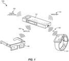
- FIG. 1 illustrates an embodiment 100 of a mobile electronic device.
- the mobile electronic device 101 may be designed to operate in conjunction with other mobile or stationary electronic devices. These electronic devices may include smartphones, smartwatches, virtual reality (VR) head-mounted displays (HMDs), augmented reality glasses, laptops, tablets, personal computers, internet of things (IoT) devices (e.g., smart doorbells, refrigerators, coffee makers), or any other electronic devices that are capable of wired or wireless communication.
- the mobile electronic device 101 may include different types of antennas to communicate on intralinks (e.g., wireless communications between local devices) or on interlinks (e.g., wireless communications between remote devices including wireless connections to the internet).
- the mobile electronic device 101 may include processors, controllers, or other processing means to perform at least some amount of distributed processing for the local devices that are connected via intralinks.
- the mobile electronic device 101 may provide processing capabilities for connected VR HMDs (e.g., 1100 of FIG. 11 ) or artificial reality devices (e.g., augmented reality glasses 1000 of FIG. 10 ) or smartwatches.
- the HMDs, glasses, or smartwatches may turn over processing tasks to the mobile electronic device 101 where those tasks will be processed.
- the mobile electronic device 101 may then return the processed results to the local devices.
- the mobile electronic device 101 may communicate with local electronic devices, perform processing for those devices, and return the results of the processing to those devices.
- the mobile electronic device 101 may connect to cellular, global navigation satellite system (GNSS), or other remote computer networks to retrieve information and pass that information to the local devices.
- GNSS global navigation satellite system
- the mobile electronic device 101 may function as a processing and/or communications hub for these local electronic devices.
- the local electronic devices may include artificial reality devices. These artificial reality devices may, themselves, include many different types of electronic hardware.
- artificial reality devices may include head-mounted displays that provide a virtual reality environment or augmented reality glasses that provide an augmented reality environment. In such cases, these HMDs may fully cover the user's eyes, and the user may be entirely enveloped in the virtual environment.
- artificial reality devices may include augmented reality glasses or other similar devices. In such cases, the augmented reality glasses may allow the user to still see the world around them, but may project virtual objects into the physical world. As such, the wearer of the augmented reality glasses may see real world objects as well as virtual objects that are projected onto the user's eyes by the augmented reality glasses.
- Smartphones, smartwatches, and other mobile electronic devices may be used in conjunction with these artificial reality devices and/or with the mobile electronic device 101.
- the mobile electronic device 101 may include many types of antennas, sensors, and other electronic components. These antennas may include WiFi antennas, Bluetooth antennas, global navigation satellite system (GNSS) or global positioning system (GPS) antennas, cellular antennas (e.g., 5G, 6G, 7G, etc.), Ultrawideband (UWB) antennas, near-field communication (NFC) antennas, or other types of antennas.
- the mobile electronic device 101 may also include microphones, speakers, batteries, cameras, printed circuit boards (PCBs), touch sensors, buttons, insulating or heat conducting materials for thermal management, simultaneous location and mapping (SLAM) sensors, or other components.
- GNSS global navigation satellite system
- GPS global positioning system
- UWB Ultrawideband
- NFC near-field communication
- the mobile electronic device 101 may also include microphones, speakers, batteries, cameras, printed circuit boards (PCBs), touch sensors, buttons, insulating or heat conducting materials for thermal management, simultaneous location and mapping (SLAM) sensors, or other components.
- the mobile electronic device 101 may be in communication with other local or remote electronic devices. As shown in FIG. 1 , the mobile electronic device 101 may communicate with many different types of devices on many different types of antennas or radios. These radios may establish intralinks and interlinks. As the terms are used herein, "intralinks" may refer to wireless communication links between local devices that are within a few hundred feet of the mobile electronic device 101. The term “interlinks” may refer to wireless communication links between remote devices that may be any distance from the mobile electronic device 101, including anywhere in the world or space (e.g., links to satellites).
- Interlinks may be established using cellular radios 102 (e.g., long term evolution (LTE), 5G, 6G, 7G, etc.), FR1 frequency radios (e.g., 617MHz-7.125GHz, see 501 of FIG. 5A), FR2 frequency radios (e.g., 24.25-52.66GHz, see 502 of FIG. 5B), GNSS radios 103, WiFi radios or other similar communications devices.
- LTE long term evolution
- 5G, 6G, 7G, etc. FR1 frequency radios
- FR2 frequency radios e.g., 24.25-52.66GHz, see 502 of FIG. 5B
- GNSS radios 103 GNSS radios or other similar communications devices.
- Intralinks may be established using WiFi or line of sight (LOS) radios (e.g., 60GHz radios) 104, Bluetooth radios 105 (e.g., to a pair of artificial reality glasses 106 or to a smartwatch 107, etc.), near-field communication (NFC) radios, or other antennas designed to operate over relatively short distances (e.g., within 1-300 feet).
- LOS line of sight
- NFC near-field communication
- the smartphone may connect locally to the mobile electronic device 101 using an intralink, and may use the mobile electronic device's interlink connections to communicate with remote devices.
- each of these wireless connections may be established using different types of radios including WiFi, Bluetooth, NFC, LOS, or other radios.
- the mobile electronic device 101 may be simultaneously communicating with multiple different local and/or remote devices using multiple different types of radios.
- the combined gain of these antennas may be limited to a specified amount (e.g., 5dBi). In such cases, the embodiments herein may alter various characteristics of the mobile electronic device and/or its antennas to reduce gain and reduce directionality.
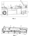
- FIG. 2 illustrates an embodiment of a mobile electronic device 201 that may be similar to or the same as mobile electronic device 101.
- the mobile electronic device 201 may include various electronic and mechanical components, including sensors such as image sensor 202 and antennas such as 204 and 206.
- the antennas 204 and 206 may be fed by antenna feeds 203 and 205, respectively.
- the antenna feeds may be electrically connected to and controlled by a main logic board 208.
- the antenna feeds may include tuners, amplifiers, impedance matching circuits, signal processors, or other feed components.
- the antennas 204 and 206 may be WiFi antennas that, in some cases, are designed to operate simultaneously at the same frequency. In such cases, the combined gain for the two antennas may approach or exceed established limits.
- the gain and directionality of these antennas may be reduced while still maintaining a minimum level of operational efficiency by removing or adding other antennas in the vicinity of these WiFi antennas, by positioning one or both of the WiFi antennas at the center of the mobile device, as opposed to placement on the edges of the device, or by implementing a parasitic element to control the radiation pattern of the WiFi antennas.
- the principles disclosed herein may apply to substantially any type of antenna operating at substantially any frequency.
- FIG. 3 illustrates an embodiment in which antenna directivity may be reduced by placing antennas closer to the center of a mobile electronic device 301.
- antenna directivity (and thus gain) may be higher when the antennas are placed near the edges of the mobile device 301.
- gain may be limited for a given antenna or group of two or more antennas.
- one or more of the device's antennas 302 may be positioned substantially in the center of the device. Because the antennas in the center are surrounded by other components that may introduce interference, the gain (and directionality) of such antennas may be reduced.
- the mobile electronic device 301 may include a chassis or frame (alternatively referred to as a "support structure" herein).
- the support structure 308 may extend substantially the full length of the mobile device.
- the center of the support structure 308 may be substantially the center of the mobile device.
- various antennas 302 may be positioned in the center of the mobile device 301. In some cases, the antennas are moved from the edges 305 of the device to the center of the device. Other antennas, such as antenna 304 may remain located on the edge of the mobile device, fed by an antenna feed affixed to the mobile device's main logic board 303 that also controls sensors (e.g., 306) or other components.
- FIG. 4A illustrates an embodiment 400 of a chart 401 that shows example test results for an edge-mounted antenna (402), for a baseline antenna (403) and for a center-mounted antenna (404).
- the edge-mounted antenna may experience the highest levels of gain and directivity, while the baseline antenna experiences less, and the center-mounted antenna experiences the least amount of gain and directivity.
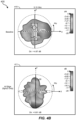
- FIG. 4B illustrates three antenna patterns for antennas operating at 5.15GHz.
- Radiation pattern 411 in the middle illustrates a radiation pattern of an edge-mounted antenna, showing a directivity of 6.61dB.
- Radiation pattern 410 on the top illustrates a radiation pattern of a baseline antenna, showing a directivity of 4.87dB, while radiation pattern 412 on the bottom shows a radiation pattern of a center-mounted antenna having a directivity of only 4.19dB.
- the center-mounted antennas experienced a lower gain and a lower directivity, which may allow the center-mounted antenna to continue operating, even in cases where EIRP or other radiated power limits place constraints on how the antennas are allowed to operate.
- FIG. 5 illustrates an embodiment of a mobile electronic device 501 that may include different electronic and mechanical components including an antenna 505, an antenna feed 509, a camera 504, and potentially other components.
- the mobile device 501 may include antennas in the center of the device, or potentially along the edges (e.g., 506).
- the directivity of an antenna in the mobile electronic device 501 may be reduced by removing other antennas around a specific antenna whose directivity is to be controlled.
- the unintended radiation of those surrounding antennas may constructively or destructively interfere with the WiFi antenna 508.
- the surrounding antennas at 502 or 503 may correspondingly increase or decrease directivity of the controlled antenna (e.g., due to reflections).
- one or more of these surrounding antennas may be added or removed from the antenna architecture of the mobile device 501. In this manner, the unintended radiation of the controlled antenna may be reduced. This, in turn, may reduce directionality in the controlled antenna and allowing the controlled antenna to operate at a higher power level if needed without exceeding applicable gain limits (e.g., EIRP limits).
- FIGS. 6A and 6B illustrate embodiments 600A and 600B showing example test data in which the directivity of an antenna that is to be controlled is compared to a baseline.
- the directivity of the antenna under control (602) is higher than that of the baseline antenna (603).
- the directivity of the antenna under control was increased by removing nearby antennas.
- radiation pattern 604 of FIG. 6B shows a higher directivity (6.61dB) at 5.15GHz than a baseline antenna (605) (4.87dB) at the same frequency.
- inventions may demonstrate a decrease in directivity, for example, by adding nearby antennas which would reshape the antenna radiation pattern, thereby changing directivity.
- FIG. 7A illustrates an embodiment of a system 700 that may include a support structure 701.
- the support structure may have a ground plane 707 that is connected to an electrical ground (708).
- the system 700 may include various antennas including antenna 704 mounted to the support structure 701.
- the system may further include a printed circuit board 703 that has an antenna feed 702 configured to drive the antenna 704.
- the system 700 may also include a parasitic ground plane extension 706.
- the parasitic ground plane extension 706 may be electrically connected to the ground plane 707 and may include various specific electrical characteristics that modify the antenna 704's radiation pattern using a designed flow of ground current.
- the parasitic ground plane extension 706 may be formed in different sizes and/or shapes, and may be positioned in specific locations on the system 700 in order to control the flow of ground current in a specified manner. Specifically, the parasitic ground plane extension 706 may be sized, shaped, positioned, or otherwise structured to direct the flow of ground current in a manner that reduces the directionality of the antenna 704 (or another antenna). In one embodiment, the parasitic ground plane extension 706 may be sized to include a larger surface area. This larger surface area may draw more of the ground current to the parasitic ground plane extension 706, thereby reshaping the radiation pattern of the antenna and ultimately changing the directivity of the antenna.
- the parasitic ground plane extension 706 may be formed in a wide or broad shape that draws more ground current to the parasitic ground plane extension 706 and, thus, may reduce the directionality of the antenna. Conversely, in other embodiments, the parasitic ground plane extension 706 may be formed into a shape that is narrower and that draws less ground current to the parasitic ground plane extension 706. Such embodiments may reduce the gain or directionality of the antenna, but to a lesser degree.
- the parasitic ground plane extension 706 may be positioned in a specific location within the support structure (e.g., near the antenna 704 or farther from the antenna, or nearer to the ground plane or farther from it, etc.). In such embodiments, for example, if the parasitic ground plane extension 706 is positioned closer to the antenna 704, the parasitic ground plane extension 706 may reduce directionality in the antenna. If the parasitic ground plane extension 706 is positioned further from the antenna 704, the parasitic ground plane extension 706 may still reduce directionality, but may do so to a lesser extent. In some cases, a specified maximum distance may be established for the parasitic ground plane extension 706 beyond which, the parasitic ground plane extension begins to lose effectiveness. In such cases, the parasitic ground plane extension 706 may be positioned within that specified maximum distance from the location of the antenna.
- the parasitic ground plane extension 706 may be grounded to the support structure 701. In other embodiments, the parasitic ground plane extension 706 may be electrically grounded to the electrical ground of the PCB 703. Alternatively, in some cases, the parasitic ground plane extension 706 may be electrically connected to both the electrical ground of the PCB 703 and to the ground plane of the support structure 701. Other grounding architectures may also be used with the parasitic ground plane extension 706. As noted above, the ground plane of the mobile device may have ground currents flowing therethrough. The parasitic ground plane extension 706 may be designed to change the flow of those currents to shape the radiation pattern of the antenna (e.g., a WiFi antenna).
- the antenna e.g., a WiFi antenna
- the parasitic ground plane extension 706 may draw more of the ground currents flowing through the ground plane. Drawing away these currents may reduce directionality in the associated antenna(s) more than would, for instance, a smaller or narrower design parasitic ground plane extension. Still further, the parasitic ground plane extension 706 may be positioned closer to or further from an antenna whose gain and/or directionality is to be controlled. The combination of size, shape, and/or position may greatly affect the degree to which the parasitic ground plane extension 706 reduces the directionality and gain of the associated antenna.
- Chart 801 of FIG. 8A illustrates a total operational efficiency for antennas with a parasitic element (e.g., 803) and without a parasitic element (e.g., 802), with the antenna implementing the parasitic element showing a total efficiency comparable to embodiments where the parasitic element was not used. This may ensure that the total radiated power remains identical for both cases.
- Chart 805 of FIG. 8B illustrates a substantial decrease in measured directivity across a range of frequencies, with the baseline antenna shown in line 806, and the antenna with parasitic element shown in line 807. Likewise, in FIG.
- chart 810 illustrates a notable decrease in gain when the antenna with parasitic element (line 812) is compared to the baseline antenna (line 811).
- the radiation patterns 815 and 816 of FIG. 8D illustrate a marked drop in directivity from 6.61dB in the baseline antenna (e.g., 815) to 4.41dB in the antenna implementing the parasitic element (e.g., 816).
- the parasitic ground plane extension element may provide measurable and notable differences over embodiments in which such an element is not used.
- FIG. 9 is a flow diagram of a method of manufacturing for providing, forming, creating, or otherwise generating a mobile device that includes one or more of the antenna architectures described herein.
- the steps shown in FIG. 9 may be performed by any suitable manufacturing equipment, including 3D printers, and may be controlled via computer-executable code and/or networked computing systems.
- each of the steps shown in FIG. 9 may represent an algorithm whose structure includes and/or is represented by multiple substeps, examples of which will be provided in greater detail below.
- the method of manufacturing 900 of FIG. 9 may include, at step 910, providing a support structure (e.g., 701 of FIG. 7 ) having a ground plane 707 that is connected to an electrical ground 708.
- the method of manufacturing 900 may also include, at step 920, mounting at least one antenna 704 to the support structure and, at step 930, providing a printed circuit board 703 including at least one antenna feed 702 configured to drive the antenna.
- the method of manufacturing 900 may include electrically connecting a parasitic ground plane extension 706 to the ground plane.
- the parasitic ground plane extension 706 may include one or more specific electrical characteristics that modify the antenna's radiation pattern using a designed flow of ground current.
- the method of manufacturing 900 may be implemented to produce a mobile electronic device.
- a mobile device may include a support structure having a ground plane that is connected to an electrical ground.
- the mobile device may also include at least one antenna that is mounted to the support structure, along with a printed circuit board that includes an antenna feed configured to drive the antenna.
- the mobile device may include a parasitic ground plane extension electrically connected to the ground plane.
- the parasitic ground plane extension may include specific electrical characteristics that modify the antenna's radiation pattern using a designed flow of ground current.
- the embodiments described herein may reduce directionality in an antenna or group of antennas by moving one or more of the antennas to the center of the device and/or by adding or removing antennas from regions surrounding the antennas under control. In this manner, the directivity of an antenna or group of antennas may be controlled to allow efficient operation while still remaining below specified gain limits.
- a system may include a support structure having a ground plane that is connected to an electrical ground, at least one antenna mounted to the support structure, a printed circuit board (PCB) including at least one antenna feed configured to drive the antenna, and a parasitic ground plane extension electrically connected to the ground plane, wherein the parasitic ground plane extension includes one or more specific electrical characteristics that modify the antenna's radiation pattern using a designed flow of ground current.
- PCB printed circuit board
- Example 2 The system of Example 1, wherein the designed flow of ground current is structured to direct the flow of ground current in a manner that reduces directionality of the antenna.
- Example 3 The system of Example 1 or Example 2, wherein the parasitic ground plane extension is formed in a size that reduces directionality in the antenna.
- Example 4 The system of any of Examples 1-3, wherein the parasitic ground plane extension is formed in a shape that reduces directionality in the antenna.
- Example 5 The system of any of Examples 1-4, wherein the parasitic ground plane extension is positioned in a specific location within the support structure, such that the position of the parasitic ground plane extension reduces directionality in the antenna.
- Example 6 The system of any of Examples 1-5, wherein the position of the parasitic ground plane extension within the support structure is within a specified maximum distance from the location of the antenna.
- Example 7 The system of any of Examples 1-6, wherein the parasitic ground plane extension is grounded to the support structure.
- Example 8 The system of any of Examples 1-7, wherein one or more different antennas within a specified minimum distance of the parasitic ground plane extension are removed from the system.
- Example 9 The system of any of Examples 1-8, wherein one or more different antennas are added to the system within a specified maximum distance from the parasitic ground plane extension.
- Example 10 The system of any of Examples 1-9, wherein the antenna is positioned substantially in the center of the support structure.
- Example 11 The system of any of Examples 1-10, wherein the PCB has an electrical ground, and wherein the parasitic ground plane extension is electrically connected to the electrical ground of the PCB.
- Example 12 The system of any of Examples 1-11, wherein the parasitic ground plane extension is electrically connected to the electrical ground of the PCB and to the ground plane of the support structure.
- a mobile electronic device may include: a support structure having a ground plane that is connected to an electrical ground, at least one antenna mounted to the support structure, a printed circuit board (PCB) including at least one antenna feed configured to drive the antenna, and a parasitic ground plane extension electrically connected to the ground plane, wherein the parasitic ground plane extension includes one or more specific electrical characteristics that modify the antenna's radiation pattern using a designed flow of ground current.
- PCB printed circuit board
- Example 14 The mobile electronic device of Example 13, wherein the designed flow of ground current is structured to direct the flow of ground current in a manner that reduces directionality of the antenna.
- Example 15 The mobile electronic device of Example 13 or Example 14, wherein the parasitic ground plane extension is formed in a size that reduces directionality in the antenna, and wherein the size of the parasitic ground plane extension depends on an amount of conductive material surrounding the antenna.
- Example 16 The mobile electronic device of any of Examples 13-15, wherein the parasitic ground plane extension is formed in a shape that reduces directionality in the antenna, and wherein the shape of the parasitic ground plane extension depends on an amount of conductive material surrounding the antenna.
- Example 17 The mobile electronic device of any of Examples 13-16, wherein the parasitic ground plane extension is positioned in a specific location within the support structure, such that the position of the parasitic ground plane extension reduces directionality in the antenna.
- Example 18 The mobile electronic device of any of Examples 13-17, wherein the PCB has an electrical ground, and wherein the parasitic ground plane extension is electrically connected to the electrical ground of the PCB.
- Example 19 The mobile electronic device of any of Examples 13-18, wherein the parasitic ground plane extension is electrically connected to the electrical ground of the PCB and to the ground plane of the support structure.
- a method of manufacturing may include providing a support structure having a ground plane that is connected to an electrical ground, mounting at least one antenna to the support structure, providing a printed circuit board (PCB) including at least one antenna feed configured to drive the antenna, and electrically connecting a parasitic ground plane extension to the ground plane, wherein the parasitic ground plane extension includes one or more specific electrical characteristics that modify the antenna's radiation pattern using a designed flow of ground current.
- PCB printed circuit board
- Embodiments of the present disclosure may include or be implemented in conjunction with various types of artificial-reality systems.
- Artificial reality is a form of reality that has been adjusted in some manner before presentation to a user, which may include, for example, a virtual reality, an augmented reality, a mixed reality, a hybrid reality, or some combination and/or derivative thereof.
- Artificial-reality content may include completely computer-generated content or computer-generated content combined with captured (e.g., real-world) content.
- the artificial-reality content may include video, audio, haptic feedback, or some combination thereof, any of which may be presented in a single channel or in multiple channels (such as stereo video that produces a three-dimensional (3D) effect to the viewer).
- artificial reality may also be associated with applications, products, accessories, services, or some combination thereof, that are used to, for example, create content in an artificial reality and/or are otherwise used in (e.g., to perform activities in) an artificial reality.
- Artificial-reality systems may be implemented in a variety of different form factors and configurations. Some artificial-reality systems may be designed to work without near-eye displays (NEDs). Other artificial-reality systems may include an NED that also provides visibility into the real world (such as, e.g., augmented-reality system 1000 in FIG. 10 ) or that visually immerses a user in an artificial reality (such as, e.g., virtual-reality system 1100 in FIG. 11 ). While some artificial-reality devices may be self-contained systems, other artificial-reality devices may communicate and/or coordinate with external devices to provide an artificial-reality experience to a user. Examples of such external devices include handheld controllers, mobile devices, desktop computers, devices worn by a user, devices worn by one or more other users, and/or any other suitable external system.
- augmented-reality system 1000 may include an eyewear device 1002 with a frame 1010 configured to hold a left display device 1015(A) and a right display device 1015(B) in front of a user's eyes.
- Display devices 1015(A) and 1015(B) may act together or independently to present an image or series of images to a user.
- augmented-reality system 1000 includes two displays, embodiments of this disclosure may be implemented in augmented-reality systems with a single NED or more than two NEDs.
- augmented-reality system 1000 may include one or more sensors, such as sensor 1040.
- Sensor 1040 may generate measurement signals in response to motion of augmented-reality system 1000 and may be located on substantially any portion of frame 1010.
- Sensor 1040 may represent one or more of a variety of different sensing mechanisms, such as a position sensor, an inertial measurement unit (IMU), a depth camera assembly, a structured light emitter and/or detector, or any combination thereof.
- augmented-reality system 1000 may or may not include sensor 1040 or may include more than one sensor.
- the IMU may generate calibration data based on measurement signals from sensor 1040.
- Examples of sensor 1040 may include, without limitation, accelerometers, gyroscopes, magnetometers, other suitable types of sensors that detect motion, sensors used for error correction of the IMU, or some combination thereof.
- augmented-reality system 1000 may also include a microphone array with a plurality of acoustic transducers 1020(A)-1020(J), referred to collectively as acoustic transducers 1020.
- Acoustic transducers 1020 may represent transducers that detect air pressure variations induced by sound waves.
- Each acoustic transducer 1020 may be configured to detect sound and convert the detected sound into an electronic format (e.g., an analog or digital format).
- 10 may include, for example, ten acoustic transducers: 1020(A) and 1020(B), which may be designed to be placed inside a corresponding ear of the user, acoustic transducers 1020(C), 1020(D), 1020(E), 1020(F), 1020(G), and 1020(H), which may be positioned at various locations on frame 1010, and/or acoustic transducers 1020(I) and 1020(J), which may be positioned on a corresponding neckband 1005.
- ten acoustic transducers 1020(A) and 1020(B), which may be designed to be placed inside a corresponding ear of the user
- acoustic transducers 1020(C), 1020(D), 1020(E), 1020(F), 1020(G), and 1020(H) which may be positioned at various locations on frame 1010
- acoustic transducers 1020(I) and 1020(J) which may be positioned
- acoustic transducers 1020(A)-(J) may be used as output transducers (e.g., speakers).
- acoustic transducers 1020(A) and/or 1020(B) may be earbuds or any other suitable type of headphone or speaker.
- the configuration of acoustic transducers 1020 of the microphone array may vary. While augmented-reality system 1000 is shown in FIG. 10 as having ten acoustic transducers 1020, the number of acoustic transducers 1020 may be greater or less than ten. In some embodiments, using higher numbers of acoustic transducers 1020 may increase the amount of audio information collected and/or the sensitivity and accuracy of the audio information. In contrast, using a lower number of acoustic transducers 1020 may decrease the computing power required by an associated controller 1050 to process the collected audio information. In addition, the position of each acoustic transducer 1020 of the microphone array may vary. For example, the position of an acoustic transducer 1020 may include a defined position on the user, a defined coordinate on frame 1010, an orientation associated with each acoustic transducer 1020, or some combination thereof.
- Acoustic transducers 1020(A) and 1020(B) may be positioned on different parts of the user's ear, such as behind the pinna, behind the tragus, and/or within the auricle or fossa. Or, there may be additional acoustic transducers 1020 on or surrounding the ear in addition to acoustic transducers 1020 inside the ear canal. Having an acoustic transducer 1020 positioned next to an ear canal of a user may enable the microphone array to collect information on how sounds arrive at the ear canal.
- augmented-reality system 1000 may simulate binaural hearing and capture a 3D stereo sound field around about a user's head.
- acoustic transducers 1020(A) and 1020(B) may be connected to augmented-reality system 1000 via a wired connection 1030, and in other embodiments acoustic transducers 1020(A) and 1020(B) may be connected to augmented-reality system 1000 via a wireless connection (e.g., a BLUETOOTH connection).
- acoustic transducers 1020(A) and 1020(B) may not be used at all in conjunction with augmented-reality system 1000.
- Acoustic transducers 1020 on frame 1010 may be positioned in a variety of different ways, including along the length of the temples, across the bridge, above or below display devices 1015(A) and 1015(B), or some combination thereof. Acoustic transducers 1020 may also be oriented such that the microphone array is able to detect sounds in a wide range of directions surrounding the user wearing the augmented-reality system 1000. In some embodiments, an optimization process may be performed during manufacturing of augmented-reality system 1000 to determine relative positioning of each acoustic transducer 1020 in the microphone array.
- augmented-reality system 1000 may include or be connected to an external device (e.g., a paired device), such as neckband 1005.
- an external device e.g., a paired device
- Neckband 1005 generally represents any type or form of paired device.
- the following discussion of neckband 1005 may also apply to various other paired devices, such as charging cases, smart watches, smart phones, wrist bands, other wearable devices, hand-held controllers, tablet computers, laptop computers, other external compute devices, etc.
- neckband 1005 may be coupled to eyewear device 1002 via one or more connectors.
- the connectors may be wired or wireless and may include electrical and/or non-electrical (e.g., structural) components.
- eyewear device 1002 and neckband 1005 may operate independently without any wired or wireless connection between them.
- FIG. 10 illustrates the components of eyewear device 1002 and neckband 1005 in example locations on eyewear device 1002 and neckband 1005, the components may be located elsewhere and/or distributed differently on eyewear device 1002 and/or neckband 1005.
- the components of eyewear device 1002 and neckband 1005 may be located on one or more additional peripheral devices paired with eyewear device 1002, neckband 1005, or some combination thereof.
- Pairing external devices such as neckband 1005
- augmented-reality eyewear devices may enable the eyewear devices to achieve the form factor of a pair of glasses while still providing sufficient battery and computation power for expanded capabilities.
- Some or all of the battery power, computational resources, and/or additional features of augmented-reality system 1000 may be provided by a paired device or shared between a paired device and an eyewear device, thus reducing the weight, heat profile, and form factor of the eyewear device overall while still retaining desired functionality.
- neckband 1005 may allow components that would otherwise be included on an eyewear device to be included in neckband 1005 since users may tolerate a heavier weight load on their shoulders than they would tolerate on their heads.
- Neckband 1005 may also have a larger surface area over which to diffuse and disperse heat to the ambient environment. Thus, neckband 1005 may allow for greater battery and computation capacity than might otherwise have been possible on a stand-alone eyewear device. Since weight carried in neckband 1005 may be less invasive to a user than weight carried in eyewear device 1002, a user may tolerate wearing a lighter eyewear device and carrying or wearing the paired device for greater lengths of time than a user would tolerate wearing a heavy standalone eyewear device, thereby enabling users to more fully incorporate artificial-reality environments into their day-to-day activities.
- Neckband 1005 may be communicatively coupled with eyewear device 1002 and/or to other devices. These other devices may provide certain functions (e.g., tracking, localizing, depth mapping, processing, storage, etc.) to augmented-reality system 1000.
- neckband 1005 may include two acoustic transducers (e.g., 1020(I) and 1020(J)) that are part of the microphone array (or potentially form their own microphone subarray).
- Neckband 1005 may also include a controller 1025 and a power source 1035.
- Acoustic transducers 1020(I) and 1020(J) of neckband 1005 may be configured to detect sound and convert the detected sound into an electronic format (analog or digital).
- acoustic transducers 1020(I) and 1020(J) may be positioned on neckband 1005, thereby increasing the distance between the neckband acoustic transducers 1020(I) and 1020(J) and other acoustic transducers 1020 positioned on eyewear device 1002.
- increasing the distance between acoustic transducers 1020 of the microphone array may improve the accuracy of beamforming performed via the microphone array.
- the determined source location of the detected sound may be more accurate than if the sound had been detected by acoustic transducers 1020(D) and 1020(E).
- Controller 1025 of neckband 1005 may process information generated by the sensors on neckband 1005 and/or augmented-reality system 1000.
- controller 1025 may process information from the microphone array that describes sounds detected by the microphone array. For each detected sound, controller 1025 may perform a direction-of-arrival (DOA) estimation to estimate a direction from which the detected sound arrived at the microphone array. As the microphone array detects sounds, controller 1025 may populate an audio data set with the information.
- controller 1025 may compute all inertial and spatial calculations from the IMU located on eyewear device 1002.
- a connector may convey information between augmented-reality system 1000 and neckband 1005 and between augmented-reality system 1000 and controller 1025. The information may be in the form of optical data, electrical data, wireless data, or any other transmittable data form. Moving the processing of information generated by augmented-reality system 1000 to neckband 1005 may reduce weight and heat in eyewear device 1002, making it more comfortable to the user.
- Power source 1035 in neckband 1005 may provide power to eyewear device 1002 and/or to neckband 1005.
- Power source 1035 may include, without limitation, lithium-ion batteries, lithium-polymer batteries, primary lithium batteries, alkaline batteries, or any other form of power storage.
- power source 1035 may be a wired power source. Including power source 1035 on neckband 1005 instead of on eyewear device 1002 may help better distribute the weight and heat generated by power source 1035.
- some artificial-reality systems may, instead of blending an artificial reality with actual reality, substantially replace one or more of a user's sensory perceptions of the real world with a virtual experience.
- a head-worn display system such as virtual-reality system 1100 in FIG. 11 , that mostly or completely covers a user's field of view.
- Virtual-reality system 1100 may include a front rigid body 1102 and a band 1104 shaped to fit around a user's head.
- Virtual-reality system 1100 may also include output audio transducers 1106(A) and 1106(B).
- FIG. 11 a head-worn display system
- front rigid body 1102 may include one or more electronic elements, including one or more electronic displays, one or more inertial measurement units (IMUs), one or more tracking emitters or detectors, and/or any other suitable device or system for creating an artificial-reality experience.
- IMUs inertial measurement units
- tracking emitters or detectors and/or any other suitable device or system for creating an artificial-reality experience.
- Artificial-reality systems may include a variety of types of visual feedback mechanisms.
- display devices in augmented-reality system 1000 and/or virtual-reality system 1100 may include one or more liquid crystal displays (LCDs), light emitting diode (LED) displays, microLED displays, organic LED (OLED) displays, digital light project (DLP) micro-displays, liquid crystal on silicon (LCoS) micro-displays, and/or any other suitable type of display screen.
- LCDs liquid crystal displays
- LED light emitting diode
- microLED organic LED
- DLP digital light project
- LCD liquid crystal on silicon
- These artificial-reality systems may include a single display screen for both eyes or may provide a display screen for each eye, which may allow for additional flexibility for varifocal adjustments or for correcting a user's refractive error.
- Some of these artificial-reality systems may also include optical subsystems having one or more lenses (e.g., concave or convex lenses, Fresnel lenses, adjustable liquid lenses, etc.) through which a user may view a display screen.
- optical subsystems may serve a variety of purposes, including to collimate (e.g., make an object appear at a greater distance than its physical distance), to magnify (e.g., make an object appear larger than its actual size), and/or to relay (to, e.g., the viewer's eyes) light.
- optical subsystems may be used in a non-pupil-forming architecture (such as a single lens configuration that directly collimates light but results in so-called pincushion distortion) and/or a pupil-forming architecture (such as a multi-lens configuration that produces so-called barrel distortion to nullify pincushion distortion).
- a non-pupil-forming architecture such as a single lens configuration that directly collimates light but results in so-called pincushion distortion
- a pupil-forming architecture such as a multi-lens configuration that produces so-called barrel distortion to nullify pincushion distortion
- some of the artificial-reality systems described herein may include one or more projection systems.
- display devices in augmented-reality system 1000 and/or virtual-reality system 1100 may include microLED projectors that project light (using, e.g., a waveguide) into display devices, such as clear combiner lenses that allow ambient light to pass through.
- the display devices may refract the projected light toward a user's pupil and may enable a user to simultaneously view both artificial-reality content and the real world.
- the display devices may accomplish this using any of a variety of different optical components, including waveguide components (e.g., holographic, planar, diffractive, polarized, and/or reflective waveguide elements), light-manipulation surfaces and elements (such as diffractive, reflective, and refractive elements and gratings), coupling elements, etc.
- waveguide components e.g., holographic, planar, diffractive, polarized, and/or reflective waveguide elements
- light-manipulation surfaces and elements such as diffractive, reflective, and refractive elements and gratings
- coupling elements etc.
- Artificial-reality systems may also be configured with any other suitable type or form of image projection system, such as retinal projectors used in virtual retina displays.
- augmented-reality system 1000 and/or virtual-reality system 1100 may include one or more optical sensors, such as two-dimensional (2D) or 3D cameras, structured light transmitters and detectors, time-of-flight depth sensors, single-beam or sweeping laser rangefinders, 3D LiDAR sensors, and/or any other suitable type or form of optical sensor.
- An artificial-reality system may process data from one or more of these sensors to identify a location of a user, to map the real world, to provide a user with context about real-world surroundings, and/or to perform a variety of other functions.
- the artificial-reality systems described herein may also include one or more input and/or output audio transducers.
- Output audio transducers may include voice coil speakers, ribbon speakers, electrostatic speakers, piezoelectric speakers, bone conduction transducers, cartilage conduction transducers, tragus-vibration transducers, and/or any other suitable type or form of audio transducer.
- input audio transducers may include condenser microphones, dynamic microphones, ribbon microphones, and/or any other type or form of input transducer.
- a single transducer may be used for both audio input and audio output.
- the artificial-reality systems described herein may also include tactile (i.e., haptic) feedback systems, which may be incorporated into headwear, gloves, body suits, handheld controllers, environmental devices (e.g., chairs, floormats, etc.), and/or any other type of device or system.
- Haptic feedback systems may provide various types of cutaneous feedback, including vibration, force, traction, texture, and/or temperature.
- Haptic feedback systems may also provide various types of kinesthetic feedback, such as motion and compliance.
- Haptic feedback may be implemented using motors, piezoelectric actuators, fluidic systems, and/or a variety of other types of feedback mechanisms.
- Haptic feedback systems may be implemented independent of other artificial-reality devices, within other artificial-reality devices, and/or in conjunction with other artificial-reality devices.
- artificial-reality systems may create an entire virtual experience or enhance a user's real-world experience in a variety of contexts and environments. For instance, artificial-reality systems may assist or extend a user's perception, memory, or cognition within a particular environment. Some systems may enhance a user's interactions with other people in the real world or may enable more immersive interactions with other people in a virtual world.
- Artificial-reality systems may also be used for educational purposes (e.g., for teaching or training in schools, hospitals, government organizations, military organizations, business enterprises, etc.), entertainment purposes (e.g., for playing video games, listening to music, watching video content, etc.), and/or for accessibility purposes (e.g., as hearing aids, visual aids, etc.).
- the embodiments disclosed herein may enable or enhance a user's artificial-reality experience in one or more of these contexts and environments and/or in other contexts and environments.
- computing devices and systems described and/or illustrated herein broadly represent any type or form of computing device or system capable of executing computer-readable instructions, such as those contained within the modules described herein.
- these computing device(s) may each include at least one memory device and at least one physical processor.
- the term "memory device” generally refers to any type or form of volatile or non-volatile storage device or medium capable of storing data and/or computer-readable instructions.
- a memory device may store, load, and/or maintain one or more of the modules described herein.
- Examples of memory devices include, without limitation, Random Access Memory (RAM), Read Only Memory (ROM), flash memory, Hard Disk Drives (HDDs), Solid-State Drives (SSDs), optical disk drives, caches, variations or combinations of one or more of the same, or any other suitable storage memory.
- the term "physical processor” generally refers to any type or form of hardware-implemented processing unit capable of interpreting and/or executing computer-readable instructions.
- a physical processor may access and/or modify one or more modules stored in the above-described memory device.
- Examples of physical processors include, without limitation, microprocessors, microcontrollers, Central Processing Units (CPUs), Field-Programmable Gate Arrays (FPGAs) that implement softcore processors, Application-Specific Integrated Circuits (ASICs), portions of one or more of the same, variations or combinations of one or more of the same, or any other suitable physical processor.
- modules described and/or illustrated herein may represent portions of a single module or application.
- one or more of these modules may represent one or more software applications or programs that, when executed by a computing device, may cause the computing device to perform one or more tasks.
- one or more of the modules described and/or illustrated herein may represent modules stored and configured to run on one or more of the computing devices or systems described and/or illustrated herein.
- One or more of these modules may also represent all or portions of one or more special-purpose computers configured to perform one or more tasks.
- one or more of the modules described herein may transform data, physical devices, and/or representations of physical devices from one form to another. Additionally or alternatively, one or more of the modules recited herein may transform a processor, volatile memory, non-volatile memory, and/or any other portion of a physical computing device from one form to another by executing on the computing device, storing data on the computing device, and/or otherwise interacting with the computing device.
- the term "computer-readable medium” generally refers to any form of device, carrier, or medium capable of storing or carrying computer-readable instructions.
- Examples of computer-readable media include, without limitation, transmission-type media, such as carrier waves, and non-transitory-type media, such as magnetic-storage media (e.g., hard disk drives, tape drives, and floppy disks), optical-storage media (e.g., Compact Disks (CDs), Digital Video Disks (DVDs), and BLU-RAY disks), electronic-storage media (e.g., solid-state drives and flash media), and other distribution systems.
- transmission-type media such as carrier waves
- non-transitory-type media such as magnetic-storage media (e.g., hard disk drives, tape drives, and floppy disks), optical-storage media (e.g., Compact Disks (CDs), Digital Video Disks (DVDs), and BLU-RAY disks), electronic-storage media (e.g., solid-state drives
Landscapes
- Support Of Aerials (AREA)
Abstract
Description
- This application claims priority to
U.S. Provisional Application No. 63/376,730, filed September 22, 2022 - The present disclosure is generally directed to methods and systems for controlling an antenna's radiation pattern.
- The radiation pattern of an antenna may be controlled by adding or removing other antennas from the vicinity of specific antennas, by optimizing the position of specific antennas within a mobile device, or using a parasitic ground plane extension to improve the omnidirectionality of the antenna's radiation pattern. Modern mobile electronic devices often include grounded outer enclosures as well as printed circuit boards (PCBs) with their own grounding systems. Such grounding systems (or "ground planes") may provide an electrical return path for multiple different electronic components including antennas.
- During operation, these antennas may be limited in how much power density they can radiate into the surrounding environment in a given direction. For instance, some governmental regulations may limit the amount of gain for antennas on a mobile electronic device to 5 dBi. In some cases, adhering to these limits may be achieved by reducing the antenna's operating power and/or reducing the antenna's efficiency. This, however, may lead to a reduction in total radiated power by the antenna, and may ultimately degrade the antenna link's quality.
- In accordance with the invention in a first aspect, a system comprises:
- a support structure comprising a ground plane that is connected to an electrical ground;
- at least one antenna mounted to the support structure;
- a printed circuit board (PCB) including at least one antenna feed configured to drive the antenna; and
- a parasitic ground plane extension electrically connected to the ground plane, wherein the parasitic ground plane extension includes one or more specific electrical characteristics that modify the antenna's radiation pattern using a designed flow of ground current.
- In some embodiments, the designed flow of ground current is structured to direct the flow of ground current in a manner that reduces directionality of the antenna.
- In some embodiments, the parasitic ground plane extension is formed in a size that reduces directionality in the antenna.
- In some embodiments, the parasitic ground plane extension is formed in a shape that reduces directionality in the antenna.
- In some embodiments, the parasitic ground plane extension is positioned in a specific location within the support structure, such that the position of the parasitic ground plane extension reduces directionality in the antenna.
- In some embodiments, the position of the parasitic ground plane extension within the support structure is within a specified maximum distance from the location of the antenna.
- In some embodiments, the parasitic ground plane extension is grounded to the support structure.
- In some embodiments, one or more different antennas within a specified minimum distance of the parasitic ground plane extension are removed from the system.
- In some embodiments, one or more different antennas are added to the system within a specified maximum distance from the parasitic ground plane extension.
- In some embodiments, the antenna is positioned substantially in the center of the support structure.
- In some embodiments, the PCB has an electrical ground, and the parasitic ground plane extension is electrically connected to the electrical ground of the PCB.
- In some embodiments, the parasitic ground plane extension is electrically connected to the electrical ground of the PCB and to the ground plane of the support structure.
- In accordance with the invention in a second aspect, a mobile electronic device comprises:
- a support structure comprising a ground plane that is connected to an electrical ground;
- at least one antenna mounted to the support structure;
- a printed circuit board (PCB) including at least one antenna feed configured to drive the antenna; and
- a parasitic ground plane extension electrically connected to the ground plane, wherein the parasitic ground plane extension includes one or more specific electrical characteristics that modify the antenna's radiation pattern using a designed flow of ground current.
- For example, the mobile electronic device of the second aspect comprises a system of the first aspect, and preferred features will be understood to apply interchangeably between the two aspects where technically feasible.
- In some embodiments, the designed flow of ground current is structured to direct the flow of ground current in a manner that reduces directionality of the antenna.
- In some embodiments, the parasitic ground plane extension is formed in a size that reduces directionality in the antenna, and wherein the size of the parasitic ground plane extension depends on an amount of conductive material surrounding the antenna.
- In some embodiments, the parasitic ground plane extension is formed in a shape that reduces directionality in the antenna, and wherein the shape of the parasitic ground plane extension depends on an amount of conductive material surrounding the antenna.
- In some embodiments, the parasitic ground plane extension is positioned in a specific location within the support structure, such that the position of the parasitic ground plane extension reduces directionality in the antenna.
- In some embodiments, the PCB has an electrical ground, and the parasitic ground plane extension is electrically connected to the electrical ground of the PCB.
- In some embodiments, the parasitic ground plane extension is electrically connected to the electrical ground of the PCB and to the ground plane of the support structure.
- In accordance with the invention in a third aspect, a method of manufacturing comprises:
- providing a support structure comprising a ground plane that is connected to an electrical ground;
- mounting at least one antenna to the support structure;
- providing a printed circuit board (PCB) including at least one antenna feed configured to drive the antenna; and
- electrically connecting a parasitic ground plane extension to the ground plane, wherein the parasitic ground plane extension includes one or more specific electrical characteristics that modify the antenna's radiation pattern using a designed flow of ground current.
- Features of possible embodiments of the third aspect of the invention will be understood by analogy with discussion of other aspects.
- The accompanying drawings illustrate a number of exemplary embodiments and are a part of the specification. Together with the following description, these drawings demonstrate and explain various principles of the present disclosure.
-
FIG. 1 illustrates an embodiment of a mobile electronic device establishing and implementing different communication links between the mobile electronic device and other electronic devices. -
FIG. 2 illustrates an embodiment of a portion of the mobile electronic device that includes at least two different antennas. -
FIG. 3 illustrates an embodiment in which antennas are positioned in the center of the mobile electronic device to reduce gain. -
FIGS. 4A-4B illustrate directivity charts and radiation patterns for specific antennas. -
FIG. 5 illustrates an embodiment in which one or more antennas are added to or removed from an area near a specific type of antenna. -
FIGS. 6A-6B illustrate directivity charts and radiation patterns for specific antennas. -
FIGS. 7A-7B illustrate embodiments in which a parasitic ground plane extension is implemented on a mobile electronic device. -
FIGS. 8A-8D illustrate efficiency, directivity, and gain charts, as well as radiation patterns for a specific type of antenna. -
FIG. 9 is a flow diagram of an exemplary method for manufacturing a mobile electronic device that includes one or more of the antenna architectures described herein. -
FIG. 10 is an illustration of exemplary augmented-reality glasses that may be used in connection with embodiments of this disclosure. -
FIG. 11 is an illustration of an exemplary virtual-reality headset that may be used in connection with embodiments of this disclosure. - Throughout the drawings, identical reference characters and descriptions indicate similar, but not necessarily identical, elements. While the exemplary embodiments described herein are susceptible to various modifications and alternative forms, specific embodiments have been shown by way of example in the drawings and will be described in detail herein. However, the exemplary embodiments described herein are not intended to be limited to the particular forms disclosed. Rather, the present disclosure covers all modifications, equivalents, and alternatives falling within the scope of the appended claims.
- The present disclosure is generally directed to methods and systems for controlling an antenna's radiation pattern. The antenna's radiation pattern may be controlled by adding or removing other antennas from the vicinity of specific antennas, by optimizing the position of specific antennas within a mobile device, or using a parasitic ground plane extension to improve the omnidirectionality of the antenna's radiation pattern. Modern mobile electronic devices often include grounded outer enclosures as well as printed circuit boards (PCBs) with their own grounding systems. Such grounding systems (or "ground planes") may provide an electrical return path for multiple different electronic components including antennas.
- During operation, these antennas may be limited in how much power density they can radiate into the surrounding environment in a given direction. For instance, some governmental regulations may limit the amount of gain for antennas on a mobile electronic device to 5 dBi. In some cases, adhering to these limits may be achieved by reducing the antenna's operating power and/or reducing the antenna's efficiency. This, however, may lead to a reduction in total radiated power by the antenna, and may ultimately degrade the antenna link's quality.
- The embodiments described herein may be configured to retain total radiated power by the mobile device antennas while reducing the directionality of the antenna. Indeed, due to their design, some antennas may radiate electromagnetic waves in a more directional manner or in a more omnidirectional manner. If the antennas are overly directional, they may surpass the gain limit (e.g., 5 dBi) more easily than antennas that are more omnidirectional. This issue may be compounded by the fact that a mobile device may have multiple such antennas radiating in tandem. Accordingly, at least some of the embodiments described herein may implement a parasitic ground plane extension to modify and shape the radiation patterns of one or more antennas on a given mobile device to reduce that antenna's directivity. By reducing the antennas' directivity, the embodiments herein may cause the antennas described herein to be more omnidirectional and may thereby ensure that the gain limit is not exceeded in any given direction.
- As will be described further below, antenna directivity may be reduced in multiple different ways. For instance, in some cases, the directivity of an antenna in a mobile device may be reduced by removing other antennas around a specific antenna whose directivity is to be controlled. For example, if other antennas are present near the antenna that is to be controlled (e.g., a WiFi antenna), the unintended radiation of those surrounding antennas may constructively or destructively interfere and may correspondingly increase or decrease directivity of the controlled antenna (e.g., due to reflections). When one or more of these surrounding antennas is added or removed, the unintended radiation of the controlled antenna may be lowered, thereby reducing directionality in the controlled antenna and allowing the controlled antenna to operate at a higher power level if needed without exceeding the gain limit.
- Additionally or alternatively, antenna directivity may be reduced by placing the antennas closer to the center of the mobile electronic device, as opposed to placing the antennas near the edges. In at least some embodiments, the center (or substantially near the center) of the mobile device may provide lower directivity (and thus gain) than the edges of the device. This may ensure that the antenna or any combination of antennas (e.g., WiFi, Bluetooth, global positioning system (GPS), cellular, ultrawideband (UWB) or other antennas) stays below the effective isotropic radiated power (EIRP) or other specified radiation limit. In some cases, the antenna or group of antennas may be moved to different positions at or near the center of the mobile device to provide an optimal amount of gain for each specific antenna.
- Still further, the embodiments herein may reduce directivity in antennas by adding a parasitic ground plane extension to control the antennas' radiation pattern. The parasitic ground plane extension may be a separate mechanical component that is affixed to or is incorporated into the mobile electronic device. The parasitic ground plane extension may be designed to modify or shape the directionality of different antennas' radiation patterns. In some cases, a single parasitic ground plane extension may be used, while in other cases, multiple parasitic ground plane extensions may be used in the same device. In some cases, the parasitic ground plane extension may be grounded to at least one part of the mobile device's frame or support structure. By controlling the directivity of each antenna, the embodiments herein may allow for a higher radiated power while maintaining EIRP or other specifications.
- In some cases, the size, shape, and/or placement of the parasitic ground plane extension may be specifically designed to control the shape of the radiation pattern by controlling the flow of ground currents near the antenna. This may ensure that the radiation pattern is more omnidirectional in nature and that, in any given direction, the gain limit is not exceeded. These embodiments will be described further below with regard to
FIGS. 1-11 . - Features from any of the embodiments described herein may be used in combination with one another in accordance with the general principles described herein. These and other embodiments, features, and advantages will be more fully understood upon reading the following detailed description in conjunction with the accompanying drawings and claims.
-
FIG. 1 illustrates anembodiment 100 of a mobile electronic device. The mobileelectronic device 101 may be designed to operate in conjunction with other mobile or stationary electronic devices. These electronic devices may include smartphones, smartwatches, virtual reality (VR) head-mounted displays (HMDs), augmented reality glasses, laptops, tablets, personal computers, internet of things (IoT) devices (e.g., smart doorbells, refrigerators, coffee makers), or any other electronic devices that are capable of wired or wireless communication. The mobileelectronic device 101 may include different types of antennas to communicate on intralinks (e.g., wireless communications between local devices) or on interlinks (e.g., wireless communications between remote devices including wireless connections to the internet). In some cases, the mobileelectronic device 101 may include processors, controllers, or other processing means to perform at least some amount of distributed processing for the local devices that are connected via intralinks. - For example, the mobile
electronic device 101 may provide processing capabilities for connected VR HMDs (e.g., 1100 ofFIG. 11 ) or artificial reality devices (e.g.,augmented reality glasses 1000 ofFIG. 10 ) or smartwatches. In such cases, the HMDs, glasses, or smartwatches may turn over processing tasks to the mobileelectronic device 101 where those tasks will be processed. Upon completion of the tasks, the mobileelectronic device 101 may then return the processed results to the local devices. In this manner, the mobileelectronic device 101 may communicate with local electronic devices, perform processing for those devices, and return the results of the processing to those devices. Moreover, the mobileelectronic device 101 may connect to cellular, global navigation satellite system (GNSS), or other remote computer networks to retrieve information and pass that information to the local devices. In this manner, the mobileelectronic device 101 may function as a processing and/or communications hub for these local electronic devices. - In some cases, the local electronic devices may include artificial reality devices. These artificial reality devices may, themselves, include many different types of electronic hardware. In some cases, for example, artificial reality devices may include head-mounted displays that provide a virtual reality environment or augmented reality glasses that provide an augmented reality environment. In such cases, these HMDs may fully cover the user's eyes, and the user may be entirely enveloped in the virtual environment. In other cases, artificial reality devices may include augmented reality glasses or other similar devices. In such cases, the augmented reality glasses may allow the user to still see the world around them, but may project virtual objects into the physical world. As such, the wearer of the augmented reality glasses may see real world objects as well as virtual objects that are projected onto the user's eyes by the augmented reality glasses. Smartphones, smartwatches, and other mobile electronic devices may be used in conjunction with these artificial reality devices and/or with the mobile
electronic device 101. - As noted above, the mobile
electronic device 101 may include many types of antennas, sensors, and other electronic components. These antennas may include WiFi antennas, Bluetooth antennas, global navigation satellite system (GNSS) or global positioning system (GPS) antennas, cellular antennas (e.g., 5G, 6G, 7G, etc.), Ultrawideband (UWB) antennas, near-field communication (NFC) antennas, or other types of antennas. The mobileelectronic device 101 may also include microphones, speakers, batteries, cameras, printed circuit boards (PCBs), touch sensors, buttons, insulating or heat conducting materials for thermal management, simultaneous location and mapping (SLAM) sensors, or other components. - In
embodiment 100 ofFIG. 1 , the mobileelectronic device 101 may be in communication with other local or remote electronic devices. As shown inFIG. 1 , the mobileelectronic device 101 may communicate with many different types of devices on many different types of antennas or radios. These radios may establish intralinks and interlinks. As the terms are used herein, "intralinks" may refer to wireless communication links between local devices that are within a few hundred feet of the mobileelectronic device 101. The term "interlinks" may refer to wireless communication links between remote devices that may be any distance from the mobileelectronic device 101, including anywhere in the world or space (e.g., links to satellites). - Interlinks may be established using cellular radios 102 (e.g., long term evolution (LTE), 5G, 6G, 7G, etc.), FR1 frequency radios (e.g., 617MHz-7.125GHz, see 501 of FIG. 5A), FR2 frequency radios (e.g., 24.25-52.66GHz, see 502 of FIG. 5B),
GNSS radios 103, WiFi radios or other similar communications devices. Intralinks may be established using WiFi or line of sight (LOS) radios (e.g., 60GHz radios) 104, Bluetooth radios 105 (e.g., to a pair ofartificial reality glasses 106 or to asmartwatch 107, etc.), near-field communication (NFC) radios, or other antennas designed to operate over relatively short distances (e.g., within 1-300 feet). - In some embodiments, for instance, if the smartphone is incapable of making a cellular connection, the smartphone may connect locally to the mobile
electronic device 101 using an intralink, and may use the mobile electronic device's interlink connections to communicate with remote devices. At least in some cases, each of these wireless connections may be established using different types of radios including WiFi, Bluetooth, NFC, LOS, or other radios. Thus, the mobileelectronic device 101 may be simultaneously communicating with multiple different local and/or remote devices using multiple different types of radios. In some cases, the combined gain of these antennas may be limited to a specified amount (e.g., 5dBi). In such cases, the embodiments herein may alter various characteristics of the mobile electronic device and/or its antennas to reduce gain and reduce directionality. -
FIG. 2 , for example, illustrates an embodiment of a mobileelectronic device 201 that may be similar to or the same as mobileelectronic device 101. The mobileelectronic device 201 may include various electronic and mechanical components, including sensors such asimage sensor 202 and antennas such as 204 and 206. Theantennas main logic board 208. The antenna feeds may include tuners, amplifiers, impedance matching circuits, signal processors, or other feed components. In some embodiments, theantennas - In the embodiments described herein, and as will be explained further below, the gain and directionality of these antennas may be reduced while still maintaining a minimum level of operational efficiency by removing or adding other antennas in the vicinity of these WiFi antennas, by positioning one or both of the WiFi antennas at the center of the mobile device, as opposed to placement on the edges of the device, or by implementing a parasitic element to control the radiation pattern of the WiFi antennas. Here, it will be understood that while many of the embodiments described herein involve WiFi antennas, the principles disclosed herein may apply to substantially any type of antenna operating at substantially any frequency.
-
FIG. 3 illustrates an embodiment in which antenna directivity may be reduced by placing antennas closer to the center of a mobileelectronic device 301. As noted above, antenna directivity (and thus gain) may be higher when the antennas are placed near the edges of themobile device 301. However, in some cases, gain may be limited for a given antenna or group of two or more antennas. In such cases, instead of placing the antennas near the edges of themobile device 301, one or more of the device'santennas 302 may be positioned substantially in the center of the device. Because the antennas in the center are surrounded by other components that may introduce interference, the gain (and directionality) of such antennas may be reduced. - In some embodiments, the mobile
electronic device 301 may include a chassis or frame (alternatively referred to as a "support structure" herein). Thesupport structure 308 may extend substantially the full length of the mobile device. As such, the center of thesupport structure 308 may be substantially the center of the mobile device. In some embodiments,various antennas 302 may be positioned in the center of themobile device 301. In some cases, the antennas are moved from theedges 305 of the device to the center of the device. Other antennas, such asantenna 304 may remain located on the edge of the mobile device, fed by an antenna feed affixed to the mobile device'smain logic board 303 that also controls sensors (e.g., 306) or other components. - By strategically repositioning some of the mobile device's antennas to the center, those antennas may experience more signal shaping by surrounding components, leading to less gain and less directivity. This, in turn, may allow those antennas to operate below established EIRP or other limits.
FIG. 4A illustrates anembodiment 400 of achart 401 that shows example test results for an edge-mounted antenna (402), for a baseline antenna (403) and for a center-mounted antenna (404). As can be seen in thechart 401, the edge-mounted antenna may experience the highest levels of gain and directivity, while the baseline antenna experiences less, and the center-mounted antenna experiences the least amount of gain and directivity. - These results carry over to
FIG. 4B , which illustrates three antenna patterns for antennas operating at 5.15GHz.Radiation pattern 411 in the middle illustrates a radiation pattern of an edge-mounted antenna, showing a directivity of 6.61dB.Radiation pattern 410 on the top illustrates a radiation pattern of a baseline antenna, showing a directivity of 4.87dB, whileradiation pattern 412 on the bottom shows a radiation pattern of a center-mounted antenna having a directivity of only 4.19dB. Thus, as can be seen, the center-mounted antennas experienced a lower gain and a lower directivity, which may allow the center-mounted antenna to continue operating, even in cases where EIRP or other radiated power limits place constraints on how the antennas are allowed to operate. -
FIG. 5 illustrates an embodiment of a mobileelectronic device 501 that may include different electronic and mechanical components including anantenna 505, anantenna feed 509, acamera 504, and potentially other components. In some embodiments, themobile device 501 may include antennas in the center of the device, or potentially along the edges (e.g., 506). In some cases, the directivity of an antenna in the mobileelectronic device 501 may be reduced by removing other antennas around a specific antenna whose directivity is to be controlled. - For example, if other antennas are present near an antenna that is to be controlled (e.g., a WiFi antenna 508), the unintended radiation of those surrounding antennas (e.g., at 502 or 503) may constructively or destructively interfere with the
WiFi antenna 508. Moreover, the surrounding antennas at 502 or 503 may correspondingly increase or decrease directivity of the controlled antenna (e.g., due to reflections). As such, one or more of these surrounding antennas may be added or removed from the antenna architecture of themobile device 501. In this manner, the unintended radiation of the controlled antenna may be reduced. This, in turn, may reduce directionality in the controlled antenna and allowing the controlled antenna to operate at a higher power level if needed without exceeding applicable gain limits (e.g., EIRP limits). -
FIGS. 6A and6B illustrateembodiments chart 601, the directivity of the antenna under control (602) is higher than that of the baseline antenna (603). Thus, in this example, the directivity of the antenna under control was increased by removing nearby antennas. Similarly,radiation pattern 604 ofFIG. 6B shows a higher directivity (6.61dB) at 5.15GHz than a baseline antenna (605) (4.87dB) at the same frequency. - Other embodiments may demonstrate a decrease in directivity, for example, by adding nearby antennas which would reshape the antenna radiation pattern, thereby changing directivity. Either of the above-described embodiments, including repositioning antennas closer to the center of a mobile device or adding or removing antennas next to an antenna under control (e.g., within a maximum or minimum distance from the antenna under control), may be used in conjunction with the parasitic ground plane extension embodiments described below with regard to
FIGS. 7A-9 . -
FIG. 7A illustrates an embodiment of asystem 700 that may include asupport structure 701. The support structure may have aground plane 707 that is connected to an electrical ground (708). Thesystem 700 may include variousantennas including antenna 704 mounted to thesupport structure 701. The system may further include a printedcircuit board 703 that has anantenna feed 702 configured to drive theantenna 704. Thesystem 700 may also include a parasiticground plane extension 706. The parasiticground plane extension 706 may be electrically connected to theground plane 707 and may include various specific electrical characteristics that modify theantenna 704's radiation pattern using a designed flow of ground current. - The parasitic
ground plane extension 706 may be formed in different sizes and/or shapes, and may be positioned in specific locations on thesystem 700 in order to control the flow of ground current in a specified manner. Specifically, the parasiticground plane extension 706 may be sized, shaped, positioned, or otherwise structured to direct the flow of ground current in a manner that reduces the directionality of the antenna 704 (or another antenna). In one embodiment, the parasiticground plane extension 706 may be sized to include a larger surface area. This larger surface area may draw more of the ground current to the parasiticground plane extension 706, thereby reshaping the radiation pattern of the antenna and ultimately changing the directivity of the antenna. - Still further, in some embodiments, the parasitic
ground plane extension 706 may be formed in a wide or broad shape that draws more ground current to the parasiticground plane extension 706 and, thus, may reduce the directionality of the antenna. Conversely, in other embodiments, the parasiticground plane extension 706 may be formed into a shape that is narrower and that draws less ground current to the parasiticground plane extension 706. Such embodiments may reduce the gain or directionality of the antenna, but to a lesser degree. - In some cases, the parasitic
ground plane extension 706 may be positioned in a specific location within the support structure (e.g., near theantenna 704 or farther from the antenna, or nearer to the ground plane or farther from it, etc.). In such embodiments, for example, if the parasiticground plane extension 706 is positioned closer to theantenna 704, the parasiticground plane extension 706 may reduce directionality in the antenna. If the parasiticground plane extension 706 is positioned further from theantenna 704, the parasiticground plane extension 706 may still reduce directionality, but may do so to a lesser extent. In some cases, a specified maximum distance may be established for the parasiticground plane extension 706 beyond which, the parasitic ground plane extension begins to lose effectiveness. In such cases, the parasiticground plane extension 706 may be positioned within that specified maximum distance from the location of the antenna. - In some embodiments, the parasitic
ground plane extension 706 may be grounded to thesupport structure 701. In other embodiments, the parasiticground plane extension 706 may be electrically grounded to the electrical ground of thePCB 703. Alternatively, in some cases, the parasiticground plane extension 706 may be electrically connected to both the electrical ground of thePCB 703 and to the ground plane of thesupport structure 701. Other grounding architectures may also be used with the parasiticground plane extension 706. As noted above, the ground plane of the mobile device may have ground currents flowing therethrough. The parasiticground plane extension 706 may be designed to change the flow of those currents to shape the radiation pattern of the antenna (e.g., a WiFi antenna). - For instance, larger or wider designs may cause the parasitic
ground plane extension 706 to draw more of the ground currents flowing through the ground plane. Drawing away these currents may reduce directionality in the associated antenna(s) more than would, for instance, a smaller or narrower design parasitic ground plane extension. Still further, the parasiticground plane extension 706 may be positioned closer to or further from an antenna whose gain and/or directionality is to be controlled. The combination of size, shape, and/or position may greatly affect the degree to which the parasiticground plane extension 706 reduces the directionality and gain of the associated antenna. - Such results are shown in
embodiments 800A-800D ofFIGS. 8A-8D . Chart 801 ofFIG. 8A , for example, illustrates a total operational efficiency for antennas with a parasitic element (e.g., 803) and without a parasitic element (e.g., 802), with the antenna implementing the parasitic element showing a total efficiency comparable to embodiments where the parasitic element was not used. This may ensure that the total radiated power remains identical for both cases. Chart 805 ofFIG. 8B illustrates a substantial decrease in measured directivity across a range of frequencies, with the baseline antenna shown inline 806, and the antenna with parasitic element shown inline 807. Likewise, inFIG. 8C , chart 810 illustrates a notable decrease in gain when the antenna with parasitic element (line 812) is compared to the baseline antenna (line 811). Furthermore, theradiation patterns FIG. 8D illustrate a marked drop in directivity from 6.61dB in the baseline antenna (e.g., 815) to 4.41dB in the antenna implementing the parasitic element (e.g., 816). Thus, as can be seen in these charts, the parasitic ground plane extension element may provide measurable and notable differences over embodiments in which such an element is not used. -
FIG. 9 is a flow diagram of a method of manufacturing for providing, forming, creating, or otherwise generating a mobile device that includes one or more of the antenna architectures described herein. The steps shown inFIG. 9 may be performed by any suitable manufacturing equipment, including 3D printers, and may be controlled via computer-executable code and/or networked computing systems. In one example, each of the steps shown inFIG. 9 may represent an algorithm whose structure includes and/or is represented by multiple substeps, examples of which will be provided in greater detail below. - The method of manufacturing 900 of
FIG. 9 may include, atstep 910, providing a support structure (e.g., 701 ofFIG. 7 ) having aground plane 707 that is connected to anelectrical ground 708. The method of manufacturing 900 may also include, atstep 920, mounting at least oneantenna 704 to the support structure and, atstep 930, providing a printedcircuit board 703 including at least oneantenna feed 702 configured to drive the antenna. Atstep 940, the method of manufacturing 900 may include electrically connecting a parasiticground plane extension 706 to the ground plane. In such cases, the parasiticground plane extension 706 may include one or more specific electrical characteristics that modify the antenna's radiation pattern using a designed flow of ground current. - In some cases, the method of manufacturing 900 may be implemented to produce a mobile electronic device. Such a mobile device may include a support structure having a ground plane that is connected to an electrical ground. The mobile device may also include at least one antenna that is mounted to the support structure, along with a printed circuit board that includes an antenna feed configured to drive the antenna. Still further, the mobile device may include a parasitic ground plane extension electrically connected to the ground plane. The parasitic ground plane extension may include specific electrical characteristics that modify the antenna's radiation pattern using a designed flow of ground current. In addition to or as an alternative to the parasitic ground plane extension, the embodiments described herein may reduce directionality in an antenna or group of antennas by moving one or more of the antennas to the center of the device and/or by adding or removing antennas from regions surrounding the antennas under control. In this manner, the directivity of an antenna or group of antennas may be controlled to allow efficient operation while still remaining below specified gain limits.
- Example 1: A system may include a support structure having a ground plane that is connected to an electrical ground, at least one antenna mounted to the support structure, a printed circuit board (PCB) including at least one antenna feed configured to drive the antenna, and a parasitic ground plane extension electrically connected to the ground plane, wherein the parasitic ground plane extension includes one or more specific electrical characteristics that modify the antenna's radiation pattern using a designed flow of ground current.
- Example 2: The system of Example 1, wherein the designed flow of ground current is structured to direct the flow of ground current in a manner that reduces directionality of the antenna.
- Example 3: The system of Example 1 or Example 2, wherein the parasitic ground plane extension is formed in a size that reduces directionality in the antenna.
- Example 4: The system of any of Examples 1-3, wherein the parasitic ground plane extension is formed in a shape that reduces directionality in the antenna.
- Example 5: The system of any of Examples 1-4, wherein the parasitic ground plane extension is positioned in a specific location within the support structure, such that the position of the parasitic ground plane extension reduces directionality in the antenna.
- Example 6: The system of any of Examples 1-5, wherein the position of the parasitic ground plane extension within the support structure is within a specified maximum distance from the location of the antenna.
- Example 7: The system of any of Examples 1-6, wherein the parasitic ground plane extension is grounded to the support structure.
- Example 8: The system of any of Examples 1-7, wherein one or more different antennas within a specified minimum distance of the parasitic ground plane extension are removed from the system.
- Example 9: The system of any of Examples 1-8, wherein one or more different antennas are added to the system within a specified maximum distance from the parasitic ground plane extension.
- Example 10: The system of any of Examples 1-9, wherein the antenna is positioned substantially in the center of the support structure.
- Example 11: The system of any of Examples 1-10, wherein the PCB has an electrical ground, and wherein the parasitic ground plane extension is electrically connected to the electrical ground of the PCB.
- Example 12: The system of any of Examples 1-11, wherein the parasitic ground plane extension is electrically connected to the electrical ground of the PCB and to the ground plane of the support structure.
- Example 13: A mobile electronic device may include: a support structure having a ground plane that is connected to an electrical ground, at least one antenna mounted to the support structure, a printed circuit board (PCB) including at least one antenna feed configured to drive the antenna, and a parasitic ground plane extension electrically connected to the ground plane, wherein the parasitic ground plane extension includes one or more specific electrical characteristics that modify the antenna's radiation pattern using a designed flow of ground current.
- Example 14: The mobile electronic device of Example 13, wherein the designed flow of ground current is structured to direct the flow of ground current in a manner that reduces directionality of the antenna.
- Example 15: The mobile electronic device of Example 13 or Example 14, wherein the parasitic ground plane extension is formed in a size that reduces directionality in the antenna, and wherein the size of the parasitic ground plane extension depends on an amount of conductive material surrounding the antenna.
- Example 16: The mobile electronic device of any of Examples 13-15, wherein the parasitic ground plane extension is formed in a shape that reduces directionality in the antenna, and wherein the shape of the parasitic ground plane extension depends on an amount of conductive material surrounding the antenna.
- Example 17: The mobile electronic device of any of Examples 13-16, wherein the parasitic ground plane extension is positioned in a specific location within the support structure, such that the position of the parasitic ground plane extension reduces directionality in the antenna.
- Example 18: The mobile electronic device of any of Examples 13-17, wherein the PCB has an electrical ground, and wherein the parasitic ground plane extension is electrically connected to the electrical ground of the PCB.
- Example 19: The mobile electronic device of any of Examples 13-18, wherein the parasitic ground plane extension is electrically connected to the electrical ground of the PCB and to the ground plane of the support structure.
- Example 20: A method of manufacturing may include providing a support structure having a ground plane that is connected to an electrical ground, mounting at least one antenna to the support structure, providing a printed circuit board (PCB) including at least one antenna feed configured to drive the antenna, and electrically connecting a parasitic ground plane extension to the ground plane, wherein the parasitic ground plane extension includes one or more specific electrical characteristics that modify the antenna's radiation pattern using a designed flow of ground current.
- Embodiments of the present disclosure may include or be implemented in conjunction with various types of artificial-reality systems. Artificial reality is a form of reality that has been adjusted in some manner before presentation to a user, which may include, for example, a virtual reality, an augmented reality, a mixed reality, a hybrid reality, or some combination and/or derivative thereof. Artificial-reality content may include completely computer-generated content or computer-generated content combined with captured (e.g., real-world) content. The artificial-reality content may include video, audio, haptic feedback, or some combination thereof, any of which may be presented in a single channel or in multiple channels (such as stereo video that produces a three-dimensional (3D) effect to the viewer). Additionally, in some embodiments, artificial reality may also be associated with applications, products, accessories, services, or some combination thereof, that are used to, for example, create content in an artificial reality and/or are otherwise used in (e.g., to perform activities in) an artificial reality.
- Artificial-reality systems may be implemented in a variety of different form factors and configurations. Some artificial-reality systems may be designed to work without near-eye displays (NEDs). Other artificial-reality systems may include an NED that also provides visibility into the real world (such as, e.g., augmented-
reality system 1000 inFIG. 10 ) or that visually immerses a user in an artificial reality (such as, e.g., virtual-reality system 1100 inFIG. 11 ). While some artificial-reality devices may be self-contained systems, other artificial-reality devices may communicate and/or coordinate with external devices to provide an artificial-reality experience to a user. Examples of such external devices include handheld controllers, mobile devices, desktop computers, devices worn by a user, devices worn by one or more other users, and/or any other suitable external system. - Turning to
FIG. 10 , augmented-reality system 1000 may include aneyewear device 1002 with aframe 1010 configured to hold a left display device 1015(A) and a right display device 1015(B) in front of a user's eyes. Display devices 1015(A) and 1015(B) may act together or independently to present an image or series of images to a user. While augmented-reality system 1000 includes two displays, embodiments of this disclosure may be implemented in augmented-reality systems with a single NED or more than two NEDs. - In some embodiments, augmented-
reality system 1000 may include one or more sensors, such assensor 1040.Sensor 1040 may generate measurement signals in response to motion of augmented-reality system 1000 and may be located on substantially any portion offrame 1010.Sensor 1040 may represent one or more of a variety of different sensing mechanisms, such as a position sensor, an inertial measurement unit (IMU), a depth camera assembly, a structured light emitter and/or detector, or any combination thereof. In some embodiments, augmented-reality system 1000 may or may not includesensor 1040 or may include more than one sensor. In embodiments in whichsensor 1040 includes an IMU, the IMU may generate calibration data based on measurement signals fromsensor 1040. Examples ofsensor 1040 may include, without limitation, accelerometers, gyroscopes, magnetometers, other suitable types of sensors that detect motion, sensors used for error correction of the IMU, or some combination thereof. - In some examples, augmented-
reality system 1000 may also include a microphone array with a plurality of acoustic transducers 1020(A)-1020(J), referred to collectively asacoustic transducers 1020.Acoustic transducers 1020 may represent transducers that detect air pressure variations induced by sound waves. Eachacoustic transducer 1020 may be configured to detect sound and convert the detected sound into an electronic format (e.g., an analog or digital format). The microphone array inFIG. 10 may include, for example, ten acoustic transducers: 1020(A) and 1020(B), which may be designed to be placed inside a corresponding ear of the user, acoustic transducers 1020(C), 1020(D), 1020(E), 1020(F), 1020(G), and 1020(H), which may be positioned at various locations onframe 1010, and/or acoustic transducers 1020(I) and 1020(J), which may be positioned on acorresponding neckband 1005. - In some embodiments, one or more of acoustic transducers 1020(A)-(J) may be used as output transducers (e.g., speakers). For example, acoustic transducers 1020(A) and/or 1020(B) may be earbuds or any other suitable type of headphone or speaker.
- The configuration of
acoustic transducers 1020 of the microphone array may vary. While augmented-reality system 1000 is shown inFIG. 10 as having tenacoustic transducers 1020, the number ofacoustic transducers 1020 may be greater or less than ten. In some embodiments, using higher numbers ofacoustic transducers 1020 may increase the amount of audio information collected and/or the sensitivity and accuracy of the audio information. In contrast, using a lower number ofacoustic transducers 1020 may decrease the computing power required by an associatedcontroller 1050 to process the collected audio information. In addition, the position of eachacoustic transducer 1020 of the microphone array may vary. For example, the position of anacoustic transducer 1020 may include a defined position on the user, a defined coordinate onframe 1010, an orientation associated with eachacoustic transducer 1020, or some combination thereof. - Acoustic transducers 1020(A) and 1020(B) may be positioned on different parts of the user's ear, such as behind the pinna, behind the tragus, and/or within the auricle or fossa. Or, there may be additional
acoustic transducers 1020 on or surrounding the ear in addition toacoustic transducers 1020 inside the ear canal. Having anacoustic transducer 1020 positioned next to an ear canal of a user may enable the microphone array to collect information on how sounds arrive at the ear canal. By positioning at least two ofacoustic transducers 1020 on either side of a user's head (e.g., as binaural microphones), augmented-reality system 1000 may simulate binaural hearing and capture a 3D stereo sound field around about a user's head. In some embodiments, acoustic transducers 1020(A) and 1020(B) may be connected to augmented-reality system 1000 via awired connection 1030, and in other embodiments acoustic transducers 1020(A) and 1020(B) may be connected to augmented-reality system 1000 via a wireless connection (e.g., a BLUETOOTH connection). In still other embodiments, acoustic transducers 1020(A) and 1020(B) may not be used at all in conjunction with augmented-reality system 1000. -
Acoustic transducers 1020 onframe 1010 may be positioned in a variety of different ways, including along the length of the temples, across the bridge, above or below display devices 1015(A) and 1015(B), or some combination thereof.Acoustic transducers 1020 may also be oriented such that the microphone array is able to detect sounds in a wide range of directions surrounding the user wearing the augmented-reality system 1000. In some embodiments, an optimization process may be performed during manufacturing of augmented-reality system 1000 to determine relative positioning of eachacoustic transducer 1020 in the microphone array. - In some examples, augmented-
reality system 1000 may include or be connected to an external device (e.g., a paired device), such asneckband 1005.Neckband 1005 generally represents any type or form of paired device. Thus, the following discussion ofneckband 1005 may also apply to various other paired devices, such as charging cases, smart watches, smart phones, wrist bands, other wearable devices, hand-held controllers, tablet computers, laptop computers, other external compute devices, etc. - As shown,
neckband 1005 may be coupled toeyewear device 1002 via one or more connectors. The connectors may be wired or wireless and may include electrical and/or non-electrical (e.g., structural) components. In some cases,eyewear device 1002 andneckband 1005 may operate independently without any wired or wireless connection between them. WhileFIG. 10 illustrates the components ofeyewear device 1002 andneckband 1005 in example locations oneyewear device 1002 andneckband 1005, the components may be located elsewhere and/or distributed differently oneyewear device 1002 and/orneckband 1005. In some embodiments, the components ofeyewear device 1002 andneckband 1005 may be located on one or more additional peripheral devices paired witheyewear device 1002,neckband 1005, or some combination thereof. - Pairing external devices, such as
neckband 1005, with augmented-reality eyewear devices may enable the eyewear devices to achieve the form factor of a pair of glasses while still providing sufficient battery and computation power for expanded capabilities. Some or all of the battery power, computational resources, and/or additional features of augmented-reality system 1000 may be provided by a paired device or shared between a paired device and an eyewear device, thus reducing the weight, heat profile, and form factor of the eyewear device overall while still retaining desired functionality. For example,neckband 1005 may allow components that would otherwise be included on an eyewear device to be included inneckband 1005 since users may tolerate a heavier weight load on their shoulders than they would tolerate on their heads.Neckband 1005 may also have a larger surface area over which to diffuse and disperse heat to the ambient environment. Thus,neckband 1005 may allow for greater battery and computation capacity than might otherwise have been possible on a stand-alone eyewear device. Since weight carried inneckband 1005 may be less invasive to a user than weight carried ineyewear device 1002, a user may tolerate wearing a lighter eyewear device and carrying or wearing the paired device for greater lengths of time than a user would tolerate wearing a heavy standalone eyewear device, thereby enabling users to more fully incorporate artificial-reality environments into their day-to-day activities. -
Neckband 1005 may be communicatively coupled witheyewear device 1002 and/or to other devices. These other devices may provide certain functions (e.g., tracking, localizing, depth mapping, processing, storage, etc.) to augmented-reality system 1000. In the embodiment ofFIG. 10 ,neckband 1005 may include two acoustic transducers (e.g., 1020(I) and 1020(J)) that are part of the microphone array (or potentially form their own microphone subarray).Neckband 1005 may also include acontroller 1025 and apower source 1035. - Acoustic transducers 1020(I) and 1020(J) of
neckband 1005 may be configured to detect sound and convert the detected sound into an electronic format (analog or digital). In the embodiment ofFIG. 10 , acoustic transducers 1020(I) and 1020(J) may be positioned onneckband 1005, thereby increasing the distance between the neckband acoustic transducers 1020(I) and 1020(J) and otheracoustic transducers 1020 positioned oneyewear device 1002. In some cases, increasing the distance betweenacoustic transducers 1020 of the microphone array may improve the accuracy of beamforming performed via the microphone array. For example, if a sound is detected by acoustic transducers 1020(C) and 1020(D) and the distance between acoustic transducers 1020(C) and 1020(D) is greater than, e.g., the distance between acoustic transducers 1020(D) and 1020(E), the determined source location of the detected sound may be more accurate than if the sound had been detected by acoustic transducers 1020(D) and 1020(E). -
Controller 1025 ofneckband 1005 may process information generated by the sensors onneckband 1005 and/or augmented-reality system 1000. For example,controller 1025 may process information from the microphone array that describes sounds detected by the microphone array. For each detected sound,controller 1025 may perform a direction-of-arrival (DOA) estimation to estimate a direction from which the detected sound arrived at the microphone array. As the microphone array detects sounds,controller 1025 may populate an audio data set with the information. In embodiments in which augmented-reality system 1000 includes an inertial measurement unit,controller 1025 may compute all inertial and spatial calculations from the IMU located oneyewear device 1002. A connector may convey information between augmented-reality system 1000 andneckband 1005 and between augmented-reality system 1000 andcontroller 1025. The information may be in the form of optical data, electrical data, wireless data, or any other transmittable data form. Moving the processing of information generated by augmented-reality system 1000 toneckband 1005 may reduce weight and heat ineyewear device 1002, making it more comfortable to the user. -
Power source 1035 inneckband 1005 may provide power toeyewear device 1002 and/or toneckband 1005.Power source 1035 may include, without limitation, lithium-ion batteries, lithium-polymer batteries, primary lithium batteries, alkaline batteries, or any other form of power storage. In some cases,power source 1035 may be a wired power source. Includingpower source 1035 onneckband 1005 instead of oneyewear device 1002 may help better distribute the weight and heat generated bypower source 1035. - As noted, some artificial-reality systems may, instead of blending an artificial reality with actual reality, substantially replace one or more of a user's sensory perceptions of the real world with a virtual experience. One example of this type of system is a head-worn display system, such as virtual-reality system 1100 in
FIG. 11 , that mostly or completely covers a user's field of view. Virtual-reality system 1100 may include a frontrigid body 1102 and aband 1104 shaped to fit around a user's head. Virtual-reality system 1100 may also include output audio transducers 1106(A) and 1106(B). Furthermore, while not shown inFIG. 11 , frontrigid body 1102 may include one or more electronic elements, including one or more electronic displays, one or more inertial measurement units (IMUs), one or more tracking emitters or detectors, and/or any other suitable device or system for creating an artificial-reality experience. - Artificial-reality systems may include a variety of types of visual feedback mechanisms. For example, display devices in augmented-
reality system 1000 and/or virtual-reality system 1100 may include one or more liquid crystal displays (LCDs), light emitting diode (LED) displays, microLED displays, organic LED (OLED) displays, digital light project (DLP) micro-displays, liquid crystal on silicon (LCoS) micro-displays, and/or any other suitable type of display screen. These artificial-reality systems may include a single display screen for both eyes or may provide a display screen for each eye, which may allow for additional flexibility for varifocal adjustments or for correcting a user's refractive error. Some of these artificial-reality systems may also include optical subsystems having one or more lenses (e.g., concave or convex lenses, Fresnel lenses, adjustable liquid lenses, etc.) through which a user may view a display screen. These optical subsystems may serve a variety of purposes, including to collimate (e.g., make an object appear at a greater distance than its physical distance), to magnify (e.g., make an object appear larger than its actual size), and/or to relay (to, e.g., the viewer's eyes) light. These optical subsystems may be used in a non-pupil-forming architecture (such as a single lens configuration that directly collimates light but results in so-called pincushion distortion) and/or a pupil-forming architecture (such as a multi-lens configuration that produces so-called barrel distortion to nullify pincushion distortion). - In addition to or instead of using display screens, some of the artificial-reality systems described herein may include one or more projection systems. For example, display devices in augmented-
reality system 1000 and/or virtual-reality system 1100 may include microLED projectors that project light (using, e.g., a waveguide) into display devices, such as clear combiner lenses that allow ambient light to pass through. The display devices may refract the projected light toward a user's pupil and may enable a user to simultaneously view both artificial-reality content and the real world. The display devices may accomplish this using any of a variety of different optical components, including waveguide components (e.g., holographic, planar, diffractive, polarized, and/or reflective waveguide elements), light-manipulation surfaces and elements (such as diffractive, reflective, and refractive elements and gratings), coupling elements, etc. Artificial-reality systems may also be configured with any other suitable type or form of image projection system, such as retinal projectors used in virtual retina displays. - The artificial-reality systems described herein may also include various types of computer vision components and subsystems. For example, augmented-
reality system 1000 and/or virtual-reality system 1100 may include one or more optical sensors, such as two-dimensional (2D) or 3D cameras, structured light transmitters and detectors, time-of-flight depth sensors, single-beam or sweeping laser rangefinders, 3D LiDAR sensors, and/or any other suitable type or form of optical sensor. An artificial-reality system may process data from one or more of these sensors to identify a location of a user, to map the real world, to provide a user with context about real-world surroundings, and/or to perform a variety of other functions. - The artificial-reality systems described herein may also include one or more input and/or output audio transducers. Output audio transducers may include voice coil speakers, ribbon speakers, electrostatic speakers, piezoelectric speakers, bone conduction transducers, cartilage conduction transducers, tragus-vibration transducers, and/or any other suitable type or form of audio transducer. Similarly, input audio transducers may include condenser microphones, dynamic microphones, ribbon microphones, and/or any other type or form of input transducer. In some embodiments, a single transducer may be used for both audio input and audio output.
- In some embodiments, the artificial-reality systems described herein may also include tactile (i.e., haptic) feedback systems, which may be incorporated into headwear, gloves, body suits, handheld controllers, environmental devices (e.g., chairs, floormats, etc.), and/or any other type of device or system. Haptic feedback systems may provide various types of cutaneous feedback, including vibration, force, traction, texture, and/or temperature. Haptic feedback systems may also provide various types of kinesthetic feedback, such as motion and compliance. Haptic feedback may be implemented using motors, piezoelectric actuators, fluidic systems, and/or a variety of other types of feedback mechanisms. Haptic feedback systems may be implemented independent of other artificial-reality devices, within other artificial-reality devices, and/or in conjunction with other artificial-reality devices.
- By providing haptic sensations, audible content, and/or visual content, artificial-reality systems may create an entire virtual experience or enhance a user's real-world experience in a variety of contexts and environments. For instance, artificial-reality systems may assist or extend a user's perception, memory, or cognition within a particular environment. Some systems may enhance a user's interactions with other people in the real world or may enable more immersive interactions with other people in a virtual world. Artificial-reality systems may also be used for educational purposes (e.g., for teaching or training in schools, hospitals, government organizations, military organizations, business enterprises, etc.), entertainment purposes (e.g., for playing video games, listening to music, watching video content, etc.), and/or for accessibility purposes (e.g., as hearing aids, visual aids, etc.). The embodiments disclosed herein may enable or enhance a user's artificial-reality experience in one or more of these contexts and environments and/or in other contexts and environments.
- As detailed above, the computing devices and systems described and/or illustrated herein broadly represent any type or form of computing device or system capable of executing computer-readable instructions, such as those contained within the modules described herein. In their most basic configuration, these computing device(s) may each include at least one memory device and at least one physical processor.
- In some examples, the term "memory device" generally refers to any type or form of volatile or non-volatile storage device or medium capable of storing data and/or computer-readable instructions. In one example, a memory device may store, load, and/or maintain one or more of the modules described herein. Examples of memory devices include, without limitation, Random Access Memory (RAM), Read Only Memory (ROM), flash memory, Hard Disk Drives (HDDs), Solid-State Drives (SSDs), optical disk drives, caches, variations or combinations of one or more of the same, or any other suitable storage memory.
- In some examples, the term "physical processor" generally refers to any type or form of hardware-implemented processing unit capable of interpreting and/or executing computer-readable instructions. In one example, a physical processor may access and/or modify one or more modules stored in the above-described memory device. Examples of physical processors include, without limitation, microprocessors, microcontrollers, Central Processing Units (CPUs), Field-Programmable Gate Arrays (FPGAs) that implement softcore processors, Application-Specific Integrated Circuits (ASICs), portions of one or more of the same, variations or combinations of one or more of the same, or any other suitable physical processor.
- Although illustrated as separate elements, the modules described and/or illustrated herein may represent portions of a single module or application. In addition, in certain embodiments one or more of these modules may represent one or more software applications or programs that, when executed by a computing device, may cause the computing device to perform one or more tasks. For example, one or more of the modules described and/or illustrated herein may represent modules stored and configured to run on one or more of the computing devices or systems described and/or illustrated herein. One or more of these modules may also represent all or portions of one or more special-purpose computers configured to perform one or more tasks.
- In addition, one or more of the modules described herein may transform data, physical devices, and/or representations of physical devices from one form to another. Additionally or alternatively, one or more of the modules recited herein may transform a processor, volatile memory, non-volatile memory, and/or any other portion of a physical computing device from one form to another by executing on the computing device, storing data on the computing device, and/or otherwise interacting with the computing device.
- In some embodiments, the term "computer-readable medium" generally refers to any form of device, carrier, or medium capable of storing or carrying computer-readable instructions. Examples of computer-readable media include, without limitation, transmission-type media, such as carrier waves, and non-transitory-type media, such as magnetic-storage media (e.g., hard disk drives, tape drives, and floppy disks), optical-storage media (e.g., Compact Disks (CDs), Digital Video Disks (DVDs), and BLU-RAY disks), electronic-storage media (e.g., solid-state drives and flash media), and other distribution systems.
- The process parameters and sequence of the steps described and/or illustrated herein are given by way of example only and can be varied as desired. For example, while the steps illustrated and/or described herein may be shown or discussed in a particular order, these steps do not necessarily need to be performed in the order illustrated or discussed. The various exemplary methods described and/or illustrated herein may also omit one or more of the steps described or illustrated herein or include additional steps in addition to those disclosed.
- The preceding description has been provided to enable others skilled in the art to best utilize various aspects of the exemplary embodiments disclosed herein. This exemplary description is not intended to be exhaustive or to be limited to any precise form disclosed. Many modifications and variations are possible without departing from the spirit and scope of the present disclosure. The embodiments disclosed herein should be considered in all respects illustrative and not restrictive. Reference should be made to the appended claims and their equivalents in determining the scope of the present disclosure.
- Unless otherwise noted, the terms "connected to" and "coupled to" (and their derivatives), as used in the specification and claims, are to be construed as permitting both direct and indirect (i.e., via other elements or components) connection. In addition, the terms "a" or "an," as used in the specification and claims, are to be construed as meaning "at least one of." Finally, for ease of use, the terms "including" and "having" (and their derivatives), as used in the specification and claims, are interchangeable with and have the same meaning as the word "comprising."
Claims (15)
- A system comprising:a support structure comprising a ground plane that is connected to an electrical ground;at least one antenna mounted to the support structure;a printed circuit board (PCB) including at least one antenna feed configured to drive the antenna; anda parasitic ground plane extension electrically connected to the ground plane, wherein the parasitic ground plane extension includes one or more specific electrical characteristics that modify the antenna's radiation pattern using a designed flow of ground current.
- The system of claim 1, wherein the designed flow of ground current is structured to direct the flow of ground current in a manner that reduces directionality of the antenna.
- The system of claim 2, wherein the parasitic ground plane extension is formed in a size that reduces directionality in the antenna.
- The system of claim 2 or claim 3, wherein the parasitic ground plane extension is formed in a shape that reduces directionality in the antenna.
- The system of claim 2 or claim 3 or claim 4, wherein the parasitic ground plane extension is positioned in a specific location within the support structure, such that the position of the parasitic ground plane extension reduces directionality in the antenna; and optionally
wherein the position of the parasitic ground plane extension within the support structure is within a specified maximum distance from the location of the antenna. - The system of any preceding claim, wherein the parasitic ground plane extension is grounded to the support structure.
- The system of any preceding claim, wherein one or more different antennas within a specified minimum distance of the parasitic ground plane extension are removed from the system.
- The system of any preceding claim, wherein one or more different antennas are added to the system within a specified maximum distance from the parasitic ground plane extension.
- The system of any preceding claim, wherein the antenna is positioned substantially in the center of the support structure.
- The system of any preceding claim wherein the PCB has an electrical ground, and wherein the parasitic ground plane extension is electrically connected to the electrical ground of the PCB; and optionally
wherein the parasitic ground plane extension is electrically connected to the electrical ground of the support structure. - A mobile electronic device comprising:a support structure comprising a ground plane that is connected to an electrical ground;at least one antenna mounted to the support structure;a printed circuit board (PCB) including at least one antenna feed configured to drive the antenna; anda parasitic ground plane extension electrically connected to the ground plane, wherein the parasitic ground plane extension includes one or more specific electrical characteristics that modify the antenna's radiation pattern using a designed flow of ground current.
- The mobile electronic device of claim 11, wherein the designed flow of ground current is structured to direct the flow of ground current in a manner that reduces directionality of the antenna.
- The mobile electronic device of claim 12, wherein the parasitic ground plane extension is formed in a size that reduces directionality in the antenna, and wherein the size of the parasitic ground plane extension depends on an amount of conductive material surrounding the antenna; and/ orwherein the parasitic ground plane extension is formed in a shape that reduces directionality in the antenna, and wherein the shape of the parasitic ground plane extension depends on an amount of conductive material surrounding the antenna; and/ orwherein the parasitic ground plane extension is positioned in a specific location within the support structure, such that the position of the parasitic ground plane extension reduces directionality in the antenna.
- The mobile electronic device of one of claims 11 to 13, wherein the PCB has an electrical ground, and wherein the parasitic ground plane extension is electrically connected to the electrical ground of the PCB; and optionally,
wherein the parasitic ground plane extension is electrically connected to the ground plane of the support structure. - A method of manufacturing comprising:providing a support structure comprising a ground plane that is connected to an electrical ground;mounting at least one antenna to the support structure;providing a printed circuit board (PCB) including at least one antenna feed configured to drive the antenna; andelectrically connecting a parasitic ground plane extension to the ground plane, wherein the parasitic ground plane extension includes one or more specific electrical characteristics that modify the antenna's radiation pattern using a designed flow of ground current.
Applications Claiming Priority (2)
| Application Number | Priority Date | Filing Date | Title |
|---|---|---|---|
| US202263376730P | 2022-09-22 | 2022-09-22 | |
| US202218057963A | 2022-11-22 | 2022-11-22 |
Publications (1)
| Publication Number | Publication Date |
|---|---|
| EP4343964A1 true EP4343964A1 (en) | 2024-03-27 |
Family
ID=88097304
Family Applications (1)
| Application Number | Title | Priority Date | Filing Date |
|---|---|---|---|
| EP23198167.1A Pending EP4343964A1 (en) | 2022-09-22 | 2023-09-19 | Controlling antenna radiation patterns in artificial reality devices |
Country Status (1)
| Country | Link |
|---|---|
| EP (1) | EP4343964A1 (en) |
Citations (4)
| Publication number | Priority date | Publication date | Assignee | Title |
|---|---|---|---|---|
| US6342859B1 (en) * | 1998-04-20 | 2002-01-29 | Allgon Ab | Ground extension arrangement for coupling to ground means in an antenna system, and an antenna system and a mobile radio device having such ground arrangement |
| US20160344096A1 (en) * | 2015-05-18 | 2016-11-24 | Nokia Technologies Oy | Wireless portable electronic device having a conductive body that functions as a radiator |
| US20170045916A1 (en) * | 2015-08-13 | 2017-02-16 | Samsung Electronics Co., Ltd. | Electronic device including multiband antenna |
| US20180203421A1 (en) * | 2015-09-16 | 2018-07-19 | Goertek Inc. | Wearable device and smart watch |
-
2023
- 2023-09-19 EP EP23198167.1A patent/EP4343964A1/en active Pending
Patent Citations (4)
| Publication number | Priority date | Publication date | Assignee | Title |
|---|---|---|---|---|
| US6342859B1 (en) * | 1998-04-20 | 2002-01-29 | Allgon Ab | Ground extension arrangement for coupling to ground means in an antenna system, and an antenna system and a mobile radio device having such ground arrangement |
| US20160344096A1 (en) * | 2015-05-18 | 2016-11-24 | Nokia Technologies Oy | Wireless portable electronic device having a conductive body that functions as a radiator |
| US20170045916A1 (en) * | 2015-08-13 | 2017-02-16 | Samsung Electronics Co., Ltd. | Electronic device including multiband antenna |
| US20180203421A1 (en) * | 2015-09-16 | 2018-07-19 | Goertek Inc. | Wearable device and smart watch |
Similar Documents
| Publication | Publication Date | Title |
|---|---|---|
| US12315984B2 (en) | Transparent antenna coexisting with other transparent structures in augmented reality glass lenses | |
| US20230411856A1 (en) | Antenna for wearable electronic devices | |
| US12494583B2 (en) | Distributed monopole antenna for enhanced cross-body link | |
| US12021319B2 (en) | Distributed monopole antenna for enhanced cross-body link | |
| US20250183536A1 (en) | Wide-band antenna with parasitic element | |
| EP4415165A1 (en) | Antenna nested audio assembly | |
| US11764471B1 (en) | Elevated feed antenna for wearable electronic devices | |
| US12255384B1 (en) | Embedded antennas in mobile electronic devices | |
| US12191561B1 (en) | Antennas for artificial reality systems | |
| US20240235026A1 (en) | Dual band antenna for mobile electronic devices | |
| EP4307471B1 (en) | Improved coexistence of active dimming display layers and antennas | |
| US20250038408A1 (en) | Loop-dipole, dual-wideband antenna design | |
| US12283745B2 (en) | Transparent combination antenna system | |
| US12148982B2 (en) | Touch sensor and integrated antenna integrated film | |
| US20240154465A1 (en) | Transparent antennas for wireless charging | |
| US12341259B2 (en) | Low band antenna architecture with aperture and impedance tuning | |
| US12456819B2 (en) | Transparent antenna on lens with metalized edge | |
| US20250300344A1 (en) | Frame-integrated antenna | |
| US20260031525A1 (en) | Electrical connections for antenna elements | |
| CN117748106A (en) | Controlling antenna radiation patterns in an artificial reality device | |
| US20240283140A1 (en) | Antenna design for mobile electronic devices | |
| WO2025183763A1 (en) | Low volume antenna for mobile electronic devices | |
| WO2025136484A1 (en) | Shielding structure for mobile electronic devices |
Legal Events
| Date | Code | Title | Description |
|---|---|---|---|
| PUAI | Public reference made under article 153(3) epc to a published international application that has entered the european phase |
Free format text: ORIGINAL CODE: 0009012 |
|
| STAA | Information on the status of an ep patent application or granted ep patent |
Free format text: STATUS: THE APPLICATION HAS BEEN PUBLISHED |
|
| AK | Designated contracting states |
Kind code of ref document: A1 Designated state(s): AL AT BE BG CH CY CZ DE DK EE ES FI FR GB GR HR HU IE IS IT LI LT LU LV MC ME MK MT NL NO PL PT RO RS SE SI SK SM TR |
|
| STAA | Information on the status of an ep patent application or granted ep patent |
Free format text: STATUS: REQUEST FOR EXAMINATION WAS MADE |
|
| 17P | Request for examination filed |
Effective date: 20240926 |
|
| RBV | Designated contracting states (corrected) |
Designated state(s): AL AT BE BG CH CY CZ DE DK EE ES FI FR GB GR HR HU IE IS IT LI LT LU LV MC ME MK MT NL NO PL PT RO RS SE SI SK SM TR |