EP4343951A1 - Current collector disc and battery - Google Patents
Current collector disc and battery Download PDFInfo
- Publication number
- EP4343951A1 EP4343951A1 EP22826582.3A EP22826582A EP4343951A1 EP 4343951 A1 EP4343951 A1 EP 4343951A1 EP 22826582 A EP22826582 A EP 22826582A EP 4343951 A1 EP4343951 A1 EP 4343951A1
- Authority
- EP
- European Patent Office
- Prior art keywords
- collecting plate
- current collecting
- roll core
- pole
- welding
- Prior art date
- Legal status (The legal status is an assumption and is not a legal conclusion. Google has not performed a legal analysis and makes no representation as to the accuracy of the status listed.)
- Pending
Links
Images


Classifications
-
- H—ELECTRICITY
- H01—ELECTRIC ELEMENTS
- H01M—PROCESSES OR MEANS, e.g. BATTERIES, FOR THE DIRECT CONVERSION OF CHEMICAL ENERGY INTO ELECTRICAL ENERGY
- H01M50/00—Constructional details or processes of manufacture of the non-active parts of electrochemical cells other than fuel cells, e.g. hybrid cells
-
- H—ELECTRICITY
- H01—ELECTRIC ELEMENTS
- H01M—PROCESSES OR MEANS, e.g. BATTERIES, FOR THE DIRECT CONVERSION OF CHEMICAL ENERGY INTO ELECTRICAL ENERGY
- H01M10/00—Secondary cells; Manufacture thereof
- H01M10/05—Accumulators with non-aqueous electrolyte
- H01M10/058—Construction or manufacture
- H01M10/0587—Construction or manufacture of accumulators having only wound construction elements, i.e. wound positive electrodes, wound negative electrodes and wound separators
-
- H—ELECTRICITY
- H01—ELECTRIC ELEMENTS
- H01M—PROCESSES OR MEANS, e.g. BATTERIES, FOR THE DIRECT CONVERSION OF CHEMICAL ENERGY INTO ELECTRICAL ENERGY
- H01M50/00—Constructional details or processes of manufacture of the non-active parts of electrochemical cells other than fuel cells, e.g. hybrid cells
- H01M50/50—Current conducting connections for cells or batteries
- H01M50/531—Electrode connections inside a battery casing
- H01M50/533—Electrode connections inside a battery casing characterised by the shape of the leads or tabs
-
- H—ELECTRICITY
- H01—ELECTRIC ELEMENTS
- H01M—PROCESSES OR MEANS, e.g. BATTERIES, FOR THE DIRECT CONVERSION OF CHEMICAL ENERGY INTO ELECTRICAL ENERGY
- H01M10/00—Secondary cells; Manufacture thereof
- H01M10/04—Construction or manufacture in general
- H01M10/0431—Cells with wound or folded electrodes
-
- H—ELECTRICITY
- H01—ELECTRIC ELEMENTS
- H01M—PROCESSES OR MEANS, e.g. BATTERIES, FOR THE DIRECT CONVERSION OF CHEMICAL ENERGY INTO ELECTRICAL ENERGY
- H01M50/00—Constructional details or processes of manufacture of the non-active parts of electrochemical cells other than fuel cells, e.g. hybrid cells
- H01M50/10—Primary casings; Jackets or wrappings
- H01M50/102—Primary casings; Jackets or wrappings characterised by their shape or physical structure
- H01M50/107—Primary casings; Jackets or wrappings characterised by their shape or physical structure having curved cross-section, e.g. round or elliptic
-
- H—ELECTRICITY
- H01—ELECTRIC ELEMENTS
- H01M—PROCESSES OR MEANS, e.g. BATTERIES, FOR THE DIRECT CONVERSION OF CHEMICAL ENERGY INTO ELECTRICAL ENERGY
- H01M50/00—Constructional details or processes of manufacture of the non-active parts of electrochemical cells other than fuel cells, e.g. hybrid cells
- H01M50/10—Primary casings; Jackets or wrappings
- H01M50/172—Arrangements of electric connectors penetrating the casing
- H01M50/174—Arrangements of electric connectors penetrating the casing adapted for the shape of the cells
- H01M50/179—Arrangements of electric connectors penetrating the casing adapted for the shape of the cells for cells having curved cross-section, e.g. round or elliptic
-
- H—ELECTRICITY
- H01—ELECTRIC ELEMENTS
- H01M—PROCESSES OR MEANS, e.g. BATTERIES, FOR THE DIRECT CONVERSION OF CHEMICAL ENERGY INTO ELECTRICAL ENERGY
- H01M50/00—Constructional details or processes of manufacture of the non-active parts of electrochemical cells other than fuel cells, e.g. hybrid cells
- H01M50/10—Primary casings; Jackets or wrappings
- H01M50/183—Sealing members
-
- H—ELECTRICITY
- H01—ELECTRIC ELEMENTS
- H01M—PROCESSES OR MEANS, e.g. BATTERIES, FOR THE DIRECT CONVERSION OF CHEMICAL ENERGY INTO ELECTRICAL ENERGY
- H01M50/00—Constructional details or processes of manufacture of the non-active parts of electrochemical cells other than fuel cells, e.g. hybrid cells
- H01M50/50—Current conducting connections for cells or batteries
- H01M50/531—Electrode connections inside a battery casing
- H01M50/536—Electrode connections inside a battery casing characterised by the method of fixing the leads to the electrodes, e.g. by welding
-
- H—ELECTRICITY
- H01—ELECTRIC ELEMENTS
- H01M—PROCESSES OR MEANS, e.g. BATTERIES, FOR THE DIRECT CONVERSION OF CHEMICAL ENERGY INTO ELECTRICAL ENERGY
- H01M50/00—Constructional details or processes of manufacture of the non-active parts of electrochemical cells other than fuel cells, e.g. hybrid cells
- H01M50/50—Current conducting connections for cells or batteries
- H01M50/531—Electrode connections inside a battery casing
- H01M50/538—Connection of several leads or tabs of wound or folded electrode stacks
-
- Y—GENERAL TAGGING OF NEW TECHNOLOGICAL DEVELOPMENTS; GENERAL TAGGING OF CROSS-SECTIONAL TECHNOLOGIES SPANNING OVER SEVERAL SECTIONS OF THE IPC; TECHNICAL SUBJECTS COVERED BY FORMER USPC CROSS-REFERENCE ART COLLECTIONS [XRACs] AND DIGESTS
- Y02—TECHNOLOGIES OR APPLICATIONS FOR MITIGATION OR ADAPTATION AGAINST CLIMATE CHANGE
- Y02E—REDUCTION OF GREENHOUSE GAS [GHG] EMISSIONS, RELATED TO ENERGY GENERATION, TRANSMISSION OR DISTRIBUTION
- Y02E60/00—Enabling technologies; Technologies with a potential or indirect contribution to GHG emissions mitigation
- Y02E60/10—Energy storage using batteries
-
- Y—GENERAL TAGGING OF NEW TECHNOLOGICAL DEVELOPMENTS; GENERAL TAGGING OF CROSS-SECTIONAL TECHNOLOGIES SPANNING OVER SEVERAL SECTIONS OF THE IPC; TECHNICAL SUBJECTS COVERED BY FORMER USPC CROSS-REFERENCE ART COLLECTIONS [XRACs] AND DIGESTS
- Y02—TECHNOLOGIES OR APPLICATIONS FOR MITIGATION OR ADAPTATION AGAINST CLIMATE CHANGE
- Y02P—CLIMATE CHANGE MITIGATION TECHNOLOGIES IN THE PRODUCTION OR PROCESSING OF GOODS
- Y02P70/00—Climate change mitigation technologies in the production process for final industrial or consumer products
- Y02P70/50—Manufacturing or production processes characterised by the final manufactured product
Definitions
- the present application relates to the field of batteries, for example, to a current collecting plate and a battery.
- a collecting plate is generally arranged on an end face of a roll core, then an end face of the collecting plate is welded with the roll core into a whole, and another end face of the collecting plate is also connected with a positive pole by welding to form a current path.
- the collecting plate is welded with the roll core and the pole respectively to ensure a connection strength between the roll core and the pole while preventing the roll core from shaking during use.
- an internal pressure of the battery is subjected to be too high during use, and at this time, due to a tight fixation between the current collecting plate and a positive pole, an inner portion of the roll core is pulled out, and solder joints between the roll core and the current collecting plate are subjected to disconnect under an action of the internal pressure.
- a short circuit occurs because of an easy contact between a positive plate and a negative plate of the roll core.
- the solder joints between the roll core and the current collecting plate cannot be disconnected and the internal pressure of the battery cannot be released, the battery may explode, resulting a great security risk.
- a current collecting plate is provided in the present application, which can release a pressure of a roll core and avoid a secondary short circuit when an internal pressure of a battery is too large and an inner portion of the roll core is pulled out, so as to protect the battery.
- a battery is provided in the present application, by applying the current collecting plate above-mentioned, when an internal pressure of the battery is too large and an inner portion of a roll core is pulled out, a pressure is released by pulling out the roll core, and a second short circuit can be avoided, so as to protect the battery.
- a current collecting plate configured to connect with a roll core of a battery, wherein the current collecting plate comprises a main body part and a welding part, the welding part is bent relative to the main body part, and the current collecting plate is welded with the roll core through the welding part.
- the main body part is connected to the welding part at a position away from a center of the main body part, and a free end of the welding part extends towards the center of the main body part.
- a plurality of welding parts are provided, and the plurality of the welding parts are arranged at intervals and around a center of the main body part.
- a hollow groove is provided between the welding part and the main body part.
- a battery in the present applicant, comprising a roll core a pole, and the current collecting plate above-mentioned, wherein the roll core is welded to the current collecting plate, and the pole is electrically connected with the roll core through the current collecting plate.
- the main body part comprises a central part, a first end of the pole is welded to the central part, and a second end of the pole is provided with a recess part configured for an avoidance for a laser head.
- an area S 1 of the central part ranges from 60 mm 2 to 85 mm 2
- a total area S 2 of the welding part (12) ranges from 650 mm 2 to 700 mm 2
- a relationship between the area S 1 of the central part and the total area S 2 of the welding part (12) satisfies with: 0.085 S 2 ⁇ S 1 ⁇ 0.13 S 2 .
- a penetration layer is provided between an end face of the pole close to the current collecting plate and an inner bottom surface of the recess part, a cross section of the penetration layer is circular and a diameter of the cross section ranges from 3mm to 8mm, and a thickness d 1 of the penetration layer ranges from 0.8 mm to 1.5 mm; a relationship between a thickness d 2 of the current collecting plate (1) and the thickness d 1 of the penetration layer satisfies with: 0.3 d 1 ⁇ d 2 ⁇ d 1 .
- a center of the roll core is provided with a receiving hole, the receiving hole is configured to receive a support component, and the support component is configured to press the current collecting plate against the pole.
- the battery further comprises an insulating component and a housing, wherein the current collecting plate and the roll core are arranged in the housing, the insulating component comprises a first insulating component, and the first insulating component is sleeved on the pole and arranged between the housing and the current collecting plate.
- a gap is defined between the current collecting plate and the first insulating component.
- a current collecting plate is provided in the present application, the current collecting plate is welded with a roll core of a battery by arranging a welding part bent relative to a main body part, so as to protect the battery when an internal pressure of the battery is too high and an inner portion of the roll core is pulled out. It is conceivable that by arranging the welding part bent relative to the main body part, the roll core may pull the welding part to bend to deform during pulling out the inner portion of the roll core. Therefore, a solder joint between the welding part and the roll core is not disconnected during pulling out the inner portion of the roll core, thus avoiding a secondary short circuit, and at the same time, the inner portion of the roll core is pulled out to release a pressure, improving a safety.
- a battery is provided in the present application, by providing the current collecting plate above-mentioned welded with a roll core of the battery, when an internal pressure of the battery is too high and an inner portion of the roll core is pulled out, a solder joint between the welding part and the roll core is not disconnected, thus avoiding a secondary short circuit, and at the same time, the inner portion of the roll core is pulled out to release a pressure, improving a safety.
- orientation or location relationships such as “center”, “up”, “down”, “left”, “right”, “vertical”, “horizontal”, “inside”, and “outside” are based on orientation or location relationships shown in drawings, which are only for a convenience of description and simplified operation, rather than indicating or implying that devices or elements referred to must have a specific orientation, be constructed and operated in a specific orientation, so it cannot be understood as a limitation of the present disclosure.
- terms “first” and “second” are only used to distinguish in terms of description and have no special meanings. Terms “first position” and “second position” are two different positions.
- a first feature is disposed "on" or “under” a second feature may include a direct contact between the first feature and the second feature, or a contact between the first feature and the second feature through other features rather than the direct contact.
- that the first feature is disposed “above” or “up” the second feature includes that the first feature is directly above or obliquely above the second feature, or only indicate that a horizontal height of the first feature is greater than a horizontal height of the second feature.
- That the first feature is disposed "below”, “under”, or “underneath” of the second feature include that the first feature is directly below or obliquely below the second feature, or only indicate that the horizontal height of the first feature is less than the horizontal height of the second feature.
- a battery in the present embodiment, the battery comprises a roll core 2, a pole 3 and a current collecting plate 1, where the roll core 2 is welded to the current collecting plate 1, and the pole 3 is electrically connected with the roll core 2 through the current collecting plate 1.
- the current collecting plate 1 comprises a main body part 11 and a welding part 12, the welding part 12 is bent relative to the main body part 11, and the current collecting plate 1 is welded with the roll core 2 through the welding part 12.
- the current collecting plate 1 is provided with the welding part 12 bent relative to the main body part 11, and is welded with the roll core 2 by the welding part 12. Therefore, when an internal pressure of the battery is too high and an inner portion of the roll core 2 is pulled out, the roll core 2 pulls the welding part 12 to bend to deform, thereby avoiding a second short circuit caused by a break of a solder joint between the welding part 12 and the roll core 2. At the same time, the inner portion of the roll core 2 is pulled out to release the pressure, thus improving safety of the battery.
- the roll core 2 when the inner portion of the roll core 2 is pulled out, the roll core 2 is generally pulled outwards from a center thereof, the main body part 11 is connected to the welding part 12 at a position away from a center of the main body part 11, and a free end of the welding part 12 extends towards the center of the main body part 11.
- an end of the welding part 12 close to the center of the main body part 11 is bent relative to the main body part 11, so that the welding part 12 can better adapt for pulling out the roll core 2.
- the current collecting plate 1 in order to reduce a binding force of the main body part 11 on a single welding part 12 during pulling out the inner portion of the roll core 2, and to facilitate the roll core 2 to pull the welding part 12 to bend to deform during pulling out the inner portion of the roll core 2, a plurality of welding parts 12 are provided, and the plurality of the welding parts 12 are spaced from each other and around the center of the main body part 11.
- the current collecting plate 1 in consideration of an overall strength of the current collecting plate 1 and its application to a cylindrical battery, the current collecting plate 1 is configured in a plate shape, and is provided with four welding parts 12 with fan-ring shapes. A length of an arc where the welding part 12 connects with the main body part 11 ranges from 5mm to 8mm, and arcs of the four welding parts 12 close to the center of the main body part 11 are surrounded to define a central part 15.
- a solder joint between the welding part 12 and the roll core 2 is a linear solder joint 14, and a plurality of linear solder joints 14 are provided between each of the welding parts 12 and the roll core 2, so as to provide a firm connection between the welding part 12 and the roll core 2.
- the plurality of the linear solder joints 14 on the entire current collecting plate 1 are arranged at intervals around the central part 15.
- the solder joint between the welding part 12 and the roll core 2 may not be linear, but may be arranged in a concentric circle with the center of the current collecting plate 1 as an arranging center. As long as the firm connection can be achieved and the uniform current conduct of the current collecting plate 1 is provided, the solder joint may be flexibly configured as required and not limited herein.
- a hollow groove 13 is provided between the welding part 12 and the main body part 11 when a heat generated during welding between the welding part 12 and the roll core 2, so as to release the heat generated during the welding and reduce an influence of a high temperature generated during the welding on other components.
- the hollow groove 13 is arranged around the welding part 12 to avoid an interference with the main body part 11 during the bending of the welding part 12.
- a width of the hollow groove 13 ranges from 0.5 mm to 1.3 mm in consideration of the overall strength of the current collecting plate 1 and a heat dissipation effect of the hollow groove 13.
- the battery further includes a housing 5, the current collecting plate 1 and the roll core 2 are arranged in the housing 5 to protect the roll core 2 after the welding, and an end of the pole 3 is welded to the central part 15 by a penetration welding to provide a current path. Due to a high thickness of the pole 3 in related technologies, the penetration welding between the pole 3 and the current collecting plate 1 is affected to a certain extent, resulting in unfirm welding between the pole 3 and the current collecting plate 1, and further separating the pole 3 from the current collecting plate 1. Therefore, another end of the pole 3 is provided with a recess part 31 for an avoidance for a laser head.
- a penetration layer is formed between an end face of the pole 3 close to the current collecting plate 1 and a bottom of the recess part 31, the laser head is extended into the recess part 31, and laser lights emitted from the laser head pass through the penetration layer, thereby connecting the pole 3 and the current collecting plate 1.
- an area S 1 of the central part 15 ranges from 60 mm 2 to 85 mm 2
- a total area S 2 of the welding parts 12 ranges from 650 mm 2 to 700 mm 2
- a relationship between the area S 1 of the central part 15 and the total area S 2 of the welding parts 12 satisfies: 0.085 S 2 ⁇ S 1 ⁇ 0.13 S 2 .
- sizes of the central part 15 and the welding parts 12 may be flexibly configured as required and not limited herein.
- the recess part 31 in the present embodiment is a platform form with a round chamfer, and may guide the laser head to extend into the pole 3.
- a cross section of the penetration layer is circular and a diameter of the cross section ranges from 3 mm to 8 mm, and a thickness d 1 of the penetration layer ranges from 0.8 mm to 1.5 mm, and a relationship between a thickness d 2 of the current collecting plate 1 and the thickness d 1 of the penetration layer satisfies with: 0.3 d 1 ⁇ d 2 ⁇ d 1 , in consideration of a welding effect and a strength of the pole 3.
- the shape and the diameter of the cross section of the recess part 31, the thicknesses of the penetration layer and the current collecting plate 1 may be flexibly configured as required and not limited herein.
- a receiving hole 21 is provided at the center of the roll core 2, and at the same time, a through hole is provided at a bottom of the housing 5, and the receiving hole 21 is configured to receive a supporting component.
- the supporting component may pass through the through hole and be arranged in the receiving hole 21.
- the supporting component may press the current collecting plate 1 against the pole 3, so that the current collecting plate 1 and the end face of the pole 3 are closely attached. After welding, the supporting component can be pulled out from the bottom of the housing 5.
- the support component is made of a hard metal material with a good thermal conductivity so that a heat generated in the welding of the collecting plate 1 and pole 3 can be released while the collecting plate 1 is pressed tightly.
- a diameter of the receiving hole 21 ranges from 3mm to 8mm.
- a shape and a size of the cross section of the receiving hole 21 may be flexibly configured as required and not limited herein.
- the battery further includes an insulating component 4, and the insulating component 4 includes a first insulating component 41.
- the first insulating component 41 is sleeved on the pole 3, and arranged between the housing 5 and the current collecting plate 1 to isolate the current collecting plate 1 from the housing 5, avoiding a short circuit.
- a gap is defined between the current collecting plate 1 and the first insulating component 41.
- a height of the gap may range from 0.05 mm to 0.2 mm.
- the insulating component 4 further includes a second insulating component 42, a third insulating component 43 and a fourth insulating component 44.
- the second insulating component 42, the third insulating component 43 and the fourth insulating component 44 are all sleeved on the pole 3 and may be connected with each other to isolate the pole 3 from the housing 5.
- the pole 3 includes a large end 301 and a small end 302 connected to each other, a stepped surface is defined between the large end 301 and the small end 302, the large end 301 is arranged above the small end 302, and the large end 301 extends out of the housing 5.
- the second insulating component 42 includes a first part 421 and a second part 422 connected to each other, the first part 421 and the second part 422 are both cylindrical structures with through holes. The first part 421 and the second part 422 are sleeved on the small end portion 302 of the pole 3.
- the second part 422 is arranged between the pole 3 and the housing 5, the second part 422 is arranged between a hole wall of the hole opened in the housing 5 for the pole 3 to passage and an outer side wall of the small end 302 of the pole 3.
- the first part 421 is extended into the housing 5, and the first part 421 is closely attached to an inner side wall of the housing 5, so as to provide a stable fixation of the second insulating component 42.
- the fourth insulating component 44 includes a third part 441 and a fourth part 442 connected to each other, and the third part 441 and the fourth part 442 are cylindrical structures with through holes.
- the third part 441 is sleeved on the large end 301 of the pole 3, and the fourth part 442 extends between the stepped surface of the pole 3 and an outer wall of the housing 5, the fourth part 442 is arranged between a side face of the large end 301 close to the small end 302 and the outer wall of the housing 5.
- the third insulating component 43 is arranged between the second insulating component 42 and the fourth insulating component 44, and is connected to the second insulating component 42 and the fourth insulating component 44 respectively.
- the number of the insulating component 4 and a specific manner of connecting may be flexibly configured as required and not limited herein.
- a process of the battery is as follows: Firstly, the roll core 2 is welded to the welding part 12 of the current collecting plate 1 by penetration welding.
- the solder joints between the roll core 2 and the welding part 12 are a plurality of linear solder joints 14, and the plurality of the linear solder joints 14 are arranged at intervals around the center of the current collecting plate 1. During this process, the heat generated in the welding can be released by the hollow groove 13.
- the roll core 2 is arranged in the housing 5 to protect the roll core 2, and the pole 3 and the current collecting plate 1 are connected by the penetration welding to provide the current path.
- the laser head can extend into the recess part 31 on the pole 3 and the laser lights emitted from the laser head can pass through the penetration layer thereby connecting the pole 3 and the current collecting plate 1.
- the support component can pass through the through hole at the bottom of the housing 5 and be arranged in the receiving hole 21 of the roll core 2, and the current collecting plate 1 is pressed against the pole 3, so that the current collecting plate 1 and the end face of the pole 3 are closely attached, and the heat generated during the welding can be released. After the welding, the support component can be pulled out from the through hole at the bottom of the housing 5.
Landscapes
- Chemical & Material Sciences (AREA)
- Chemical Kinetics & Catalysis (AREA)
- Electrochemistry (AREA)
- General Chemical & Material Sciences (AREA)
- Engineering & Computer Science (AREA)
- Manufacturing & Machinery (AREA)
- Connection Of Batteries Or Terminals (AREA)
Abstract
Description
- This application claims priority to
Chinese Patent Application No. 202222108617.8, filed on August 11, 2022 - The present application relates to the field of batteries, for example, to a current collecting plate and a battery.
- At present, in a production and manufacturing process of a battery, a collecting plate is generally arranged on an end face of a roll core, then an end face of the collecting plate is welded with the roll core into a whole, and another end face of the collecting plate is also connected with a positive pole by welding to form a current path.
- Usually, the collecting plate is welded with the roll core and the pole respectively to ensure a connection strength between the roll core and the pole while preventing the roll core from shaking during use. However, an internal pressure of the battery is subjected to be too high during use, and at this time, due to a tight fixation between the current collecting plate and a positive pole, an inner portion of the roll core is pulled out, and solder joints between the roll core and the current collecting plate are subjected to disconnect under an action of the internal pressure. Thus, a short circuit occurs because of an easy contact between a positive plate and a negative plate of the roll core. In addition, if the solder joints between the roll core and the current collecting plate cannot be disconnected and the internal pressure of the battery cannot be released, the battery may explode, resulting a great security risk.
- Therefore, it is necessary to design a collection plate and a battery to solve the above problems.
- A current collecting plate is provided in the present application, which can release a pressure of a roll core and avoid a secondary short circuit when an internal pressure of a battery is too large and an inner portion of the roll core is pulled out, so as to protect the battery.
- A battery is provided in the present application, by applying the current collecting plate above-mentioned, when an internal pressure of the battery is too large and an inner portion of a roll core is pulled out, a pressure is released by pulling out the roll core, and a second short circuit can be avoided, so as to protect the battery.
- In a first aspect, a current collecting plate is provided in the present applicant, configured to connect with a roll core of a battery, wherein the current collecting plate comprises a main body part and a welding part, the welding part is bent relative to the main body part, and the current collecting plate is welded with the roll core through the welding part.
- In an embodiment, the main body part is connected to the welding part at a position away from a center of the main body part, and a free end of the welding part extends towards the center of the main body part.
- In an embodiment, a plurality of welding parts are provided, and the plurality of the welding parts are arranged at intervals and around a center of the main body part.
- In an embodiment, a hollow groove is provided between the welding part and the main body part.
- In a second aspect, a battery is provided in the present applicant, comprising a roll core a pole, and the current collecting plate above-mentioned, wherein the roll core is welded to the current collecting plate, and the pole is electrically connected with the roll core through the current collecting plate.
- In an embodiment, the main body part comprises a central part, a first end of the pole is welded to the central part, and a second end of the pole is provided with a recess part configured for an avoidance for a laser head.
- In an embodiment, an area S1 of the central part ranges from 60 mm2 to 85 mm2, and a total area S2 of the welding part (12) ranges from 650 mm2 to 700 mm2;
a relationship between the area S1 of the central part and the total area S2 of the welding part (12) satisfies with: 0.085 S2 ≤ S1 ≤ 0.13 S2. - In an embodiment, a penetration layer is provided between an end face of the pole close to the current collecting plate and an inner bottom surface of the recess part, a cross section of the penetration layer is circular and a diameter of the cross section ranges from 3mm to 8mm, and a thickness d1 of the penetration layer ranges from 0.8 mm to 1.5 mm;
a relationship between a thickness d2 of the current collecting plate (1) and the thickness d1 of the penetration layer satisfies with: 0.3 d1 ≤ d2 ≤ d1. - In an embodiment, a center of the roll core is provided with a receiving hole, the receiving hole is configured to receive a support component, and the support component is configured to press the current collecting plate against the pole.
- In an embodiment, the battery further comprises an insulating component and a housing, wherein the current collecting plate and the roll core are arranged in the housing, the insulating component comprises a first insulating component, and the first insulating component is sleeved on the pole and arranged between the housing and the current collecting plate.
- In an embodiment, a gap is defined between the current collecting plate and the first insulating component.
- Beneficial effects according to the embodiments:
A current collecting plate is provided in the present application, the current collecting plate is welded with a roll core of a battery by arranging a welding part bent relative to a main body part, so as to protect the battery when an internal pressure of the battery is too high and an inner portion of the roll core is pulled out. It is conceivable that by arranging the welding part bent relative to the main body part, the roll core may pull the welding part to bend to deform during pulling out the inner portion of the roll core. Therefore, a solder joint between the welding part and the roll core is not disconnected during pulling out the inner portion of the roll core, thus avoiding a secondary short circuit, and at the same time, the inner portion of the roll core is pulled out to release a pressure, improving a safety. - A battery is provided in the present application, by providing the current collecting plate above-mentioned welded with a roll core of the battery, when an internal pressure of the battery is too high and an inner portion of the roll core is pulled out, a solder joint between the welding part and the roll core is not disconnected, thus avoiding a secondary short circuit, and at the same time, the inner portion of the roll core is pulled out to release a pressure, improving a safety.
-
-
FIG. 1 is a schematic diagram of a current collecting plate provided by an embodiment of the present application in a top view. -
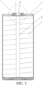
FIG. 2 is a schematic sectional diagram of a battery provided by an embodiment of the present application. -
FIG. 3 is a schematic partial enlarged diagram of part A ofFIG. 2 . -
- 1, current collecting plate; 11, main body part; 12, welding part; 13, hollow groove; 14, linear solder joint; 15, central part;
- 2, roll core; 21, receiving hole; 3, pole; 31, recess part; 301, large end; 302, small end;
- 4, insulating component; 41, first insulating component; 42, second insulating component; 421, first part; 422, second part; 43, third insulating component; 44, fourth insulating component; 441, third part; 442, fourth part; 5, housing.
- In description of the present application, terms indicating orientation or location relationships such as "center", "up", "down", "left", "right", "vertical", "horizontal", "inside", and "outside" are based on orientation or location relationships shown in drawings, which are only for a convenience of description and simplified operation, rather than indicating or implying that devices or elements referred to must have a specific orientation, be constructed and operated in a specific orientation, so it cannot be understood as a limitation of the present disclosure. In addition, terms "first" and "second" are only used to distinguish in terms of description and have no special meanings. Terms "first position" and "second position" are two different positions.
- Unless otherwise specified and defined, terms "installed", "joined", "connected", and "fixed" should be understood in a broad sense, for example, it may be a fixed connection, or a detachable connection; it may be a mechanical connection or an electrical connection; it may be a directly connection or an indirectly connection through an intermediate media; and it may be an internal connection of two components or an interaction relationship between two components. For those skilled in the art, meanings of the above terms in the present disclosure can be understood according to situations.
- Unless otherwise specified and defined, a first feature is disposed "on" or "under" a second feature may include a direct contact between the first feature and the second feature, or a contact between the first feature and the second feature through other features rather than the direct contact. Moreover, that the first feature is disposed "above" or "up" the second feature includes that the first feature is directly above or obliquely above the second feature, or only indicate that a horizontal height of the first feature is greater than a horizontal height of the second feature. That the first feature is disposed "below", "under", or "underneath" of the second feature include that the first feature is directly below or obliquely below the second feature, or only indicate that the horizontal height of the first feature is less than the horizontal height of the second feature.
- The technical solution of the present application is further explained by the attached drawings and the specific embodiments.
- According to
FIG. 1 to FIG. 3 , a battery is provided in the present embodiment, the battery comprises aroll core 2, apole 3 and a current collecting plate 1, where theroll core 2 is welded to the current collecting plate 1, and thepole 3 is electrically connected with theroll core 2 through the current collecting plate 1. The current collecting plate 1 comprises amain body part 11 and awelding part 12, thewelding part 12 is bent relative to themain body part 11, and the current collecting plate 1 is welded with theroll core 2 through thewelding part 12. - The current collecting plate 1 is provided with the
welding part 12 bent relative to themain body part 11, and is welded with theroll core 2 by thewelding part 12. Therefore, when an internal pressure of the battery is too high and an inner portion of theroll core 2 is pulled out, theroll core 2 pulls thewelding part 12 to bend to deform, thereby avoiding a second short circuit caused by a break of a solder joint between thewelding part 12 and theroll core 2. At the same time, the inner portion of theroll core 2 is pulled out to release the pressure, thus improving safety of the battery. - As shown in
FIG. 1 , when the inner portion of theroll core 2 is pulled out, theroll core 2 is generally pulled outwards from a center thereof, themain body part 11 is connected to thewelding part 12 at a position away from a center of themain body part 11, and a free end of thewelding part 12 extends towards the center of themain body part 11. Thus, an end of thewelding part 12 close to the center of themain body part 11 is bent relative to themain body part 11, so that thewelding part 12 can better adapt for pulling out theroll core 2. - For example, as shown in
FIG. 1 , in order to reduce a binding force of themain body part 11 on asingle welding part 12 during pulling out the inner portion of theroll core 2, and to facilitate theroll core 2 to pull thewelding part 12 to bend to deform during pulling out the inner portion of theroll core 2, a plurality ofwelding parts 12 are provided, and the plurality of thewelding parts 12 are spaced from each other and around the center of themain body part 11. In the present embodiment, in consideration of an overall strength of the current collecting plate 1 and its application to a cylindrical battery, the current collecting plate 1 is configured in a plate shape, and is provided with fourwelding parts 12 with fan-ring shapes. A length of an arc where thewelding part 12 connects with themain body part 11 ranges from 5mm to 8mm, and arcs of the fourwelding parts 12 close to the center of themain body part 11 are surrounded to define acentral part 15. - As shown in
FIG. 1 , in the present embodiment, a solder joint between thewelding part 12 and theroll core 2 is alinear solder joint 14, and a plurality oflinear solder joints 14 are provided between each of thewelding parts 12 and theroll core 2, so as to provide a firm connection between thewelding part 12 and theroll core 2. In order to provide a uniform current conduct by the current collecting plate 1, the plurality of thelinear solder joints 14 on the entire current collecting plate 1 are arranged at intervals around thecentral part 15. Of course, in other embodiments, the solder joint between thewelding part 12 and theroll core 2 may not be linear, but may be arranged in a concentric circle with the center of the current collecting plate 1 as an arranging center. As long as the firm connection can be achieved and the uniform current conduct of the current collecting plate 1 is provided, the solder joint may be flexibly configured as required and not limited herein. - As shown in
FIG. 1 , ahollow groove 13 is provided between thewelding part 12 and themain body part 11 when a heat generated during welding between thewelding part 12 and theroll core 2, so as to release the heat generated during the welding and reduce an influence of a high temperature generated during the welding on other components. In addition, thehollow groove 13 is arranged around thewelding part 12 to avoid an interference with themain body part 11 during the bending of thewelding part 12. For example, a width of thehollow groove 13 ranges from 0.5 mm to 1.3 mm in consideration of the overall strength of the current collecting plate 1 and a heat dissipation effect of thehollow groove 13. - For example, as shown in
FIG. 1 to FIG. 3 , the battery further includes ahousing 5, the current collecting plate 1 and theroll core 2 are arranged in thehousing 5 to protect theroll core 2 after the welding, and an end of thepole 3 is welded to thecentral part 15 by a penetration welding to provide a current path. Due to a high thickness of thepole 3 in related technologies, the penetration welding between thepole 3 and the current collecting plate 1 is affected to a certain extent, resulting in unfirm welding between thepole 3 and the current collecting plate 1, and further separating thepole 3 from the current collecting plate 1. Therefore, another end of thepole 3 is provided with arecess part 31 for an avoidance for a laser head. As an example, a penetration layer is formed between an end face of thepole 3 close to the current collecting plate 1 and a bottom of therecess part 31, the laser head is extended into therecess part 31, and laser lights emitted from the laser head pass through the penetration layer, thereby connecting thepole 3 and the current collecting plate 1. By providing therecess part 31, a route for the laserlights penetrating pole 3 during the welding may be reduced, so that the welding between thepole 3 and the current collecting plate 1 may be more firmly. - In order to ensure a speed and a flow of a current transmitted from the
roll core 2 to thepole 3 at the same time, an area S1 of thecentral part 15 ranges from 60 mm2 to 85 mm2, and a total area S2 of thewelding parts 12 ranges from 650 mm2 to 700 mm2, a relationship between the area S1 of thecentral part 15 and the total area S2 of thewelding parts 12 satisfies: 0.085 S2 ≤ S1 ≤ 0.13 S2. In other embodiments, sizes of thecentral part 15 and thewelding parts 12 may be flexibly configured as required and not limited herein. - As shown in
FIG. 2 andFIG. 3 , in order to facilitate the laser head to extend into therecess part 31 of thepole 3, therecess part 31 in the present embodiment is a platform form with a round chamfer, and may guide the laser head to extend into thepole 3. For example, a cross section of the penetration layer is circular and a diameter of the cross section ranges from 3 mm to 8 mm, and a thickness d1 of the penetration layer ranges from 0.8 mm to 1.5 mm, and a relationship between a thickness d2 of the current collecting plate 1 and the thickness d1 of the penetration layer satisfies with: 0.3 d1 ≤ d2 ≤ d1, in consideration of a welding effect and a strength of thepole 3. Of course, in other embodiments, the shape and the diameter of the cross section of therecess part 31, the thicknesses of the penetration layer and the current collecting plate 1 may be flexibly configured as required and not limited herein. - For example, as shown in
FIG. 2 andFIG. 3 , in order to ensure a welding reliability, a receivinghole 21 is provided at the center of theroll core 2, and at the same time, a through hole is provided at a bottom of thehousing 5, and the receivinghole 21 is configured to receive a supporting component. The supporting component may pass through the through hole and be arranged in the receivinghole 21. When thepole 3 is welded with the current collecting plate 1, the supporting component may press the current collecting plate 1 against thepole 3, so that the current collecting plate 1 and the end face of thepole 3 are closely attached. After welding, the supporting component can be pulled out from the bottom of thehousing 5. For example, the support component is made of a hard metal material with a good thermal conductivity so that a heat generated in the welding of the collecting plate 1 andpole 3 can be released while the collecting plate 1 is pressed tightly. To avoid occupying too much internal space of the battery, a diameter of the receivinghole 21 ranges from 3mm to 8mm. Of course, in other embodiments, a shape and a size of the cross section of the receivinghole 21 may be flexibly configured as required and not limited herein. - For example, as shown in
FIG. 2 andFIG. 3 , the battery further includes an insulating component 4, and the insulating component 4 includes a first insulatingcomponent 41. The first insulatingcomponent 41 is sleeved on thepole 3, and arranged between thehousing 5 and the current collecting plate 1 to isolate the current collecting plate 1 from thehousing 5, avoiding a short circuit. - For example, in order to avoid an interference on the welding by bonding the first insulating
component 41 with the current collecting plate 1 during the welding of the current collecting plate 1 and thepole 3, a gap is defined between the current collecting plate 1 and the first insulatingcomponent 41. Exemplarily, a height of the gap may range from 0.05 mm to 0.2 mm. - As shown in
FIG. 2 andFIG. 3 , in order to isolate thepole 3 from thehousing 5 and avoid the short circuit, the insulating component 4 further includes a second insulatingcomponent 42, a third insulatingcomponent 43 and a fourth insulatingcomponent 44. The second insulatingcomponent 42, the third insulatingcomponent 43 and the fourth insulatingcomponent 44 are all sleeved on thepole 3 and may be connected with each other to isolate thepole 3 from thehousing 5. - For example, the
pole 3 includes alarge end 301 and asmall end 302 connected to each other, a stepped surface is defined between thelarge end 301 and thesmall end 302, thelarge end 301 is arranged above thesmall end 302, and thelarge end 301 extends out of thehousing 5. The second insulatingcomponent 42 includes afirst part 421 and asecond part 422 connected to each other, thefirst part 421 and thesecond part 422 are both cylindrical structures with through holes. Thefirst part 421 and thesecond part 422 are sleeved on thesmall end portion 302 of thepole 3. Thesecond part 422 is arranged between thepole 3 and thehousing 5, thesecond part 422 is arranged between a hole wall of the hole opened in thehousing 5 for thepole 3 to passage and an outer side wall of thesmall end 302 of thepole 3. Thefirst part 421 is extended into thehousing 5, and thefirst part 421 is closely attached to an inner side wall of thehousing 5, so as to provide a stable fixation of the second insulatingcomponent 42. The fourth insulatingcomponent 44 includes athird part 441 and afourth part 442 connected to each other, and thethird part 441 and thefourth part 442 are cylindrical structures with through holes. Thethird part 441 is sleeved on thelarge end 301 of thepole 3, and thefourth part 442 extends between the stepped surface of thepole 3 and an outer wall of thehousing 5, thefourth part 442 is arranged between a side face of thelarge end 301 close to thesmall end 302 and the outer wall of thehousing 5. The third insulatingcomponent 43 is arranged between the second insulatingcomponent 42 and the fourth insulatingcomponent 44, and is connected to the second insulatingcomponent 42 and the fourth insulatingcomponent 44 respectively. Of course, in other embodiments, the number of the insulating component 4 and a specific manner of connecting may be flexibly configured as required and not limited herein. - In the present embodiment, a process of the battery is as follows:
Firstly, theroll core 2 is welded to thewelding part 12 of the current collecting plate 1 by penetration welding. The solder joints between theroll core 2 and thewelding part 12 are a plurality of linear solder joints 14, and the plurality of the linear solder joints 14 are arranged at intervals around the center of the current collecting plate 1. During this process, the heat generated in the welding can be released by thehollow groove 13. - Secondly, after welding the
core 2 with the current collecting plate 1, theroll core 2 is arranged in thehousing 5 to protect theroll core 2, and thepole 3 and the current collecting plate 1 are connected by the penetration welding to provide the current path. - For example, by providing the
recess part 31, the laser head can extend into therecess part 31 on thepole 3 and the laser lights emitted from the laser head can pass through the penetration layer thereby connecting thepole 3 and the current collecting plate 1. In this process, the support component can pass through the through hole at the bottom of thehousing 5 and be arranged in the receivinghole 21 of theroll core 2, and the current collecting plate 1 is pressed against thepole 3, so that the current collecting plate 1 and the end face of thepole 3 are closely attached, and the heat generated during the welding can be released. After the welding, the support component can be pulled out from the through hole at the bottom of thehousing 5.
Claims (11)
- A current collecting plate, wherein the current collecting plate is configured to connect with a roll core (2) of a battery, the current collecting plate (1) comprises a main body part (11) and a welding part (12), the welding part (12) is bent relative to the main body part (11), and the current collecting plate (1) is welded with the roll core (2) through the welding part (12).
- The current collecting plate according to claim 1, wherein the main body part (11) is connected to the welding part (12) at a position away from a center of the main body part (11), and a free end of the welding part (12) extends towards the center of the main body part (11).
- The current collecting plate according to claim 1, wherein a plurality of welding parts (12) are provided, and the plurality of the welding parts (12) are arranged at intervals and around a center of the main body part (11).
- The current collecting plate according to any one of claim 1 to claim 3, wherein a hollow groove (13) is provided between the welding part (12) and the main body part (11).
- A battery, comprising a roll core (2), a pole (3), and the current collecting plate (1) according to any one of claim 1 to claim 4, wherein the roll core (2) is welded to the current collecting plate (1), and the pole (3) is electrically connected with the roll core (2) through the current collecting plate (1).
- The battery according to claim 5, wherein the main body part (11) comprises a central part (15), a first end of the pole (3) is welded to the central part (15), and a second end of the pole (3) is provided with a recess part (31) configured for an avoidance for a laser head.
- The battery according to claim 6, wherein an area S1 of the central part (15) ranges from 60 mm2 to 85 mm2, and a total area S2 of the welding part (12) ranges from 650 mm2 to 700 mm2;
a relationship between the area S1 of the central part (15) and the total area S2 of the welding part (12) satisfies with: 0.085 S2 ≤ S1 ≤ 0.13 S2. - The battery according to claim 6, wherein a penetration layer is provided between an end face of the pole (3) close to the current collecting plate (1) and an inner bottom surface of the recess part (31), a cross section of the penetration layer is circular and a diameter of the cross section ranges from 3mm to 8mm, and a thickness d1 of the penetration layer ranges from 0.8 mm to 1.5 mm;
wherein a relationship between a thickness d2 of the current collecting plate (1) and the thickness d1 of the penetration layer satisfies with: 0.3 d1 ≤ d2 ≤ d1. - The battery according to any one of claim 5 to claim 8, wherein a center of the roll core (2) is provided with a receiving hole (21), the receiving hole (21) is configured to receive a support component, and the support component is configured to press the current collecting plate (1) against the pole (3).
- The battery according to any one of claim 5 to claim 8, further comprising an insulating component (4) and a housing (5), wherein the current collecting plate (1) and the roll core (2) are arranged in the housing (5), the insulating component (4) comprises a first insulating component (41), and the first insulating component (41) is sleeved on the pole (3) and arranged between the housing (5) and the current collecting plate (1).
- The battery according to claim 10, wherein a gap is defined between the current collecting plate (1) and the first insulating component (41).
Applications Claiming Priority (2)
| Application Number | Priority Date | Filing Date | Title |
|---|---|---|---|
| CN202222108617.8U CN218039702U (en) | 2022-08-11 | 2022-08-11 | A current collecting plate and battery |
| PCT/CN2022/127922 WO2024031841A1 (en) | 2022-08-11 | 2022-10-27 | Current collector disc and battery |
Publications (2)
| Publication Number | Publication Date |
|---|---|
| EP4343951A1 true EP4343951A1 (en) | 2024-03-27 |
| EP4343951A4 EP4343951A4 (en) | 2024-10-30 |
Family
ID=84344853
Family Applications (1)
| Application Number | Title | Priority Date | Filing Date |
|---|---|---|---|
| EP22826582.3A Pending EP4343951A4 (en) | 2022-08-11 | 2022-10-27 | CURRENT COLLECTOR DISC AND BATTERY |
Country Status (6)
| Country | Link |
|---|---|
| US (1) | US20240304955A1 (en) |
| EP (1) | EP4343951A4 (en) |
| CN (1) | CN218039702U (en) |
| DE (1) | DE212022000419U1 (en) |
| HU (1) | HU6035U (en) |
| WO (1) | WO2024031841A1 (en) |
Families Citing this family (8)
| Publication number | Priority date | Publication date | Assignee | Title |
|---|---|---|---|---|
| CN116111289A (en) * | 2023-02-10 | 2023-05-12 | 惠州亿纬锂能股份有限公司 | Converging disc structure and battery pack |
| CN219498121U (en) * | 2023-02-27 | 2023-08-08 | 远景动力技术(江苏)有限公司 | Battery cell and electricity utilization device comprising same |
| CN219350579U (en) * | 2023-03-23 | 2023-07-14 | 欣旺达电动汽车电池有限公司 | A battery and an electrical device |
| JP7800520B2 (en) * | 2023-09-20 | 2026-01-16 | トヨタ自動車株式会社 | Energy storage cell |
| CN118054164A (en) * | 2024-03-31 | 2024-05-17 | 惠州亿纬动力电池有限公司 | Current collecting plate and battery |
| CN222940146U (en) * | 2024-07-17 | 2025-06-03 | 株式会社Aesc日本 | Batteries and Electronics |
| CN223297009U (en) * | 2024-09-20 | 2025-09-02 | 浙江锂欣能源科技有限公司 | Cylindrical battery and electronic equipment |
| KR20260101644A (en) * | 2024-12-23 | 2026-06-30 | 주식회사 엘지에너지솔루션 | Battery cell, Battery pack and Vehicle comprising same |
Family Cites Families (9)
| Publication number | Priority date | Publication date | Assignee | Title |
|---|---|---|---|---|
| JP4524982B2 (en) * | 2002-10-16 | 2010-08-18 | パナソニック株式会社 | Cylindrical secondary battery |
| CN208284546U (en) * | 2018-04-20 | 2018-12-25 | 苏州安靠电源有限公司 | Cylindrical battery and its electrode current collecting component |
| CN215578675U (en) * | 2021-05-21 | 2022-01-18 | 湖北亿纬动力有限公司 | Assembly structure of positive pole and positive collector plate, battery, battery module and battery pack |
| CN215578674U (en) * | 2021-05-21 | 2022-01-18 | 湖北亿纬动力有限公司 | Assembling structure of positive pole and positive current collecting plate and battery |
| CN215816074U (en) * | 2021-08-19 | 2022-02-11 | 厦门海辰新能源科技有限公司 | Battery core assembly and battery |
| CN217062428U (en) * | 2021-12-21 | 2022-07-26 | 云山新能源材料技术(深圳)有限公司 | Converging sheet structure and cylindrical battery |
| CN216720227U (en) * | 2022-01-28 | 2022-06-10 | 蓝京新能源(嘉兴)有限公司 | Manifold disc assembly for battery |
| CN114628866A (en) * | 2022-03-28 | 2022-06-14 | 蓝京新能源(嘉兴)有限公司 | A high energy density cylindrical battery and its assembly process |
| CN114628767B (en) * | 2022-03-28 | 2023-09-29 | 蓝京新能源(嘉兴)有限公司 | A cylindrical battery and its assembly process |
-
2022
- 2022-08-11 CN CN202222108617.8U patent/CN218039702U/en active Active
- 2022-10-27 EP EP22826582.3A patent/EP4343951A4/en active Pending
- 2022-10-27 DE DE212022000419.1U patent/DE212022000419U1/en active Active
- 2022-10-27 WO PCT/CN2022/127922 patent/WO2024031841A1/en not_active Ceased
- 2022-10-27 US US18/003,347 patent/US20240304955A1/en active Pending
- 2022-10-27 HU HUU2400294U patent/HU6035U/en unknown
Also Published As
| Publication number | Publication date |
|---|---|
| US20240304955A1 (en) | 2024-09-12 |
| WO2024031841A1 (en) | 2024-02-15 |
| CN218039702U (en) | 2022-12-13 |
| EP4343951A4 (en) | 2024-10-30 |
| HU6035U (en) | 2026-03-28 |
| DE212022000419U1 (en) | 2025-04-30 |
Similar Documents
| Publication | Publication Date | Title |
|---|---|---|
| US20240304955A1 (en) | Current collecting plate and battery | |
| EP3651229B1 (en) | Secondary battery and method of manufacturing the secondary battery | |
| US10763466B2 (en) | Top cap assembly of a secondary battery, and secondary battery | |
| EP3731297B1 (en) | Battery module | |
| US20200280043A1 (en) | Secondary battery | |
| US20120040215A1 (en) | Battery safety vent and battery with the same | |
| EP3926755B1 (en) | Battery, manufacturing method thereof and electronic product | |
| CN111370635B (en) | Production method of button cell without welding trace and prepared button cell | |
| CN118156736B (en) | Battery monomer and battery pack | |
| TWI499150B (en) | Modular current interrupt device, battery and method of manufacturing the same | |
| EP4398387A1 (en) | Top cover structure and battery | |
| CN113422166A (en) | Connecting piece, battery monomer and battery package | |
| CN120109449A (en) | Battery cover and battery | |
| EP3474342A1 (en) | Battery cap assembly and secondary battery | |
| CN222620070U (en) | Battery | |
| CN206742419U (en) | Secondary cell | |
| CN113422168A (en) | Current collector assembly, battery monomer and battery pack | |
| CN103456914A (en) | Battery provided with a safety snap device and convenient to weld | |
| CN218887263U (en) | Lithium battery | |
| WO2026103227A1 (en) | Battery cover plate and battery | |
| CN222637601U (en) | Battery cell | |
| CN218300003U (en) | Battery with a battery cell | |
| CN218039707U (en) | A battery module and a power battery comprising the same | |
| CN217691559U (en) | Connecting piece, battery monomer and battery package | |
| CN217691564U (en) | Current collector assembly, battery monomer and battery pack |
Legal Events
| Date | Code | Title | Description |
|---|---|---|---|
| STAA | Information on the status of an ep patent application or granted ep patent |
Free format text: STATUS: UNKNOWN |
|
| STAA | Information on the status of an ep patent application or granted ep patent |
Free format text: STATUS: THE INTERNATIONAL PUBLICATION HAS BEEN MADE |
|
| PUAI | Public reference made under article 153(3) epc to a published international application that has entered the european phase |
Free format text: ORIGINAL CODE: 0009012 |
|
| STAA | Information on the status of an ep patent application or granted ep patent |
Free format text: STATUS: REQUEST FOR EXAMINATION WAS MADE |
|
| 17P | Request for examination filed |
Effective date: 20221228 |
|
| AK | Designated contracting states |
Kind code of ref document: A1 Designated state(s): AL AT BE BG CH CY CZ DE DK EE ES FI FR GB GR HR HU IE IS IT LI LT LU LV MC ME MK MT NL NO PL PT RO RS SE SI SK SM TR |
|
| A4 | Supplementary search report drawn up and despatched |
Effective date: 20240927 |
|
| RIC1 | Information provided on ipc code assigned before grant |
Ipc: H01M 50/502 20210101AFI20240924BHEP |
|
| STAA | Information on the status of an ep patent application or granted ep patent |
Free format text: STATUS: EXAMINATION IS IN PROGRESS |
|
| 17Q | First examination report despatched |
Effective date: 20251009 |
|
| DAV | Request for validation of the european patent (deleted) | ||
| DAX | Request for extension of the european patent (deleted) | ||
| GRAP | Despatch of communication of intention to grant a patent |
Free format text: ORIGINAL CODE: EPIDOSNIGR1 |
|
| STAA | Information on the status of an ep patent application or granted ep patent |
Free format text: STATUS: GRANT OF PATENT IS INTENDED |
|
| INTG | Intention to grant announced |
Effective date: 20260612 |