EP4343945A1 - Battery module for preventing chain ignition and method for manufacturing same - Google Patents
Battery module for preventing chain ignition and method for manufacturing same Download PDFInfo
- Publication number
- EP4343945A1 EP4343945A1 EP23737359.2A EP23737359A EP4343945A1 EP 4343945 A1 EP4343945 A1 EP 4343945A1 EP 23737359 A EP23737359 A EP 23737359A EP 4343945 A1 EP4343945 A1 EP 4343945A1
- Authority
- EP
- European Patent Office
- Prior art keywords
- cell
- seating
- vent
- battery
- battery module
- Prior art date
- Legal status (The legal status is an assumption and is not a legal conclusion. Google has not performed a legal analysis and makes no representation as to the accuracy of the status listed.)
- Pending
Links
Images




Classifications
-
- H—ELECTRICITY
- H01—ELECTRIC ELEMENTS
- H01M—PROCESSES OR MEANS, e.g. BATTERIES, FOR THE DIRECT CONVERSION OF CHEMICAL ENERGY INTO ELECTRICAL ENERGY
- H01M50/00—Constructional details or processes of manufacture of the non-active parts of electrochemical cells other than fuel cells, e.g. hybrid cells
- H01M50/20—Mountings; Secondary casings or frames; Racks, modules or packs; Suspension devices; Shock absorbers; Transport or carrying devices; Holders
- H01M50/204—Racks, modules or packs for multiple batteries or multiple cells
- H01M50/207—Racks, modules or packs for multiple batteries or multiple cells characterised by their shape
- H01M50/213—Racks, modules or packs for multiple batteries or multiple cells characterised by their shape adapted for cells having curved cross-section, e.g. round or elliptic
-
- H—ELECTRICITY
- H01—ELECTRIC ELEMENTS
- H01M—PROCESSES OR MEANS, e.g. BATTERIES, FOR THE DIRECT CONVERSION OF CHEMICAL ENERGY INTO ELECTRICAL ENERGY
- H01M50/00—Constructional details or processes of manufacture of the non-active parts of electrochemical cells other than fuel cells, e.g. hybrid cells
- H01M50/20—Mountings; Secondary casings or frames; Racks, modules or packs; Suspension devices; Shock absorbers; Transport or carrying devices; Holders
- H01M50/233—Mountings; Secondary casings or frames; Racks, modules or packs; Suspension devices; Shock absorbers; Transport or carrying devices; Holders characterised by physical properties of casings or racks, e.g. dimensions
- H01M50/24—Mountings; Secondary casings or frames; Racks, modules or packs; Suspension devices; Shock absorbers; Transport or carrying devices; Holders characterised by physical properties of casings or racks, e.g. dimensions adapted for protecting batteries from their environment, e.g. from corrosion
-
- H—ELECTRICITY
- H01—ELECTRIC ELEMENTS
- H01M—PROCESSES OR MEANS, e.g. BATTERIES, FOR THE DIRECT CONVERSION OF CHEMICAL ENERGY INTO ELECTRICAL ENERGY
- H01M50/00—Constructional details or processes of manufacture of the non-active parts of electrochemical cells other than fuel cells, e.g. hybrid cells
- H01M50/20—Mountings; Secondary casings or frames; Racks, modules or packs; Suspension devices; Shock absorbers; Transport or carrying devices; Holders
- H01M50/262—Mountings; Secondary casings or frames; Racks, modules or packs; Suspension devices; Shock absorbers; Transport or carrying devices; Holders with fastening means, e.g. locks
- H01M50/264—Mountings; Secondary casings or frames; Racks, modules or packs; Suspension devices; Shock absorbers; Transport or carrying devices; Holders with fastening means, e.g. locks for cells or batteries, e.g. straps, tie rods or peripheral frames
-
- H—ELECTRICITY
- H01—ELECTRIC ELEMENTS
- H01M—PROCESSES OR MEANS, e.g. BATTERIES, FOR THE DIRECT CONVERSION OF CHEMICAL ENERGY INTO ELECTRICAL ENERGY
- H01M50/00—Constructional details or processes of manufacture of the non-active parts of electrochemical cells other than fuel cells, e.g. hybrid cells
- H01M50/20—Mountings; Secondary casings or frames; Racks, modules or packs; Suspension devices; Shock absorbers; Transport or carrying devices; Holders
- H01M50/289—Mountings; Secondary casings or frames; Racks, modules or packs; Suspension devices; Shock absorbers; Transport or carrying devices; Holders characterised by spacing elements or positioning means within frames, racks or packs
- H01M50/291—Mountings; Secondary casings or frames; Racks, modules or packs; Suspension devices; Shock absorbers; Transport or carrying devices; Holders characterised by spacing elements or positioning means within frames, racks or packs characterised by their shape
-
- H—ELECTRICITY
- H01—ELECTRIC ELEMENTS
- H01M—PROCESSES OR MEANS, e.g. BATTERIES, FOR THE DIRECT CONVERSION OF CHEMICAL ENERGY INTO ELECTRICAL ENERGY
- H01M50/00—Constructional details or processes of manufacture of the non-active parts of electrochemical cells other than fuel cells, e.g. hybrid cells
- H01M50/30—Arrangements for facilitating escape of gases
- H01M50/342—Non-re-sealable arrangements
- H01M50/3425—Non-re-sealable arrangements in the form of rupturable membranes or weakened parts, e.g. pierced with the aid of a sharp member
-
- H—ELECTRICITY
- H01—ELECTRIC ELEMENTS
- H01M—PROCESSES OR MEANS, e.g. BATTERIES, FOR THE DIRECT CONVERSION OF CHEMICAL ENERGY INTO ELECTRICAL ENERGY
- H01M50/00—Constructional details or processes of manufacture of the non-active parts of electrochemical cells other than fuel cells, e.g. hybrid cells
- H01M50/30—Arrangements for facilitating escape of gases
- H01M50/35—Gas exhaust passages comprising elongated, tortuous or labyrinth-shaped exhaust passages
- H01M50/367—Internal gas exhaust passages forming part of the battery cover or case; Double cover vent systems
-
- H—ELECTRICITY
- H01—ELECTRIC ELEMENTS
- H01M—PROCESSES OR MEANS, e.g. BATTERIES, FOR THE DIRECT CONVERSION OF CHEMICAL ENERGY INTO ELECTRICAL ENERGY
- H01M50/00—Constructional details or processes of manufacture of the non-active parts of electrochemical cells other than fuel cells, e.g. hybrid cells
- H01M50/30—Arrangements for facilitating escape of gases
- H01M50/383—Flame arresting or ignition-preventing means
-
- Y—GENERAL TAGGING OF NEW TECHNOLOGICAL DEVELOPMENTS; GENERAL TAGGING OF CROSS-SECTIONAL TECHNOLOGIES SPANNING OVER SEVERAL SECTIONS OF THE IPC; TECHNICAL SUBJECTS COVERED BY FORMER USPC CROSS-REFERENCE ART COLLECTIONS [XRACs] AND DIGESTS
- Y02—TECHNOLOGIES OR APPLICATIONS FOR MITIGATION OR ADAPTATION AGAINST CLIMATE CHANGE
- Y02E—REDUCTION OF GREENHOUSE GAS [GHG] EMISSIONS, RELATED TO ENERGY GENERATION, TRANSMISSION OR DISTRIBUTION
- Y02E60/00—Enabling technologies; Technologies with a potential or indirect contribution to GHG emissions mitigation
- Y02E60/10—Energy storage using batteries
Definitions
- the present invention relates to a battery module for preventing chain ignition and a manufacturing method thereof, and more particularly, relates to a battery module for preventing chain ignition capable of smoothly ejecting flames generated when a battery cell is ignited inside and preventing the flames from spreading to adjacent battery cells, and a manufacturing method thereof.
- Figures 1 and 2 are diagrams for explaining a battery module according to a prior art.
- a conventional battery module comprises at least one battery cell (10), a cell frame (20), an upper cover (40) and a lower cover (50).
- the battery cell (10) comprises positive and negative current collectors, separators, an active material, an electrolytes, and the like, which can be repeatedly charged and discharged by electrochemical reactions between the components. Since the battery module is manufactured in the form that these battery cells (10) are densely packed in a narrow space, it is important to easily release heat generated from each battery cell (10).
- the process of charging or discharging the battery cell (10) is performed by an electrochemical reaction, so that if the heat of the battery module generated during the charging and discharging process is not effectively removed, heat accumulation occurs, and as a result, the deterioration of the battery module is accelerated, where ignition or explosion may optionally occur.
- At least one battery cell (10) is spaced apart from the cell frame (20). At least one battery cell (10) is fixed to the cell frame (20). Referring to Figure 2 , each battery cell (10) is fixed to the cell frame (20) by an adhesive (30) applied to the side of the battery cell (10).
- the cell frame (20) has, as a structure with opened top and bottom, a structure to support battery cells (10) so that the vent part (11) of at least one battery cell (10) is mutually exposed.
- An upper cover (40) and a lower cover (50) are installed on the cell frame (20).
- the upper cover (40) is installed on the top of the cell frame (20) to cover the opened top of the cell frame (20).
- the lower cover (50) is installed on the bottom of the cell frame (20) to cover the opened bottom of the cell frame (20).
- the present invention is intended to provide a battery module for preventing chain ignition comprising a cell frame for blocking vent parts of battery cells from being exposed to the outside, and a manufacturing method thereof.
- the present invention is intended to provide a battery module for preventing chain ignition in which upon inside ignition of a battery cell, as only the cell frame portion covering the ignited battery cell is individually damaged, the flames generated upon the inside ignition of the battery cell can be smoothly ejected through the damaged portion, and a manufacturing method thereof.
- the present invention is intended to provide a battery module for preventing chain ignition capable of preventing flames from spreading to adjacent battery cells while only specific parts of a cell frame are individually damaged, and a manufacturing method thereof.
- a battery module for preventing chain ignition comprises a plurality of battery cells having vent parts, a cell frame including a cell seating part having a plurality of seating grooves provided so that the vent parts of the plurality of battery cells are each inserted, and a first adhesive layer disposed between the vent parts of the battery cells and the seating grooves, and for bonding the battery cells to the cell seating part.
- the cell seating part is provided so that two adjacent seating grooves are located apart from each other.
- each seating groove may be provided to be recessed on one inside surface of the cell frame facing the vent parts.
- the seating groove has a seating groove bottom surface positioned to face the vent part and a seating groove side surface connecting the seating groove bottom surface and one inside surface of the cell frame.
- the first adhesive layer may be positioned in each of a space between the seating groove bottom surface and the vent part and a space between the seating groove side surface and the battery cell.
- the first adhesive layer may be formed by applying an adhesive material to one inside surface of the cell frame including the seating groove bottom surface and the seating groove side surface.
- the first adhesive layer may be provided to surround each of the plurality of seating grooves.
- the cell seating part may have a plurality of vent pattern grooves each formed on one outside surface in an opposite direction to one inside surface of the cell frame. Furthermore, each of the vent pattern grooves may be positioned so that a partial region overlaps with the seating groove located in the opposite direction.
- each vent pattern groove may be arranged so that its center is positioned coaxially with the center of the seating groove located in the opposite direction.
- each vent pattern groove may have a diameter smaller than the diameter of the seating groove.
- the cell seating part may have a collision wall part positioned between the seating groove and the vent pattern groove.
- the collision wall part may comprise a region with the smallest thickness in the cell frame.
- the collision wall part may be provided to be damaged when the battery cell inserted into the seating groove is ignited.
- the depth of the vent pattern groove may be smaller than the depth of the seating groove.
- the cell frame may be injection-molded such that the plurality of seating grooves is provided on one inside surface of the cell frame and the plurality of vent pattern grooves is provided on one outside surface of the cell frame.
- the cell seating part may be provided so that adjacent seating grooves are partitioned from each other, and provided so that seating grooves surrounding battery cells in which inside ignition has occurred are individually damaged.
- the battery module may comprise a cell support having a plurality of insertion holes into which each battery cell is inserted, and mounted on the cell frame.
- the battery module may comprise a cover part surrounding the cell support part and mounted on the cell frame to accommodate the plurality of battery cells.
- the battery module may comprise a second adhesive layer for bonding the plurality of battery cells to the cover part.
- the battery module for preventing chain ignition related to at least one example of the present invention and the manufacturing method thereof have the following effects.
- the flames generated upon the inside ignition of the battery cell can be smoothly ejected through the damaged portion.
- Figure 3 schematically illustrates an exploded perspective diagram of a battery module (100) for preventing chain ignition according to one example of the present invention
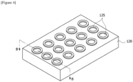
- Figure 4 illustrates, in one example of the present invention, a cell frame (120) provided with at least one vent pattern groove, viewed from the outside of the cell frame (120).
- Figure 5 schematically illustrates a cross-sectional diagram of a cell frame according to one example of the present invention
- Figure 6 schematically illustrates, in one example of the present invention, a combined cross-section of a cell seating part, a first adhesive layer, and a battery cell in a state where the battery cell is bonded to the cell seating part.
- Figure 7 is a diagram for explaining, in a battery module for preventing chain ignition according to one example of the present invention, that upon inside ignition of any one of battery cells, flames are ejected to the outside of a cell frame, while a collision wall part of a cell seating part is damaged.
- the battery module (100) for preventing chain ignition comprises a plurality of battery cells (110) having vent parts (111), a cell frame (120) including a cell seating part (121) having a plurality of seating grooves (123) provided so that the vent parts (111) of the plurality of battery cells (110) are each inserted, and a first adhesive layer (140) disposed between the vent parts (111) of the battery cells (110) and the seating grooves (123), and for bonding the battery cells (110) to the cell seating part (121).
- a vent part (111) is provided at one end of a cylindrical battery cell (110).
- the vent part (111) is formed along one end edge of the battery cell (110).
- the vent part (111) may be formed at the central position of one end of the battery cell (110).
- the vent part (111) is for relieving internal pressure of the battery cell (110).
- the vent part (111) is formed at one end of the battery cell (110) to have a relatively weak strength, and is provided to be broken upon inside ignition of the battery cell (110).
- the vent part (111) is for relieving the internal pressure of the battery cell (110), while the vent part (111) is broken from the battery cell (110).
- the present invention can prevent flames from spreading to adjacent battery cells (110) upon inside ignition of a battery cell (110) while only a specific portion of the cell frame (120) covering the ignited battery cell (110) upon the inside ignition of the battery cell (110) is damaged.
- the battery module (100) for preventing chain ignition may comprise a plurality of battery cells (110), a cell frame (120), a cell seating part (121), a first adhesive layer (140), a cell support part (150), and a cover part (170).
- the battery cell (110) according to this example may be a cylindrical battery cell (110), where a vent part (111) is provided at one end.
- the cell frame (120) has a structure that is open toward the vent parts of the plurality of battery cells.
- the plurality of battery cells (110) is inserted into the cell frame (120).
- a cell seating part (121) is provided in the cell frame (120).
- the cell seating part (121) refers to a region of the cell frame (120) surrounding the vent parts (111) of the battery cells (110).
- the cell seating part (121) may be provided so that the respective seating grooves (123) are partitioned from each other.
- the cell seating part (121) is provided such that two adjacent seating grooves (123) are located apart from each other.
- each seating groove (123) may be provided to be recessed on one inside surface of the cell frame (120) facing the vent parts (111).
- the cell seating part (121) may be provided so that adjacent seating grooves (123) are partitioned from each other, and provided so that seating grooves surrounding battery cells (110) in which inside ignition has occurred are individually damaged. That is, the cell seating part (121) may be provided so that upon the inside ignition of the battery cells (110), the seating grooves (123) in contact with the vent parts (111) of the battery cells are individually damaged.
- the cell seating part (121) may be provided to support the end of each battery cell (110) where the vent part is located while surrounding the vent part (111) of each battery cell.
- the cell seating part (121) may have a plurality of seating grooves (123) and a plurality of vent pattern grooves (125).
- the cell seating part (121) may have a plurality of vent pattern grooves (125) each formed on one outside surface in an opposite direction to one inside surface of the cell frame (120).
- each of the vent pattern grooves (125) may be positioned so that a partial region overlaps with the seating groove (123) located in the opposite direction.
- the plurality of seating grooves (123) may be arranged to correspond to an arrangement pattern of the plurality of battery cells (110).
- the plurality of vent pattern grooves (125) may be arranged to correspond to the arrangement pattern of the plurality of vent parts (111).
- the number of seating grooves and the number of vent pattern grooves may be provided to be the same, and as in Figure 4 , when viewed from the top of the cell frame (120), the vent pattern grooves on one outside surface of the cell frame may be matched with the seating grooves on one inside surface of the cell frame in a ratio of 1:1.
- the respective seating grooves (123) are provided to be stepped on one inside surface of the cell frame (120).
- the seating groove (123) has a shape corresponding to the shape of one end of the battery cell (110) where the vent part is located, which is provided to allow the battery cells (110) to be inserted.
- the seating groove (123) has a seating groove bottom surface (123a) and a seating groove side surface (123b). That is, the seating groove (123) has a seating groove bottom surface (123a) positioned to face the vent part (111) and a seating groove side surface (123b) connecting the seating groove bottom surface (123a) and one inside surface of the cell frame.
- the seating groove side surface (123b) is provided to surround the end side surface of the battery cell (110).
- the cell seating part (121) is disposed so that the seating groove bottom surface (123a) faces the vent part (111), and the seating groove side surface (123b) surrounds the end side surface of the battery cell (110).
- the respective vent parts (111) are located inside the seating groove (123) to be individually partitioned.
- vent pattern grooves (125) are each arranged to correspond to one seating groove (123) on one outside surface of the cell frame (120).
- each of the vent pattern grooves (125) may be arranged such that its center is positioned coaxially with the center of the seating groove (123) located in the opposite direction.
- each vent pattern groove (125) may have a diameter smaller than the diameter of the seating groove (123).
- the depth (D 2 ) of the vent pattern groove (125) is smaller than the depth (Di) of the seating groove (123) and the diameter is smaller than the diameter of the seating groove (123).
- one outside surface of the cell frame (120) is the opposite side of one inside surface of the cell frame (120). That is, based on the thickness direction of the cell frame (120), the plurality of seating grooves (123) is provided on the inside, and the plurality of vent pattern grooves (125) is provided on the outside.
- the cell seating part (120) may have a collision wall part (124) located between the seating groove and the vent pattern groove.
- one region of the cell frame (120) between the seating groove (123) and the vent pattern groove (125) is referred to as the "collision wall part (124)".
- the collision wall part (124) may comprise a region having the smallest thickness in the cell frame (120). With this structure, the collision wall part (124) may be provided to be damaged prior to other regions of the cell frame when the battery cell inserted into the seating groove (123) is ignited.
- the collision wall part (124) is provided such that it is recessed into the inside surface of the cell frame (120) by the depth of the seating groove (123), and recessed into the outside surface of the cell frame (120) by the depth of the vent pattern groove (125).
- the collision wall part (124) may have a thickness (T 2 ) obtained by subtracting the depth of the vent pattern groove (125) and the depth of the seating groove (123) from the reference thickness (T 1 ), which is the thickness of the cell frame (120).
- the vent pattern groove (125) is formed at a position overlapping each seating groove (123), the thickness of the collision wall part (124) can be reduced.
- the thickness of the collision wall part (124), which is a portion in contact with the vent part (111), is reduced, and as a result, upon the inside ignition of the battery cell (110), the collision wall part (124) may be damaged while the vent part (111) is broken in the battery cell (110).
- flames ejected from the ignited battery cell (110) may be ejected through the damaged collision wall part, and the flames may be prevented from being transferred to the surrounding battery cells (110).
- the cell frame (120) having such a structure may be injection-molded so that the cell seating part (121) is provided.
- the cell frame (120) may be injection-molded such that the plurality of seating grooves (123) is provided on one inside surface of the cell frame and the plurality of vent pattern grooves (125) is provided on one outside surface of the cell frame.
- each battery cell (110) may be bonded to each seating groove (123) by a first adhesive layer (140).
- the first adhesive layer (140) bonds, in one inside surface of the cell frame (120), one end of the battery cell (110) to each seating groove (123).
- the first adhesive layer (140) may be positioned in each of a space between the seating groove bottom surface (123a) and the vent part (111) and a space between the seating groove side surface (123b) and the battery cell.
- the first adhesive layer (140) may be formed by applying an adhesive material to one inside surface of the cell frame including the seating groove bottom surface and the seating groove side surface.
- the first adhesive layer (140) may be provided to surround each of the plurality of seating grooves (123).
- the first adhesive layer (140) may be formed by applying an adhesive material to one inside surface of the cell frame (120) including the seating groove bottom surface (123a) and the seating groove side surface (123b), and the first adhesive layer (140) may bond each battery cell (110) to each seating groove (123).
- the first adhesive layer (140) is in a form such as a double-sided tape, wherein one side may be bonded to one inside surface of the cell frame (120) and the end of the battery cell (110) where the vent part is located may be bonded to the other side.
- the first adhesive layer (140) is formed of a material capable of bonding the battery cell (110) to the seating groove (123) in a laterally supportable manner, various types of materials may be used, and the material is not limited to a specific material.
- the battery module (100) may comprise a cell support part (150) having a plurality of insertion holes (151), into which each battery cell (110) is inserted, and mounted on the cell frame.
- the cell support part (150) is inserted into the inner space (127) of the cell frame (120) and mounted on the cell frame (120).
- the cell support part (150) may support the plurality of battery cells (110) to be located apart at regular intervals.
- the cell support part (150) has a plurality of insertion holes (151) provided in an arrangement pattern of the plurality of battery cells.
- the insertion hole (151) laterally supports the battery cell while surrounding the side surface of the battery cell.
- the battery module (100) may comprise a cover part (170) surrounding the cell support part (150), and mounted on the cell frame (120) to accommodate the plurality of battery cells.
- the cover part (170) is mounted on the cell frame (120) to face the cell seating part (121).
- the cover part (170) surrounds the inner space (127) of the cell frame (120) so that the plurality of battery cells (110) is not exposed to the outside.
- the battery module (100) may comprise a second adhesive layer (160) for bonding the plurality of battery cells (110) to the cover part (170).
- the second adhesive layer (160) bonds the ends of the plurality of battery cells (110) to the inner surface of the cover part (170).
- the second adhesive layer (160) is positioned between the cover part (170) and the end of the battery cell (110) where the vent part (111) is not provided.
- the second adhesive layer (160) may be made of the same adhesive or adhesive sheet as the adhesive layer (140) as described above.
- the present invention may slim the thickness of the collision wall part (124) of the cell frame (120), which is a portion covering the vent part (111) of each battery cell.
- the vent part (111) broken in the battery cell (110) upon the inside ignition of the battery cell (110) damages the collision wall part (124), the flames generated from the battery cell (110) may be smoothly discharged to the outside through the damaged collision wall part (124).
Landscapes
- Chemical & Material Sciences (AREA)
- Chemical Kinetics & Catalysis (AREA)
- Electrochemistry (AREA)
- General Chemical & Material Sciences (AREA)
- Battery Mounting, Suspending (AREA)
- Gas Exhaust Devices For Batteries (AREA)
Abstract
Description
- The present invention relates to a battery module for preventing chain ignition and a manufacturing method thereof, and more particularly, relates to a battery module for preventing chain ignition capable of smoothly ejecting flames generated when a battery cell is ignited inside and preventing the flames from spreading to adjacent battery cells, and a manufacturing method thereof.
-
Figures 1 and2 are diagrams for explaining a battery module according to a prior art. - Referring to
Figure 1 , a conventional battery module comprises at least one battery cell (10), a cell frame (20), an upper cover (40) and a lower cover (50). - The battery cell (10) comprises positive and negative current collectors, separators, an active material, an electrolytes, and the like, which can be repeatedly charged and discharged by electrochemical reactions between the components. Since the battery module is manufactured in the form that these battery cells (10) are densely packed in a narrow space, it is important to easily release heat generated from each battery cell (10).
- The process of charging or discharging the battery cell (10) is performed by an electrochemical reaction, so that if the heat of the battery module generated during the charging and discharging process is not effectively removed, heat accumulation occurs, and as a result, the deterioration of the battery module is accelerated, where ignition or explosion may optionally occur.
- At least one battery cell (10) is spaced apart from the cell frame (20). At least one battery cell (10) is fixed to the cell frame (20). Referring to
Figure 2 , each battery cell (10) is fixed to the cell frame (20) by an adhesive (30) applied to the side of the battery cell (10). - The cell frame (20) has, as a structure with opened top and bottom, a structure to support battery cells (10) so that the vent part (11) of at least one battery cell (10) is mutually exposed.
- An upper cover (40) and a lower cover (50) are installed on the cell frame (20). The upper cover (40) is installed on the top of the cell frame (20) to cover the opened top of the cell frame (20). The lower cover (50) is installed on the bottom of the cell frame (20) to cover the opened bottom of the cell frame (20).
- In the conventional battery module, when any one of the battery cells (10) is ignited inside, there has been a problem in which chain ignition occurs, while the vent part (11) is opened in the battery cell (10) by the flames generated in the ignited battery cell (10), and simultaneously the flames of the ignited battery cell (10) are transferred to the surrounding battery cells (10).
- The present invention is intended to provide a battery module for preventing chain ignition comprising a cell frame for blocking vent parts of battery cells from being exposed to the outside, and a manufacturing method thereof.
- Also, the present invention is intended to provide a battery module for preventing chain ignition in which upon inside ignition of a battery cell, as only the cell frame portion covering the ignited battery cell is individually damaged, the flames generated upon the inside ignition of the battery cell can be smoothly ejected through the damaged portion, and a manufacturing method thereof.
- In addition, the present invention is intended to provide a battery module for preventing chain ignition capable of preventing flames from spreading to adjacent battery cells while only specific parts of a cell frame are individually damaged, and a manufacturing method thereof.
- A battery module for preventing chain ignition according to one example of the present invention comprises a plurality of battery cells having vent parts, a cell frame including a cell seating part having a plurality of seating grooves provided so that the vent parts of the plurality of battery cells are each inserted, and a first adhesive layer disposed between the vent parts of the battery cells and the seating grooves, and for bonding the battery cells to the cell seating part.
- Also, the cell seating part is provided so that two adjacent seating grooves are located apart from each other.
- In addition, each seating groove may be provided to be recessed on one inside surface of the cell frame facing the vent parts.
- Furthermore, the seating groove has a seating groove bottom surface positioned to face the vent part and a seating groove side surface connecting the seating groove bottom surface and one inside surface of the cell frame.
- Also, the first adhesive layer may be positioned in each of a space between the seating groove bottom surface and the vent part and a space between the seating groove side surface and the battery cell.
- In addition, the first adhesive layer may be formed by applying an adhesive material to one inside surface of the cell frame including the seating groove bottom surface and the seating groove side surface.
- Furthermore, the first adhesive layer may be provided to surround each of the plurality of seating grooves.
- Also, the cell seating part may have a plurality of vent pattern grooves each formed on one outside surface in an opposite direction to one inside surface of the cell frame. Furthermore, each of the vent pattern grooves may be positioned so that a partial region overlaps with the seating groove located in the opposite direction.
- In addition, each vent pattern groove may be arranged so that its center is positioned coaxially with the center of the seating groove located in the opposite direction.
- Also, each vent pattern groove may have a diameter smaller than the diameter of the seating groove.
- In addition, the cell seating part may have a collision wall part positioned between the seating groove and the vent pattern groove.
- Furthermore, the collision wall part may comprise a region with the smallest thickness in the cell frame.
- Also, the collision wall part may be provided to be damaged when the battery cell inserted into the seating groove is ignited.
- In addition, the depth of the vent pattern groove may be smaller than the depth of the seating groove.
- Furthermore, the cell frame may be injection-molded such that the plurality of seating grooves is provided on one inside surface of the cell frame and the plurality of vent pattern grooves is provided on one outside surface of the cell frame.
- Also, the cell seating part may be provided so that adjacent seating grooves are partitioned from each other, and provided so that seating grooves surrounding battery cells in which inside ignition has occurred are individually damaged.
- In addition, the battery module may comprise a cell support having a plurality of insertion holes into which each battery cell is inserted, and mounted on the cell frame.
- Furthermore, the battery module may comprise a cover part surrounding the cell support part and mounted on the cell frame to accommodate the plurality of battery cells.
- In addition, the battery module may comprise a second adhesive layer for bonding the plurality of battery cells to the cover part.
- As described above, the battery module for preventing chain ignition related to at least one example of the present invention, and the manufacturing method thereof have the following effects.
- Through the cell frame provided to individually surround the vent parts of the plurality of battery cells, it is possible to block the vent parts of the battery cells from being exposed to the outside.
- Also, upon inside ignition of a battery cell, as only a specific portion of the cell frame covering the ignited battery cell is individually damaged, the flames generated upon the inside ignition of the battery cell can be smoothly ejected through the damaged portion.
- In addition, while only specific portions of the cell frame are individually damaged, it is possible to prevent flames from spreading to adjacent battery cells, and as a result, it is possible to prevent chain ignition.
-
-
Figures 1 and2 are diagrams for explaining a battery module according to a prior art. -
Figure 3 schematically illustrates an exploded perspective diagram of a battery module for preventing chain ignition according to one example of the present invention. -
Figure 4 illustrates, in one example of the present invention, a cell frame provided with at least one vent pattern groove, viewed from the outside of the cell frame. -
Figure 5 schematically illustrates a cross-sectional diagram of a cell frame according to one example of the present invention. -
Figure 6 schematically illustrates, in one example of the present invention, a combined cross-section of a cell seating part, an adhesive layer, and a battery cell in a state where the battery cell is bonded to the cell seating part. -
Figure 7 is a diagram for explaining, in a battery module for preventing chain ignition according to one example of the present invention, that upon inside ignition of any one of battery cells, flames are ejected to the outside of a cell frame, while a collision wall part of a cell seating part is damaged. - Hereinafter, a battery module for preventing chain ignition according to one example of the present invention, and a manufacturing method thereof will be described with reference to the accompanying drawings. To the present invention, various changes can be made, and it can have various examples, where specific examples will be illustrated and described in the drawings.
- The term such as first or second is used only for the purpose of distinguishing one component from another, and the accompanying drawings in this application are shown to be enlarged or reduced for convenience of description.
-
Figure 3 schematically illustrates an exploded perspective diagram of a battery module (100) for preventing chain ignition according to one example of the present invention, andFigure 4 illustrates, in one example of the present invention, a cell frame (120) provided with at least one vent pattern groove, viewed from the outside of the cell frame (120). - Also,
Figure 5 schematically illustrates a cross-sectional diagram of a cell frame according to one example of the present invention, andFigure 6 schematically illustrates, in one example of the present invention, a combined cross-section of a cell seating part, a first adhesive layer, and a battery cell in a state where the battery cell is bonded to the cell seating part. - In addition,
Figure 7 is a diagram for explaining, in a battery module for preventing chain ignition according to one example of the present invention, that upon inside ignition of any one of battery cells, flames are ejected to the outside of a cell frame, while a collision wall part of a cell seating part is damaged. - Referring to
Figures 3 ,4 , and5 , the battery module (100) for preventing chain ignition comprises a plurality of battery cells (110) having vent parts (111), a cell frame (120) including a cell seating part (121) having a plurality of seating grooves (123) provided so that the vent parts (111) of the plurality of battery cells (110) are each inserted, and a first adhesive layer (140) disposed between the vent parts (111) of the battery cells (110) and the seating grooves (123), and for bonding the battery cells (110) to the cell seating part (121). - Referring to
Figure 3 , a vent part (111) is provided at one end of a cylindrical battery cell (110). The vent part (111) is formed along one end edge of the battery cell (110). For example, the vent part (111) may be formed at the central position of one end of the battery cell (110). - The vent part (111) is for relieving internal pressure of the battery cell (110). The vent part (111) is formed at one end of the battery cell (110) to have a relatively weak strength, and is provided to be broken upon inside ignition of the battery cell (110).
- As such, when the internal pressure of the battery cell (110) rises above a predetermined threshold pressure (e.g., the rupturing pressure of the vent part), the vent part (111) is for relieving the internal pressure of the battery cell (110), while the vent part (111) is broken from the battery cell (110).
- The present invention can prevent flames from spreading to adjacent battery cells (110) upon inside ignition of a battery cell (110) while only a specific portion of the cell frame (120) covering the ignited battery cell (110) upon the inside ignition of the battery cell (110) is damaged.
- Referring to
Figure 3 , the battery module (100) for preventing chain ignition according to one example of the present invention may comprise a plurality of battery cells (110), a cell frame (120), a cell seating part (121), a first adhesive layer (140), a cell support part (150), and a cover part (170). - The battery cell (110) according to this example may be a cylindrical battery cell (110), where a vent part (111) is provided at one end.
- The cell frame (120) has a structure that is open toward the vent parts of the plurality of battery cells. The plurality of battery cells (110) is inserted into the cell frame (120). A cell seating part (121) is provided in the cell frame (120). In this example, the cell seating part (121) refers to a region of the cell frame (120) surrounding the vent parts (111) of the battery cells (110).
- Referring to
Figures 4 and5 , the cell seating part (121) may be provided so that the respective seating grooves (123) are partitioned from each other. The cell seating part (121) is provided such that two adjacent seating grooves (123) are located apart from each other. In addition, each seating groove (123) may be provided to be recessed on one inside surface of the cell frame (120) facing the vent parts (111). - Also, the cell seating part (121) may be provided so that adjacent seating grooves (123) are partitioned from each other, and provided so that seating grooves surrounding battery cells (110) in which inside ignition has occurred are individually damaged. That is, the cell seating part (121) may be provided so that upon the inside ignition of the battery cells (110), the seating grooves (123) in contact with the vent parts (111) of the battery cells are individually damaged.
- In addition, the cell seating part (121) may be provided to support the end of each battery cell (110) where the vent part is located while surrounding the vent part (111) of each battery cell.
- Furthermore, the cell seating part (121) may have a plurality of seating grooves (123) and a plurality of vent pattern grooves (125). Specifically, the cell seating part (121) may have a plurality of vent pattern grooves (125) each formed on one outside surface in an opposite direction to one inside surface of the cell frame (120). In addition, each of the vent pattern grooves (125) may be positioned so that a partial region overlaps with the seating groove (123) located in the opposite direction.
- Also, the plurality of seating grooves (123) may be arranged to correspond to an arrangement pattern of the plurality of battery cells (110). In addition, the plurality of vent pattern grooves (125) may be arranged to correspond to the arrangement pattern of the plurality of vent parts (111). For example, the number of seating grooves and the number of vent pattern grooves may be provided to be the same, and as in
Figure 4 , when viewed from the top of the cell frame (120), the vent pattern grooves on one outside surface of the cell frame may be matched with the seating grooves on one inside surface of the cell frame in a ratio of 1:1. - The respective seating grooves (123) are provided to be stepped on one inside surface of the cell frame (120). The seating groove (123) has a shape corresponding to the shape of one end of the battery cell (110) where the vent part is located, which is provided to allow the battery cells (110) to be inserted.
- Referring to the enlarged view of
Figure 5 , the seating groove (123) has a seating groove bottom surface (123a) and a seating groove side surface (123b). That is, the seating groove (123) has a seating groove bottom surface (123a) positioned to face the vent part (111) and a seating groove side surface (123b) connecting the seating groove bottom surface (123a) and one inside surface of the cell frame. The seating groove side surface (123b) is provided to surround the end side surface of the battery cell (110). - With this structure, when the battery cell (110) is inserted into the cell frame (120), the cell seating part (121) is disposed so that the seating groove bottom surface (123a) faces the vent part (111), and the seating groove side surface (123b) surrounds the end side surface of the battery cell (110). With this structure, the respective vent parts (111) are located inside the seating groove (123) to be individually partitioned.
- Meanwhile, the vent pattern grooves (125) are each arranged to correspond to one seating groove (123) on one outside surface of the cell frame (120).
- Each of the vent pattern grooves (125) may be arranged such that its center is positioned coaxially with the center of the seating groove (123) located in the opposite direction. In addition, each vent pattern groove (125) may have a diameter smaller than the diameter of the seating groove (123).
- Also, it is provided that the depth (D2) of the vent pattern groove (125) is smaller than the depth (Di) of the seating groove (123) and the diameter is smaller than the diameter of the seating groove (123).
- In this document, one outside surface of the cell frame (120) is the opposite side of one inside surface of the cell frame (120). That is, based on the thickness direction of the cell frame (120), the plurality of seating grooves (123) is provided on the inside, and the plurality of vent pattern grooves (125) is provided on the outside.
- In addition, the cell seating part (120) may have a collision wall part (124) located between the seating groove and the vent pattern groove.
- In this document, for convenience of explanation, one region of the cell frame (120) between the seating groove (123) and the vent pattern groove (125) is referred to as the "collision wall part (124)".
- Furthermore, the collision wall part (124) may comprise a region having the smallest thickness in the cell frame (120). With this structure, the collision wall part (124) may be provided to be damaged prior to other regions of the cell frame when the battery cell inserted into the seating groove (123) is ignited.
- Here, the collision wall part (124) is provided such that it is recessed into the inside surface of the cell frame (120) by the depth of the seating groove (123), and recessed into the outside surface of the cell frame (120) by the depth of the vent pattern groove (125).
- In addition, the collision wall part (124) may have a thickness (T2) obtained by subtracting the depth of the vent pattern groove (125) and the depth of the seating groove (123) from the reference thickness (T1), which is the thickness of the cell frame (120).
- As the vent pattern groove (125) is formed at a position overlapping each seating groove (123), the thickness of the collision wall part (124) can be reduced.
- Accordingly, in the present invention, the thickness of the collision wall part (124), which is a portion in contact with the vent part (111), is reduced, and as a result, upon the inside ignition of the battery cell (110), the collision wall part (124) may be damaged while the vent part (111) is broken in the battery cell (110). In addition, flames ejected from the ignited battery cell (110) may be ejected through the damaged collision wall part, and the flames may be prevented from being transferred to the surrounding battery cells (110).
- The cell frame (120) having such a structure may be injection-molded so that the cell seating part (121) is provided. In addition, the cell frame (120) may be injection-molded such that the plurality of seating grooves (123) is provided on one inside surface of the cell frame and the plurality of vent pattern grooves (125) is provided on one outside surface of the cell frame.
- In this example, each battery cell (110) may be bonded to each seating groove (123) by a first adhesive layer (140). The first adhesive layer (140) bonds, in one inside surface of the cell frame (120), one end of the battery cell (110) to each seating groove (123).
- Also, the first adhesive layer (140) may be positioned in each of a space between the seating groove bottom surface (123a) and the vent part (111) and a space between the seating groove side surface (123b) and the battery cell. In addition, the first adhesive layer (140) may be formed by applying an adhesive material to one inside surface of the cell frame including the seating groove bottom surface and the seating groove side surface. Furthermore, the first adhesive layer (140) may be provided to surround each of the plurality of seating grooves (123).
- Referring to
Figure 6 , the first adhesive layer (140) may be formed by applying an adhesive material to one inside surface of the cell frame (120) including the seating groove bottom surface (123a) and the seating groove side surface (123b), and the first adhesive layer (140) may bond each battery cell (110) to each seating groove (123). - Alternatively, the first adhesive layer (140) is in a form such as a double-sided tape, wherein one side may be bonded to one inside surface of the cell frame (120) and the end of the battery cell (110) where the vent part is located may be bonded to the other side.
- If the first adhesive layer (140) is formed of a material capable of bonding the battery cell (110) to the seating groove (123) in a laterally supportable manner, various types of materials may be used, and the material is not limited to a specific material.
- Also, the battery module (100) may comprise a cell support part (150) having a plurality of insertion holes (151), into which each battery cell (110) is inserted, and mounted on the cell frame.
- In addition, the cell support part (150) is inserted into the inner space (127) of the cell frame (120) and mounted on the cell frame (120). The cell support part (150) may support the plurality of battery cells (110) to be located apart at regular intervals.
- Furthermore, the cell support part (150) has a plurality of insertion holes (151) provided in an arrangement pattern of the plurality of battery cells. Here, the insertion hole (151) laterally supports the battery cell while surrounding the side surface of the battery cell.
- Also, the battery module (100) may comprise a cover part (170) surrounding the cell support part (150), and mounted on the cell frame (120) to accommodate the plurality of battery cells.
- The cover part (170) is mounted on the cell frame (120) to face the cell seating part (121). The cover part (170) surrounds the inner space (127) of the cell frame (120) so that the plurality of battery cells (110) is not exposed to the outside.
- In addition, the battery module (100) may comprise a second adhesive layer (160) for bonding the plurality of battery cells (110) to the cover part (170). The second adhesive layer (160) bonds the ends of the plurality of battery cells (110) to the inner surface of the cover part (170).
- Here, the second adhesive layer (160) is positioned between the cover part (170) and the end of the battery cell (110) where the vent part (111) is not provided. The second adhesive layer (160) may be made of the same adhesive or adhesive sheet as the adhesive layer (140) as described above.
- Referring to
Figure 7 , the present invention may slim the thickness of the collision wall part (124) of the cell frame (120), which is a portion covering the vent part (111) of each battery cell. In this structure, while the vent part (111) broken in the battery cell (110) upon the inside ignition of the battery cell (110) damages the collision wall part (124), the flames generated from the battery cell (110) may be smoothly discharged to the outside through the damaged collision wall part (124). - The examples of the present invention as described above have been disclosed for illustrative purposes, and those skilled in the art having ordinary knowledge of the present invention will be able to make various modifications, changes, and additions within the spirit and scope of the present invention, and these modifications, changes, and such modifications, changes and additions will be regarded as falling within the scope of the following claims.
-
- 100: battery module for preventing chain ignition
- 110: battery cell
- 111: vent part
- 120: cell frame
- 121: cell seating part
- 123: seating groove
- 124: collision wall part
- 125: vent pattern groove
- 140: adhesive layer
- 150: cell support part
- 160: second adhesive layer
- 170: cover part
Claims (15)
- A battery module comprising:a plurality of battery cells having vent parts;a cell frame including a cell seating part having a plurality of seating grooves provided so that the vent parts of the plurality of battery cells are each inserted; anda first adhesive layer disposed between the vent parts of the battery cells and the seating grooves, and for bonding the battery cells to the cell seating part, whereinthe cell seating part is provided so that two adjacent seating grooves are located apart from each other.
- The battery module according to claim 1, wherein
each seating groove is provided to be recessed in one inside surface of the cell frame facing the vent part. - The battery module according to claim 2, whereinthe seating groove has a seating groove bottom surface positioned to face the vent part and a seating groove side surface connecting the seating groove bottom surface and one inside surface of the cell frame, andthe first adhesive layer is positioned in each of a space between the seating groove bottom surface and the vent part and a space between the seating groove side surface and the battery cell.
- The battery module according to claim 3, wherein
the first adhesive layer is formed by applying an adhesive material to one inside surface of the cell frame including the seating groove bottom surface and the seating groove side surface. - The battery module according to claim 3, wherein
the first adhesive layer is provided to surround each of the plurality of seating grooves. - The battery module according to claim 2, whereinthe cell seating part has a plurality of vent pattern grooves each formed on one outside surface in an opposite direction to one inside surface of the cell frame, andeach of the vent pattern grooves is positioned so that a partial region overlaps with the seating groove located in the opposite direction.
- The battery module according to claim 6, whereineach vent pattern groove is arranged so that its center is positioned coaxially with the center of the seating groove located in the opposite direction, andeach vent pattern groove has a diameter smaller than the diameter of the seating groove.
- The battery module according to claim 6, whereinthe cell seating part has a collision wall part positioned between the seating groove and the vent pattern groove, andthe collision wall part comprises a region with the smallest thickness in the cell frame.
- The battery module according to claim 6, wherein
the collision wall part is provided to be damaged when the battery cell inserted into the seating groove is ignited. - The battery module according to claim 6, wherein
the depth of the vent pattern groove is smaller than the depth of the seating groove. - The battery module according to claim 6, wherein
the cell frame is injection-molded such that the plurality of seating grooves is provided on one inside surface of the cell frame and the plurality of vent pattern grooves is provided on one outside surface of the cell frame. - The battery module according to claim 1, wherein
the cell seating part is provided so that adjacent seating grooves are partitioned from each other, and provided so that seating grooves surrounding battery cells in which inside ignition has occurred are individually damaged. - The battery module according to claim 1, further comprising
a cell support part having a plurality of insertion holes into which each battery cell is inserted, and mounted on the cell frame. - The battery module according to claim 13, further comprising
a cover part surrounding the cell support part and mounted on the cell frame to accommodate the plurality of battery cells. - The battery module according to claim 14, further comprising
a second adhesive layer for bonding the plurality of battery cells to the cover part.
Applications Claiming Priority (2)
| Application Number | Priority Date | Filing Date | Title |
|---|---|---|---|
| KR1020220000723A KR102774729B1 (en) | 2022-01-04 | 2022-01-04 | Battery module for preventing transmission of explosion and manufacturing method thereof |
| PCT/KR2023/000120 WO2023132611A1 (en) | 2022-01-04 | 2023-01-04 | Battery module for preventing chain ignition and method for manufacturing same |
Publications (2)
| Publication Number | Publication Date |
|---|---|
| EP4343945A1 true EP4343945A1 (en) | 2024-03-27 |
| EP4343945A4 EP4343945A4 (en) | 2025-04-09 |
Family
ID=87073883
Family Applications (1)
| Application Number | Title | Priority Date | Filing Date |
|---|---|---|---|
| EP23737359.2A Pending EP4343945A4 (en) | 2022-01-04 | 2023-01-04 | Battery module for preventing chain ignition and method for manufacturing same |
Country Status (7)
| Country | Link |
|---|---|
| US (1) | US20240213617A1 (en) |
| EP (1) | EP4343945A4 (en) |
| JP (1) | JP7803980B2 (en) |
| KR (2) | KR102774729B1 (en) |
| CN (1) | CN117597825A (en) |
| TW (1) | TW202337070A (en) |
| WO (1) | WO2023132611A1 (en) |
Families Citing this family (5)
| Publication number | Priority date | Publication date | Assignee | Title |
|---|---|---|---|---|
| CN120693732A (en) * | 2023-10-18 | 2025-09-23 | 株式会社Lg新能源 | Battery components |
| WO2025084771A1 (en) * | 2023-10-18 | 2025-04-24 | 주식회사 엘지에너지솔루션 | Battery assembly |
| WO2025084772A1 (en) * | 2023-10-18 | 2025-04-24 | 주식회사 엘지에너지솔루션 | Battery assembly |
| WO2026095000A1 (en) * | 2024-10-30 | 2026-05-07 | 三菱ケミカル株式会社 | Battery module cover and battery pack |
| DE102024133899A1 (en) * | 2024-11-19 | 2026-05-21 | Volkswagen Aktiengesellschaft | Barrier to protect a battery system |
Family Cites Families (12)
| Publication number | Priority date | Publication date | Assignee | Title |
|---|---|---|---|---|
| JP2007027011A (en) | 2005-07-20 | 2007-02-01 | Sanyo Electric Co Ltd | Power supply |
| WO2011007533A1 (en) * | 2009-07-17 | 2011-01-20 | パナソニック株式会社 | Battery module and battery pack using the same |
| JP5341156B2 (en) * | 2011-09-06 | 2013-11-13 | 三洋電機株式会社 | Power supply |
| JP6476915B2 (en) * | 2015-01-27 | 2019-03-06 | 株式会社デンソー | Battery pack |
| KR101943489B1 (en) | 2015-04-30 | 2019-01-29 | 주식회사 엘지화학 | Battery pack and method for manufacturing the same |
| JP2018101499A (en) | 2016-12-19 | 2018-06-28 | カルソニックカンセイ株式会社 | Battery pack |
| JP6342023B1 (en) | 2017-02-01 | 2018-06-13 | カルソニックカンセイ株式会社 | Assembled battery |
| KR102248229B1 (en) * | 2018-01-15 | 2021-05-03 | 주식회사 엘지화학 | Battery Module Having Gas Discharge Structure |
| KR102728789B1 (en) * | 2019-05-28 | 2024-11-11 | 주식회사 엘지에너지솔루션 | Cylindrical secondary battery |
| KR102462712B1 (en) * | 2019-10-24 | 2022-11-04 | 신흥에스이씨주식회사 | Battery pack with durable property |
| JP7423275B2 (en) | 2019-11-26 | 2024-01-29 | パナソニックエナジー株式会社 | battery pack |
| KR102227007B1 (en) | 2020-05-20 | 2021-03-12 | 인셀(주) | Electrical connection shape of secondary battery assembly structure for preventing thermal runaway propagation |
-
2022
- 2022-01-04 KR KR1020220000723A patent/KR102774729B1/en active Active
- 2022-12-23 TW TW111149775A patent/TW202337070A/en unknown
-
2023
- 2023-01-04 CN CN202380012705.2A patent/CN117597825A/en active Pending
- 2023-01-04 WO PCT/KR2023/000120 patent/WO2023132611A1/en not_active Ceased
- 2023-01-04 JP JP2023577434A patent/JP7803980B2/en active Active
- 2023-01-04 EP EP23737359.2A patent/EP4343945A4/en active Pending
- 2023-01-04 US US18/571,840 patent/US20240213617A1/en active Pending
-
2025
- 2025-02-12 KR KR1020250017725A patent/KR102930884B1/en active Active
Also Published As
| Publication number | Publication date |
|---|---|
| KR20230105395A (en) | 2023-07-11 |
| KR20250025401A (en) | 2025-02-21 |
| JP2024524919A (en) | 2024-07-09 |
| US20240213617A1 (en) | 2024-06-27 |
| KR102930884B1 (en) | 2026-02-25 |
| TW202337070A (en) | 2023-09-16 |
| WO2023132611A1 (en) | 2023-07-13 |
| CN117597825A (en) | 2024-02-23 |
| JP7803980B2 (en) | 2026-01-21 |
| KR102774729B1 (en) | 2025-03-04 |
| EP4343945A4 (en) | 2025-04-09 |
Similar Documents
| Publication | Publication Date | Title |
|---|---|---|
| US20240213617A1 (en) | Battery Module For Preventing Chain Ignition And Manufacturing Method Thereof | |
| US6451476B1 (en) | Case including peripheral sealing portions for enclosing a secondary battery | |
| EP2207225A1 (en) | Secondary battery | |
| US7935440B2 (en) | Secondary battery having anode tab of pin type | |
| US20050287422A1 (en) | Secondary battery, cap assembly thereof and method of mounting safety valve therefor | |
| US20230045904A1 (en) | Battery cell, manufacturing method and manufacturing system of same, battery, and electric device | |
| US20220115688A1 (en) | Sequential pressure formation jig and formation method using same | |
| KR101073313B1 (en) | Secondary battery | |
| KR20160150235A (en) | Rechargeable battery module | |
| KR20120028078A (en) | Rechargeable battery | |
| KR20250026230A (en) | Secondary battery | |
| JP4713393B2 (en) | Secondary battery and method for manufacturing secondary battery | |
| KR100599748B1 (en) | Cap assembly of secondary battery and secondary battery and safety valve installation method | |
| KR102888309B1 (en) | Secondary battery and manufacturing method of the same | |
| KR102900508B1 (en) | Secondary battery | |
| EP4675802A1 (en) | Battery module and battery pack and vehicle including same | |
| US20250105438A1 (en) | Rechargeable battery | |
| US20250096399A1 (en) | Exhaust device, battery cell, battery and electricity-consuming device | |
| US20250132456A1 (en) | Battery pack with double cover | |
| KR200228355Y1 (en) | Cap assembly for a rectangular battery | |
| KR20000075254A (en) | Rectangular battery | |
| KR20250058342A (en) | Battery module | |
| KR20250064208A (en) | Thermal propagation test jig for battery | |
| KR100484104B1 (en) | Secondary battery and method of manufacturing cap plate including safety vent applied the same | |
| KR20240176325A (en) | Guide and spacer comprising the same |
Legal Events
| Date | Code | Title | Description |
|---|---|---|---|
| STAA | Information on the status of an ep patent application or granted ep patent |
Free format text: STATUS: THE INTERNATIONAL PUBLICATION HAS BEEN MADE |
|
| PUAI | Public reference made under article 153(3) epc to a published international application that has entered the european phase |
Free format text: ORIGINAL CODE: 0009012 |
|
| STAA | Information on the status of an ep patent application or granted ep patent |
Free format text: STATUS: REQUEST FOR EXAMINATION WAS MADE |
|
| 17P | Request for examination filed |
Effective date: 20231218 |
|
| AK | Designated contracting states |
Kind code of ref document: A1 Designated state(s): AL AT BE BG CH CY CZ DE DK EE ES FI FR GB GR HR HU IE IS IT LI LT LU LV MC ME MK MT NL NO PL PT RO RS SE SI SK SM TR |
|
| A4 | Supplementary search report drawn up and despatched |
Effective date: 20250306 |
|
| DAV | Request for validation of the european patent (deleted) | ||
| DAX | Request for extension of the european patent (deleted) | ||
| RIC1 | Information provided on ipc code assigned before grant |
Ipc: H01M 50/24 20210101ALI20250228BHEP Ipc: H01M 50/264 20210101ALI20250228BHEP Ipc: H01M 50/35 20210101ALI20250228BHEP Ipc: H01M 50/183 20210101ALI20250228BHEP Ipc: H01M 50/207 20210101ALI20250228BHEP Ipc: H01M 50/342 20210101AFI20250228BHEP |
|
| STAA | Information on the status of an ep patent application or granted ep patent |
Free format text: STATUS: EXAMINATION IS IN PROGRESS |
|
| 17Q | First examination report despatched |
Effective date: 20251125 |
|
| GRAP | Despatch of communication of intention to grant a patent |
Free format text: ORIGINAL CODE: EPIDOSNIGR1 |
|
| STAA | Information on the status of an ep patent application or granted ep patent |
Free format text: STATUS: GRANT OF PATENT IS INTENDED |