EP4343933A1 - Positive electrode current collector disc and cylindrical battery - Google Patents
Positive electrode current collector disc and cylindrical battery Download PDFInfo
- Publication number
- EP4343933A1 EP4343933A1 EP21940072.8A EP21940072A EP4343933A1 EP 4343933 A1 EP4343933 A1 EP 4343933A1 EP 21940072 A EP21940072 A EP 21940072A EP 4343933 A1 EP4343933 A1 EP 4343933A1
- Authority
- EP
- European Patent Office
- Prior art keywords
- positive
- current collector
- electrical connection
- cover plate
- connection part
- Prior art date
- Legal status (The legal status is an assumption and is not a legal conclusion. Google has not performed a legal analysis and makes no representation as to the accuracy of the status listed.)
- Pending
Links
Images


Classifications
-
- H—ELECTRICITY
- H01—ELECTRIC ELEMENTS
- H01M—PROCESSES OR MEANS, e.g. BATTERIES, FOR THE DIRECT CONVERSION OF CHEMICAL ENERGY INTO ELECTRICAL ENERGY
- H01M50/00—Constructional details or processes of manufacture of the non-active parts of electrochemical cells other than fuel cells, e.g. hybrid cells
- H01M50/10—Primary casings; Jackets or wrappings
- H01M50/147—Lids or covers
-
- H—ELECTRICITY
- H01—ELECTRIC ELEMENTS
- H01M—PROCESSES OR MEANS, e.g. BATTERIES, FOR THE DIRECT CONVERSION OF CHEMICAL ENERGY INTO ELECTRICAL ENERGY
- H01M4/00—Electrodes
- H01M4/02—Electrodes composed of, or comprising, active material
- H01M4/64—Carriers or collectors
- H01M4/70—Carriers or collectors characterised by shape or form
-
- H—ELECTRICITY
- H01—ELECTRIC ELEMENTS
- H01M—PROCESSES OR MEANS, e.g. BATTERIES, FOR THE DIRECT CONVERSION OF CHEMICAL ENERGY INTO ELECTRICAL ENERGY
- H01M10/00—Secondary cells; Manufacture thereof
- H01M10/04—Construction or manufacture in general
- H01M10/0431—Cells with wound or folded electrodes
-
- H—ELECTRICITY
- H01—ELECTRIC ELEMENTS
- H01M—PROCESSES OR MEANS, e.g. BATTERIES, FOR THE DIRECT CONVERSION OF CHEMICAL ENERGY INTO ELECTRICAL ENERGY
- H01M50/00—Constructional details or processes of manufacture of the non-active parts of electrochemical cells other than fuel cells, e.g. hybrid cells
- H01M50/10—Primary casings; Jackets or wrappings
- H01M50/102—Primary casings; Jackets or wrappings characterised by their shape or physical structure
- H01M50/107—Primary casings; Jackets or wrappings characterised by their shape or physical structure having curved cross-section, e.g. round or elliptic
-
- H—ELECTRICITY
- H01—ELECTRIC ELEMENTS
- H01M—PROCESSES OR MEANS, e.g. BATTERIES, FOR THE DIRECT CONVERSION OF CHEMICAL ENERGY INTO ELECTRICAL ENERGY
- H01M50/00—Constructional details or processes of manufacture of the non-active parts of electrochemical cells other than fuel cells, e.g. hybrid cells
- H01M50/10—Primary casings; Jackets or wrappings
- H01M50/147—Lids or covers
- H01M50/148—Lids or covers characterised by their shape
- H01M50/152—Lids or covers characterised by their shape for cells having curved cross-section, e.g. round or elliptic
-
- H—ELECTRICITY
- H01—ELECTRIC ELEMENTS
- H01M—PROCESSES OR MEANS, e.g. BATTERIES, FOR THE DIRECT CONVERSION OF CHEMICAL ENERGY INTO ELECTRICAL ENERGY
- H01M50/00—Constructional details or processes of manufacture of the non-active parts of electrochemical cells other than fuel cells, e.g. hybrid cells
- H01M50/10—Primary casings; Jackets or wrappings
- H01M50/172—Arrangements of electric connectors penetrating the casing
-
- H—ELECTRICITY
- H01—ELECTRIC ELEMENTS
- H01M—PROCESSES OR MEANS, e.g. BATTERIES, FOR THE DIRECT CONVERSION OF CHEMICAL ENERGY INTO ELECTRICAL ENERGY
- H01M50/00—Constructional details or processes of manufacture of the non-active parts of electrochemical cells other than fuel cells, e.g. hybrid cells
- H01M50/50—Current conducting connections for cells or batteries
- H01M50/531—Electrode connections inside a battery casing
- H01M50/533—Electrode connections inside a battery casing characterised by the shape of the leads or tabs
-
- H—ELECTRICITY
- H01—ELECTRIC ELEMENTS
- H01M—PROCESSES OR MEANS, e.g. BATTERIES, FOR THE DIRECT CONVERSION OF CHEMICAL ENERGY INTO ELECTRICAL ENERGY
- H01M50/00—Constructional details or processes of manufacture of the non-active parts of electrochemical cells other than fuel cells, e.g. hybrid cells
- H01M50/50—Current conducting connections for cells or batteries
- H01M50/531—Electrode connections inside a battery casing
- H01M50/536—Electrode connections inside a battery casing characterised by the method of fixing the leads to the electrodes, e.g. by welding
-
- H—ELECTRICITY
- H01—ELECTRIC ELEMENTS
- H01M—PROCESSES OR MEANS, e.g. BATTERIES, FOR THE DIRECT CONVERSION OF CHEMICAL ENERGY INTO ELECTRICAL ENERGY
- H01M50/00—Constructional details or processes of manufacture of the non-active parts of electrochemical cells other than fuel cells, e.g. hybrid cells
- H01M50/50—Current conducting connections for cells or batteries
- H01M50/531—Electrode connections inside a battery casing
- H01M50/538—Connection of several leads or tabs of wound or folded electrode stacks
-
- H—ELECTRICITY
- H01—ELECTRIC ELEMENTS
- H01M—PROCESSES OR MEANS, e.g. BATTERIES, FOR THE DIRECT CONVERSION OF CHEMICAL ENERGY INTO ELECTRICAL ENERGY
- H01M50/00—Constructional details or processes of manufacture of the non-active parts of electrochemical cells other than fuel cells, e.g. hybrid cells
- H01M50/50—Current conducting connections for cells or batteries
- H01M50/543—Terminals
- H01M50/552—Terminals characterised by their shape
- H01M50/559—Terminals adapted for cells having curved cross-section, e.g. round, elliptic or button cells
-
- Y—GENERAL TAGGING OF NEW TECHNOLOGICAL DEVELOPMENTS; GENERAL TAGGING OF CROSS-SECTIONAL TECHNOLOGIES SPANNING OVER SEVERAL SECTIONS OF THE IPC; TECHNICAL SUBJECTS COVERED BY FORMER USPC CROSS-REFERENCE ART COLLECTIONS [XRACs] AND DIGESTS
- Y02—TECHNOLOGIES OR APPLICATIONS FOR MITIGATION OR ADAPTATION AGAINST CLIMATE CHANGE
- Y02E—REDUCTION OF GREENHOUSE GAS [GHG] EMISSIONS, RELATED TO ENERGY GENERATION, TRANSMISSION OR DISTRIBUTION
- Y02E60/00—Enabling technologies; Technologies with a potential or indirect contribution to GHG emissions mitigation
- Y02E60/10—Energy storage using batteries
Definitions
- the present application relates to the technical field of batteries, and in particular, to a positive current collector plate and a cylindrical battery.
- the jelly roll of the cylindrical battery is designed with full tabs, and the positive and negative tabs of the jelly roll are connected to the positive and negative poles of the battery using positive and negative current collector plates.
- the electrical connector of the positive current collector plate is bent into a "Z" shape to connect the positive tabs of the jelly roll and the positive pole of the battery.
- the object of the present application is to provide a positive current collector plate and a cylindrical battery, aiming to solve the shortcomings of the background technology mentioned above.
- the internal resistance of the positive current collector plate is greatly reduced by directly connecting the plate body and the positive cover plate through the electrical connection part, thereby improving the conductivity of the battery.
- the electrical connector on the positive current collector plate does not need to be bent in a "Z" shape, which is less prone to cracks and has high assembly efficiency, and is suitable for industrial production.
- An embodiment of the present application provides a positive current collector plate for connecting the positive tabs and the positive cover plate of a battery, wherein the positive current collector plate is located between the positive tabs and the positive cover plate.
- the positive current collector plate includes a plate body and an electrical connection part. The electrical connection part extends and protrudes from the plate body towards the positive cover plate. The plate body is in contact with the positive tabs, and the electrical connection part is in contact with the positive cover plate.
- the positive cover plate of the present application serves as the positive pole of the battery.
- a through hole is provided in the central position of the plate body.
- the electrical connection part is formed by extending and protruding from an outer edge of the through hole towards the positive cover plate.
- the electrical connection part is a flat sheet structure.
- the positive cover plate is provided with a central hole, and the electrical connection part passes through the central hole and is bent to contact a top surface of the positive cover plate.
- the electrical connection part has a circular cross-section.
- the positive cover plate is provided with a central hole, and the electrical connection part is inserted into and extends out of the central hole.
- a side wall of the electrical connection part is in contact with a side wall of the central hole.
- the electrical connection part is a hollow truncated cone shaped structure with a gradually decreasing diameter in a direction towards the positive cover plate, and the angle between the side wall of the electrical connection part and the vertical direction is from 0 to 60°.
- a height of the electrical connection part protruding out of the positive cover plate is from 0 to 2mm.
- a numerical value of minimum cross-sectional area (unit: mm 2 ) of the electrical connection part is from 1/8 to 1 or from 1/5 to 1 of a numerical value of 1C current (unit: A).
- a numerical value of welding area (unit: mm 2 ) between the electrical connection part and the positive cover plate is from 1/8 to 1 or from 1/5 to 1 of a numerical value of 1C current (unit: A).
- a numerical value of contact area (unit: mm 2 ) at the position where the electrical connection part is connected with the plate body is from 1/8 to 1 or from 1/5 to 1 of the numerical value of 1C current (unit: A).
- FIG. 1 Another embodiment of the present application also provides a cylindrical battery, which includes a jelly roll, a housing, and a positive cover plate.
- the cylindrical battery also includes the positive current collector plate as described above.
- the top of the housing is provided with an opening, and the positive cover plate is fixed at the opening.
- the jelly roll is located inside the housing.
- the top of the jelly roll is provided with positive tabs.
- the positive current collector plate is located between the positive tabs and the positive cover plate.
- the plate body is in contact with the positive tabs, and the electrical connection part is in contact with the positive cover plate.
- the cylindrical battery further includes a negative current collector plate.
- the bottom of the jelly roll is provided with negative tabs.
- the negative current collector plate is located inside the housing, and two sides of the negative current collector plate are respectively in contact with the negative tabs and an inner wall of the housing.
- the cylindrical battery further comprises an insulation sealing ring, an insulation gasket, and an explosion-proof plate.
- the insulation sealing ring is arranged around the outer edge of the positive cover plate, and the insulation sealing ring is located between the positive cover plate and the inner wall of the housing.
- the insulation gasket is arranged on a top surface of the positive current collector plate, and the insulation gasket is located between the positive current collector plate and the inner wall of the housing.
- the explosion-proof plate is sealed and connected to the top surface of the positive cover plate.
- the electrical connection part is directly connected to the plate body and the positive cover plate, and the plate body is directly in contact with the positive tabs, thereby shortening the path of current from the positive cover plate to the positive tabs, greatly reducing the internal resistance of the positive current collector plate, improving the conductivity of the battery, and reducing the heat production of the positive current collector plate.
- the electrical connector on the positive current collector plate does not need to be bent in a "Z" shape, which is not prone to cracks, and it is also convenient to be welded and fixed with the positive cover plate, which has high assembly efficiency and is suitable for industrial production.
- orientation terms “up”, “down”, “left”, “right”, “front”, “back”, “top”, “bottom”, etc. (if any) in the specification and claims of the present application are defined based on the positions of the structures and the positions between the structures in the figures, only for the clarity and convenience of expressing the technical solution. It should be understood that the use of these orientation terms should not limit the scope of the present application.
- the first embodiment of the present application provides a positive current collector plate 1 for connecting positive tabs 21 and a positive cover plate 3 of a battery.
- the positive current collector plate 1 is located between the positive tabs 21 and the positive cover plate 3.
- the positive current collector plate 1 includes a plate body 11 and an electrical connection part 12.
- the electrical connection part 12 extends and protrudes from the plate body 11 towards the positive cover plate 3.
- the plate body 11 is in contact with the positive tabs 21, while the electrical connection part 12 is in contact with the positive cover plate 3.
- the plate body 11 is a disc-shaped structure with hollows and concaves.
- a through hole 111 is provided in the central position of the plate body 11, and the electrical connection part 12 is formed by extending and protruding from the outer edge of the through hole 111 towards the positive cover plate 3, that is, the electrical connection part 12 is located in the central position of the plate body 11.
- the electrical connection part 12 is a flat sheet structure, and the positive cover plate 3 is provided with a central hole 31.
- the electrical connection part 12 passes through the central hole 31 and is then bent to contact the top surface of the positive cover plate 3.
- the number of the electrical connection part 12 is two, and the two electrical connection parts 12 are arranged opposite to each other and are respectively provided on two sides of the through hole 111.
- the number of the electrical connection part 12 can be one or more.
- the electrical connection part 12 is a rectangular metal sheet structure.
- the electrical connection part 12 can also have other structures such as quadrilateral (e.g., trapezoid, parallelogram, etc.), triangle, or semicircle, which is not limited here.
- the two electrical connection parts 12 extend out of the central hole 31 of the positive cover plate 3 and then are respectively bent towards two sides to form bent portions which are in overlapping contact with the top surface of the positive cover plate 3, and then the portions where the bent portions are in overlapping contact with the positive cover plate 3 are welded and fixed.
- the height of the electrical connection part 12 protruding out of the positive cover plate 3 is from 0 to 4mm, or from 0 to 2mm.
- the protruded portion is mainly used to facilitate the welding between the electrical connection part 12 and the positive cover plate 3.
- the height of the electrical connection part 12 protruding out of the positive cover plate 3 is from 0 to 1mm.
- the numerical value of the minimum cross-sectional area (unit: mm 2 ) of the electrical connection part 12 is from 1/8 to 1 or from 1/5 to 1 of the numerical value of 1C current (unit: A).
- the numerical value of the welding area (unit: mm 2 ) between the electrical connection part 12 and the positive cover plate 3 is from 1/8 to 1 of the numerical value of 1C current (unit: A), and the numerical value of the contact area (unit: mm 2 ) at the position where the electrical connection part 12 is connected with the plate body 11 is from 1/8 to 1 of the numerical value of 1C current (unit: A).
- 1C discharge when the ampere value of the current during battery discharge is equal to the ampere hour value of the battery capacity, it is called 1C discharge.
- 1C discharge can fully discharge all the electrical energy of a fully charged battery in one hour.
- 3A is the 1C current of the battery.
- the welding area between the electrical connection part 12 and the positive cover plate 3 in the battery is from 3/8 to 3 mm 2
- the contact area at the position where the electrical connection part 12 is connected with the plate body 11 is from 3/8 to 3 mm 2 .
- the numerical value of the welding area (unit: mm 2 ) between the electrical connection part 12 and the positive cover plate 3 is from 1/5 to 1 of the numerical value of 1C current (unit: A)
- the numerical value of the contact area (unit: mm 2 ) at the position where the electrical connection part 12 is connected with the plate body 11 is from 1/5 to 1 of the numerical value of 1C current (unit: A).
- the first embodiment of the present application also provides a cylindrical battery, which includes a jelly roll 2, a housing 4, and a positive cover plate 3.
- the cylindrical battery also includes the positive current collector plate 1 mentioned above.
- the top of the housing 4 is provided with an opening 41, and the positive cover plate 3 is fixed at the opening 41.
- the jelly roll 2 is located inside the housing 4, and the top of the jelly roll 2 is provided with the positive tabs 21.
- the positive current collector plate 1 is located between the positive tabs 21 and the positive cover plate 3.
- the plate body 11 is in contact with the positive tabs 21, and the electrical connection part 12 is in contact with the positive cover plate 3.
- the cylindrical battery also includes a negative current collector plate 5.
- the bottom of the jelly roll 2 is provided with negative tabs 22, and the negative current collector plate 5 is located inside the housing 4. Two sides of the negative current collector plate 5 are respectively in contact with the negative tabs 22 and the inner wall of the housing 4.
- both the positive tabs 21 and the negative tabs 22 adopt a full tab design.
- the cylindrical battery also includes an insulation sealing ring 6, an insulation gasket 7, and an explosion-proof plate 8.
- the insulation sealing ring 6 is arranged around the outer edge of the positive cover plate 3, and the insulation sealing ring 6 is located between the positive cover plate 3 and the inner wall of the housing 4.
- the insulation gasket 7 is arranged on the top surface of the positive current collector plate 1, and the insulation gasket 7 is located between the positive current collector plate 1 and the inner wall of the housing 4.
- the explosion-proof plate 8 is sealed and connected to the top surface of the positive cover plate 3.
- the housing 4 is a steel housing
- the positive tabs 21 are electrically connected to the positive cover plate 3 through the positive current collector plate 1
- the negative tabs 22 are electrically connected to the housing 4 through the negative current collector plate 5.
- the positive current collector plate 1 is separated from the housing 4 by the insulation gasket 7, and the positive cover plate 3 is separated from the housing 4 by the insulation sealing ring 6.
- the positive cover plate 3 and the housing 4 are sealed by compressing the insulation sealing ring 6 through pier sealing after a rolled groove being mechanically formed on the housing 4.
- the positive current collector plate 1 and the positive cover plate 3 are welded, and finally the explosion-proof plate 8 is welded for sealing.
- the cylindrical battery greatly improves its conductivity due to the shortened path of current from the positive tabs 21 to the positive cover plate 3.
- the second embodiment of the present application provides a positive current collector plate 1.
- the electrical connection part 12 has a circular cross-section.
- the positive cover plate 3 is provided with a central hole 31, and the electrical connection part 12 is inserted into and extends out of the central hole 31.
- the side wall of the electrical connection part 12 is in contact with the side wall of the central hole 31.
- the electrical connection part 12 has a hollow truncated cone shaped structure with a gradually decreasing diameter in the direction towards the positive cover plate 3.
- the angle a between the side wall of the electrical connection part 12 and the vertical direction Y is from 0 to 60° (the angle a is also known as the drawing angle).
- the truncated cone shaped structure facilitates the electrical connection part 12 to smoothly pass through the central hole 31 of the positive cover plate 3.
- the height of the electrical connection part 12 protruding out of the positive cover plate 3 is from 0 to 2mm.
- the protruded portion is mainly used to facilitate the welding between the electrical connection part 12 and the positive cover plate 3.
- the height of the electrical connection part 12 protruding out of the positive cover plate 3 is from 0 to 1mm.
- the numerical value of the welding area (unit: mm 2 ) between the electrical connection part 12 and the positive cover plate 3 is from 1/8 to 1 of the numerical value of 1C current (unit: A)
- the numerical value of the contact area (unit: mm 2 ) at the position where the electrical connection part 12 is connected with the plate body 11 is from 1/8 to 1 of the numerical value of 1C current (unit: A).
- the numerical value of the welding area (unit: mm 2 ) between the electrical connection part 12 and the positive cover plate 3 is from 1/5 to 1 of the numerical value of 1C current (unit: A)
- the numerical value of the contact area (unit: mm 2 ) at the position where the electrical connection part 12 is connected with the plate body 11 is from 1/5 to 1 of the numerical value of 1C current (unit: A).
- the numerical value of the minimum cross-sectional area (unit: mm 2 ) of the electrical connection part 12 is from 1/8 to 1 or from 1/5 to 1 of the numerical value of 1C current (unit: A).
- the second embodiment of the present application also provides a cylindrical battery using the positive current collector plate 1 mentioned above.
- the other structures of the cylindrical battery are the same as those of the first embodiment, and will not be further described here.
- the electrical connection part 12 is directly connected to the plate body 11 and the positive cover plate 3, and the plate body 11 is directly in contact with the positive tabs 21, thereby shortening the path of current from the positive cover plate 3 to the positive tabs 21, greatly reducing the internal resistance of the positive current collector plate 1, improving the conductivity of the battery, and reducing the heat production of the positive current collector plate 1.
- the electrical connector 12 on the positive current collector plate 1 does not need to be bent in a "Z" shape, which is not prone to cracks, and it is also convenient to be welded and fixed with the positive cover plate 3, which has high assembly efficiency and is suitable for industrial production. Therefore, the positive current collector plate 1 provided in the embodiments of the present application solves the problems of high heat production, bending of electrical connectors during assembly, easy cracking, low assembly efficiency, and poor battery conductivity in traditional cylindrical full tab batteries.
Landscapes
- Chemical & Material Sciences (AREA)
- Chemical Kinetics & Catalysis (AREA)
- Electrochemistry (AREA)
- General Chemical & Material Sciences (AREA)
- Engineering & Computer Science (AREA)
- Manufacturing & Machinery (AREA)
- Connection Of Batteries Or Terminals (AREA)
Abstract
Description
- The present application relates to the technical field of batteries, and in particular, to a positive current collector plate and a cylindrical battery.
- With the development of electronic technology, lithium-ion batteries have been widely used due to their advantages of high specific power, long cycle life, good safety performance, and low pollution, etc. In order to increase the cell capacity of the battery and reduce the manufacturing cost of the battery, the diameter of the cylindrical battery also gradually increases. In order to meet the charging/discharging and heat dissipation requirements of large-diameter and high-capacity cylindrical batteries, the jelly roll of the cylindrical battery is designed with full tabs, and the positive and negative tabs of the jelly roll are connected to the positive and negative poles of the battery using positive and negative current collector plates. Usually, the electrical connector of the positive current collector plate is bent into a "Z" shape to connect the positive tabs of the jelly roll and the positive pole of the battery. This makes it easy for cracks to appear at the bending position of the electrical connector of the positive current collector plate. Further, the current path from the positive pole of the battery to the positive tabs of the jelly roll is long, thus the internal resistance of the positive current collector plate is large, resulting in more heat generated by the positive current collector plate during the charging and discharging process.
- The object of the present application is to provide a positive current collector plate and a cylindrical battery, aiming to solve the shortcomings of the background technology mentioned above. The internal resistance of the positive current collector plate is greatly reduced by directly connecting the plate body and the positive cover plate through the electrical connection part, thereby improving the conductivity of the battery. In addition, the electrical connector on the positive current collector plate does not need to be bent in a "Z" shape, which is less prone to cracks and has high assembly efficiency, and is suitable for industrial production.
- An embodiment of the present application provides a positive current collector plate for connecting the positive tabs and the positive cover plate of a battery, wherein the positive current collector plate is located between the positive tabs and the positive cover plate. The positive current collector plate includes a plate body and an electrical connection part. The electrical connection part extends and protrudes from the plate body towards the positive cover plate. The plate body is in contact with the positive tabs, and the electrical connection part is in contact with the positive cover plate. The positive cover plate of the present application serves as the positive pole of the battery.
- In an achievable manner, a through hole is provided in the central position of the plate body. The electrical connection part is formed by extending and protruding from an outer edge of the through hole towards the positive cover plate.
- In an achievable manner, the electrical connection part is a flat sheet structure. The positive cover plate is provided with a central hole, and the electrical connection part passes through the central hole and is bent to contact a top surface of the positive cover plate.
- In an achievable manner, the electrical connection part has a circular cross-section. The positive cover plate is provided with a central hole, and the electrical connection part is inserted into and extends out of the central hole. A side wall of the electrical connection part is in contact with a side wall of the central hole.
- In an achievable manner, the electrical connection part is a hollow truncated cone shaped structure with a gradually decreasing diameter in a direction towards the positive cover plate, and the angle between the side wall of the electrical connection part and the vertical direction is from 0 to 60°.
- In an achievable manner, a height of the electrical connection part protruding out of the positive cover plate is from 0 to 2mm. A numerical value of minimum cross-sectional area (unit: mm2) of the electrical connection part is from 1/8 to 1 or from 1/5 to 1 of a numerical value of 1C current (unit: A).
- In an achievable manner, a numerical value of welding area (unit: mm2) between the electrical connection part and the positive cover plate is from 1/8 to 1 or from 1/5 to 1 of a numerical value of 1C current (unit: A). A numerical value of contact area (unit: mm2) at the position where the electrical connection part is connected with the plate body is from 1/8 to 1 or from 1/5 to 1 of the numerical value of 1C current (unit: A).
- Another embodiment of the present application also provides a cylindrical battery, which includes a jelly roll, a housing, and a positive cover plate. The cylindrical battery also includes the positive current collector plate as described above. The top of the housing is provided with an opening, and the positive cover plate is fixed at the opening. The jelly roll is located inside the housing. The top of the jelly roll is provided with positive tabs. The positive current collector plate is located between the positive tabs and the positive cover plate. The plate body is in contact with the positive tabs, and the electrical connection part is in contact with the positive cover plate.
- In an achievable manner, the cylindrical battery further includes a negative current collector plate. The bottom of the jelly roll is provided with negative tabs. The negative current collector plate is located inside the housing, and two sides of the negative current collector plate are respectively in contact with the negative tabs and an inner wall of the housing.
- In an achievable manner, the cylindrical battery further comprises an insulation sealing ring, an insulation gasket, and an explosion-proof plate. The insulation sealing ring is arranged around the outer edge of the positive cover plate, and the insulation sealing ring is located between the positive cover plate and the inner wall of the housing. The insulation gasket is arranged on a top surface of the positive current collector plate, and the insulation gasket is located between the positive current collector plate and the inner wall of the housing. The explosion-proof plate is sealed and connected to the top surface of the positive cover plate.
- In the positive current collector plate provided in the embodiments of the present application, the electrical connection part is directly connected to the plate body and the positive cover plate, and the plate body is directly in contact with the positive tabs, thereby shortening the path of current from the positive cover plate to the positive tabs, greatly reducing the internal resistance of the positive current collector plate, improving the conductivity of the battery, and reducing the heat production of the positive current collector plate. Further, the electrical connector on the positive current collector plate does not need to be bent in a "Z" shape, which is not prone to cracks, and it is also convenient to be welded and fixed with the positive cover plate, which has high assembly efficiency and is suitable for industrial production.
-
-
FIG. 1 is a schematic diagram of the three-dimensional structure of the positive current collector plate in the first embodiment of the present application. -
FIG. 2 is a front view ofFIG. 1 . -
FIG. 3 is a cross-sectional view of the cylindrical battery in the first embodiment of the present application. -
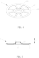
FIG. 4 is a schematic diagram of the three-dimensional structure of the positive current collector plate in the second embodiment of the present application. -
FIG. 5 is a front view ofFIG. 4 . -
FIG. 6 is a cross-sectional view of the cylindrical battery in the second embodiment of the present application. - Specific embodiments of the present application are further described in detail below in conjunction with the accompanying drawings. The following embodiments are used to illustrate the present application, but are not used to limit the scope of the present application.
- The terms "first", "second", "third", "fourth", etc. (if any) in the specification and claims of the present application are used to distinguish similar objects, and are not used to describe a specific order or sequence.
- The orientation terms "up", "down", "left", "right", "front", "back", "top", "bottom", etc. (if any) in the specification and claims of the present application are defined based on the positions of the structures and the positions between the structures in the figures, only for the clarity and convenience of expressing the technical solution. It should be understood that the use of these orientation terms should not limit the scope of the present application.
- As shown in
FIGS. 1 to 3 , the first embodiment of the present application provides a positive current collector plate 1 for connectingpositive tabs 21 and a positive cover plate 3 of a battery. The positive current collector plate 1 is located between thepositive tabs 21 and the positive cover plate 3. The positive current collector plate 1 includes aplate body 11 and anelectrical connection part 12. Theelectrical connection part 12 extends and protrudes from theplate body 11 towards the positive cover plate 3. Theplate body 11 is in contact with thepositive tabs 21, while theelectrical connection part 12 is in contact with the positive cover plate 3. - As shown in
FIGS. 1 and 2 , in one embodiment, theplate body 11 is a disc-shaped structure with hollows and concaves. A throughhole 111 is provided in the central position of theplate body 11, and theelectrical connection part 12 is formed by extending and protruding from the outer edge of the throughhole 111 towards the positive cover plate 3, that is, theelectrical connection part 12 is located in the central position of theplate body 11. - As shown in
FIGS. 1 to 3 , in one embodiment, theelectrical connection part 12 is a flat sheet structure, and the positive cover plate 3 is provided with acentral hole 31. Theelectrical connection part 12 passes through thecentral hole 31 and is then bent to contact the top surface of the positive cover plate 3. - Specifically, in this embodiment, the number of the
electrical connection part 12 is two, and the twoelectrical connection parts 12 are arranged opposite to each other and are respectively provided on two sides of the throughhole 111. Of course, in other embodiments, the number of theelectrical connection part 12 can be one or more. Meanwhile, in this embodiment, theelectrical connection part 12 is a rectangular metal sheet structure. Of course, theelectrical connection part 12 can also have other structures such as quadrilateral (e.g., trapezoid, parallelogram, etc.), triangle, or semicircle, which is not limited here. During assembly, the twoelectrical connection parts 12 extend out of thecentral hole 31 of the positive cover plate 3 and then are respectively bent towards two sides to form bent portions which are in overlapping contact with the top surface of the positive cover plate 3, and then the portions where the bent portions are in overlapping contact with the positive cover plate 3 are welded and fixed. - As shown in
FIG. 3 , in one embodiment, the height of theelectrical connection part 12 protruding out of the positive cover plate 3 is from 0 to 4mm, or from 0 to 2mm. The protruded portion is mainly used to facilitate the welding between theelectrical connection part 12 and the positive cover plate 3. - In another embodiment, the height of the
electrical connection part 12 protruding out of the positive cover plate 3 is from 0 to 1mm. - As shown in
FIGS. 1 and 2 , in one embodiment, the numerical value of the minimum cross-sectional area (unit: mm2) of theelectrical connection part 12 is from 1/8 to 1 or from 1/5 to 1 of the numerical value of 1C current (unit: A). - As shown in
FIG. 3 , in one embodiment, the numerical value of the welding area (unit: mm2) between theelectrical connection part 12 and the positive cover plate 3 is from 1/8 to 1 of the numerical value of 1C current (unit: A), and the numerical value of the contact area (unit: mm2) at the position where theelectrical connection part 12 is connected with theplate body 11 is from 1/8 to 1 of the numerical value of 1C current (unit: A). - Specifically, when the ampere value of the current during battery discharge is equal to the ampere hour value of the battery capacity, it is called 1C discharge. In theory, 1C discharge can fully discharge all the electrical energy of a fully charged battery in one hour. For example, if the battery capacity of a certain battery is 3000mAh (i.e., 3Ah) and a current of 3A is used for discharge, the battery can be fully discharged in one hour. 3A is the 1C current of the battery. Then, the welding area between the
electrical connection part 12 and the positive cover plate 3 in the battery is from 3/8 to 3 mm2, and the contact area at the position where theelectrical connection part 12 is connected with theplate body 11 is from 3/8 to 3 mm2. - In another embodiment, the numerical value of the welding area (unit: mm2) between the
electrical connection part 12 and the positive cover plate 3 is from 1/5 to 1 of the numerical value of 1C current (unit: A), and the numerical value of the contact area (unit: mm2) at the position where theelectrical connection part 12 is connected with theplate body 11 is from 1/5 to 1 of the numerical value of 1C current (unit: A). - As shown in
FIG. 3 , the first embodiment of the present application also provides a cylindrical battery, which includes a jelly roll 2, ahousing 4, and a positive cover plate 3. The cylindrical battery also includes the positive current collector plate 1 mentioned above. The top of thehousing 4 is provided with an opening 41, and the positive cover plate 3 is fixed at the opening 41. The jelly roll 2 is located inside thehousing 4, and the top of the jelly roll 2 is provided with thepositive tabs 21. The positive current collector plate 1 is located between thepositive tabs 21 and the positive cover plate 3. Theplate body 11 is in contact with thepositive tabs 21, and theelectrical connection part 12 is in contact with the positive cover plate 3. - As shown in
FIG. 3 , in one embodiment, the cylindrical battery also includes a negative current collector plate 5. The bottom of the jelly roll 2 is provided withnegative tabs 22, and the negative current collector plate 5 is located inside thehousing 4. Two sides of the negative current collector plate 5 are respectively in contact with thenegative tabs 22 and the inner wall of thehousing 4. - As shown in
FIG. 3 , in one embodiment, both thepositive tabs 21 and thenegative tabs 22 adopt a full tab design. - As shown in
FIG. 3 , in one embodiment, the cylindrical battery also includes aninsulation sealing ring 6, an insulation gasket 7, and an explosion-proof plate 8. Theinsulation sealing ring 6 is arranged around the outer edge of the positive cover plate 3, and theinsulation sealing ring 6 is located between the positive cover plate 3 and the inner wall of thehousing 4. The insulation gasket 7 is arranged on the top surface of the positive current collector plate 1, and the insulation gasket 7 is located between the positive current collector plate 1 and the inner wall of thehousing 4. The explosion-proof plate 8 is sealed and connected to the top surface of the positive cover plate 3. - Specifically, the
housing 4 is a steel housing, thepositive tabs 21 are electrically connected to the positive cover plate 3 through the positive current collector plate 1, and thenegative tabs 22 are electrically connected to thehousing 4 through the negative current collector plate 5. During the assembly process of the battery, the positive current collector plate 1 is separated from thehousing 4 by the insulation gasket 7, and the positive cover plate 3 is separated from thehousing 4 by theinsulation sealing ring 6. Then, the positive cover plate 3 and thehousing 4 are sealed by compressing theinsulation sealing ring 6 through pier sealing after a rolled groove being mechanically formed on thehousing 4. After rolling, the positive current collector plate 1 and the positive cover plate 3 are welded, and finally the explosion-proof plate 8 is welded for sealing. The cylindrical battery greatly improves its conductivity due to the shortened path of current from thepositive tabs 21 to the positive cover plate 3. - As shown in
FIGS. 4 to 6 , the second embodiment of the present application provides a positive current collector plate 1. Theelectrical connection part 12 has a circular cross-section. The positive cover plate 3 is provided with acentral hole 31, and theelectrical connection part 12 is inserted into and extends out of thecentral hole 31. The side wall of theelectrical connection part 12 is in contact with the side wall of thecentral hole 31. During assembly, after theelectrical connection part 12 extends out of thecentral hole 31, the side wall of theelectrical connection part 12 and the side wall of thecentral hole 31 are fixed by welding. - As shown in
FIGS. 4 to 6 , theelectrical connection part 12 has a hollow truncated cone shaped structure with a gradually decreasing diameter in the direction towards the positive cover plate 3. The angle a between the side wall of theelectrical connection part 12 and the vertical direction Y is from 0 to 60° (the angle a is also known as the drawing angle). The truncated cone shaped structure facilitates theelectrical connection part 12 to smoothly pass through thecentral hole 31 of the positive cover plate 3. - As shown in
FIG. 6 , in one embodiment, the height of theelectrical connection part 12 protruding out of the positive cover plate 3 is from 0 to 2mm. The protruded portion is mainly used to facilitate the welding between theelectrical connection part 12 and the positive cover plate 3. - In another embodiment, the height of the
electrical connection part 12 protruding out of the positive cover plate 3 is from 0 to 1mm. - As shown in
FIG. 6 , in one embodiment, the numerical value of the welding area (unit: mm2) between theelectrical connection part 12 and the positive cover plate 3 is from 1/8 to 1 of the numerical value of 1C current (unit: A), and the numerical value of the contact area (unit: mm2) at the position where theelectrical connection part 12 is connected with theplate body 11 is from 1/8 to 1 of the numerical value of 1C current (unit: A). - In another embodiment, the numerical value of the welding area (unit: mm2) between the
electrical connection part 12 and the positive cover plate 3 is from 1/5 to 1 of the numerical value of 1C current (unit: A), and the numerical value of the contact area (unit: mm2) at the position where theelectrical connection part 12 is connected with theplate body 11 is from 1/5 to 1 of the numerical value of 1C current (unit: A). - As shown in
FIGS. 4 and 5 , in one embodiment, the numerical value of the minimum cross-sectional area (unit: mm2) of theelectrical connection part 12 is from 1/8 to 1 or from 1/5 to 1 of the numerical value of 1C current (unit: A). - As shown in
FIG. 6 , the second embodiment of the present application also provides a cylindrical battery using the positive current collector plate 1 mentioned above. The other structures of the cylindrical battery are the same as those of the first embodiment, and will not be further described here. - In the positive current collector plate 1 provided in the embodiments of the present application, the
electrical connection part 12 is directly connected to theplate body 11 and the positive cover plate 3, and theplate body 11 is directly in contact with thepositive tabs 21, thereby shortening the path of current from the positive cover plate 3 to thepositive tabs 21, greatly reducing the internal resistance of the positive current collector plate 1, improving the conductivity of the battery, and reducing the heat production of the positive current collector plate 1. Further, theelectrical connector 12 on the positive current collector plate 1 does not need to be bent in a "Z" shape, which is not prone to cracks, and it is also convenient to be welded and fixed with the positive cover plate 3, which has high assembly efficiency and is suitable for industrial production. Therefore, the positive current collector plate 1 provided in the embodiments of the present application solves the problems of high heat production, bending of electrical connectors during assembly, easy cracking, low assembly efficiency, and poor battery conductivity in traditional cylindrical full tab batteries. - The above is only specific embodiments of the present application, but the scope of protection of the present application is not limited to this. Any person skilled in the technical field can easily think of changes or replacements within the technical scope disclosed by the present application, which should also be covered by the scope of protection of the present application. Therefore, the scope of protection of the present application shall be defined by the appended claims.
Claims (10)
- A positive current collector plate, wherein the positive current collector plate (1) is located between positive tabs (21) and a positive cover plate (3), the positive current collector plate (1) comprises a plate body (11) and an electrical connection part (12), the electrical connection part (12) extends and protrudes from the plate body (11) towards the positive cover plate (3), the plate body (11) is in contact with the positive tabs (21), and the electrical connection part (12) is in contact with the positive cover plate (3).
- The positive current collector plate as claimed in claim 1, wherein a through hole (111) is provided in the central position of the plate body (11), the electrical connection part (12) is formed by extending and protruding from an outer edge of the through hole (111) towards the positive cover plate (3).
- The positive current collector plate as claimed in claim 1, wherein the electrical connection part (12) is a flat sheet structure, the positive cover plate (3) is provided with a central hole (31), the electrical connection part (12) passes through the central hole (31) and is bent to contact a top surface of the positive cover plate (3).
- The positive current collector plate as claimed in claim 1, wherein the electrical connection part (12) has a circular cross-section, the positive cover plate (3) is provided with a central hole (31), the electrical connection part (12) is inserted into and extends out of the central hole (31), and a side wall of the electrical connection part (12) is in contact with a side wall of the central hole (31).
- The positive current collector plate as claimed in claim 4, wherein the electrical connection part (12) is a hollow truncated cone shaped structure with a gradually decreasing diameter in a direction towards the positive cover plate (3), and the angle (a) between the side wall of the electrical connection part (12) and the vertical direction (Y) is from 0 to 60°.
- The positive current collector plate as claimed in any one of claims 3 to 5, wherein a height of the electrical connection part (12) protruding out of the positive cover plate (3) is from 0 to 2mm, a numerical value of minimum cross-sectional area (unit: mm2) of the electrical connection part (12) is from 1/8 to 1 or from 1/5 to 1 of a numerical value of 1C current (unit: A).
- The positive current collector plate as claimed in any one of claims 1 to 5, wherein a numerical value of welding area (unit: mm2) between the electrical connection part (12) and the positive cover plate (3) is from 1/8 to 1 or from 1/5 to 1 of a numerical value of 1C current (unit: A); a numerical value of contact area (unit: mm2) at the position where the electrical connection part (12) is connected with the plate body (11) is from 1/8 to 1 or from 1/5 to 1 of a numerical value of 1C current (unit: A).
- A cylindrical battery, comprising a jelly roll (2), a housing (4), and a positive cover plate (3), wherein the cylindrical battery further comprises the positive current collector plate (1) as claimed in any one of claims 1 to 7, the top of the housing (4) is provided with an opening (41), the positive cover plate (3) is fixed at the opening (41), the jelly roll (2) is located inside the housing (4), the top of the jelly roll (2) is provided with the positive tabs (21), the positive current collector plate (1) is located between the positive tabs (21) and the positive cover plate (3), the plate body (11) is in contact with the positive tabs (21), and the electrical connection part (12) is in contact with the positive cover plate (3).
- The cylindrical battery as claimed in claim 8, wherein the cylindrical battery further comprises a negative current collector plate (5), the bottom of the jelly roll (2) is provided with negative tabs (22), the negative current collector plate (5) is located inside the housing (4), and two sides of the negative current collector plate (5) are respectively in contact with the negative tabs (22) and an inner wall of the housing (4).
- The cylindrical battery as claimed in claim 8, wherein the cylindrical battery further comprises an insulation sealing ring (6), an insulation gasket (7), and an explosion-proof plate (8), the insulation sealing ring (6) is arranged around the outer edge of the positive cover plate (3), and the insulation sealing ring (6) is located between the positive cover plate (3) and the inner wall of the housing (4), the insulation gasket (7) is arranged on a top surface of the positive current collector plate (1), and the insulation gasket (7) is located between the positive current collector plate (1) and the inner wall of the housing (4), the explosion-proof plate (8) is sealed and connected to the top surface of the positive cover plate (3).
Applications Claiming Priority (1)
| Application Number | Priority Date | Filing Date | Title |
|---|---|---|---|
| PCT/CN2021/094137 WO2022241615A1 (en) | 2021-05-17 | 2021-05-17 | Positive electrode current collector disc and cylindrical battery |
Publications (2)
| Publication Number | Publication Date |
|---|---|
| EP4343933A1 true EP4343933A1 (en) | 2024-03-27 |
| EP4343933A4 EP4343933A4 (en) | 2025-08-13 |
Family
ID=84141000
Family Applications (1)
| Application Number | Title | Priority Date | Filing Date |
|---|---|---|---|
| EP21940072.8A Pending EP4343933A4 (en) | 2021-05-17 | 2021-05-17 | POSITIVE ELECTRODE CURRENT COLLECTOR DISC AND CYLINDRICAL BATTERY |
Country Status (4)
| Country | Link |
|---|---|
| US (1) | US20240243300A1 (en) |
| EP (1) | EP4343933A4 (en) |
| CN (1) | CN117355982A (en) |
| WO (1) | WO2022241615A1 (en) |
Families Citing this family (8)
| Publication number | Priority date | Publication date | Assignee | Title |
|---|---|---|---|---|
| CN114937854B (en) * | 2022-05-24 | 2025-12-09 | 微宏动力系统(湖州)有限公司 | Battery pack, battery and electric vehicle |
| CN116487830A (en) * | 2023-03-17 | 2023-07-25 | 蓝京新能源(嘉兴)有限公司 | Cylindrical aluminum battery and preparation process thereof |
| CN116544572A (en) * | 2023-03-30 | 2023-08-04 | 厦门海辰储能科技股份有限公司 | End cover assembly, energy storage device and electric equipment |
| CN116487785B (en) * | 2023-04-28 | 2025-08-22 | 厦门海辰储能科技股份有限公司 | End cover assembly, energy storage device and electrical equipment |
| CN116505087B (en) * | 2023-06-26 | 2023-09-26 | 宁德时代新能源科技股份有限公司 | Battery cells, batteries and electrical devices |
| CN116845495A (en) * | 2023-07-03 | 2023-10-03 | 蜂巢能源科技股份有限公司 | Battery cell |
| WO2025065825A1 (en) * | 2023-09-28 | 2025-04-03 | 重庆太蓝新能源有限公司 | Battery unit and manufacturing method therefor, annular battery, battery module, and electrical device |
| CN222705562U (en) * | 2024-06-07 | 2025-04-01 | 深圳市比克动力电池有限公司 | A safe cylindrical battery |
Family Cites Families (10)
| Publication number | Priority date | Publication date | Assignee | Title |
|---|---|---|---|---|
| JP2004296341A (en) * | 2003-03-27 | 2004-10-21 | Sanyo Electric Co Ltd | Secondary battery and method of manufacturing the same |
| CN204885267U (en) * | 2015-07-22 | 2015-12-16 | 朝阳立塬新能源有限公司 | Low internal resistance energy storage device is drawn forth to bi -polar |
| EP3306699B1 (en) * | 2016-10-10 | 2018-08-22 | VARTA Microbattery GmbH | Lithium cell |
| US10714732B2 (en) * | 2017-01-30 | 2020-07-14 | Fdk Corporation | Current collecting lead and production method for secondary battery including current collecting lead |
| CN207947342U (en) * | 2018-03-13 | 2018-10-09 | 苏州安靠电源有限公司 | Negative pole currect collecting component and the cylindrical battery for configuring the component |
| CN208284546U (en) * | 2018-04-20 | 2018-12-25 | 苏州安靠电源有限公司 | Cylindrical battery and its electrode current collecting component |
| CN208797120U (en) * | 2018-07-04 | 2019-04-26 | 苏州安靠电源有限公司 | The end face weld battery of excellent heat radiation performance |
| CN209328958U (en) * | 2018-12-24 | 2019-08-30 | 苏州安靠电源有限公司 | A kind of battery cap and cylindrical battery |
| CN209328960U (en) * | 2018-12-29 | 2019-08-30 | 苏州安靠电源有限公司 | Battery cap and cylindrical battery |
| CN210073928U (en) * | 2019-04-10 | 2020-02-14 | 苏州安靠电源有限公司 | Cylindrical battery and battery cap thereof |
-
2021
- 2021-05-17 WO PCT/CN2021/094137 patent/WO2022241615A1/en not_active Ceased
- 2021-05-17 CN CN202180098338.3A patent/CN117355982A/en active Pending
- 2021-05-17 US US18/561,743 patent/US20240243300A1/en active Pending
- 2021-05-17 EP EP21940072.8A patent/EP4343933A4/en active Pending
Also Published As
| Publication number | Publication date |
|---|---|
| US20240243300A1 (en) | 2024-07-18 |
| WO2022241615A1 (en) | 2022-11-24 |
| EP4343933A4 (en) | 2025-08-13 |
| CN117355982A (en) | 2024-01-05 |
Similar Documents
| Publication | Publication Date | Title |
|---|---|---|
| EP4343933A1 (en) | Positive electrode current collector disc and cylindrical battery | |
| CN204834764U (en) | Cylindrical high magnification lithium ion battery of edge weld | |
| CN114937854A (en) | Battery pack, battery and electric vehicle | |
| CN101908643B (en) | Power lithium ion battery and production method thereof | |
| CN101771165A (en) | Cylindrical lithium-ion power battery and preparation method thereof | |
| CN202839828U (en) | Power battery | |
| CN112993491A (en) | Lithium battery, battery cell and assembly method | |
| US20230299396A1 (en) | Battery assembly and preparation method, battery and electric vehicle | |
| CN115799657B (en) | Cylindrical battery and manufacturing process thereof | |
| CN219371103U (en) | Cylindrical battery and battery pack | |
| CN218867347U (en) | A battery cell pole group and a battery cell | |
| CN216311911U (en) | Big cylindrical battery structure of full utmost point ear | |
| CN114614204A (en) | High-capacity battery pack with conductive component | |
| CN204966576U (en) | Bipolar ear polymer high magnification battery | |
| CN221407578U (en) | Battery cell assembly and battery | |
| CN221080286U (en) | Multipolar ear battery | |
| CN219086204U (en) | Cylindrical battery | |
| CN202395088U (en) | Cylindrical lithium ion battery | |
| JP2013543225A (en) | Conductive connection structure of secondary battery cell | |
| CN223539627U (en) | Winding type battery cell, battery monomer, battery and electric equipment | |
| CN219086094U (en) | Cylindrical battery | |
| CN218005175U (en) | A kind of battery and battery module | |
| CN223712797U (en) | A multi-tab electrode structure for lithium-ion batteries | |
| CN219658762U (en) | An anti-short circuit cell and power battery | |
| CN222300808U (en) | Sodium-electricity steel shell large cylinder high-multiplying power battery |
Legal Events
| Date | Code | Title | Description |
|---|---|---|---|
| STAA | Information on the status of an ep patent application or granted ep patent |
Free format text: STATUS: THE INTERNATIONAL PUBLICATION HAS BEEN MADE |
|
| PUAI | Public reference made under article 153(3) epc to a published international application that has entered the european phase |
Free format text: ORIGINAL CODE: 0009012 |
|
| STAA | Information on the status of an ep patent application or granted ep patent |
Free format text: STATUS: REQUEST FOR EXAMINATION WAS MADE |
|
| 17P | Request for examination filed |
Effective date: 20231120 |
|
| AK | Designated contracting states |
Kind code of ref document: A1 Designated state(s): AL AT BE BG CH CY CZ DE DK EE ES FI FR GB GR HR HU IE IS IT LI LT LU LV MC MK MT NL NO PL PT RO RS SE SI SK SM TR |
|
| DAV | Request for validation of the european patent (deleted) | ||
| DAX | Request for extension of the european patent (deleted) | ||
| A4 | Supplementary search report drawn up and despatched |
Effective date: 20250711 |
|
| RIC1 | Information provided on ipc code assigned before grant |
Ipc: H01M 50/147 20210101AFI20250707BHEP Ipc: H01M 50/172 20210101ALI20250707BHEP Ipc: H01M 50/107 20210101ALI20250707BHEP Ipc: H01M 50/531 20210101ALI20250707BHEP Ipc: H01M 50/533 20210101ALI20250707BHEP Ipc: H01M 50/536 20210101ALI20250707BHEP Ipc: H01M 50/538 20210101ALI20250707BHEP Ipc: H01M 50/152 20210101ALI20250707BHEP Ipc: H01M 50/559 20210101ALI20250707BHEP Ipc: H01M 10/04 20060101ALI20250707BHEP |