EP4343929A1 - Fire-spread prevention type cell unit, method for manufacturing same, and battery - Google Patents
Fire-spread prevention type cell unit, method for manufacturing same, and battery Download PDFInfo
- Publication number
- EP4343929A1 EP4343929A1 EP21956003.4A EP21956003A EP4343929A1 EP 4343929 A1 EP4343929 A1 EP 4343929A1 EP 21956003 A EP21956003 A EP 21956003A EP 4343929 A1 EP4343929 A1 EP 4343929A1
- Authority
- EP
- European Patent Office
- Prior art keywords
- fire
- spread prevention
- sheet
- battery
- prevention sheet
- Prior art date
- Legal status (The legal status is an assumption and is not a legal conclusion. Google has not performed a legal analysis and makes no representation as to the accuracy of the status listed.)
- Pending
Links
- 230000002265 prevention Effects 0.000 title claims abstract description 135
- 238000000034 method Methods 0.000 title claims abstract description 23
- 238000004519 manufacturing process Methods 0.000 title claims abstract description 19
- 239000011148 porous material Substances 0.000 claims abstract description 46
- 239000000203 mixture Substances 0.000 claims description 17
- 239000000463 material Substances 0.000 claims description 12
- 229920002379 silicone rubber Polymers 0.000 claims description 11
- 239000004945 silicone rubber Substances 0.000 claims description 11
- 238000005187 foaming Methods 0.000 claims description 8
- 238000007493 shaping process Methods 0.000 claims description 8
- 239000003063 flame retardant Substances 0.000 claims description 5
- 230000001939 inductive effect Effects 0.000 claims description 3
- 230000005489 elastic deformation Effects 0.000 abstract description 6
- 230000007774 longterm Effects 0.000 abstract description 5
- 238000013021 overheating Methods 0.000 abstract description 4
- 230000004044 response Effects 0.000 abstract description 3
- 238000000465 moulding Methods 0.000 description 22
- 230000006835 compression Effects 0.000 description 21
- 238000007906 compression Methods 0.000 description 21
- 229920001971 elastomer Polymers 0.000 description 9
- 230000003746 surface roughness Effects 0.000 description 9
- 239000005060 rubber Substances 0.000 description 8
- 238000009413 insulation Methods 0.000 description 5
- OZAIFHULBGXAKX-UHFFFAOYSA-N 2-(2-cyanopropan-2-yldiazenyl)-2-methylpropanenitrile Chemical compound N#CC(C)(C)N=NC(C)(C)C#N OZAIFHULBGXAKX-UHFFFAOYSA-N 0.000 description 4
- 239000000853 adhesive Substances 0.000 description 4
- 230000001070 adhesive effect Effects 0.000 description 4
- 239000004088 foaming agent Substances 0.000 description 4
- 238000010068 moulding (rubber) Methods 0.000 description 4
- BASFCYQUMIYNBI-UHFFFAOYSA-N platinum Chemical compound [Pt] BASFCYQUMIYNBI-UHFFFAOYSA-N 0.000 description 4
- 239000002826 coolant Substances 0.000 description 3
- 238000005259 measurement Methods 0.000 description 3
- 239000011347 resin Substances 0.000 description 3
- 229920005989 resin Polymers 0.000 description 3
- 230000000391 smoking effect Effects 0.000 description 3
- 238000012546 transfer Methods 0.000 description 3
- 239000004156 Azodicarbonamide Substances 0.000 description 2
- KAKZBPTYRLMSJV-UHFFFAOYSA-N Butadiene Chemical compound C=CC=C KAKZBPTYRLMSJV-UHFFFAOYSA-N 0.000 description 2
- OKTJSMMVPCPJKN-UHFFFAOYSA-N Carbon Chemical compound [C] OKTJSMMVPCPJKN-UHFFFAOYSA-N 0.000 description 2
- 229920000459 Nitrile rubber Polymers 0.000 description 2
- PPBRXRYQALVLMV-UHFFFAOYSA-N Styrene Chemical compound C=CC1=CC=CC=C1 PPBRXRYQALVLMV-UHFFFAOYSA-N 0.000 description 2
- XOZUGNYVDXMRKW-AATRIKPKSA-N azodicarbonamide Chemical compound NC(=O)\N=N\C(N)=O XOZUGNYVDXMRKW-AATRIKPKSA-N 0.000 description 2
- 235000019399 azodicarbonamide Nutrition 0.000 description 2
- 238000001816 cooling Methods 0.000 description 2
- 238000010586 diagram Methods 0.000 description 2
- 239000006260 foam Substances 0.000 description 2
- 230000002401 inhibitory effect Effects 0.000 description 2
- -1 phosphorus compound Chemical class 0.000 description 2
- 229910052697 platinum Inorganic materials 0.000 description 2
- 238000012545 processing Methods 0.000 description 2
- 238000011084 recovery Methods 0.000 description 2
- 239000012508 resin bead Substances 0.000 description 2
- 125000006850 spacer group Chemical group 0.000 description 2
- 238000012360 testing method Methods 0.000 description 2
- 229920002943 EPDM rubber Polymers 0.000 description 1
- JOYRKODLDBILNP-UHFFFAOYSA-N Ethyl urethane Chemical compound CCOC(N)=O JOYRKODLDBILNP-UHFFFAOYSA-N 0.000 description 1
- 229920000181 Ethylene propylene rubber Polymers 0.000 description 1
- PXGOKWXKJXAPGV-UHFFFAOYSA-N Fluorine Chemical compound FF PXGOKWXKJXAPGV-UHFFFAOYSA-N 0.000 description 1
- 244000043261 Hevea brasiliensis Species 0.000 description 1
- HBBGRARXTFLTSG-UHFFFAOYSA-N Lithium ion Chemical compound [Li+] HBBGRARXTFLTSG-UHFFFAOYSA-N 0.000 description 1
- 229920006311 Urethane elastomer Polymers 0.000 description 1
- 150000001336 alkenes Chemical class 0.000 description 1
- 229910052782 aluminium Inorganic materials 0.000 description 1
- XAGFODPZIPBFFR-UHFFFAOYSA-N aluminium Chemical compound [Al] XAGFODPZIPBFFR-UHFFFAOYSA-N 0.000 description 1
- WNROFYMDJYEPJX-UHFFFAOYSA-K aluminium hydroxide Chemical compound [OH-].[OH-].[OH-].[Al+3] WNROFYMDJYEPJX-UHFFFAOYSA-K 0.000 description 1
- 229910003481 amorphous carbon Inorganic materials 0.000 description 1
- 238000005422 blasting Methods 0.000 description 1
- 239000007767 bonding agent Substances 0.000 description 1
- 229910052799 carbon Inorganic materials 0.000 description 1
- 239000002131 composite material Substances 0.000 description 1
- 239000000498 cooling water Substances 0.000 description 1
- 238000011161 development Methods 0.000 description 1
- 230000000694 effects Effects 0.000 description 1
- 239000000806 elastomer Substances 0.000 description 1
- 150000002148 esters Chemical class 0.000 description 1
- 238000004880 explosion Methods 0.000 description 1
- 239000010419 fine particle Substances 0.000 description 1
- 229910052731 fluorine Inorganic materials 0.000 description 1
- 239000011737 fluorine Substances 0.000 description 1
- 229910002804 graphite Inorganic materials 0.000 description 1
- 239000010439 graphite Substances 0.000 description 1
- 230000005484 gravity Effects 0.000 description 1
- 150000004820 halides Chemical class 0.000 description 1
- 150000002484 inorganic compounds Chemical class 0.000 description 1
- 229910010272 inorganic material Inorganic materials 0.000 description 1
- 229920003049 isoprene rubber Polymers 0.000 description 1
- 239000007788 liquid Substances 0.000 description 1
- 229910001416 lithium ion Inorganic materials 0.000 description 1
- VTHJTEIRLNZDEV-UHFFFAOYSA-L magnesium dihydroxide Chemical compound [OH-].[OH-].[Mg+2] VTHJTEIRLNZDEV-UHFFFAOYSA-L 0.000 description 1
- 229910001862 magnesium hydroxide Inorganic materials 0.000 description 1
- 239000000347 magnesium hydroxide Substances 0.000 description 1
- 229910052751 metal Inorganic materials 0.000 description 1
- 239000002184 metal Substances 0.000 description 1
- 229920003052 natural elastomer Polymers 0.000 description 1
- 229920001194 natural rubber Polymers 0.000 description 1
- JRZJOMJEPLMPRA-UHFFFAOYSA-N olefin Natural products CCCCCCCC=C JRZJOMJEPLMPRA-UHFFFAOYSA-N 0.000 description 1
- 229910052698 phosphorus Inorganic materials 0.000 description 1
- 239000011574 phosphorus Substances 0.000 description 1
- 238000005498 polishing Methods 0.000 description 1
- 229920000139 polyethylene terephthalate Polymers 0.000 description 1
- 239000005020 polyethylene terephthalate Substances 0.000 description 1
- 230000002062 proliferating effect Effects 0.000 description 1
- 239000003507 refrigerant Substances 0.000 description 1
- 238000003860 storage Methods 0.000 description 1
- 229920003048 styrene butadiene rubber Polymers 0.000 description 1
- 229920002725 thermoplastic elastomer Polymers 0.000 description 1
- 229920001187 thermosetting polymer Polymers 0.000 description 1
Images

Classifications
-
- H—ELECTRICITY
- H01—ELECTRIC ELEMENTS
- H01M—PROCESSES OR MEANS, e.g. BATTERIES, FOR THE DIRECT CONVERSION OF CHEMICAL ENERGY INTO ELECTRICAL ENERGY
- H01M10/00—Secondary cells; Manufacture thereof
- H01M10/60—Heating or cooling; Temperature control
- H01M10/65—Means for temperature control structurally associated with the cells
- H01M10/658—Means for temperature control structurally associated with the cells by thermal insulation or shielding
-
- H—ELECTRICITY
- H01—ELECTRIC ELEMENTS
- H01M—PROCESSES OR MEANS, e.g. BATTERIES, FOR THE DIRECT CONVERSION OF CHEMICAL ENERGY INTO ELECTRICAL ENERGY
- H01M50/00—Constructional details or processes of manufacture of the non-active parts of electrochemical cells other than fuel cells, e.g. hybrid cells
- H01M50/30—Arrangements for facilitating escape of gases
- H01M50/383—Flame arresting or ignition-preventing means
-
- H—ELECTRICITY
- H01—ELECTRIC ELEMENTS
- H01M—PROCESSES OR MEANS, e.g. BATTERIES, FOR THE DIRECT CONVERSION OF CHEMICAL ENERGY INTO ELECTRICAL ENERGY
- H01M50/00—Constructional details or processes of manufacture of the non-active parts of electrochemical cells other than fuel cells, e.g. hybrid cells
- H01M50/20—Mountings; Secondary casings or frames; Racks, modules or packs; Suspension devices; Shock absorbers; Transport or carrying devices; Holders
- H01M50/204—Racks, modules or packs for multiple batteries or multiple cells
-
- H—ELECTRICITY
- H01—ELECTRIC ELEMENTS
- H01M—PROCESSES OR MEANS, e.g. BATTERIES, FOR THE DIRECT CONVERSION OF CHEMICAL ENERGY INTO ELECTRICAL ENERGY
- H01M50/00—Constructional details or processes of manufacture of the non-active parts of electrochemical cells other than fuel cells, e.g. hybrid cells
- H01M50/20—Mountings; Secondary casings or frames; Racks, modules or packs; Suspension devices; Shock absorbers; Transport or carrying devices; Holders
- H01M50/204—Racks, modules or packs for multiple batteries or multiple cells
- H01M50/207—Racks, modules or packs for multiple batteries or multiple cells characterised by their shape
- H01M50/209—Racks, modules or packs for multiple batteries or multiple cells characterised by their shape adapted for prismatic or rectangular cells
-
- H—ELECTRICITY
- H01—ELECTRIC ELEMENTS
- H01M—PROCESSES OR MEANS, e.g. BATTERIES, FOR THE DIRECT CONVERSION OF CHEMICAL ENERGY INTO ELECTRICAL ENERGY
- H01M50/00—Constructional details or processes of manufacture of the non-active parts of electrochemical cells other than fuel cells, e.g. hybrid cells
- H01M50/20—Mountings; Secondary casings or frames; Racks, modules or packs; Suspension devices; Shock absorbers; Transport or carrying devices; Holders
- H01M50/233—Mountings; Secondary casings or frames; Racks, modules or packs; Suspension devices; Shock absorbers; Transport or carrying devices; Holders characterised by physical properties of casings or racks, e.g. dimensions
- H01M50/24—Mountings; Secondary casings or frames; Racks, modules or packs; Suspension devices; Shock absorbers; Transport or carrying devices; Holders characterised by physical properties of casings or racks, e.g. dimensions adapted for protecting batteries from their environment, e.g. from corrosion
-
- H—ELECTRICITY
- H01—ELECTRIC ELEMENTS
- H01M—PROCESSES OR MEANS, e.g. BATTERIES, FOR THE DIRECT CONVERSION OF CHEMICAL ENERGY INTO ELECTRICAL ENERGY
- H01M50/00—Constructional details or processes of manufacture of the non-active parts of electrochemical cells other than fuel cells, e.g. hybrid cells
- H01M50/20—Mountings; Secondary casings or frames; Racks, modules or packs; Suspension devices; Shock absorbers; Transport or carrying devices; Holders
- H01M50/289—Mountings; Secondary casings or frames; Racks, modules or packs; Suspension devices; Shock absorbers; Transport or carrying devices; Holders characterised by spacing elements or positioning means within frames, racks or packs
- H01M50/291—Mountings; Secondary casings or frames; Racks, modules or packs; Suspension devices; Shock absorbers; Transport or carrying devices; Holders characterised by spacing elements or positioning means within frames, racks or packs characterised by their shape
-
- H—ELECTRICITY
- H01—ELECTRIC ELEMENTS
- H01M—PROCESSES OR MEANS, e.g. BATTERIES, FOR THE DIRECT CONVERSION OF CHEMICAL ENERGY INTO ELECTRICAL ENERGY
- H01M50/00—Constructional details or processes of manufacture of the non-active parts of electrochemical cells other than fuel cells, e.g. hybrid cells
- H01M50/20—Mountings; Secondary casings or frames; Racks, modules or packs; Suspension devices; Shock absorbers; Transport or carrying devices; Holders
- H01M50/289—Mountings; Secondary casings or frames; Racks, modules or packs; Suspension devices; Shock absorbers; Transport or carrying devices; Holders characterised by spacing elements or positioning means within frames, racks or packs
- H01M50/293—Mountings; Secondary casings or frames; Racks, modules or packs; Suspension devices; Shock absorbers; Transport or carrying devices; Holders characterised by spacing elements or positioning means within frames, racks or packs characterised by the material
-
- Y—GENERAL TAGGING OF NEW TECHNOLOGICAL DEVELOPMENTS; GENERAL TAGGING OF CROSS-SECTIONAL TECHNOLOGIES SPANNING OVER SEVERAL SECTIONS OF THE IPC; TECHNICAL SUBJECTS COVERED BY FORMER USPC CROSS-REFERENCE ART COLLECTIONS [XRACs] AND DIGESTS
- Y02—TECHNOLOGIES OR APPLICATIONS FOR MITIGATION OR ADAPTATION AGAINST CLIMATE CHANGE
- Y02E—REDUCTION OF GREENHOUSE GAS [GHG] EMISSIONS, RELATED TO ENERGY GENERATION, TRANSMISSION OR DISTRIBUTION
- Y02E60/00—Enabling technologies; Technologies with a potential or indirect contribution to GHG emissions mitigation
- Y02E60/10—Energy storage using batteries
Definitions
- the present invention relates to a fire-spread prevention type cell unit having a battery cell with a fire-spread prevention sheet, a method for manufacturing the same, and a battery including the fire-spread prevention cell unit.
- Patent Literature 1 Japanese Patent Laid-Open No. 2018-206604
- a fire-spread prevention sheet desirably has low hardness and is easily deformable because of the need to reduce damage to the sheet even if the battery cells expand due to overheating.
- a fire-spread prevention sheet also preferably contains air to improve the thermal insulation of the sheet.
- the inventor considered providing a porous rubber sheet on the sides of the battery cells and inserting the sheet between the battery cells.
- the inventor developed the porous rubber sheet to maintain the porous state of the sheet by enabling long-term elastic deformation even after repeated compression and release of the sheet.
- the present invention also contributes to achieving the applicant's sustainable development goal to "ensure access to affordable, reliable, sustainable and modern energy for all".
- the present invention has been made in light of the above problems, and an objective thereof is to provide a fire-spread prevention type cell unit having a battery cell with a fire-spread prevention sheet that easily deforms in response to overheating and expansion of battery cells and maintains the porosity of the sheet by enabling long-term elastic deformation, a method for manufacturing the same, and a battery.
- a fire-spread prevention type cell unit having a battery cell with a fire-spread prevention sheet that easily deforms in response to overheating and expansion of battery cells and maintains the porosity of the sheet by enabling long-term elastic deformation, a method for manufacturing the same, and a battery can be provided.
- 1...fire-spread prevention type cell unit 10...fire-spread prevention sheet, 11...application surface, 12...outer surface, 15...pore, 20...battery cell, 25...plate, 26...curable composition, 27...cured body, 30...battery.
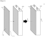
- Figure 1 illustrates a perspective view for explaining a configuration of a fire-spread prevention type cell unit of the embodiment of the invention.
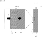
- Figure 2 illustrates an A-A cross section and an enlarged view of portion B of the fire-spread prevention type cell unit in Figure 1 .
- the fire-spread prevention type cell unit 1 of the embodiment includes battery cells 20 and fire-spread prevention sheets 10 applied to the side located in the arrangement direction of the battery cells 20. More specifically, the fire-spread prevention type cell unit 1 is the unification of the battery cells 20 and the fire-spread prevention sheets 10 applied to at least one of the two sides in the direction of arranging the battery cells 20.
- the fire-spread prevention sheet 10 is disposed between multiple battery cells 20 inside a battery and can prevent fire-spread by inhibiting heat transfer to another battery cell 20 when a battery cell 20 overheats.
- the fire-spread prevention sheet 10 is used by applying the broadest surface thereof to the battery cell 20.
- a single configuration of the fire-spread prevention sheet 10 applied to the battery cell 20 is referred to as the fire-spread prevention type cell unit 1.
- the fire-spread prevention sheet 10 adheres to the battery cell 20 and can be applied without an intermediary layer such as a bonding agent.
- the thickness of the fire-spread prevention sheet 10 is not particularly restricted, but is preferably 1-20 mm, more preferably 2-8 mm.
- the adhesion of an application surface 11 to the battery cell 20 is preferably higher than the adhesion of an outer surface 12 located on the opposite side from the application surface 11 in the thickness direction of the fire-spread prevention sheet 10.
- the application surface 11 for applying the fire-spread prevention sheet 10 to the battery cell 20 is a highly smooth surface that can adhere with little or no air intervening state between itself and the broadest surface (side) of the battery cell 20.
- the outer surface 12 is a less smooth surface than the application surface 11.
- the maximum height (Sz) based on "ISO 25178: Surface texture” is preferably greater for the outer surface 12 than the application surface 11.
- the roughness of the application surface 11 and outer surface 12 each can be obtained easily by transferring the roughness of the inner surface of the mold or a resin sheet placed inside the mold.
- a treatment such as blasting to impinge fine particles on the surface may be performed.
- Increasing the surface roughness of the outer surface 12 compared to the application surface 11 in this way facilitates easy loading or withdrawal of one fire-spread prevention type cell unit 1 at a time into or out of the battery enclosure from among multiple fire-spread prevention type cell units 1.
- fire-spread prevention type cell unit 1 does not readily adhere to an adjacent fire-spread prevention type cell unit 1.
- multiple fire-spread prevention type cell units 1 inside a battery are often compressed from the outside in the arrangement direction of the fire-spread prevention type cell units 1 after being loaded into the battery. Even in such cases, a large surface roughness of the outer surface 12 can reduce situations where the fire-spread prevention type cell units 1 stick to each other.
- a smooth application surface 11 can increase adhesive force between the fire-spread prevention sheet 10 and the side of the battery cell 20, allowing for easy loading or withdrawal of one fire-spread prevention type cell unit 1 at a time into or out of the battery.
- the means of making the outer surface 12 less adhesive than the application surface 11 is not limited to differentiating the surface roughness described above, and may be other means.
- the other means may be, for example, forming the fire-spread prevention sheet 10 with two layers of sheets, with the sheet on the outer surface 12 side having greater hardness than the sheet on the application surface 11 side.
- the fire-spread prevention sheet 10 is substantially the same size as the broadest surface (side) of the battery cell 20, but may also be larger or smaller than the side. However, to enhance fire-spread prevention, the fire-spread prevention sheet 10 is preferably the same size or larger than the side of the battery cell 20.
- the fire-spread prevention sheet 10 is a porous sponge sheet.
- the sponge sheet has pores 15 that are preferably 40-95% by volume, more preferably 60-90% by volume, of the total volume of the sheet. Air inside the pores 15 of the sponge sheet provides excellent thermal insulation to the fire-spread prevention sheet 10.
- the fire-spread prevention sheet 10 thus contributes to low thermal conductivity between neighboring battery cells 20.
- the pores 15 have an elongated, that is, anisotropic shape, and the lengthwise direction of the pores 15 is oriented in the thickness direction of the fire-spread prevention sheet 10.
- the lengthwise direction of the pores 15 is substantially parallel (0° ⁇ 5°) to the thickness direction of the fire-spread prevention sheet 10.
- some of the multiple pores 15 may have a shape other than elongated, or pores 15 may exist which have an elongated shape but for which the lengthwise direction is not parallel to the thickness direction. At least 50%, preferably at least 70%, more preferably at least 90% of the total number of pores 15 may have an elongated shape and may be oriented with the lengthwise direction substantially parallel to the thickness direction of the fire-spread prevention sheet 10.
- the elongated pores 15 are oriented with the lengthwise direction of the pores 15 pointing in the thickness direction of the sheet.
- the fire-spread prevention sheet 10 when the fire-spread prevention sheet 10 is compressed in the thickness direction thereof (that is, in Figure 2 , when the fire-spread prevention sheet 10 is subjected to force in direction of arrows F from both sides in the thickness direction), the fire-spread prevention sheet 10 elastically deforms and reduces in thickness, and elastically deforms to the original thickness when the force from arrows F is released. Therefore, the pores 15 can maintain the original shape or a shape close thereto. In this way, the fire-spread prevention sheet 10 can maintain porosity even after repeated compression and release of the fire-spread prevention sheet 10. Accordingly, high thermal insulation of the fire-spread prevention sheet 10 can also be maintained.
- the fire-spread prevention sheet 10 is formed mainly from resin or rubber, preferably rubber.
- the rubber includes, for example, a thermosetting elastomer such as silicone rubber, urethane rubber, isoprene rubber, ethylene propylene rubber, natural rubber, ethylene propylene diene rubber, nitrile rubber (NBR), or styrene butadiene rubber (SBR); a thermoplastic elastomer such as urethane, ester, styrene, olefin, butadiene, or fluorine, or a composite thereof.
- silicone rubber with relatively high heat resistance is more suitable.
- the fire-spread prevention sheet 10 preferably contains silicone rubber as a main material.
- the fire-spread prevention sheet 10 more preferably is a porous silicone rubber sponge sheet. Note that in this application, "mainly" or “main material” is interpreted to exceed 50% by mass of the total materials.
- the fire-spread prevention sheet 10 preferably contains a fire retardant material to further enhance fire-spread prevention ability.
- the fire retardant material is preferably one or more inorganic compounds such as carbon (including amorphous carbon and graphite), halide, phosphorus compound, platinum, platinum complex, magnesium hydroxide, or aluminum hydroxide.
- the fire retardant material is preferably 0.5-20% by mass, more preferably 1-20% by mass, of the total mass of the fire-spread prevention sheet 10.
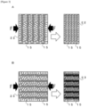
- Figure 3 illustrates schematic diagrams of respectively compressed states of a molding (A) in which the lengthwise direction of elongated pores is oriented substantially horizontally and a molding (B) in which the lengthwise direction of elongated pores is oriented substantially vertically.
- A is a porous molding 22 in which the lengthwise direction of the elongated pores 15 is oriented substantially horizontally (0° ⁇ 5°).
- B is a porous molding 23 in which the lengthwise direction of the elongated pores 15 is oriented substantially vertically (90° ⁇ 5°).
- the molding 22 When the lengthwise direction of the pores 15 and the compression direction are the same, as in the molding 22 of A, the molding 22 easily recovers to the original thickness. However, when the lengthwise direction of the pores 15 and the compression direction are substantially perpendicular, as in the molding 23 of B, the molding 23 does not recover to the original thickness as easily as the molding 22.
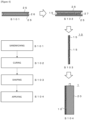
- Figure 4 illustrates a flow of steps for manufacturing a fire-spread prevention type cell unit in an embodiment of the invention and cross sections of the representative form in each step.
- the method for manufacturing a fire-spread prevention type cell unit in the embodiment is a method for manufacturing the fire-spread prevention type cell unit 1 above, and includes a sandwiching step (S101), a curing step (S102), a sheet shaping step (S103), and an applying step (S104). The following describes each step specifically.
- This step involves sandwiching a curable composition 26, which serves as the fire-spread prevention sheet after curing, between plates 25.
- the curable composition 26 is preferably capable of retaining shape, and is in a semi-cured state not fully cured, for example.
- the curable composition 26 sandwiched between the plates 25 preferably is cylindrical, prismatic, or of a similar form.
- the curable composition 26 contains an organic foaming agent for foaming during curing, for example.
- the foaming agent may be azobisisobutyronitrile (AIBN) or azodicarbonamide (ADCA), for illustrative purposes.
- AIBN azobisisobutyronitrile
- ADCA azodicarbonamide
- one example of not including an organic foaming agent is a method of using of the curable composition 26 containing thermal expandable resin beads in rubber.
- the resin beads become balloon-like during curing, and a sponge-like cured body is obtained.
- Another example of not including an organic foaming agent is a method of using of the curable composition 26 with air mixed into non-foaming liquid rubber under high pressure.
- a sponge-like cured body is obtained by curing the curable composition 26 under normal pressure.
- the foaming curable composition 26 is sandwiched by the plates 25 from both sides.
- metal plates such as aluminum plates or resin plates such as polyethylene terephthalate plates can be used.
- This step involves manufacturing a sponge-like cured body 27 by inducing foaming so that the lengthwise direction of the pores 15 points in the sandwiching direction of the plates 25 after the sandwiching step.
- the sides of the curable composition 26 do not touch the plates 25. The sides thus transfer heat more quickly than the top and bottom surfaces touching the plates 25. Accordingly, the side areas cure readily before foaming.
- the pores 15 readily elongate toward the plates 25. This completes the sponge-like cured body 27 with elongated pores 15 in the direction of the plates 25. If a curable silicone rubber composition is used as the curable composition 26, the composition is heated in this step.
- This step involves using the cured body 27 after the curing step to shape the sheet into a form with the lengthwise direction of the pores 15 pointing in the thickness direction of the fire-spread prevention sheet 10.
- One exemplary shaping method is to slice the sheet from the cured body 27.
- One example is to slice the dashed-line portion P.
- Cutting and/or polishing techniques may be used instead of slicing.
- the step for differentiating the adhesion between the application surface 11 and the outer surface 12 of the fire-spread prevention sheet 10 may be performed during or after this step.
- the outer surface 12 When processing the outer surface 12 into a rougher surface than the application surface 11, the outer surface 12 may be subjected to blast treatment.
- the application surface 11 When processing the application surface 11 into a smoother surface than the outer surface 12, the application surface 11 may be mirror polished.
- This step involves applying the fire-spread prevention sheet 10 after the sheet shaping step to the side located in the arrangement direction of the battery cells 20.
- a typical application method is to apply without any intermediary adhesive, but an adhesive or double-sided tape may also be interposed between the fire-spread prevention sheet 10 and the side of the battery cell 20.
- a foam silicone rubber molding (30 mm diameter ⁇ 10 mm thick) with vertically long pores 15 and a foam silicone rubber molding (30 mm diameter ⁇ 10 mm thick) with horizontally long pores 15 were prepared.
- a digital microscope (manufactured by KEYENCE CORPORATION) was used for cross-sectional observation.
- a spacer 9.4 mm thick was prepared from each molding, and the compression set was measured after placing the spacer in a thermostat oven at 180°C for 20 hours (JIS K 6262). Measurements were taken using a densimeter (manufactured by Alpha Mirage Co., Ltd.), and both moldings were found to have a specific gravity of 0.23 g/cm 3 . From these results, the moldings were determined to have substantially the same porosity.
- Figure 5 illustrates compression set measurement results for each molding.
- the silicone rubber molding with the lengthwise direction of the pores 15 substantially parallel to the compression direction resulted in a lower compression set than the silicone rubber molding with the lengthwise direction of the pores 15 substantially perpendicular to the compression direction ("horizontal").
- the compression set tends to be lower when the lengthwise direction of the pores 15 is closer to the compression direction, thus indicating elastic deformation.
- the specimen does not fully return to the original thickness, thus indicating a low elastic recovery ratio.
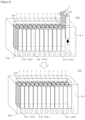
- the fire-spread prevention type cell unit 1 of the embodiment above is loaded into a battery.
- Figure 6 illustrates a perspective view of the situation when loading a fire-spread prevention type cell unit into a battery in an embodiment and the situation after loading is complete.
- the battery 30 of the embodiment is a battery for an electric vehicle, for example, and has multiple battery cells 20 arranged side-by-side.
- the number of battery cells 20 is 12 in this embodiment, but may also be 2-11, or 13 or more.
- the battery 30 is a storage battery, preferably a lithium-ion battery.
- the battery 30 includes a bottomed type enclosure 31 open on one side.
- the battery cells 20 are disposed in the interior 34 of the enclosure 31.
- the multiple battery cells 20 are tightly pressed against each other in the enclosure 31 by applying force in the direction of compressing from both sides using screws or the like (not illustrated).
- the bottom 32 of the enclosure 31 (an example of a cooling part) has one or more water-cooling pipes 33 carrying cooling water as one example of a coolant 35.
- the coolant 35 may also be referred to as a cooling medium or refrigerant.
- the battery cells 20 are disposed inside the enclosure 31 with sandwiching the fire-spread prevention sheet 10 in between adjacent battery cells 20.
- a fire-spread prevention sheet 10 sticks to a battery cell 20 to form one fire-spread prevention type cell unit 1.
- the fire-spread prevention type cell unit 1 is loaded into the interior 34 of the enclosure 31 (see the direction of arrow C).
- the fire-spread prevention sheet 10 disposed between the battery cells 20 is a porous sheet with the lengthwise direction of the pores 15 parallel in the plane of the fire-spread prevention sheet 10 and oriented in the thickness direction of the fire-spread prevention sheet 10. Therefore, even if the fire-spread prevention sheet 10 is repeatedly compressed between the battery cells 20 and then released from compression, the fire-spread prevention sheet 10 elastically deforms in the thickness direction and readily recovers to the original thickness. Thus, the fire-spread prevention sheet 10 easily maintains the form of the pores 15 for a long time, as a result, maintains thermal insulation for a long time.
- the surface roughness of the application surface 11 and outer surface 12 is compared using the arithmetic mean height (Sa) or maximum height (Sz) based on "ISO 25178: Surface texture". Instead, however, a similar comparison is possible using the arithmetic mean roughness (Ra) or maximum height (Rz) based on JIS B 0601.
- the Ra of the application surface 11 is preferably in the range of 0.02-0.4 ⁇ m, more preferably 0.02-0.2 ⁇ m.
- the Ra of the outer surface 12 is preferably in the range of 0.5-25 ⁇ m, more preferably 0.7-25 ⁇ m.
- the Rz of the application surface 11 is preferably in the range of 0.4-4 ⁇ m, more preferably 0.4-2 ⁇ m.
- the Rz of the outer surface 12 is preferably in the range of 5-300 ⁇ m, more preferably 25-300 ⁇ m.
- the length-to-width ratio (aspect ratio) of the pores 15 is not restricted insofar as the ratio exceeds 1, and is preferably 2 or greater, more preferably 3 or greater.
- the fire-spread prevention sheet 10 is repeatedly applicable to the side of the battery cell 20.
- the fire-spread prevention sheet 10 may also be fixed to the side of the battery cell 20, disallowing repeated application.
- the present invention is usable in the battery field.
Landscapes
- Chemical & Material Sciences (AREA)
- Chemical Kinetics & Catalysis (AREA)
- Electrochemistry (AREA)
- General Chemical & Material Sciences (AREA)
- Engineering & Computer Science (AREA)
- Manufacturing & Machinery (AREA)
- Battery Mounting, Suspending (AREA)
- Secondary Cells (AREA)
- Primary Cells (AREA)
Abstract
Description
- The contents of the patents, patent applications, and documents cited in this application are incorporated herein by reference.
- The present invention relates to a fire-spread prevention type cell unit having a battery cell with a fire-spread prevention sheet, a method for manufacturing the same, and a battery including the fire-spread prevention cell unit.
- Currently, there is a growing movement around the world to gradually convert conventional gasoline or diesel vehicles to electric vehicles to reduce the burden on the global environment. Particularly, electric vehicles are proliferating in European countries such as France, the Netherlands, and Germany, and also in China.
- Various batteries such as the automotive batteries above may undergo thermal runaway for some reason and catch fire or start smoking. Recently, automotive batteries with multiple battery cells juxtaposed inside an enclosure have become known. In such a battery with multiple juxtaposed battery cells, when one battery cell catches fire or starts smoking, heat is transferred to surrounding battery cells, which may lead to even greater fire, smoking, explosion, or other problems. To minimize the damage from such problems, methods for inhibiting the transfer of heat from an abnormally hot battery cell to surrounding battery cells are being considered. For example, a known method provides a fire-spread prevention sheet, such as a fireproof material or thermal insulation layer, between multiple battery cells (see Patent Literature 1).
- Patent Literature 1:
Japanese Patent Laid-Open No. 2018-206604 - A fire-spread prevention sheet desirably has low hardness and is easily deformable because of the need to reduce damage to the sheet even if the battery cells expand due to overheating. A fire-spread prevention sheet also preferably contains air to improve the thermal insulation of the sheet. To meet this demand, the inventor considered providing a porous rubber sheet on the sides of the battery cells and inserting the sheet between the battery cells. The inventor developed the porous rubber sheet to maintain the porous state of the sheet by enabling long-term elastic deformation even after repeated compression and release of the sheet. The present invention also contributes to achieving the applicant's sustainable development goal to "ensure access to affordable, reliable, sustainable and modern energy for all".
- The present invention has been made in light of the above problems, and an objective thereof is to provide a fire-spread prevention type cell unit having a battery cell with a fire-spread prevention sheet that easily deforms in response to overheating and expansion of battery cells and maintains the porosity of the sheet by enabling long-term elastic deformation, a method for manufacturing the same, and a battery.
-
- (1) To achieve the objective, a fire-spread prevention type cell unit in one embodiment includes:
- a battery cell; and
- a fire-spread prevention sheet applied to a side located in an arrangement direction of the battery cell, wherein
- the fire-spread prevention sheet is a porous sponge sheet, and
- pores inside the fire-spread prevention sheet have an elongated shape with a lengthwise direction of the pores oriented in a thickness direction of the fire-spread prevention sheet.
- (2) In a fire-spread prevention type unit in another embodiment, preferably, the adhesion of an application surface of the fire-spread prevention sheet to the battery cell may be higher than the adhesion of an outer surface located on the opposite side from the application surface in the thickness direction of the fire-spread prevention sheet.
- (3) In a fire-spread prevention type unit in another embodiment, preferably, the fire-spread prevention sheet may further include a fire retardant material.
- (4) In a fire-spread prevention type unit in another embodiment, preferably, the fire-spread prevention sheet may contain silicone rubber as a main material.
- (5) To achieve the objective, a method for manufacturing a fire-spread prevention type cell unit in one embodiment is a method for manufacturing the fire-spread prevention type cell unit of any of the above, and includes:
- a sandwiching step of sandwiching a curable composition, which serves as a fire-spread prevention sheet after curing, between plates;
- a curing step of manufacturing a sponge-like cured body by inducing foaming so that the lengthwise direction of the pores points in the sandwiching direction of the plates after the sandwiching step;
- a sheet shaping step of using the cured body to shape the sheet into a form with the lengthwise direction of the pores pointing in the thickness direction of the fire-spread prevention sheet; and
- an applying step of applying the fire-spread prevention sheet after the sheet shaping step to the side located in the arrangement direction of the battery cell.
- (6) To achieve the objective, a battery in one embodiment includes a plural arrangement of the fire-spread prevention type cell unit of any of the above.
- According to the present invention, a fire-spread prevention type cell unit having a battery cell with a fire-spread prevention sheet that easily deforms in response to overheating and expansion of battery cells and maintains the porosity of the sheet by enabling long-term elastic deformation, a method for manufacturing the same, and a battery can be provided.
-
- [
Figure 1] Figure 1 illustrates a perspective view for explaining a configuration of a fire-spread prevention type cell unit in an embodiment of the invention. - [
Figure 2] Figure 2 illustrates an A-A cross section and an enlarged view of portion B of the fire-spread prevention type cell unit inFigure 1 . - [
Figure 3] Figure 3 illustrates schematic diagrams of respectively compressed states of a molding (A) in which the lengthwise direction of elongated pores is oriented substantially horizontally and a molding (B) in which the lengthwise direction of elongated pores is oriented substantially vertically. - [
Figure 4] Figure 4 illustrates a flow of steps for manufacturing a fire-spread prevention type cell unit in an embodiment of the invention and cross sections of the representative form in each step. - [
Figure 5] Figure 5 illustrates compression set measurement results for each molding. - [
Figure 6] Figure 6 illustrates a perspective view of the situation when loading a fire-spread prevention type cell unit into a battery in an embodiment and the situation after loading is complete. - 1...fire-spread prevention type cell unit, 10...fire-spread prevention sheet, 11...application surface, 12...outer surface, 15...pore, 20...battery cell, 25...plate, 26...curable composition, 27...cured body, 30...battery.
- The following describes an embodiment of the invention with reference to the drawings. Note that the embodiment described hereinafter does not limit the invention as in the claims, and not all of the various elements and combinations thereof described in the embodiment are essential to the solution of the invention.
- First, a fire-spread prevention type cell unit of the embodiment of the invention is described with reference to the drawings.
-
Figure 1 illustrates a perspective view for explaining a configuration of a fire-spread prevention type cell unit of the embodiment of the invention.Figure 2 illustrates an A-A cross section and an enlarged view of portion B of the fire-spread prevention type cell unit inFigure 1 . - The fire-spread prevention
type cell unit 1 of the embodiment includesbattery cells 20 and fire-spread prevention sheets 10 applied to the side located in the arrangement direction of thebattery cells 20. More specifically, the fire-spread preventiontype cell unit 1 is the unification of thebattery cells 20 and the fire-spread prevention sheets 10 applied to at least one of the two sides in the direction of arranging thebattery cells 20. The fire-spread prevention sheet 10 is disposed betweenmultiple battery cells 20 inside a battery and can prevent fire-spread by inhibiting heat transfer to anotherbattery cell 20 when abattery cell 20 overheats. The fire-spread prevention sheet 10 is used by applying the broadest surface thereof to thebattery cell 20. A single configuration of the fire-spread prevention sheet 10 applied to thebattery cell 20 is referred to as the fire-spread preventiontype cell unit 1. In this embodiment, the fire-spread prevention sheet 10 adheres to thebattery cell 20 and can be applied without an intermediary layer such as a bonding agent. The thickness of the fire-spread prevention sheet 10 is not particularly restricted, but is preferably 1-20 mm, more preferably 2-8 mm. - In the fire-
spread prevention sheet 10, the adhesion of an application surface 11 to thebattery cell 20 is preferably higher than the adhesion of anouter surface 12 located on the opposite side from the application surface 11 in the thickness direction of the fire-spread prevention sheet 10. As a result, each fire-spread preventiontype cell unit 1 can be loaded into or withdrawn from the battery easily. In this application, "adhesion", unlike "bonding" or "fixing", is interpreted as a state allowing repeated application. - In the embodiment, the application surface 11 for applying the fire-
spread prevention sheet 10 to thebattery cell 20 is a highly smooth surface that can adhere with little or no air intervening state between itself and the broadest surface (side) of thebattery cell 20. The preferable surface roughness of the application surface 11, in terms of arithmetic mean height (Sa) based on "ISO 25178: Surface texture", is in the range of Sa = 0.05-0.4 µm, more preferably Sa = 0.05-0.3 µm. Meanwhile, theouter surface 12 is a less smooth surface than the application surface 11. The preferable surface roughness of theouter surface 12, in terms of arithmetic mean height (Sa) based on "ISO 25178: Surface texture", is in the range of Sa = 0.5-20 µm, more preferably Sa = 5-20 µm. - In terms of a reference other than Sa, the maximum height (Sz) based on "ISO 25178: Surface texture" is preferably greater for the
outer surface 12 than the application surface 11. The preferable surface roughness of the application surface 11, in terms of maximum height (Sz) based on "ISO 25178: Surface texture", is in the range of Sz = 0.5-5 µm, more preferably Sz = 0.5-2 µm. The preferable surface roughness of theouter surface 12, in terms of maximum height (Sz) based on "ISO 25178: Surface texture", is in the range of Sz = 5-200 µm, more preferably Sz = 20-200 µm. Note that Sa and Sz are measured avoidingopen pores 15 in the application surface 11 andouter surface 12. - When manufacturing the fire-
spread prevention sheet 10 by molding, for example, the roughness of the application surface 11 andouter surface 12 each can be obtained easily by transferring the roughness of the inner surface of the mold or a resin sheet placed inside the mold. When increasing the surface roughness of theouter surface 12 is desired, a treatment such as blasting to impinge fine particles on the surface may be performed. Increasing the surface roughness of theouter surface 12 compared to the application surface 11 in this way facilitates easy loading or withdrawal of one fire-spread preventiontype cell unit 1 at a time into or out of the battery enclosure from among multiple fire-spread preventiontype cell units 1. This is because when loading and withdrawing a fire-spread preventiontype cell unit 1, the fire-spread preventiontype cell unit 1 does not readily adhere to an adjacent fire-spread preventiontype cell unit 1. Particularly, multiple fire-spread preventiontype cell units 1 inside a battery are often compressed from the outside in the arrangement direction of the fire-spread preventiontype cell units 1 after being loaded into the battery. Even in such cases, a large surface roughness of theouter surface 12 can reduce situations where the fire-spread preventiontype cell units 1 stick to each other. A smooth application surface 11 can increase adhesive force between the fire-spread prevention sheet 10 and the side of thebattery cell 20, allowing for easy loading or withdrawal of one fire-spread preventiontype cell unit 1 at a time into or out of the battery. - Note that the means of making the
outer surface 12 less adhesive than the application surface 11 is not limited to differentiating the surface roughness described above, and may be other means. The other means may be, for example, forming the fire-spread prevention sheet 10 with two layers of sheets, with the sheet on theouter surface 12 side having greater hardness than the sheet on the application surface 11 side. - In this embodiment, the fire-
spread prevention sheet 10 is substantially the same size as the broadest surface (side) of thebattery cell 20, but may also be larger or smaller than the side. However, to enhance fire-spread prevention, the fire-spread prevention sheet 10 is preferably the same size or larger than the side of thebattery cell 20. - In this embodiment, the fire-
spread prevention sheet 10 is a porous sponge sheet. The sponge sheet haspores 15 that are preferably 40-95% by volume, more preferably 60-90% by volume, of the total volume of the sheet. Air inside thepores 15 of the sponge sheet provides excellent thermal insulation to the fire-spread prevention sheet 10. The fire-spread prevention sheet 10 thus contributes to low thermal conductivity between neighboringbattery cells 20. Thepores 15 have an elongated, that is, anisotropic shape, and the lengthwise direction of thepores 15 is oriented in the thickness direction of the fire-spread prevention sheet 10. The lengthwise direction of thepores 15 is substantially parallel (0°±5°) to the thickness direction of the fire-spread prevention sheet 10. However, some of themultiple pores 15 may have a shape other than elongated, or pores 15 may exist which have an elongated shape but for which the lengthwise direction is not parallel to the thickness direction. At least 50%, preferably at least 70%, more preferably at least 90% of the total number ofpores 15 may have an elongated shape and may be oriented with the lengthwise direction substantially parallel to the thickness direction of the fire-spread prevention sheet 10. - As illustrated in
Figure 2 , in the fire-spread prevention sheet 10, theelongated pores 15 are oriented with the lengthwise direction of thepores 15 pointing in the thickness direction of the sheet. In this case, when the fire-spread prevention sheet 10 is compressed in the thickness direction thereof (that is, inFigure 2 , when the fire-spread prevention sheet 10 is subjected to force in direction of arrows F from both sides in the thickness direction), the fire-spread prevention sheet 10 elastically deforms and reduces in thickness, and elastically deforms to the original thickness when the force from arrows F is released. Therefore, thepores 15 can maintain the original shape or a shape close thereto. In this way, the fire-spread prevention sheet 10 can maintain porosity even after repeated compression and release of the fire-spread prevention sheet 10. Accordingly, high thermal insulation of the fire-spread prevention sheet 10 can also be maintained. - The fire-
spread prevention sheet 10 is formed mainly from resin or rubber, preferably rubber. The rubber includes, for example, a thermosetting elastomer such as silicone rubber, urethane rubber, isoprene rubber, ethylene propylene rubber, natural rubber, ethylene propylene diene rubber, nitrile rubber (NBR), or styrene butadiene rubber (SBR); a thermoplastic elastomer such as urethane, ester, styrene, olefin, butadiene, or fluorine, or a composite thereof. Among rubbers, silicone rubber with relatively high heat resistance is more suitable. The fire-spread prevention sheet 10 preferably contains silicone rubber as a main material. The fire-spread prevention sheet 10 more preferably is a porous silicone rubber sponge sheet. Note that in this application, "mainly" or "main material" is interpreted to exceed 50% by mass of the total materials. - The fire-
spread prevention sheet 10 preferably contains a fire retardant material to further enhance fire-spread prevention ability. The fire retardant material is preferably one or more inorganic compounds such as carbon (including amorphous carbon and graphite), halide, phosphorus compound, platinum, platinum complex, magnesium hydroxide, or aluminum hydroxide. The fire retardant material is preferably 0.5-20% by mass, more preferably 1-20% by mass, of the total mass of the fire-spread prevention sheet 10. -
Figure 3 illustrates schematic diagrams of respectively compressed states of a molding (A) in which the lengthwise direction of elongated pores is oriented substantially horizontally and a molding (B) in which the lengthwise direction of elongated pores is oriented substantially vertically. - A is a
porous molding 22 in which the lengthwise direction of the elongated pores 15 is oriented substantially horizontally (0°±5°). B is aporous molding 23 in which the lengthwise direction of the elongated pores 15 is oriented substantially vertically (90°±5°). When themoldings moldings moldings molding 23 of B does not return to the original thickness as easily as themolding 22 of A. The degree of recovery from such elastic deformation depends on the relationship between the lengthwise direction of thepores 15 and the compression direction. When the lengthwise direction of thepores 15 and the compression direction are the same, as in themolding 22 of A, themolding 22 easily recovers to the original thickness. However, when the lengthwise direction of thepores 15 and the compression direction are substantially perpendicular, as in themolding 23 of B, themolding 23 does not recover to the original thickness as easily as themolding 22. - Next, a method for manufacturing a fire-spread prevention type cell unit of the embodiment of the invention is described with reference to the drawings.
-
Figure 4 illustrates a flow of steps for manufacturing a fire-spread prevention type cell unit in an embodiment of the invention and cross sections of the representative form in each step. - The method for manufacturing a fire-spread prevention type cell unit in the embodiment is a method for manufacturing the fire-spread prevention
type cell unit 1 above, and includes a sandwiching step (S101), a curing step (S102), a sheet shaping step (S103), and an applying step (S104). The following describes each step specifically. - This step involves sandwiching a
curable composition 26, which serves as the fire-spread prevention sheet after curing, betweenplates 25. Thecurable composition 26 is preferably capable of retaining shape, and is in a semi-cured state not fully cured, for example. Thecurable composition 26 sandwiched between theplates 25 preferably is cylindrical, prismatic, or of a similar form. Thecurable composition 26 contains an organic foaming agent for foaming during curing, for example. The foaming agent may be azobisisobutyronitrile (AIBN) or azodicarbonamide (ADCA), for illustrative purposes. Note that one example of not including an organic foaming agent is a method of using of thecurable composition 26 containing thermal expandable resin beads in rubber. In this case, the resin beads become balloon-like during curing, and a sponge-like cured body is obtained. Another example of not including an organic foaming agent is a method of using of thecurable composition 26 with air mixed into non-foaming liquid rubber under high pressure. In this case, a sponge-like cured body is obtained by curing thecurable composition 26 under normal pressure. Irrespective of the foaming method, in the sandwiching step, the foamingcurable composition 26 is sandwiched by theplates 25 from both sides. There are no restrictions on the component material of theplates 25 insofar as the shape can be maintained when curing thecurable composition 26, and for example, metal plates such as aluminum plates or resin plates such as polyethylene terephthalate plates can be used. - This step involves manufacturing a sponge-like cured
body 27 by inducing foaming so that the lengthwise direction of thepores 15 points in the sandwiching direction of theplates 25 after the sandwiching step. The sides of thecurable composition 26 do not touch theplates 25. The sides thus transfer heat more quickly than the top and bottom surfaces touching theplates 25. Accordingly, the side areas cure readily before foaming. As a result, inside thecurable composition 26, thepores 15 readily elongate toward theplates 25. This completes the sponge-like curedbody 27 withelongated pores 15 in the direction of theplates 25. If a curable silicone rubber composition is used as thecurable composition 26, the composition is heated in this step. - This step involves using the cured
body 27 after the curing step to shape the sheet into a form with the lengthwise direction of thepores 15 pointing in the thickness direction of the fire-spread prevention sheet 10. One exemplary shaping method is to slice the sheet from the curedbody 27. One example is to slice the dashed-line portion P. Cutting and/or polishing techniques may be used instead of slicing. The step for differentiating the adhesion between the application surface 11 and theouter surface 12 of the fire-spread prevention sheet 10 may be performed during or after this step. When processing theouter surface 12 into a rougher surface than the application surface 11, theouter surface 12 may be subjected to blast treatment. When processing the application surface 11 into a smoother surface than theouter surface 12, the application surface 11 may be mirror polished. - This step involves applying the fire-
spread prevention sheet 10 after the sheet shaping step to the side located in the arrangement direction of thebattery cells 20. A typical application method is to apply without any intermediary adhesive, but an adhesive or double-sided tape may also be interposed between the fire-spread prevention sheet 10 and the side of thebattery cell 20. - The following describes the method and results of compression set testing of different compression directions relative to the pore direction.
- First, a foam silicone rubber molding (30 mm diameter × 10 mm thick) with vertically
long pores 15 and a foam silicone rubber molding (30 mm diameter × 10 mm thick) with horizontally long pores 15 were prepared. A digital microscope (manufactured by KEYENCE CORPORATION) was used for cross-sectional observation. A spacer 9.4 mm thick was prepared from each molding, and the compression set was measured after placing the spacer in a thermostat oven at 180°C for 20 hours (JIS K 6262). Measurements were taken using a densimeter (manufactured by Alpha Mirage Co., Ltd.), and both moldings were found to have a specific gravity of 0.23 g/cm3. From these results, the moldings were determined to have substantially the same porosity. -
Figure 5 illustrates compression set measurement results for each molding. - As the table in
Figure 5 indicates, the silicone rubber molding with the lengthwise direction of thepores 15 substantially parallel to the compression direction ("vertical") resulted in a lower compression set than the silicone rubber molding with the lengthwise direction of thepores 15 substantially perpendicular to the compression direction ("horizontal"). The compression set tends to be lower when the lengthwise direction of thepores 15 is closer to the compression direction, thus indicating elastic deformation. Meanwhile, when the lengthwise direction of thepores 15 is substantially perpendicular to the compression direction, the specimen does not fully return to the original thickness, thus indicating a low elastic recovery ratio. - Next, a battery in an embodiment of the invention is described with reference to the drawings. The fire-spread prevention
type cell unit 1 of the embodiment above is loaded into a battery. -
Figure 6 illustrates a perspective view of the situation when loading a fire-spread prevention type cell unit into a battery in an embodiment and the situation after loading is complete. - The
battery 30 of the embodiment is a battery for an electric vehicle, for example, and hasmultiple battery cells 20 arranged side-by-side. The number ofbattery cells 20 is 12 in this embodiment, but may also be 2-11, or 13 or more. Thebattery 30 is a storage battery, preferably a lithium-ion battery. Thebattery 30 includes a bottomedtype enclosure 31 open on one side. Thebattery cells 20 are disposed in theinterior 34 of theenclosure 31. Preferably, themultiple battery cells 20 are tightly pressed against each other in theenclosure 31 by applying force in the direction of compressing from both sides using screws or the like (not illustrated). The bottom 32 of the enclosure 31 (an example of a cooling part) has one or more water-cooling pipes 33 carrying cooling water as one example of acoolant 35. Thecoolant 35 may also be referred to as a cooling medium or refrigerant. Thebattery cells 20 are disposed inside theenclosure 31 with sandwiching the fire-spread prevention sheet 10 in betweenadjacent battery cells 20. A fire-spread prevention sheet 10 sticks to abattery cell 20 to form one fire-spread preventiontype cell unit 1. The fire-spread preventiontype cell unit 1 is loaded into the interior 34 of the enclosure 31 (see the direction of arrow C). - The fire-
spread prevention sheet 10 disposed between thebattery cells 20 is a porous sheet with the lengthwise direction of thepores 15 parallel in the plane of the fire-spread prevention sheet 10 and oriented in the thickness direction of the fire-spread prevention sheet 10. Therefore, even if the fire-spread prevention sheet 10 is repeatedly compressed between thebattery cells 20 and then released from compression, the fire-spread prevention sheet 10 elastically deforms in the thickness direction and readily recovers to the original thickness. Thus, the fire-spread prevention sheet 10 easily maintains the form of thepores 15 for a long time, as a result, maintains thermal insulation for a long time. - The above describes an embodiment of the invention, but the present invention is not limited thereto and may be modified in various ways.
- In the embodiment above, the surface roughness of the application surface 11 and
outer surface 12 is compared using the arithmetic mean height (Sa) or maximum height (Sz) based on "ISO 25178: Surface texture". Instead, however, a similar comparison is possible using the arithmetic mean roughness (Ra) or maximum height (Rz) based on JIS B 0601. In this case, the Ra of the application surface 11 is preferably in the range of 0.02-0.4 µm, more preferably 0.02-0.2 µm. The Ra of theouter surface 12 is preferably in the range of 0.5-25 µm, more preferably 0.7-25 µm. The Rz of the application surface 11 is preferably in the range of 0.4-4 µm, more preferably 0.4-2 µm. The Rz of theouter surface 12 is preferably in the range of 5-300 µm, more preferably 25-300 µm. - The length-to-width ratio (aspect ratio) of the
pores 15 is not restricted insofar as the ratio exceeds 1, and is preferably 2 or greater, more preferably 3 or greater. - Preferably, the fire-
spread prevention sheet 10 is repeatedly applicable to the side of thebattery cell 20. However, the fire-spread prevention sheet 10 may also be fixed to the side of thebattery cell 20, disallowing repeated application. - The multiple components of the embodiments above may be combined with each other freely except when combination is unfeasible.
- The present invention is usable in the battery field.
Claims (6)
- A fire-spread prevention type cell unit, comprising:a battery cell; anda fire-spread prevention sheet applied to a side located in an arrangement direction of the battery cell, whereinthe fire-spread prevention sheet is a porous sponge sheet, andpores inside the fire-spread prevention sheet have an elongated shape with a lengthwise direction of the pores oriented in a thickness direction of the fire-spread prevention sheet.
- The fire-spread prevention type cell unit of claim 1, wherein, in the fire-spread prevention sheet, the adhesion of an application surface to the battery cell is higher than the adhesion of an outer surface located on the opposite side from the application surface in the thickness direction of the fire-spread prevention sheet.
- The fire-spread prevention type cell unit of claim 1 or 2, wherein the fire-spread prevention sheet further includes a fire retardant material.
- The fire-spread prevention type cell unit of any one of claims 1 to 3, wherein the fire-spread prevention sheet contains silicone rubber as a main material.
- A method for manufacturing the fire-spread prevention type cell unit of any one of claims 1 to 4, the method comprising:a sandwiching step of sandwiching a curable composition, which serves as a fire-spread prevention sheet after curing, between plates;a curing step of manufacturing a sponge-like cured body by inducing foaming so that the lengthwise direction of the pores points in the sandwiching direction of the plates after the sandwiching step;a sheet shaping step of using the cured body to shape the sheet into a form with the lengthwise direction of the pores pointing in the thickness direction of the fire-spread prevention sheet; andan applying step of applying the fire-spread prevention sheet after the sheet shaping step to the side located in the arrangement direction of the battery cell.
- A battery comprising a plural arrangement of the fire-spread prevention type cell unit of any one of claims 1 to 4.
Applications Claiming Priority (1)
| Application Number | Priority Date | Filing Date | Title |
|---|---|---|---|
| PCT/JP2021/032249 WO2023032114A1 (en) | 2021-09-02 | 2021-09-02 | Fire-spread prevention type cell unit, method for manufacturing same, and battery |
Publications (2)
| Publication Number | Publication Date |
|---|---|
| EP4343929A1 true EP4343929A1 (en) | 2024-03-27 |
| EP4343929A4 EP4343929A4 (en) | 2025-03-05 |
Family
ID=85410995
Family Applications (1)
| Application Number | Title | Priority Date | Filing Date |
|---|---|---|---|
| EP21956003.4A Pending EP4343929A4 (en) | 2021-09-02 | 2021-09-02 | FIRE SPREAD PREVENTION TYPE CELL UNIT, MANUFACTURING METHOD THEREFOR, AND BATTERY |
Country Status (6)
| Country | Link |
|---|---|
| US (1) | US20240322359A1 (en) |
| EP (1) | EP4343929A4 (en) |
| JP (1) | JP7395074B2 (en) |
| KR (1) | KR20240006687A (en) |
| CN (1) | CN117461194A (en) |
| WO (1) | WO2023032114A1 (en) |
Families Citing this family (2)
| Publication number | Priority date | Publication date | Assignee | Title |
|---|---|---|---|---|
| JP2025034691A (en) * | 2023-08-31 | 2025-03-13 | イビデン株式会社 | Flame retardant sheet, its manufacturing method, and battery pack |
| JPWO2025115971A1 (en) * | 2023-11-29 | 2025-06-05 |
Family Cites Families (7)
| Publication number | Priority date | Publication date | Assignee | Title |
|---|---|---|---|---|
| EP2555276A1 (en) * | 2010-03-30 | 2013-02-06 | Panasonic Corporation | Battery pack |
| JP2013004294A (en) * | 2011-06-16 | 2013-01-07 | Nissan Motor Co Ltd | Battery pack |
| JP2013187079A (en) * | 2012-03-08 | 2013-09-19 | Hitachi Maxell Ltd | Heat exchanger plate for battery pack and method of manufacturing the same |
| JP2018206604A (en) | 2017-06-05 | 2018-12-27 | 積水化学工業株式会社 | Cell, battery module, battery pack, and battery |
| TW201945200A (en) * | 2018-02-20 | 2019-12-01 | 日商積水化學工業股份有限公司 | Fireproof laminate and battery |
| EP3942215B1 (en) * | 2019-03-21 | 2025-12-31 | Hefei Gotion High-Tech Power Energy Co., Ltd. | THERMAL INSULATION COMPOSITE MATERIALS |
| JP7422739B2 (en) * | 2019-03-27 | 2024-01-26 | 三洋電機株式会社 | Power supplies and electric vehicles |
-
2021
- 2021-09-02 EP EP21956003.4A patent/EP4343929A4/en active Pending
- 2021-09-02 WO PCT/JP2021/032249 patent/WO2023032114A1/en not_active Ceased
- 2021-09-02 JP JP2023544903A patent/JP7395074B2/en active Active
- 2021-09-02 US US18/577,694 patent/US20240322359A1/en active Pending
- 2021-09-02 CN CN202180099359.7A patent/CN117461194A/en active Pending
- 2021-09-02 KR KR1020237043021A patent/KR20240006687A/en active Pending
Also Published As
| Publication number | Publication date |
|---|---|
| US20240322359A1 (en) | 2024-09-26 |
| EP4343929A4 (en) | 2025-03-05 |
| JP7395074B2 (en) | 2023-12-08 |
| WO2023032114A1 (en) | 2023-03-09 |
| JPWO2023032114A1 (en) | 2023-03-09 |
| KR20240006687A (en) | 2024-01-15 |
| CN117461194A (en) | 2024-01-26 |
Similar Documents
| Publication | Publication Date | Title |
|---|---|---|
| EP4343929A1 (en) | Fire-spread prevention type cell unit, method for manufacturing same, and battery | |
| JP7628067B2 (en) | Fire-prevention cell unit, its manufacturing method, and battery | |
| US11398653B2 (en) | Cure-in-place lightweight thermally-conductive interface | |
| JP6885791B2 (en) | Thermal runaway prevention sheet | |
| JP7472301B2 (en) | Heat insulating pad and its manufacturing method, battery pack and device | |
| EP2442380A1 (en) | Battery pack | |
| EP2555276A1 (en) | Battery pack | |
| JP2017022081A (en) | Containment system and method for high energy density devices | |
| CN216161818U (en) | Heat insulation sheet, battery module and battery pack | |
| WO2022023903A1 (en) | Article with thermal insulation properties | |
| CN108305967B (en) | Manufacturing method of soft pack battery module, soft pack battery module and power battery system | |
| TW202344537A (en) | Battery module with polyorganosiloxane foam barrier | |
| US20240356139A1 (en) | Elastic member for battery pack and manufacturing method thereof | |
| EP4645530A1 (en) | Heat transfer suppression sheet and battery pack | |
| US20250174767A1 (en) | Thermal management assembly comprising expandable material | |
| EP4536756A1 (en) | Intumescent sheet used in an electric vehicle battery for thermal runaway management | |
| JP2025123899A (en) | Fire prevention sheet, multi-layer fire prevention sheet, manufacturing method thereof, and battery | |
| EP4685963A1 (en) | Heat transfer suppression sheet, method for producing same, and battery pack | |
| WO2025197214A1 (en) | Cushion member, method for manufacturing same, and battery | |
| JP7679332B2 (en) | Fire prevention sheet, method for producing fire prevention sheet, and battery | |
| WO2021059929A1 (en) | Method for manufacturing heat-insulating member | |
| WO2024000118A1 (en) | Battery module with polyorganosiloxane foam barrier | |
| JP2024044252A (en) | Heat insulating silicone sponge, its manufacturing method, and unit including heat insulating silicone sponge | |
| JP2025137393A (en) | Foam, components, and heat dissipation structures | |
| WO2025187700A1 (en) | Foam, member, and heat dissipation structure |
Legal Events
| Date | Code | Title | Description |
|---|---|---|---|
| STAA | Information on the status of an ep patent application or granted ep patent |
Free format text: STATUS: THE INTERNATIONAL PUBLICATION HAS BEEN MADE |
|
| PUAI | Public reference made under article 153(3) epc to a published international application that has entered the european phase |
Free format text: ORIGINAL CODE: 0009012 |
|
| STAA | Information on the status of an ep patent application or granted ep patent |
Free format text: STATUS: REQUEST FOR EXAMINATION WAS MADE |
|
| 17P | Request for examination filed |
Effective date: 20231220 |
|
| AK | Designated contracting states |
Kind code of ref document: A1 Designated state(s): AL AT BE BG CH CY CZ DE DK EE ES FI FR GB GR HR HU IE IS IT LI LT LU LV MC MK MT NL NO PL PT RO RS SE SI SK SM TR |
|
| DAV | Request for validation of the european patent (deleted) | ||
| DAX | Request for extension of the european patent (deleted) | ||
| A4 | Supplementary search report drawn up and despatched |
Effective date: 20250204 |
|
| RIC1 | Information provided on ipc code assigned before grant |
Ipc: H01M 50/383 20210101ALI20250130BHEP Ipc: H01M 50/293 20210101ALI20250130BHEP Ipc: H01M 50/24 20210101ALI20250130BHEP Ipc: H01M 50/209 20210101ALI20250130BHEP Ipc: H01M 50/291 20210101ALI20250130BHEP Ipc: H01M 50/204 20210101ALI20250130BHEP Ipc: H01M 10/658 20140101AFI20250130BHEP |