EP4343923A1 - Case for battery module and battery pack - Google Patents
Case for battery module and battery pack Download PDFInfo
- Publication number
- EP4343923A1 EP4343923A1 EP23197274.6A EP23197274A EP4343923A1 EP 4343923 A1 EP4343923 A1 EP 4343923A1 EP 23197274 A EP23197274 A EP 23197274A EP 4343923 A1 EP4343923 A1 EP 4343923A1
- Authority
- EP
- European Patent Office
- Prior art keywords
- coolant flow
- case
- plate
- battery
- coolant
- Prior art date
- Legal status (The legal status is an assumption and is not a legal conclusion. Google has not performed a legal analysis and makes no representation as to the accuracy of the status listed.)
- Granted
Links
Images



Classifications
-
- H—ELECTRICITY
- H01—ELECTRIC ELEMENTS
- H01M—PROCESSES OR MEANS, e.g. BATTERIES, FOR THE DIRECT CONVERSION OF CHEMICAL ENERGY INTO ELECTRICAL ENERGY
- H01M10/00—Secondary cells; Manufacture thereof
- H01M10/60—Heating or cooling; Temperature control
- H01M10/65—Means for temperature control structurally associated with the cells
- H01M10/655—Solid structures for heat exchange or heat conduction
- H01M10/6556—Solid parts with flow channel passages or pipes for heat exchange
-
- H—ELECTRICITY
- H01—ELECTRIC ELEMENTS
- H01M—PROCESSES OR MEANS, e.g. BATTERIES, FOR THE DIRECT CONVERSION OF CHEMICAL ENERGY INTO ELECTRICAL ENERGY
- H01M10/00—Secondary cells; Manufacture thereof
- H01M10/60—Heating or cooling; Temperature control
- H01M10/61—Types of temperature control
- H01M10/613—Cooling or keeping cold
-
- H—ELECTRICITY
- H01—ELECTRIC ELEMENTS
- H01M—PROCESSES OR MEANS, e.g. BATTERIES, FOR THE DIRECT CONVERSION OF CHEMICAL ENERGY INTO ELECTRICAL ENERGY
- H01M10/00—Secondary cells; Manufacture thereof
- H01M10/60—Heating or cooling; Temperature control
- H01M10/64—Heating or cooling; Temperature control characterised by the shape of the cells
- H01M10/647—Prismatic or flat cells, e.g. pouch cells
-
- H—ELECTRICITY
- H01—ELECTRIC ELEMENTS
- H01M—PROCESSES OR MEANS, e.g. BATTERIES, FOR THE DIRECT CONVERSION OF CHEMICAL ENERGY INTO ELECTRICAL ENERGY
- H01M10/00—Secondary cells; Manufacture thereof
- H01M10/60—Heating or cooling; Temperature control
- H01M10/65—Means for temperature control structurally associated with the cells
- H01M10/656—Means for temperature control structurally associated with the cells characterised by the type of heat-exchange fluid
-
- H—ELECTRICITY
- H01—ELECTRIC ELEMENTS
- H01M—PROCESSES OR MEANS, e.g. BATTERIES, FOR THE DIRECT CONVERSION OF CHEMICAL ENERGY INTO ELECTRICAL ENERGY
- H01M10/00—Secondary cells; Manufacture thereof
- H01M10/60—Heating or cooling; Temperature control
- H01M10/65—Means for temperature control structurally associated with the cells
- H01M10/656—Means for temperature control structurally associated with the cells characterised by the type of heat-exchange fluid
- H01M10/6567—Liquids
- H01M10/6568—Liquids characterised by flow circuits, e.g. loops, located externally to the cells or cell casings
-
- H—ELECTRICITY
- H01—ELECTRIC ELEMENTS
- H01M—PROCESSES OR MEANS, e.g. BATTERIES, FOR THE DIRECT CONVERSION OF CHEMICAL ENERGY INTO ELECTRICAL ENERGY
- H01M10/00—Secondary cells; Manufacture thereof
- H01M10/04—Construction or manufacture in general
-
- H—ELECTRICITY
- H01—ELECTRIC ELEMENTS
- H01M—PROCESSES OR MEANS, e.g. BATTERIES, FOR THE DIRECT CONVERSION OF CHEMICAL ENERGY INTO ELECTRICAL ENERGY
- H01M50/00—Constructional details or processes of manufacture of the non-active parts of electrochemical cells other than fuel cells, e.g. hybrid cells
- H01M50/20—Mountings; Secondary casings or frames; Racks, modules or packs; Suspension devices; Shock absorbers; Transport or carrying devices; Holders
- H01M50/204—Racks, modules or packs for multiple batteries or multiple cells
- H01M50/207—Racks, modules or packs for multiple batteries or multiple cells characterised by their shape
- H01M50/209—Racks, modules or packs for multiple batteries or multiple cells characterised by their shape adapted for prismatic or rectangular cells
-
- H—ELECTRICITY
- H01—ELECTRIC ELEMENTS
- H01M—PROCESSES OR MEANS, e.g. BATTERIES, FOR THE DIRECT CONVERSION OF CHEMICAL ENERGY INTO ELECTRICAL ENERGY
- H01M50/00—Constructional details or processes of manufacture of the non-active parts of electrochemical cells other than fuel cells, e.g. hybrid cells
- H01M50/20—Mountings; Secondary casings or frames; Racks, modules or packs; Suspension devices; Shock absorbers; Transport or carrying devices; Holders
- H01M50/204—Racks, modules or packs for multiple batteries or multiple cells
- H01M50/207—Racks, modules or packs for multiple batteries or multiple cells characterised by their shape
- H01M50/211—Racks, modules or packs for multiple batteries or multiple cells characterised by their shape adapted for pouch cells
-
- Y—GENERAL TAGGING OF NEW TECHNOLOGICAL DEVELOPMENTS; GENERAL TAGGING OF CROSS-SECTIONAL TECHNOLOGIES SPANNING OVER SEVERAL SECTIONS OF THE IPC; TECHNICAL SUBJECTS COVERED BY FORMER USPC CROSS-REFERENCE ART COLLECTIONS [XRACs] AND DIGESTS
- Y02—TECHNOLOGIES OR APPLICATIONS FOR MITIGATION OR ADAPTATION AGAINST CLIMATE CHANGE
- Y02E—REDUCTION OF GREENHOUSE GAS [GHG] EMISSIONS, RELATED TO ENERGY GENERATION, TRANSMISSION OR DISTRIBUTION
- Y02E60/00—Enabling technologies; Technologies with a potential or indirect contribution to GHG emissions mitigation
- Y02E60/10—Energy storage using batteries
Definitions
- the present disclosure relates to a case for a battery module and a battery pack.
- a battery module is formed to have a structure in which a plurality of cells are aggregated through a series connection and/or parallel connections.
- a battery module typically includes a cell assembly in which a plurality of cells are arranged and stacked in one direction, and a frame having plates configured to accommodate the cell assembly.
- the battery module is designed to have a cooling channel through which a coolant for cooling battery cells flows.
- process costs are increased by adding separate components to install such a cooling channel.
- One aspect of the present disclosures provides a case for a battery module that can reduce assembly processes during assembly.
- a case for a battery module may include: a body having an internal space; and an end plate disposed on an end of the body, wherein the body may include a bottom plate having at least one coolant flow path through which a coolant flows, and the end plate may include a coolant flow tube through which the coolant flows and at least one connection portion extending from the coolant flow tube and coupled to the at least one coolant flow path of the bottom plate.
- the end plate may include a plate portion having a lattice shape on one surface thereof and an extension portion extending from the plate portion, and the coolant flow tube may be connected to an end of the extension portion.
- the coolant flow tube may be formed integrally with the plate portion of the end plate.
- the at least one connection portion may comprise plural connection portions and the plural connection portions extend toward the bottom plate, and the coolant flow paths are coupled to the plural connection portions.
- the coolant flow tube may be formed along a bottom end of one surface of the end plate.
- the coolant flow tube may be formed along a top end and a bottom end of one surface of the end plate.
- connection portion When the end plate is coupled to the body, the connection portion may be coupled to the coolant flow path of the bottom plate.
- One surface of the plate portion may be lattice-shaped.
- the coolant flow tube, the plate portion, the extension portion, and the connection portion may be integrally molded.
- a battery pack may include: a plurality of battery modules, each including a case for a battery module, wherein the case for the battery module includes a body having an internal space, and an end plate disposed on an end of the body, wherein the body includes a bottom plate having at least one coolant flow path through which a coolant flows, and wherein the end plate includes a coolant flow tube through which the coolant flows and at least one connection portion extending from the coolant flow tube and coupled to the at least one coolant flow path of the bottom plate; and a frame arranged to surround the plurality of battery modules.
- the frame may have a band shape in which a top portion and a bottom portion thereof is open.
- the plurality of battery modules may be disposed in adjacent battery cases, and the coolant flow tube in a first battery case may be connected to an adjacent coolant flow tube in a second battery case through a connection hose.
- the frame may include a coolant inlet and a coolant outlet, and the coolant flow tube may be connected to the coolant inlet or the coolant outlet.
- assembly processes can be reduced during assembly.
- FIG. 1 is a perspective view illustrating a case for a battery module according to one embodiment of the present disclosure
- FIG. 2 is a perspective view illustrating an end plate of a case for a battery module according to another embodiment of the present disclosure
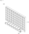
- FIG. 3 is a perspective view illustrating an end plate at an angle different from that of FIG. 2
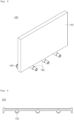
- FIG. 4 is a descriptive view illustrating a coolant flow path provided on a bottom plate of a case for a battery module according to yet another embodiment of the present disclosure.
- a case 100 for a battery module includes a body 120 and an end plate 160.
- the body 120 has an internal space.
- the body 120 may include a bottom plate 130, a side plate 140, and a top plate 150.
- the bottom plate 130, the side plate 140, and the top plate 150 may be coupled to have a rectangular cuboid shape in which both ends are open.
- the bottom plate 130 and the side plate 140 may be integrally formed and may have a shape in which the top plate 150 is coupled thereto.
- the bottom plate 130, the side plate 140, and the top plate 150 may be, for example, metal plates such as relatively thin aluminum plates.
- the bottom plate 130 includes a coolant flow path 132 through which a coolant flows, and the coolant flow path 132 may be provided in plural on the bottom plate 130. Furthermore, the coolant flow path 132 may have a circular tubular shape, as shown in FIG. 4 , providing a passage for coolant flow. However, the disclosed technology is not limited thereto, and the shape of the coolant flow path 132 may have other shapes Slits may be provided on a top surface of the bottom plate 130 to form a plurality of rows in which battery cells are inserted according to respective shapes thereof (e.g., a prismatic shape, a cylindrical shape, a pouch type, and the like). For example, a plurality of slits may be spaced apart from each other in an X-axis direction of FIG. 1 .
- the side plate 140 may be coupled to both sides of the bottom plate 130 and may have a shape having a narrow width and a long length. That is, the side plate 140 may have a plate shape having a long length in the X-axis direction of FIG. 1 and a relatively shorter length in a Z-axis direction of FIG. 1 .
- the top plate 150 is disposed to face the bottom plate 130.
- the top plate 150 may be coupled to a top surface of the side plate 140 and may have a rectangular plate shape. Additionally, the top plate 150 may be provided with slits disposed to form a plurality of rows in which battery cells are inserted.
- the side plate 140 and the top plate 150 may be formed integrally with each other.
- the side plate 140 and the top plate 150 formed integrally with each other are coupled to the bottom plate 130.
- pouch cells are disposed in an internal space of the case 100 for a battery module, with each of the pouch cells having a thin plate-shaped body, and having a structure in which an anode, a separator, and a cathode are alternately stacked and an electrode tab is drawn out to at least one side thereof.
- the anode and the cathode can be manufactured by coating a slurry such as an electrode active material, a binder resin, a conductive agent, and other additives, on at least one surface of a current collector.
- positive electrode active materials such as a lithium-containing transition metal oxide may be used for the anode
- cathode active materials such as lithium metal, a carbon material, and a metal compound, and/or mixtures thereof, in which lithium ions may be absorbed and discharged, may be used for the cathode.
- a porous polymer film used in a lithium secondary battery may be adopted as the separator.
- the pouch case is formed of a sheet material and includes an accommodation portion for accommodating an electrode assembly.
- the pouch case is formed by combining a first case and a second case formed by processing a sheet material to have a predetermined shape.
- the sheet material forming the pouch case may be comprised of a multilayer structure comprising a stack of an outermost external resin layer formed of an insulating material such as polyethylene terephthalate (PET) or nylon, an aluminum metal layer for maintaining mechanical strength and preventing penetration of moisture and oxygen, and an internal resin layer formed of a polyolefin-based material having thermal adhesiveness and serving as a sealing material.
- an adhesive resin layer may be interposed between the internal resin layer and the metal layer and between the external resin layer and the metal layer.
- the adhesive resin layer may be formed in a single layer or multiple layers for smooth adhesion between heterogeneous materials, and a material thereof may generally be a polyolefin-based resin or a polyurethane resin for smooth processing, or a mixture thereof may be adopted as the material.
- a plurality of pouch cells may be arranged in one direction.
- the plurality of pouch cells may be spaced apart from each other in the X-axis direction of FIG. 1 .
- the battery cell is not limited thereto a pouch cell, and the battery cell may be a prismatic battery cell in which an electrode assembly is accommodated in a rectangular cuboid shape housing.
- an anode tab and a cathode tab may be configured to be drawn out to a top portion (in the Z-axis direction of FIG. 1 ) and the prismatic battery cells may be stacked in the X-axis direction of FIG. 1 and may be seated in the battery module case. Furthermore, the anode tab and the cathode tab may be configured to be drawn out on both sides or one side in the Y-axis direction of FIG. 1 , respectively.
- the end plate 160 is coupled to both ends of the body 120.
- the end plate 160 may include a plate portion 162 having a lattice shape on one side thereof, an extension portion 164 extending from the plate portion 162, a coolant flow tube 166 connected to an end of the extension portion 164, and a connection portion 168 (as illustrated in FIG. 3 ) extending from the coolant flow tube 166 to the bottom plate 130 of the body 120.
- One surface of the plate portion 162 may have a lattice shape. Accordingly, the plate portion 162 may better withstand pressing force due to swelling generated by a plurality of battery cells. Accordingly, the battery cells may be more firmly connected to each other in the X-axis direction of FIG. 1 while limiting the swelling of the battery cells.
- the extension portion 164 may extend from one surface of the plate portion 162 and may be disposed in a bottom end portion of the plate portion 162.
- the extension portion 164 serves to connect the plate portion 162 and the coolant flow tube 166.
- the shape of the extension portion 164 is not limited to the shape illustrated in FIG. 2 , and may also be a bar shape connecting the plate portion 162 and the coolant flow tube 166.
- the coolant flow tube 166 has a circular tube shape and provides a flow path through which the coolant flows.
- the coolant flow tube 166 may be disposed in parallel with the plate portion 162.
- connection portion 168 may extend from the coolant flow tube 166 to the bottom plate 130, and may have a circular tube shape to be coupled to the coolant flow path 132 of the bottom plate 130. In this manner, the connection portion 168 may be connected to the coolant flow path 132 of the bottom plate 130, as illustrated in FIG. 4 , thus providing a coolant supplied to the coolant flow tube 166 to the coolant flow path 132 of the bottom plate 130. Furthermore, a plurality of connection portions 168 may be spaced apart from each other.
- the plate portion 162, the extension portion 164, the coolant flow tube 166, and the connection portion 168 of the end plate 160 may be integrally molded. Accordingly, the end plate 160 may be installed in the body 120 by connecting the connection portion 168 to the coolant flow path 132 of the bottom plate 130, thereby completing the assembly without installing separate components. Namely, simply combining the end plate 160 with the body 120 may lead to completion of the assembly process of the case 100 for a battery module, reducing the assembly processes.
- the coolant flow tube 166 may be configured in both a top end and a bottom end of the plate portion 162.
- the coolant flow path 132 is formed not only on the bottom plate 130 but also on the top plate 150 to cool both top and bottom portions (Z-direction) of the battery cell, thereby improving cooling efficiency.
- FIG. 5 is a perspective view illustrating a case in which cases for a battery module according to another embodiment of the present disclosure are disposed adjacently to each other.
- a coolant flow tube 166 may be connected through a connection hose 10. In this manner, when a plurality of cases for a battery module are disposed adjacently to each other, the coolant flow tube 166 may be connected by the connection hose 10, thereby completing a connection operation of the coolant flow tube 166.
- FIG. 6 is an exploded perspective view illustrating a battery pack accommodating a plurality of battery modules according to still another embodiment of the present disclosure.
- a battery pack 200 includes a frame 220 and a plurality of battery modules 240 in which cases 100 for a battery module are connected to each other.
- the frame 220 of the battery pack 200 may be equipped with a coolant inlet 222 and a coolant outlet 224 through which a coolant may flow in and out, and the coolant flow tube 166 (illustrated in FIG. 1 ) provided in the case 100 for a battery module case (illustrated in FIG. 1 ) may be connected to a coolant inlet 222 or a refrigerant outlet 224.
- Top and bottom portions of the battery pack 200 may be configured in an open state that does not completely enclose the battery modules 240.
- the frame 220 may have a rectangular band shape (as shown in FIG. 6 ) disposed to surround a plurality of battery modules 240.
- a cooling plate may be disposed in a bottom portion of a battery pack
- a pack top plate may be disposed in a top portion thereof, so that a plurality of battery modules (each having a separate module case) are accommodated in an internal space formed by a frame, a cooling plate, and a pack top plate.
- an overall structure of the battery pack 200 may be simplified through a plurality of battery modules 240 equipped with the case 100 for a battery module according to one embodiment of the present disclosure. Accordingly, the capacity of the battery cell may be increased by increasing the size of the battery cell in a height direction (Z-direction in FIG. 6 ).
Landscapes
- Chemical & Material Sciences (AREA)
- Chemical Kinetics & Catalysis (AREA)
- Electrochemistry (AREA)
- General Chemical & Material Sciences (AREA)
- Engineering & Computer Science (AREA)
- Manufacturing & Machinery (AREA)
- Secondary Cells (AREA)
- Battery Mounting, Suspending (AREA)
Abstract
Description
- The present disclosure relates to a case for a battery module and a battery pack.
- In general, a battery module is formed to have a structure in which a plurality of cells are aggregated through a series connection and/or parallel connections. Such a battery module typically includes a cell assembly in which a plurality of cells are arranged and stacked in one direction, and a frame having plates configured to accommodate the cell assembly.
- Furthermore, the battery module is designed to have a cooling channel through which a coolant for cooling battery cells flows. However, process costs are increased by adding separate components to install such a cooling channel.
-
Korean Patent No. 10-2130818 - One aspect of the present disclosures provides a case for a battery module that can reduce assembly processes during assembly.
- A case for a battery module according to one embodiment of the present disclosures may include: a body having an internal space; and an end plate disposed on an end of the body, wherein the body may include a bottom plate having at least one coolant flow path through which a coolant flows, and the end plate may include a coolant flow tube through which the coolant flows and at least one connection portion extending from the coolant flow tube and coupled to the at least one coolant flow path of the bottom plate.
- The end plate may include a plate portion having a lattice shape on one surface thereof and an extension portion extending from the plate portion, and the coolant flow tube may be connected to an end of the extension portion.
- The coolant flow tube may be formed integrally with the plate portion of the end plate.
- The at least one connection portion may comprise plural connection portions and the plural connection portions extend toward the bottom plate, and the coolant flow paths are coupled to the plural connection portions.
- The coolant flow tube may be formed along a bottom end of one surface of the end plate.
- The coolant flow tube may be formed along a top end and a bottom end of one surface of the end plate.
- When the end plate is coupled to the body, the connection portion may be coupled to the coolant flow path of the bottom plate.
- One surface of the plate portion may be lattice-shaped.
- The coolant flow tube, the plate portion, the extension portion, and the connection portion may be integrally molded.
- A battery pack according to another embodiment of the present disclosure may include: a plurality of battery modules, each including a case for a battery module, wherein the case for the battery module includes a body having an internal space, and an end plate disposed on an end of the body, wherein the body includes a bottom plate having at least one coolant flow path through which a coolant flows, and wherein the end plate includes a coolant flow tube through which the coolant flows and at least one connection portion extending from the coolant flow tube and coupled to the at least one coolant flow path of the bottom plate; and a frame arranged to surround the plurality of battery modules.
- The frame may have a band shape in which a top portion and a bottom portion thereof is open.
- The plurality of battery modules may be disposed in adjacent battery cases, and the coolant flow tube in a first battery case may be connected to an adjacent coolant flow tube in a second battery case through a connection hose.
- The frame may include a coolant inlet and a coolant outlet, and the coolant flow tube may be connected to the coolant inlet or the coolant outlet.
- In some embodiments of the present disclosures, assembly processes can be reduced during assembly.
-
-
FIG. 1 is a perspective view illustrating a case for a battery module according to one embodiment of the present disclosure. -
FIG. 2 is a perspective view illustrating an end plate of a case for a battery module according to another embodiment of the present disclosure. -
FIG. 3 is a perspective view illustrating an end plate at an angle different from that ofFIG. 2 . -
FIG. 4 is a descriptive view illustrating a coolant flow path provided on a bottom plate of a case for a battery module according to still another embodiment of the present disclosure. -
FIG. 5 is a perspective view illustrating a case in which cases for a battery module according to yet another embodiment of the present disclosure are disposed adjacently to each other. -
FIG. 6 is an exploded perspective view illustrating a battery pack accommodating a plurality of battery modules according to another embodiment of the present disclosure. - Features of the present disclosure are described by embodiments with reference to the accompanying drawings. The disclosure can be implemented in some embodiments to provide a case for a battery module and a battery pack. Hereinafter, with reference to the drawings, embodiments of the present disclosure will be described. However, embodiments of the present disclosure may be modified into various different forms, and the scope of the present disclosure is not limited to the disclosed embodiments. Furthermore, embodiments of the present disclosure are provided to describe the disclosures to those skilled in the art. In the drawings, the shapes and dimensions of elements may be exaggerated for further clarity.
- Furthermore, singular forms herein may include their plural forms unless the context clearly indicates otherwise, and throughout this specification, the same reference numerals refer to the same component or to a corresponding component.
- Furthermore, it should be noted in advance that the expressions such as "above," "top," "below", "beneath," "bottom," "side," "front," and "rear" are based on the direction illustrated in the drawings, and may be expressed differently if the direction of the object is changed.
-
FIG. 1 is a perspective view illustrating a case for a battery module according to one embodiment of the present disclosure,FIG. 2 is a perspective view illustrating an end plate of a case for a battery module according to another embodiment of the present disclosure,FIG. 3 is a perspective view illustrating an end plate at an angle different from that ofFIG. 2 , andFIG. 4 is a descriptive view illustrating a coolant flow path provided on a bottom plate of a case for a battery module according to yet another embodiment of the present disclosure. - Referring to
FIGS. 1 to 4 , acase 100 for a battery module according to one embodiment of the present disclosure includes abody 120 and anend plate 160. - The
body 120 has an internal space. Thebody 120 may include abottom plate 130, aside plate 140, and atop plate 150. Thebottom plate 130, theside plate 140, and thetop plate 150 may be coupled to have a rectangular cuboid shape in which both ends are open. Furthermore, thebottom plate 130 and theside plate 140 may be integrally formed and may have a shape in which thetop plate 150 is coupled thereto. Furthermore, thebottom plate 130, theside plate 140, and thetop plate 150 may be, for example, metal plates such as relatively thin aluminum plates. - The
bottom plate 130 includes acoolant flow path 132 through which a coolant flows, and thecoolant flow path 132 may be provided in plural on thebottom plate 130. Furthermore, thecoolant flow path 132 may have a circular tubular shape, as shown inFIG. 4 , providing a passage for coolant flow. However, the disclosed technology is not limited thereto, and the shape of thecoolant flow path 132 may have other shapes Slits may be provided on a top surface of thebottom plate 130 to form a plurality of rows in which battery cells are inserted according to respective shapes thereof (e.g., a prismatic shape, a cylindrical shape, a pouch type, and the like). For example, a plurality of slits may be spaced apart from each other in an X-axis direction ofFIG. 1 . - The
side plate 140 may be coupled to both sides of thebottom plate 130 and may have a shape having a narrow width and a long length. That is, theside plate 140 may have a plate shape having a long length in the X-axis direction ofFIG. 1 and a relatively shorter length in a Z-axis direction ofFIG. 1 . - The
top plate 150 is disposed to face thebottom plate 130. For example, thetop plate 150 may be coupled to a top surface of theside plate 140 and may have a rectangular plate shape. Additionally, thetop plate 150 may be provided with slits disposed to form a plurality of rows in which battery cells are inserted. - Furthermore, the
side plate 140 and thetop plate 150 may be formed integrally with each other. In this case, theside plate 140 and thetop plate 150 formed integrally with each other are coupled to thebottom plate 130. - Here, pouch cells (or otherwise referred to as battery cells) are disposed in an internal space of the
case 100 for a battery module, with each of the pouch cells having a thin plate-shaped body, and having a structure in which an anode, a separator, and a cathode are alternately stacked and an electrode tab is drawn out to at least one side thereof. The anode and the cathode can be manufactured by coating a slurry such as an electrode active material, a binder resin, a conductive agent, and other additives, on at least one surface of a current collector. As the electrode active material, positive electrode active materials such as a lithium-containing transition metal oxide may be used for the anode, and cathode active materials such as lithium metal, a carbon material, and a metal compound, and/or mixtures thereof, in which lithium ions may be absorbed and discharged, may be used for the cathode. Furthermore, a porous polymer film used in a lithium secondary battery may be adopted as the separator. - As an electrolyte accommodated in the pouch case together with the electrode assembly, an electrolyte for a lithium secondary battery may be adopted. The pouch case is formed of a sheet material and includes an accommodation portion for accommodating an electrode assembly. For example, the pouch case is formed by combining a first case and a second case formed by processing a sheet material to have a predetermined shape. The sheet material forming the pouch case may be comprised of a multilayer structure comprising a stack of an outermost external resin layer formed of an insulating material such as polyethylene terephthalate (PET) or nylon, an aluminum metal layer for maintaining mechanical strength and preventing penetration of moisture and oxygen, and an internal resin layer formed of a polyolefin-based material having thermal adhesiveness and serving as a sealing material.
- In the sheet material forming the pouch case, an adhesive resin layer may be interposed between the internal resin layer and the metal layer and between the external resin layer and the metal layer. The adhesive resin layer may be formed in a single layer or multiple layers for smooth adhesion between heterogeneous materials, and a material thereof may generally be a polyolefin-based resin or a polyurethane resin for smooth processing, or a mixture thereof may be adopted as the material.
- Meanwhile, a plurality of pouch cells may be arranged in one direction. For example, the plurality of pouch cells may be spaced apart from each other in the X-axis direction of
FIG. 1 . - Here, an example (in which a battery cell installed in the
case 100 for the battery module is a pouch cell) is described, but the battery cell is not limited thereto a pouch cell, and the battery cell may be a prismatic battery cell in which an electrode assembly is accommodated in a rectangular cuboid shape housing. - When the battery cell is a prismatic cell, an anode tab and a cathode tab may be configured to be drawn out to a top portion (in the Z-axis direction of
FIG. 1 ) and the prismatic battery cells may be stacked in the X-axis direction ofFIG. 1 and may be seated in the battery module case. Furthermore, the anode tab and the cathode tab may be configured to be drawn out on both sides or one side in the Y-axis direction ofFIG. 1 , respectively. - The
end plate 160 is coupled to both ends of thebody 120. On the other hand, theend plate 160 may include aplate portion 162 having a lattice shape on one side thereof, anextension portion 164 extending from theplate portion 162, acoolant flow tube 166 connected to an end of theextension portion 164, and a connection portion 168 (as illustrated inFIG. 3 ) extending from thecoolant flow tube 166 to thebottom plate 130 of thebody 120. - One surface of the
plate portion 162 may have a lattice shape. Accordingly, theplate portion 162 may better withstand pressing force due to swelling generated by a plurality of battery cells. Accordingly, the battery cells may be more firmly connected to each other in the X-axis direction ofFIG. 1 while limiting the swelling of the battery cells. - The
extension portion 164 may extend from one surface of theplate portion 162 and may be disposed in a bottom end portion of theplate portion 162. Theextension portion 164 serves to connect theplate portion 162 and thecoolant flow tube 166. On the other hand, the shape of theextension portion 164 is not limited to the shape illustrated inFIG. 2 , and may also be a bar shape connecting theplate portion 162 and thecoolant flow tube 166. - The
coolant flow tube 166 has a circular tube shape and provides a flow path through which the coolant flows. For example, thecoolant flow tube 166 may be disposed in parallel with theplate portion 162. - The
connection portion 168 may extend from thecoolant flow tube 166 to thebottom plate 130, and may have a circular tube shape to be coupled to thecoolant flow path 132 of thebottom plate 130. In this manner, theconnection portion 168 may be connected to thecoolant flow path 132 of thebottom plate 130, as illustrated inFIG. 4 , thus providing a coolant supplied to thecoolant flow tube 166 to thecoolant flow path 132 of thebottom plate 130. Furthermore, a plurality ofconnection portions 168 may be spaced apart from each other. - The
plate portion 162, theextension portion 164, thecoolant flow tube 166, and theconnection portion 168 of theend plate 160 may be integrally molded. Accordingly, theend plate 160 may be installed in thebody 120 by connecting theconnection portion 168 to thecoolant flow path 132 of thebottom plate 130, thereby completing the assembly without installing separate components. Namely, simply combining theend plate 160 with thebody 120 may lead to completion of the assembly process of thecase 100 for a battery module, reducing the assembly processes. - In the embodiment described above, an example in which the
coolant flow tube 166 is configured in a bottom end of theplate portion 162 has been described, but thecoolant flow tube 166 may be configured in both a top end and a bottom end of theplate portion 162. In this case, thecoolant flow path 132 is formed not only on thebottom plate 130 but also on thetop plate 150 to cool both top and bottom portions (Z-direction) of the battery cell, thereby improving cooling efficiency. -
FIG. 5 is a perspective view illustrating a case in which cases for a battery module according to another embodiment of the present disclosure are disposed adjacently to each other. - As illustrated in
FIG. 5 , whencases 100 for a battery module case are disposed adjacently to each other, acoolant flow tube 166 may be connected through aconnection hose 10. In this manner, when a plurality of cases for a battery module are disposed adjacently to each other, thecoolant flow tube 166 may be connected by theconnection hose 10, thereby completing a connection operation of thecoolant flow tube 166. -
FIG. 6 is an exploded perspective view illustrating a battery pack accommodating a plurality of battery modules according to still another embodiment of the present disclosure. - Referring to
FIG. 6 , abattery pack 200 includes aframe 220 and a plurality ofbattery modules 240 in whichcases 100 for a battery module are connected to each other. On the other hand, theframe 220 of thebattery pack 200 may be equipped with acoolant inlet 222 and acoolant outlet 224 through which a coolant may flow in and out, and the coolant flow tube 166 (illustrated inFIG. 1 ) provided in thecase 100 for a battery module case (illustrated inFIG. 1 ) may be connected to acoolant inlet 222 or arefrigerant outlet 224. Top and bottom portions of thebattery pack 200 may be configured in an open state that does not completely enclose thebattery modules 240. For example, theframe 220 may have a rectangular band shape (as shown inFIG. 6 ) disposed to surround a plurality ofbattery modules 240. In more detail, for example, a cooling plate may be disposed in a bottom portion of a battery pack, and a pack top plate may be disposed in a top portion thereof, so that a plurality of battery modules (each having a separate module case) are accommodated in an internal space formed by a frame, a cooling plate, and a pack top plate. However, an overall structure of thebattery pack 200 may be simplified through a plurality ofbattery modules 240 equipped with thecase 100 for a battery module according to one embodiment of the present disclosure. Accordingly, the capacity of the battery cell may be increased by increasing the size of the battery cell in a height direction (Z-direction inFIG. 6 ). - Although various embodiments of the present disclosure have been described in detail above, the scope of the disclosure is not limited thereto, and it will be apparent to those skilled in the art that modifications and variations could be made without departing from the scope of the disclosure. In addition, some components may be deleted and implemented in the above-described embodiments, and each of the embodiments may be combined and implemented with each other.
Claims (13)
- A case for a battery module comprising:a body having an internal space; andan end plate disposed on an end of the body,wherein the body includes a bottom plate having at least one coolant flow path through which a coolant flows, andwherein the end plate includes a coolant flow tube through which the coolant flows and at least one connection portion extending from the coolant flow tube and coupled to the at least one coolant flow path of the bottom plate.
- The case for a battery module of claim 1, wherein the end plate includes a plate portion having a lattice shape on one surface thereof and an extension portion extending from the plate portion, and the coolant flow tube is connected to an end of the extension portion.
- The case for a battery module of claim 2, wherein the coolant flow tube is formed integrally with the plate portion of the end plate.
- The case for a battery module of claim 3, wherein the at least one connection portion comprises plural connection portions, and the plural connection portions extend toward the bottom plate, and
wherein plural coolant flow paths are coupled to the plural connection portions. - The case for a battery module of claim 1, wherein the coolant flow tube is formed along a bottom end of one surface of the end plate.
- The case for a battery module of claim 1, wherein the coolant flow tube is formed along a top end and a bottom end of one surface of the end plate.
- The case for a battery module of claim 1, wherein, when the end plate is coupled to the body, the connection portion is coupled to the coolant flow path of the bottom plate.
- The case for a battery module of claim 2, wherein one surface of the plate portion is lattice-shaped.
- The case for a battery module of claim 2, wherein the coolant flow tube, the plate portion, the extension portion, and the connection portion are integrally molded.
- A battery pack comprising:a plurality of battery modules, each comprising a case for a battery module, wherein the case for the battery module includes a body having an internal space, and an end plate disposed on an end of the body, wherein the body includes a bottom plate having at least one coolant flow path through which a coolant flows, and wherein the end plate includes a coolant flow tube through which the coolant flows and at least one connection portion extending from the coolant flow tube and coupled to the at least one coolant flow path of the bottom plate; anda frame arranged to surround the plurality of battery modules .
- The battery pack of claim 10, wherein the frame has a band shape in which a top portion and a bottom portion thereof is open.
- The battery pack of claim 10, wherein the plurality of battery modules are disposed in adjacent battery cases, the coolant flow tube in a first battery case is connected to an adjacent coolant flow tube in a second battery case through a connection hose.
- The battery pack of claim 12, wherein the frame includes a coolant inlet and a coolant outlet, and
Wherein the coolant flow tube is connected to the coolant inlet or the coolant outlet.
Applications Claiming Priority (1)
| Application Number | Priority Date | Filing Date | Title |
|---|---|---|---|
| KR1020220121545A KR20240042806A (en) | 2022-09-26 | 2022-09-26 | Case for battery module and battery pack |
Publications (2)
| Publication Number | Publication Date |
|---|---|
| EP4343923A1 true EP4343923A1 (en) | 2024-03-27 |
| EP4343923B1 EP4343923B1 (en) | 2025-07-02 |
Family
ID=88068820
Family Applications (1)
| Application Number | Title | Priority Date | Filing Date |
|---|---|---|---|
| EP23197274.6A Active EP4343923B1 (en) | 2022-09-26 | 2023-09-13 | Case for battery module and battery pack |
Country Status (4)
| Country | Link |
|---|---|
| US (1) | US20240106027A1 (en) |
| EP (1) | EP4343923B1 (en) |
| KR (1) | KR20240042806A (en) |
| CN (1) | CN220774608U (en) |
Families Citing this family (1)
| Publication number | Priority date | Publication date | Assignee | Title |
|---|---|---|---|---|
| EP3998669A1 (en) * | 2021-02-19 | 2022-05-18 | Lilium eAircraft GmbH | Battery module with thermal management system |
Citations (6)
| Publication number | Priority date | Publication date | Assignee | Title |
|---|---|---|---|---|
| CN102170034A (en) * | 2010-02-26 | 2011-08-31 | 通用汽车环球科技运作有限责任公司 | U-formed cooling plate with solid fins for lithium pouch cells |
| KR102130818B1 (en) | 2016-09-28 | 2020-07-06 | 주식회사 엘지화학 | Secondary battery module having cooling passage, fabrication method and frame assembly for the same |
| US20200395643A1 (en) * | 2018-06-08 | 2020-12-17 | Lg Chem, Ltd. | Battery Module Having Improved Cooling Structure |
| CN112290158A (en) * | 2019-07-10 | 2021-01-29 | 本田技研工业株式会社 | Electricity storage module |
| US20210143498A1 (en) * | 2017-12-06 | 2021-05-13 | Lg Chem, Ltd. | Battery module of cell edge direct cooling scheme, and battery pack comprising same |
| US20210391609A1 (en) * | 2020-06-12 | 2021-12-16 | Sk Innovation Co., Ltd. | Battery module |
-
2022
- 2022-09-26 KR KR1020220121545A patent/KR20240042806A/en active Pending
-
2023
- 2023-09-05 CN CN202322404529.7U patent/CN220774608U/en active Active
- 2023-09-11 US US18/464,284 patent/US20240106027A1/en active Pending
- 2023-09-13 EP EP23197274.6A patent/EP4343923B1/en active Active
Patent Citations (6)
| Publication number | Priority date | Publication date | Assignee | Title |
|---|---|---|---|---|
| CN102170034A (en) * | 2010-02-26 | 2011-08-31 | 通用汽车环球科技运作有限责任公司 | U-formed cooling plate with solid fins for lithium pouch cells |
| KR102130818B1 (en) | 2016-09-28 | 2020-07-06 | 주식회사 엘지화학 | Secondary battery module having cooling passage, fabrication method and frame assembly for the same |
| US20210143498A1 (en) * | 2017-12-06 | 2021-05-13 | Lg Chem, Ltd. | Battery module of cell edge direct cooling scheme, and battery pack comprising same |
| US20200395643A1 (en) * | 2018-06-08 | 2020-12-17 | Lg Chem, Ltd. | Battery Module Having Improved Cooling Structure |
| CN112290158A (en) * | 2019-07-10 | 2021-01-29 | 本田技研工业株式会社 | Electricity storage module |
| US20210391609A1 (en) * | 2020-06-12 | 2021-12-16 | Sk Innovation Co., Ltd. | Battery module |
Also Published As
| Publication number | Publication date |
|---|---|
| US20240106027A1 (en) | 2024-03-28 |
| EP4343923B1 (en) | 2025-07-02 |
| KR20240042806A (en) | 2024-04-02 |
| CN220774608U (en) | 2024-04-12 |
Similar Documents
| Publication | Publication Date | Title |
|---|---|---|
| US20230112307A1 (en) | Battery pack | |
| KR102892942B1 (en) | Battery pack | |
| US8685559B2 (en) | Rechargeable battery and battery module | |
| US20110070477A1 (en) | Stack type battery | |
| KR102130818B1 (en) | Secondary battery module having cooling passage, fabrication method and frame assembly for the same | |
| KR20180034959A (en) | Secondary battery module improved in cooling passage and frame assembly for the same | |
| EP3392957A1 (en) | Air-cooling type battery module | |
| EP4266464B1 (en) | Battery, power consumption device, and method and device for producing battery | |
| EP4343923B1 (en) | Case for battery module and battery pack | |
| US20240413378A1 (en) | Method of manufacturing secondary battery | |
| US20250105415A1 (en) | Rechargeable battery | |
| CN221201453U (en) | Battery device including separator | |
| EP4611163A1 (en) | Battery pack and method for manufacturing same | |
| US20250070371A1 (en) | Prismatic secondary battery | |
| US20250226520A1 (en) | Battery assembly | |
| US20260074354A1 (en) | Battery module and battery pack having the same | |
| US20230238664A1 (en) | Electrode assembly and electronic device | |
| US20240413472A1 (en) | Secondary battery and battery assembly | |
| US20250055119A1 (en) | Secondary battery | |
| EP4203154B1 (en) | Battery module | |
| EP4641731A1 (en) | Battery and mounted structure thereof | |
| US20240413493A1 (en) | Secondary battery | |
| US20240380060A1 (en) | Battery cell including protective film and method of manufacturing battery cell including protective film | |
| US20240413505A1 (en) | Battery | |
| US20250158233A1 (en) | Secondary battery and method of manufacturing same |
Legal Events
| Date | Code | Title | Description |
|---|---|---|---|
| PUAI | Public reference made under article 153(3) epc to a published international application that has entered the european phase |
Free format text: ORIGINAL CODE: 0009012 |
|
| STAA | Information on the status of an ep patent application or granted ep patent |
Free format text: STATUS: THE APPLICATION HAS BEEN PUBLISHED |
|
| AK | Designated contracting states |
Kind code of ref document: A1 Designated state(s): AL AT BE BG CH CY CZ DE DK EE ES FI FR GB GR HR HU IE IS IT LI LT LU LV MC ME MK MT NL NO PL PT RO RS SE SI SK SM TR |
|
| STAA | Information on the status of an ep patent application or granted ep patent |
Free format text: STATUS: REQUEST FOR EXAMINATION WAS MADE |
|
| 17P | Request for examination filed |
Effective date: 20240923 |
|
| RBV | Designated contracting states (corrected) |
Designated state(s): AL AT BE BG CH CY CZ DE DK EE ES FI FR GB GR HR HU IE IS IT LI LT LU LV MC ME MK MT NL NO PL PT RO RS SE SI SK SM TR |
|
| GRAP | Despatch of communication of intention to grant a patent |
Free format text: ORIGINAL CODE: EPIDOSNIGR1 |
|
| STAA | Information on the status of an ep patent application or granted ep patent |
Free format text: STATUS: GRANT OF PATENT IS INTENDED |
|
| RIC1 | Information provided on ipc code assigned before grant |
Ipc: H01M 10/04 20060101ALN20250303BHEP Ipc: H01M 50/209 20210101ALI20250303BHEP Ipc: H01M 50/211 20210101ALI20250303BHEP Ipc: H01M 10/6568 20140101ALI20250303BHEP Ipc: H01M 10/6556 20140101ALI20250303BHEP Ipc: H01M 10/647 20140101ALI20250303BHEP Ipc: H01M 10/613 20140101AFI20250303BHEP |
|
| INTG | Intention to grant announced |
Effective date: 20250409 |
|
| GRAS | Grant fee paid |
Free format text: ORIGINAL CODE: EPIDOSNIGR3 |
|
| GRAA | (expected) grant |
Free format text: ORIGINAL CODE: 0009210 |
|
| STAA | Information on the status of an ep patent application or granted ep patent |
Free format text: STATUS: THE PATENT HAS BEEN GRANTED |
|
| AK | Designated contracting states |
Kind code of ref document: B1 Designated state(s): AL AT BE BG CH CY CZ DE DK EE ES FI FR GB GR HR HU IE IS IT LI LT LU LV MC ME MK MT NL NO PL PT RO RS SE SI SK SM TR |
|
| REG | Reference to a national code |
Ref country code: GB Ref legal event code: FG4D |
|
| REG | Reference to a national code |
Ref country code: CH Ref legal event code: EP |
|
| REG | Reference to a national code |
Ref country code: DE Ref legal event code: R096 Ref document number: 602023004479 Country of ref document: DE |
|
| REG | Reference to a national code |
Ref country code: IE Ref legal event code: FG4D |
|
| PGFP | Annual fee paid to national office [announced via postgrant information from national office to epo] |
Ref country code: DE Payment date: 20250926 Year of fee payment: 3 |
|
| PGFP | Annual fee paid to national office [announced via postgrant information from national office to epo] |
Ref country code: AT Payment date: 20251020 Year of fee payment: 3 Ref country code: FR Payment date: 20250922 Year of fee payment: 3 |
|
| REG | Reference to a national code |
Ref country code: NL Ref legal event code: MP Effective date: 20250702 |
|
| PG25 | Lapsed in a contracting state [announced via postgrant information from national office to epo] |
Ref country code: PT Free format text: LAPSE BECAUSE OF FAILURE TO SUBMIT A TRANSLATION OF THE DESCRIPTION OR TO PAY THE FEE WITHIN THE PRESCRIBED TIME-LIMIT Effective date: 20251103 |
|
| PG25 | Lapsed in a contracting state [announced via postgrant information from national office to epo] |
Ref country code: NL Free format text: LAPSE BECAUSE OF FAILURE TO SUBMIT A TRANSLATION OF THE DESCRIPTION OR TO PAY THE FEE WITHIN THE PRESCRIBED TIME-LIMIT Effective date: 20250702 |
|
| REG | Reference to a national code |
Ref country code: AT Ref legal event code: MK05 Ref document number: 1810326 Country of ref document: AT Kind code of ref document: T Effective date: 20250702 |
|
| PG25 | Lapsed in a contracting state [announced via postgrant information from national office to epo] |
Ref country code: IS Free format text: LAPSE BECAUSE OF FAILURE TO SUBMIT A TRANSLATION OF THE DESCRIPTION OR TO PAY THE FEE WITHIN THE PRESCRIBED TIME-LIMIT Effective date: 20251102 |
|
| PG25 | Lapsed in a contracting state [announced via postgrant information from national office to epo] |
Ref country code: NO Free format text: LAPSE BECAUSE OF FAILURE TO SUBMIT A TRANSLATION OF THE DESCRIPTION OR TO PAY THE FEE WITHIN THE PRESCRIBED TIME-LIMIT Effective date: 20251002 |
|
| REG | Reference to a national code |
Ref country code: LT Ref legal event code: MG9D |
|
| PG25 | Lapsed in a contracting state [announced via postgrant information from national office to epo] |
Ref country code: AT Free format text: LAPSE BECAUSE OF FAILURE TO SUBMIT A TRANSLATION OF THE DESCRIPTION OR TO PAY THE FEE WITHIN THE PRESCRIBED TIME-LIMIT Effective date: 20250702 |
|
| PG25 | Lapsed in a contracting state [announced via postgrant information from national office to epo] |
Ref country code: FI Free format text: LAPSE BECAUSE OF FAILURE TO SUBMIT A TRANSLATION OF THE DESCRIPTION OR TO PAY THE FEE WITHIN THE PRESCRIBED TIME-LIMIT Effective date: 20250702 |
|
| PG25 | Lapsed in a contracting state [announced via postgrant information from national office to epo] |
Ref country code: HR Free format text: LAPSE BECAUSE OF FAILURE TO SUBMIT A TRANSLATION OF THE DESCRIPTION OR TO PAY THE FEE WITHIN THE PRESCRIBED TIME-LIMIT Effective date: 20250702 |
|
| PG25 | Lapsed in a contracting state [announced via postgrant information from national office to epo] |
Ref country code: GR Free format text: LAPSE BECAUSE OF FAILURE TO SUBMIT A TRANSLATION OF THE DESCRIPTION OR TO PAY THE FEE WITHIN THE PRESCRIBED TIME-LIMIT Effective date: 20251003 |
|
| PG25 | Lapsed in a contracting state [announced via postgrant information from national office to epo] |
Ref country code: CZ Free format text: LAPSE BECAUSE OF FAILURE TO SUBMIT A TRANSLATION OF THE DESCRIPTION OR TO PAY THE FEE WITHIN THE PRESCRIBED TIME-LIMIT Effective date: 20250702 Ref country code: SE Free format text: LAPSE BECAUSE OF FAILURE TO SUBMIT A TRANSLATION OF THE DESCRIPTION OR TO PAY THE FEE WITHIN THE PRESCRIBED TIME-LIMIT Effective date: 20250702 |
|
| PG25 | Lapsed in a contracting state [announced via postgrant information from national office to epo] |
Ref country code: LV Free format text: LAPSE BECAUSE OF FAILURE TO SUBMIT A TRANSLATION OF THE DESCRIPTION OR TO PAY THE FEE WITHIN THE PRESCRIBED TIME-LIMIT Effective date: 20250702 |
|
| PG25 | Lapsed in a contracting state [announced via postgrant information from national office to epo] |
Ref country code: PL Free format text: LAPSE BECAUSE OF FAILURE TO SUBMIT A TRANSLATION OF THE DESCRIPTION OR TO PAY THE FEE WITHIN THE PRESCRIBED TIME-LIMIT Effective date: 20250702 Ref country code: BG Free format text: LAPSE BECAUSE OF FAILURE TO SUBMIT A TRANSLATION OF THE DESCRIPTION OR TO PAY THE FEE WITHIN THE PRESCRIBED TIME-LIMIT Effective date: 20250702 |
|
| PG25 | Lapsed in a contracting state [announced via postgrant information from national office to epo] |
Ref country code: RS Free format text: LAPSE BECAUSE OF FAILURE TO SUBMIT A TRANSLATION OF THE DESCRIPTION OR TO PAY THE FEE WITHIN THE PRESCRIBED TIME-LIMIT Effective date: 20251002 |
|
| PG25 | Lapsed in a contracting state [announced via postgrant information from national office to epo] |
Ref country code: ES Free format text: LAPSE BECAUSE OF FAILURE TO SUBMIT A TRANSLATION OF THE DESCRIPTION OR TO PAY THE FEE WITHIN THE PRESCRIBED TIME-LIMIT Effective date: 20250702 |
|
| PG25 | Lapsed in a contracting state [announced via postgrant information from national office to epo] |
Ref country code: RO Free format text: LAPSE BECAUSE OF FAILURE TO SUBMIT A TRANSLATION OF THE DESCRIPTION OR TO PAY THE FEE WITHIN THE PRESCRIBED TIME-LIMIT Effective date: 20250702 |
|
| PG25 | Lapsed in a contracting state [announced via postgrant information from national office to epo] |
Ref country code: SM Free format text: LAPSE BECAUSE OF FAILURE TO SUBMIT A TRANSLATION OF THE DESCRIPTION OR TO PAY THE FEE WITHIN THE PRESCRIBED TIME-LIMIT Effective date: 20250702 |
|
| PG25 | Lapsed in a contracting state [announced via postgrant information from national office to epo] |
Ref country code: DK Free format text: LAPSE BECAUSE OF FAILURE TO SUBMIT A TRANSLATION OF THE DESCRIPTION OR TO PAY THE FEE WITHIN THE PRESCRIBED TIME-LIMIT Effective date: 20250702 |
|
| PG25 | Lapsed in a contracting state [announced via postgrant information from national office to epo] |
Ref country code: IT Free format text: LAPSE BECAUSE OF FAILURE TO SUBMIT A TRANSLATION OF THE DESCRIPTION OR TO PAY THE FEE WITHIN THE PRESCRIBED TIME-LIMIT Effective date: 20250702 |
|
| PG25 | Lapsed in a contracting state [announced via postgrant information from national office to epo] |
Ref country code: EE Free format text: LAPSE BECAUSE OF FAILURE TO SUBMIT A TRANSLATION OF THE DESCRIPTION OR TO PAY THE FEE WITHIN THE PRESCRIBED TIME-LIMIT Effective date: 20250702 Ref country code: SK Free format text: LAPSE BECAUSE OF FAILURE TO SUBMIT A TRANSLATION OF THE DESCRIPTION OR TO PAY THE FEE WITHIN THE PRESCRIBED TIME-LIMIT Effective date: 20250702 |
|
| PLBE | No opposition filed within time limit |
Free format text: ORIGINAL CODE: 0009261 |
|
| STAA | Information on the status of an ep patent application or granted ep patent |
Free format text: STATUS: NO OPPOSITION FILED WITHIN TIME LIMIT |