EP4343906A1 - Battery module - Google Patents
Battery module Download PDFInfo
- Publication number
- EP4343906A1 EP4343906A1 EP23161959.4A EP23161959A EP4343906A1 EP 4343906 A1 EP4343906 A1 EP 4343906A1 EP 23161959 A EP23161959 A EP 23161959A EP 4343906 A1 EP4343906 A1 EP 4343906A1
- Authority
- EP
- European Patent Office
- Prior art keywords
- side wall
- hollow
- plate
- battery module
- hole
- Prior art date
- Legal status (The legal status is an assumption and is not a legal conclusion. Google has not performed a legal analysis and makes no representation as to the accuracy of the status listed.)
- Granted
Links
Images




Classifications
-
- H—ELECTRICITY
- H01—ELECTRIC ELEMENTS
- H01M—PROCESSES OR MEANS, e.g. BATTERIES, FOR THE DIRECT CONVERSION OF CHEMICAL ENERGY INTO ELECTRICAL ENERGY
- H01M50/00—Constructional details or processes of manufacture of the non-active parts of electrochemical cells other than fuel cells, e.g. hybrid cells
- H01M50/20—Mountings; Secondary casings or frames; Racks, modules or packs; Suspension devices; Shock absorbers; Transport or carrying devices; Holders
- H01M50/233—Mountings; Secondary casings or frames; Racks, modules or packs; Suspension devices; Shock absorbers; Transport or carrying devices; Holders characterised by physical properties of casings or racks, e.g. dimensions
- H01M50/24—Mountings; Secondary casings or frames; Racks, modules or packs; Suspension devices; Shock absorbers; Transport or carrying devices; Holders characterised by physical properties of casings or racks, e.g. dimensions adapted for protecting batteries from their environment, e.g. from corrosion
-
- H—ELECTRICITY
- H01—ELECTRIC ELEMENTS
- H01M—PROCESSES OR MEANS, e.g. BATTERIES, FOR THE DIRECT CONVERSION OF CHEMICAL ENERGY INTO ELECTRICAL ENERGY
- H01M10/00—Secondary cells; Manufacture thereof
- H01M10/04—Construction or manufacture in general
- H01M10/0404—Machines for assembling batteries
-
- H—ELECTRICITY
- H01—ELECTRIC ELEMENTS
- H01M—PROCESSES OR MEANS, e.g. BATTERIES, FOR THE DIRECT CONVERSION OF CHEMICAL ENERGY INTO ELECTRICAL ENERGY
- H01M10/00—Secondary cells; Manufacture thereof
- H01M10/60—Heating or cooling; Temperature control
- H01M10/65—Means for temperature control structurally associated with the cells
- H01M10/658—Means for temperature control structurally associated with the cells by thermal insulation or shielding
-
- H—ELECTRICITY
- H01—ELECTRIC ELEMENTS
- H01M—PROCESSES OR MEANS, e.g. BATTERIES, FOR THE DIRECT CONVERSION OF CHEMICAL ENERGY INTO ELECTRICAL ENERGY
- H01M50/00—Constructional details or processes of manufacture of the non-active parts of electrochemical cells other than fuel cells, e.g. hybrid cells
- H01M50/20—Mountings; Secondary casings or frames; Racks, modules or packs; Suspension devices; Shock absorbers; Transport or carrying devices; Holders
- H01M50/204—Racks, modules or packs for multiple batteries or multiple cells
- H01M50/207—Racks, modules or packs for multiple batteries or multiple cells characterised by their shape
- H01M50/209—Racks, modules or packs for multiple batteries or multiple cells characterised by their shape adapted for prismatic or rectangular cells
-
- H—ELECTRICITY
- H01—ELECTRIC ELEMENTS
- H01M—PROCESSES OR MEANS, e.g. BATTERIES, FOR THE DIRECT CONVERSION OF CHEMICAL ENERGY INTO ELECTRICAL ENERGY
- H01M50/00—Constructional details or processes of manufacture of the non-active parts of electrochemical cells other than fuel cells, e.g. hybrid cells
- H01M50/20—Mountings; Secondary casings or frames; Racks, modules or packs; Suspension devices; Shock absorbers; Transport or carrying devices; Holders
- H01M50/204—Racks, modules or packs for multiple batteries or multiple cells
- H01M50/207—Racks, modules or packs for multiple batteries or multiple cells characterised by their shape
- H01M50/211—Racks, modules or packs for multiple batteries or multiple cells characterised by their shape adapted for pouch cells
-
- H—ELECTRICITY
- H01—ELECTRIC ELEMENTS
- H01M—PROCESSES OR MEANS, e.g. BATTERIES, FOR THE DIRECT CONVERSION OF CHEMICAL ENERGY INTO ELECTRICAL ENERGY
- H01M50/00—Constructional details or processes of manufacture of the non-active parts of electrochemical cells other than fuel cells, e.g. hybrid cells
- H01M50/20—Mountings; Secondary casings or frames; Racks, modules or packs; Suspension devices; Shock absorbers; Transport or carrying devices; Holders
- H01M50/289—Mountings; Secondary casings or frames; Racks, modules or packs; Suspension devices; Shock absorbers; Transport or carrying devices; Holders characterised by spacing elements or positioning means within frames, racks or packs
-
- H—ELECTRICITY
- H01—ELECTRIC ELEMENTS
- H01M—PROCESSES OR MEANS, e.g. BATTERIES, FOR THE DIRECT CONVERSION OF CHEMICAL ENERGY INTO ELECTRICAL ENERGY
- H01M50/00—Constructional details or processes of manufacture of the non-active parts of electrochemical cells other than fuel cells, e.g. hybrid cells
- H01M50/30—Arrangements for facilitating escape of gases
- H01M50/35—Gas exhaust passages comprising elongated, tortuous or labyrinth-shaped exhaust passages
-
- H—ELECTRICITY
- H01—ELECTRIC ELEMENTS
- H01M—PROCESSES OR MEANS, e.g. BATTERIES, FOR THE DIRECT CONVERSION OF CHEMICAL ENERGY INTO ELECTRICAL ENERGY
- H01M50/00—Constructional details or processes of manufacture of the non-active parts of electrochemical cells other than fuel cells, e.g. hybrid cells
- H01M50/30—Arrangements for facilitating escape of gases
- H01M50/35—Gas exhaust passages comprising elongated, tortuous or labyrinth-shaped exhaust passages
- H01M50/367—Internal gas exhaust passages forming part of the battery cover or case; Double cover vent systems
-
- H—ELECTRICITY
- H01—ELECTRIC ELEMENTS
- H01M—PROCESSES OR MEANS, e.g. BATTERIES, FOR THE DIRECT CONVERSION OF CHEMICAL ENERGY INTO ELECTRICAL ENERGY
- H01M50/00—Constructional details or processes of manufacture of the non-active parts of electrochemical cells other than fuel cells, e.g. hybrid cells
- H01M50/30—Arrangements for facilitating escape of gases
- H01M50/383—Flame arresting or ignition-preventing means
-
- H—ELECTRICITY
- H01—ELECTRIC ELEMENTS
- H01M—PROCESSES OR MEANS, e.g. BATTERIES, FOR THE DIRECT CONVERSION OF CHEMICAL ENERGY INTO ELECTRICAL ENERGY
- H01M50/00—Constructional details or processes of manufacture of the non-active parts of electrochemical cells other than fuel cells, e.g. hybrid cells
- H01M50/40—Separators; Membranes; Diaphragms; Spacing elements inside cells
- H01M50/463—Separators, membranes or diaphragms characterised by their shape
-
- H—ELECTRICITY
- H01—ELECTRIC ELEMENTS
- H01M—PROCESSES OR MEANS, e.g. BATTERIES, FOR THE DIRECT CONVERSION OF CHEMICAL ENERGY INTO ELECTRICAL ENERGY
- H01M2220/00—Batteries for particular applications
- H01M2220/20—Batteries in motive systems, e.g. vehicle, ship, plane
-
- H—ELECTRICITY
- H01—ELECTRIC ELEMENTS
- H01M—PROCESSES OR MEANS, e.g. BATTERIES, FOR THE DIRECT CONVERSION OF CHEMICAL ENERGY INTO ELECTRICAL ENERGY
- H01M2220/00—Batteries for particular applications
- H01M2220/30—Batteries in portable systems, e.g. mobile phone, laptop
-
- Y—GENERAL TAGGING OF NEW TECHNOLOGICAL DEVELOPMENTS; GENERAL TAGGING OF CROSS-SECTIONAL TECHNOLOGIES SPANNING OVER SEVERAL SECTIONS OF THE IPC; TECHNICAL SUBJECTS COVERED BY FORMER USPC CROSS-REFERENCE ART COLLECTIONS [XRACs] AND DIGESTS
- Y02—TECHNOLOGIES OR APPLICATIONS FOR MITIGATION OR ADAPTATION AGAINST CLIMATE CHANGE
- Y02E—REDUCTION OF GREENHOUSE GAS [GHG] EMISSIONS, RELATED TO ENERGY GENERATION, TRANSMISSION OR DISTRIBUTION
- Y02E60/00—Enabling technologies; Technologies with a potential or indirect contribution to GHG emissions mitigation
- Y02E60/10—Energy storage using batteries
Definitions
- the present disclosure relates to a secondary battery, and specifically, to a battery module and a manufacturing method thereof.
- the battery module may include a plurality of cell stacks in which multiple battery cells are stacked.
- the battery cell may represent the smallest unit of the battery.
- the structure of the battery module is deformed or destroyed due to an increase in internal pressure due to gas generated from a specific battery cell.
- high-temperature gas and heat generated in a specific battery cell are propagated to other battery cells to accelerate fire or thermal propagation. Accordingly, a method of increasing the stability of the battery module is being sought.
- Embodiments provide a battery module in which the stability of battery cells is improved.
- a battery module including a plurality of cell stacks spaced apart from each other in a horizontal direction, a plurality of side walls disposed between the plurality of cell stacks and spaced apart from each other in the horizontal direction, and a plate accommodated in a hollow between the plurality of side walls, Each of the plurality of side walls includes a side hole connected to the hollow.
- the plate may be moved to shield a side hole of a second side wall of the plurality of side walls by gas inflowing into the hollow through a side hole of a first side wall of the plurality of side walls.
- an upper part of the hollow may be connected to an external space, and the inflowing gas may be discharged to the external space through the upper part of the hollow.
- a length between the first side wall and the plate may become greater than a length between the second side wall and the plate when the gas inflows into the side hole of the first side wall.
- each of the plurality of cell stacks may include a plurality of battery cells stacked in a vertical direction.
- each of the plurality of side walls may include a plurality of sub-areas disposed in the vertical direction, and each of the plurality of sub-areas may contact with one of the plurality of battery cells.
- the side hole may be disposed in each of the plurality of sub-areas.
- the battery module may further include a plurality of connecting parts configured to connect between the plurality of side walls to form the hollow.
- a cross section in a vertical direction of each of the plurality of connecting parts may be concave.
- a first side end of the plate may be coupled to an inside of a first side wall of the plurality of side walls, and a second side end of the plate is coupled to an inside of a second side wall of the plurality of side walls.
- the first side end of the plate may be separated from the inside of the first side wall by gas inflowing into the hollow through a side hole of the first side wall and then moved to the inside of the second side wall.
- a side hole of the second side wall may be shielded by the plate.
- the plate may include an insulating material.
- a battery module including a first cell stack and a second cell stack spaced apart from each other in a first horizontal direction, a partition wall including a first side wall and a second side wall disposed between the first cell stack and the second cell stack, and a plurality of hollows disposed between the first side wall and the second side wall, and a plurality of plates, each of the plurality of plates being accommodated in each of the plurality of hollows.
- Each of the first side wall and the second side wall includes a plurality of side holes.
- each of the plurality of side holes may be connected to any one hollow of the plurality of hollows.
- the plurality of hollows may include a first hollow connected to a first side hole of the first side wall and a second side hole of the second side wall among the plurality of side holes, and a second hollow connected to a third side hole of the first side wall and a fourth side hole of the second side wall among the plurality of side holes.
- the plurality of plates may include a first plate accommodated in the first hollow and a second plate accommodated in the second hollow.
- the first plate may be moved to shield the second side hole when gas inflows into the first hollow through the first side hole.
- the gas may be discharged to an external space through the first hollow.
- the partition wall may further include a plurality of connecting parts spaced apart from each other in a second horizontal direction between the first side wall and the second side wall to form the plurality of hollows.
- each of the first cell stack and the second cell stack may include a plurality of battery cells stacked in a vertical direction.
- the plurality of side holes may be disposed on each of the first side wall and the second side wall according to a row corresponding to the vertical direction and a column corresponding to the second horizontal direction.
- Each of the plurality of plates may have a size covering side holes located in the same column among the plurality of side holes.
- An embodiment of the present disclosure may provide a battery module in which the stability of battery cells is improved.
- An embodiment of the present disclosure may discharge a gas generated from a battery cell to an external space.
- An embodiment of the present disclosure may reduce the transfer of high temperature gas or heat generated in a battery cell to another battery cell.
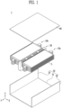
- FIG. 1 is a diagram for illustrating a battery module in accordance with an embodiment.
- a battery module 1 may include a plurality of cell stacks 10a, 10b and a partition wall 20.
- Each of the plurality of cell stacks 10a and 10b may include a plurality of battery cells 5.
- the plurality of battery cells 5 may be stacked in a vertical direction.
- the vertical direction may be in the Z axis direction.
- the plurality of battery cells 5 may be electrically connected to each other.
- the battery cell 5 may be a lithium ion battery, but this is only an example and may be various types of secondary batteries such as a lithium metal battery, a lithium sulfur battery, a solid-state battery, a lithium air battery,but is not limited thereto.
- the battery cell 5 may be a pouch-type battery, but this is only an example and may be transformed into various types of batteries such as prismatic and cylindrical.
- the plurality of cell stacks 10a, 10b may be spaced apart in a first horizontal direction.
- the first horizontal direction may be in the X-axis direction.
- the first horizontal direction may be a direction perpendicular to the vertical direction.
- the partition wall 20 may be disposed between the plurality of cell stacks 10a, 10b.
- the partition wall 20 may fix or support the plurality of cell stacks 10a, 10b.
- the battery module 1 may further include a module case.
- the module case may be a metal such as aluminum or iron, or an alloy of metal.
- the material of the module case may be modified into various materials including thermosetting resins.
- the material of the module case may be a single material composed of a thermosetting resin or a composite material further including other materials having special properties of the thermosetting resin.
- the special properties may be flame retardant, heat resistance, but is not limited thereto.
- Other materials may be, for example, carbon fiber, glass fiber, but is not limited thereto.
- the module case may include a lower case 50 and an upper case 60.
- the lower case 50 may include a lower cover 51 and side covers 52, 53.
- the lower cover 51 and the side covers 52, 53 may be integrally manufactured or individually manufactured and coupled using a method such as bolting or welding.
- the lower cover 51 may support the lower part of the plurality of cell stacks 10a, 10b.
- the side covers 52, 53 may support the sides of the plurality of cell stacks 10a, 10b.
- the side covers 52, 53 may be disposed to be spaced apart from each other and coupled to the lower cover 51.
- the side covers 52, 53 may be spaced apart in the first horizontal direction.
- the first horizontal direction may be in the X-axis direction.
- the side covers 52, 53 may be spaced apart in the second horizontal direction.
- the second horizontal direction may be in the Y-axis direction perpendicular to the X-axis direction.
- the lower case 50 may include a lower cover 51, side covers 52, 53 spaced apart in the first horizontal direction, and side covers spaced apart in the second horizontal direction.
- description will be made on the assumption that the first horizontal direction is the X-axis direction, the second horizontal direction is the Y-axis direction, and the vertical direction is the Z-axis direction.
- the upper case 60 may be disposed on the upper part of the plurality of cell stacks 10a and 10b.
- the battery module 1 may include a plate accommodated inside the partition wall 20.
- the battery module 1 may effectively discharge high-temperature gas generated from a specific battery cell to an external space through the partition wall 20 disposed between the plurality of cell stacks 10a, 10b and a plate accommodated inside the partition wall 20.
- the battery module 1 may minimize the transfer of high temperature gas or heat generated in a particular battery cell to another adjacent battery cell.
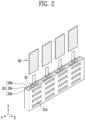
- FIG. 2 is a diagram for illustrating a partition wall and a plate in accordance with an embodiment.
- the partition wall 20 may include a side hole 21a.
- the side hole 21a may be formed on the side of the partition wall 20.
- the side hole 21a may be a hole penetrated in the first horizontal direction.
- the side hole 21a may be a passage through which gas generated from the battery cell inflows.
- the partition wall 20 may include a hollow 25.
- the hollow 25 may be formed inside the partition wall 20.
- the hollow 25 may be a hole penetrated in a vertical direction.
- the hollow 25 may be connected to the side hole 21a. Gas may inflow into the hollow 25 through the side hole 21a.
- the plate 30 may be inserted and accommodated in the hollow 25.
- the upper part of the hollow 25 may be connected to the external space.
- the hollow 25 may be a structure with an open upper part. The gas inflowing into the hollow 25 may be discharged to the external space through the upper part of the hollow 25.
- the partition wall 20 may include a plurality of side walls 20a, 20b.
- the plurality of side walls 20a, 20b may be disposed between the plurality of cell stacks.
- the plurality of cell stacks may be spaced apart from each other in the first horizontal direction.
- the plurality of side walls 20a, 20b may be spaced apart from each other in the first horizontal direction.
- the plurality of side walls 20a, 20b may include a first side wall 20a and a second side wall 20b.
- Each of the plurality of side walls 20a, 20b may include a side hole 21a.
- the hollow 25 may be formed between the plurality of side walls 20a, 20b.
- the side hole 21a may be connected to the hollow 25.
- the partition wall 20 may further include a plurality of connecting parts 20c.
- the plurality of connecting parts 20c may be spaced apart from each other in the second horizontal direction.
- the connecting part 20c may connect between the plurality of side walls 20a, 20b.
- the hollow 25 may be formed between the plurality of side walls 20a, 20b and the plurality of connecting parts 20c.
- the hollow 25 included in the partition wall 20 of the present disclosure may be one or plurality. In an embodiment, when there are a plurality of hollows 25, the plurality of hollows 25 may be spaced apart in the second horizontal direction.
- the plate 30 may be accommodated in the hollow 25.
- the plate 30 may be moved by the gas inflowing into the hollow 25 through the side hole 21a.
- the plate 30 may be moved to shield the side hole 21a through which the gas inflows and the opposite side hole.
- the plate 30 may be manufactured in a state accommodated in the partition wall 20 or may be manufactured separately from the partition wall 20 and then accommodated in the partition wall 20.
- the plate 30 may include an insulating material.
- the insulating material may be a material having thermal insulation properties due to its low thermal conductivity.
- the insulating material may include at least one material such as mica, silicate, glass fiber, mineral fiber,but is not limited thereto.
- the material of the partition wall 20 may be aluminum (e.g., Al50 series, Al60 series, etc.), stainless steel (e.g., SUS 303, SUS304, etc.), or a metal composite material including one or more insulating materials such as mica.
- the material of the partition wall 20 may be a composite resin material including glass fiber or carbon fiber. However, this is only an embodiment, and the material of the partition wall 20 may be modified and implemented with various materials.
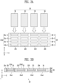
- FIGS. 3A and 3B are diagrams for illustrating a partition wall and a plate in detail in accordance with an embodiment.
- FIG. 3A is a side view of the partition wall
- FIG. 3B is a plan view of the partition wall.
- a plurality of plates 30 may be inserted and accommodated inside the partition wall 20.
- the partition wall 20 may include a plurality of side walls 20a, 20b and a plurality of connecting parts 20c.
- the plurality of side walls 20a, 20b may include a first side wall 20a and a second side wall 20b.
- the plurality of connecting parts 20c may be spaced apart in the second horizontal direction.
- the number of connecting parts 20c may be five.
- four hollows 251 ⁇ 254 may be formed between the first side wall 20a, the second side wall 20b, and the plurality of connecting parts 20c.
- the partition wall 20 may include a first hollow 251 to a fourth hollow 254.
- the plurality of hollows 251 ⁇ 254 may be spaced apart in the second horizontal direction.
- One plate 31 ⁇ 34 may be accommodated in each hollow 251 ⁇ 254.
- the plurality of hollows 251 ⁇ 254 may include first hollow 251 to fourth hollow 254.
- the first plate 31 may be accommodated in the first hollow 251
- the second plate 32 may be accommodated in the second hollow 252
- the third plate 33 may be accommodated in the third hollow 253
- the fourth plate 34 may be accommodated in the fourth hollow 254.
- each side wall 20a, 20b may be in contact with one cell stack.
- the first side wall 20a disposed between the first cell stack and the second cell stack may be in contact with the first cell stack.
- the second side wall 20b disposed between the first cell stack and the second cell stack may be in contact with the second cell stack.
- each of the plurality of side walls 20a, 20b may include a plurality of sub-areas 20-1 ⁇ 20-4 disposed in a vertical direction.
- One sub-area 20-1 ⁇ 20-4 may be an area in contact with one battery cell in one cell stack.
- the number of sub-areas 20-1 ⁇ 20-4 may be the same as the number in which battery cells are stacked.
- each of the side walls 20a, 20b may contact with the plurality of battery cells.
- Each side wall 20a, 20b may include a plurality of side holes 21a1, 21a2, 21b1, 21b2. At least one side hole 21a-1 ⁇ 21a-4 may be disposed in each sub-area 20-1 ⁇ 20-4. In other words, the number of side holes 21a-1 ⁇ 21a-4 disposed in one sub-area 20-1 ⁇ 20-4 may be one or plural.
- the plurality of side holes 21a1, 21a2, 21b1, 21b2 may be disposed on the first side wall 20a and the second side wall 20b according to rows and columns, respectively.
- the row may correspond to the vertical direction and the column may correspond to the second horizontal direction.
- the first side hole 21a-1 to the fourth side hole 21a-4 may be disposed in the first side wall 20a so that they are located in the same column.
- the plate 31 ⁇ 34 may have a size covering a side hole located in the same column among the plurality of side holes 21a1, 21a2, 21b1, and 21b2.
- the first plate 31 may be accommodated in the hollow 251 located in a first column of the first side wall 20a.
- the first plate 31 may have a size covering the first side hole 21a-1 to the fourth side hole 21a-4 located in the first column of the first side wall 20a.
- the width of the first plate 31 may be larger than the width of each of the first to fourth side holes 21a-1 ⁇ 21a-4.
- the width may be a length in the Y-axis direction.
- the height of the first plate 31 may be greater than the height from the first side hole 21a-1 to the fourth side hole 21a-4.
- the height may be a length in the Z-axis direction. Accordingly, the plate 30 can effectively shield the opposite side hole by gas inflowing through a specific side hole.
- one side hole of the plurality of side holes 21a1, 21a2, 21b1, and 21b2 may be connected to any one hollow of the plurality of hollows 251 ⁇ 254.
- the first side hole 21a-1 to the fourth side hole 21a-4 located in the first column of the first side wall 20a may be connected to the first hollow 251 located in a first column among the plurality of hollows 251 ⁇ 254.
- the side hole 21b1 located in a first column of the second side wall 20b may be connected to the first hollow 251 located in the first column.
- the side hole 21a2 located in a second column of the first side wall 20a may be connected to the second hollow 252 located in the second column
- the side hole 21b2 located in a second column of the second side wall 20b may be connected to the second hollow 252 located in the second column
- the plurality of connecting parts 20c may connect between the plurality of side walls 20a, 20b to form hollows 251 ⁇ 254.
- the cross section 25r of the connecting part 20c in the vertical direction may have a concave shape.
- the cross section 25r in the vertical direction may be a cross section of the XY plane perpendicular to the Z-axis direction.
- the length of the Y-axis of the connecting part 20c may increase.
- the length of the Y-axis of the connecting part 20c may increase.
- both ends of the cross section in the vertical direction of the hollows 251 ⁇ 254 may have a convex shape or a curved shape with curvature.
- Such a shape of the cross section 25r of the connecting part 20c or the shape of the cross section of the hollows 251 ⁇ 254 has a technical effect of facilitating the movement of the plate 30.
- the thickness of the hollow 251 ⁇ 254 may be larger than the thickness of the plate 30.
- the thickness may be a length in the X-axis direction. Accordingly, the plate 30 may be accommodated in the hollow 251 ⁇ 254.
- FIG. 4 is a diagram for illustrating a cell stack, a partition wall, and a plate in accordance with an embodiment.
- FIG. 4 shows a cross section of a battery module in which a cell stack, a partition wall, and a plate are disposed.
- the partition wall 20 may be disposed between the first cell stack 10a and the second cell stack 10b.
- the first cell stack 10a and the second cell stack 10b may be spaced apart from each other in the first horizontal direction.
- the first cell stack 10a may include a plurality of battery cells 5a-1, 5a-2 stacked in the vertical direction.
- the second cell stack 10b may include a plurality of battery cells 5b-1, 5b-2 stacked in the vertical direction.
- the partition wall 20 may include a first side wall 20a and a second side wall 20b.
- the first side wall 20a may be disposed such that the an outer side of the first side wall 20a contacts with the first cell stack 10a.
- the second side wall 20b may be disposed such that an outer side of the second side wall 20b contacts with the second cell stack 10b.
- the first side wall 20a may include a plurality of side holes 21a-1, 21a-2.
- the side hole 21a-1, 21a-2 of the first side wall 20a may be disposed in a vertical direction in a location corresponding to the battery cell 5a-1, 5a-2 of the first cell stack 10a within the first side wall 20a.
- the second side wall 20b may include a plurality of side holes 21b-1, 21b-2.
- the side hole 21b-1, 21b-2 of the second side wall 20b may be disposed in a vertical direction in a location corresponding to the battery cell 5b-1, 5b-2 of the second cell stack 10b within the second side wall 20b.
- the partition wall 20 may include a hollow 25 formed between the first side wall 20a and the second side wall 20b.
- the hollow 25 may be a space between the inner side of the first side wall 20a and the inner side of the second side wall 20b.
- the hollow 25 may accommodate the plate 30.
- the partition wall 20 may further include a bottom plate 27.
- the bottom plate 27 may support the plate 30 accommodated in the hollow 25.
- the bottom plate 27 may be omitted.
- FIG. 5 is a diagram for illustrating a location change of a plate in accordance with an embodiment.
- gas may be generated in a battery cell of any one cell stack of the first cell stack 10a and the second cell stack 10b.
- the gas may include at least one of carbon dioxide (CO2), carbon monoxide (CO), acetylene (C2H2), ethylene (C2H4), methane (CH4), hydrogen fluoride (HF), hydrogen (H2), but is not limited thereto.
- CO2 carbon dioxide
- CO carbon monoxide
- C2H2 acetylene
- CH4 methane
- HF hydrogen fluoride
- H2 hydrogen
- the gas generated in the second battery cell 5a-2 of the first cell stack 10a may inflow into the hollow 25 through the side hole 21a-2 of the first side wall 20a in contact with the second battery cell 5a-2.
- the plate 30 may be moved in the direction in which the gas inflows. In this case, the plate 30 may be moved toward the second side wall 20b, which is opposite to the first side wall 20a.
- the length La2 between the first side wall 20a and the plate 30 may become greater than the length Lb2 between the second side wall 20b and the plate 30 when gas inflows into the side hole 21a-2 of the first side wall 20a.
- the length Lb2 between the second side wall 20b and the plate 30 may be reduced to converge to zero.
- the length Lb2 between the second side wall 20b and the plate 30 after the gas inflows into the side hole 21a-2 of the first side wall 20a may become smaller than the length Lb1 between the second side wall 20b and the plate 30 before the gas inflows into the side hole 21a-2 of the first side wall 20a.
- the length La2 between the first side wall 20a and the plate 30 after the gas inflows into the side hole 21a-2 of the first side wall 20a may become greater than the length La1 between the first side wall 20a and the plate 30 before the gas inflows into the side hole 21a-2 of the first side wall 20a.
- the plate 30 may be moved to shield the side holes 21b-1 and 21b-2 disposed on the second side wall 20b.
- the side holes 21b-1, 21b-2 of the second side wall 20b are shielded by the plate 30, so that the connection between the side holes 21b-1, 21b-2 of the second side wall 20b and the hollow 25 may be blocked. Accordingly, propagation of the high temperature gas and heat generated in the second battery cell 5a-2 of the first cell stack 10a to the battery cells 5b-1, 5b-2 included in the second cell stack 10b may be minimized.
- the gas inflowing through the side hole 21a-2 may be discharged to the external space through the upper part of the hollow 25.
- the upper part of the hollow 25 may be connected to an external space.
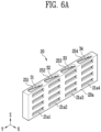
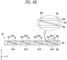
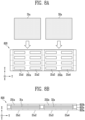
- FIGS. 6A and 6B are diagrams for illustrating an arrangement of plates in accordance with an embodiment.
- FIG. 6A is a perspective view of a partition wall in which a plate is accommodated
- FIG. 6B is a plan view of a partition wall in which a plate is accommodated.
- the partition wall 20 may include a plurality of hollows 251 ⁇ 254 and a plurality of side holes 21a1 ⁇ 21a4, 21b1 ⁇ 21b4.
- Each hollow 251 ⁇ 254 disposed between the first side wall 20a and the second side wall 20b may be connected to the side hole 21a1 ⁇ 21a4 of the first side wall 20a and the side hole 21b1 ⁇ 21b4 of the second side wall 20b.
- a plurality of plates 31 ⁇ 34 may be accommodated in a plurality of hollows 251 ⁇ 254, respectively.
- first side end 301 of each plate 31 ⁇ 34 may be coupled to the inner side of the first side wall 20a.
- the second side end 302 of each plate 31 ⁇ 34 may be coupled to the inner side of the second side wall 20b.
- the plate 30 may be coupled to each of the first side wall 20a and the second side wall 20b.
- the plate 30 may be manufactured in a state coupled to each of the first side wall 20a and the second side wall 20b.
- the plate 30 may be manufactured as an integral part together with the first side wall 20a and the second side wall 20b.
- the plate 30 may be of the same material as the first side wall 20a and the second side wall 20b.
- the plate 30 may be coupled to each of the first side wall 20a and the second side wall 20b using various methods such as adhesive or welding.
- the coupling surface may be broken so that the plate 30 may be separated from at least one of the first side wall 20a and the second side wall 20b. In this case, the plate 30 may be able to move by the inflowing gas.
- the partition wall 20 and the plate 30 may be manufactured as a single structure, or the partition wall 20 and the plate 30 may be manufactured as separate structures and assembled.
- the partition wall 20 and the plate 30 may be manufactured according to various manufacturing methods such as extrusion, casting, and cutting processing.
- FIGS. 7A and 7B are diagrams for illustrating a location change of a plate in accordance with an embodiment.
- gas generated in the battery cell may inflow through the side hole.
- gas is generated from the battery cell in contact with the first side wall 20a and inflows into the third side hole 21a3 of the first side wall 20a of the plurality of side holes 21a1 ⁇ 21a4, 21b1 ⁇ 21b4.
- a state before the gas inflows into the third side hole 21a3 may be the state shown in FIGS. 6A and 6B .
- the first side end 301 of each plate 31 ⁇ 34 may be attached to the inner side of the first side wall 20a.
- the second side end 302 of each plate 31 ⁇ 34 may be attached to the inner side of the second side wall 20b.
- the first side end 301 of the third plate 33 may be broken by the gas and separated from the inner side of the first side wall 20a.
- the third hollow 253 may be a hollow connected to the third side hole 21a3 among the plurality of hollows 251 ⁇ 254.
- the third plate 33 may be a plate accommodated in the third hollow 253 among the plurality of plates 31 ⁇ 34.
- the first side end 301 of the third plate 33 may be separated from the first side wall 20a. Meanwhile, when the pressure of the gas inflowing through the third side hole 21a3 is less than a reference value, the first side end 301 of the third plate 33 may remain coupled to the first side wall 20a without being separated from the first side wall 20a.
- the first side end 301 of the third plate 33 may be moved toward the second side wall 20b by the gas. Further, the third side hole 21b3 of the second side wall 20b may be shielded by the moved third plate 33. In other words, the third plate 33 may be moved in the direction in which the gas inflows. In this case, the third side hole 21b3 of the second side wall 20b may be shielded by the third plate 33 to prevent the heat of the gas from being transferred to the battery cell in contact with the second side wall 20b.
- the gas inflowing into the third hollow 253 through the third side hole 21a3 may be discharged to the external space through the upper part of the third hollow 253.
- the plates 31, 32, 34 accommodated in the hollows 251, 252, 254 connected to the remaining side holes 21a1, 21a2, 21a4 may remain fixed to the side walls 20a 20b.
- FIGS. 8A and 8B are diagrams for illustrating hollows and plates in accordance with an embodiment.
- FIG. 8A is a side view of a partition wall
- FIG. 8B is a plan view of a partition wall.
- the number of hollows 251a, 252a included in the partition wall 820 may be variously modified.
- the number and size of plates 31a, 32a may be variously modified and implemented.
- the number of hollows 251a, 252a may be the same as the number of plates 31a, 32a.
- the plate 31a, 32a may have a size that covers side holes corresponding to two columns.
- the first plate 31a may have a size including the side holes 21a1 of the first column and the side holes 21a2 of the second column.
- the second plate 32a may have a size including the side holes 21a3 of the third column and the side holes 21a4 of the fourth column.
- Each hollow 251a, 252a may have a size that may accommodate one plate 31a, 32a.
- the first hollow 251a may be connected to the side holes 21a1 of the first column and the side holes 21a2 of the second column.
- the second hollow 252a may be connected to the side holes 21a3 of the third column and the side holes 21a4 of the fourth column.
- FIGS. 9A and 9B are diagrams for illustrating hollows and plates in accordance with an embodiment.
- FIG. 9A is a side view of a partition wall
- Fig. 9B is a plan view of a partition wall.
- the number of plates 30b of the present disclosure may be one.
- the number of hollows 251b may be one.
- plate 30b may have a size that covers side holes corresponding to all columns.
- the plate 30b may have a size including the side holes 21a1 of the first column to the side holes 21a4 of the fourth column.
- the hollow 251b may have a size that may accommodate one plate 30b.
- the hollow 251b may be connected to the side holes 21a1 of the first column to the side holes 21a4 of the fourth column.
- FIG. 10 is a diagram for illustrating a battery module in accordance with an embodiment.
- the battery module 1 of the present disclosure may include three or more cell stacks 10a, 10b, 10c, a partition wall 20 disposed between the cell stacks 10a, 10b, 10c, and a plate 30 accommodated in the partition wall 20.
- the first cell stack 10a to the third cell stack 10c may be spaced apart in the first horizontal direction.
- the partition wall 20 may be disposed between the first cell stack 10a and the second cell stack 10b, and between the second cell stack 10b and the third cell stack 10c.
- the partition wall 20 may include a hollow in which the plate 30 is accommodated and a side hole formed on a side surface. Since it overlaps with the above description, a detailed description of the partition wall 20 and the plate 30 will be omitted.
- FIG. 10 is only one embodiment, and the number of cell stacks 10a, 10b, 10c and the partition walls 20 and the arrangement method accordingly may be variously modified and implemented.
Landscapes
- Chemical & Material Sciences (AREA)
- Chemical Kinetics & Catalysis (AREA)
- Electrochemistry (AREA)
- General Chemical & Material Sciences (AREA)
- Engineering & Computer Science (AREA)
- Manufacturing & Machinery (AREA)
- Battery Mounting, Suspending (AREA)
- Fuel Cell (AREA)
Abstract
Description
- The present disclosure relates to a secondary battery, and specifically, to a battery module and a manufacturing method thereof.
- As an energy source that drives various electronic devices such as smartphones, laptops, vehicles, and drones, the demand for secondary batteries is rapidly increasing.
- In particular, as a secondary battery for driving vehicles, research on battery modules to increase energy density is actively underway.
- The battery module may include a plurality of cell stacks in which multiple battery cells are stacked. The battery cell may represent the smallest unit of the battery.
- Meanwhile, for the battery module, there is a problem in that the structure of the battery module is deformed or destroyed due to an increase in internal pressure due to gas generated from a specific battery cell. In addition, there is a problem in that high-temperature gas and heat generated in a specific battery cell are propagated to other battery cells to accelerate fire or thermal propagation. Accordingly, a method of increasing the stability of the battery module is being sought.
- Embodiments provide a battery module in which the stability of battery cells is improved.
- In accordance with an aspect of the present disclosure, there is provided a battery module including a plurality of cell stacks spaced apart from each other in a horizontal direction, a plurality of side walls disposed between the plurality of cell stacks and spaced apart from each other in the horizontal direction, and a plate accommodated in a hollow between the plurality of side walls, Each of the plurality of side walls includes a side hole connected to the hollow.
- In an embodiment, the plate may be moved to shield a side hole of a second side wall of the plurality of side walls by gas inflowing into the hollow through a side hole of a first side wall of the plurality of side walls.
- In an embodiment, an upper part of the hollow may be connected to an external space, and the inflowing gas may be discharged to the external space through the upper part of the hollow.
- In an embodiment, a length between the first side wall and the plate may become greater than a length between the second side wall and the plate when the gas inflows into the side hole of the first side wall.
- In an embodiment, each of the plurality of cell stacks may include a plurality of battery cells stacked in a vertical direction.
- In an embodiment, each of the plurality of side walls may include a plurality of sub-areas disposed in the vertical direction, and each of the plurality of sub-areas may contact with one of the plurality of battery cells.
- In an embodiment, the side hole may be disposed in each of the plurality of sub-areas.
- In an embodiment, the battery module may further include a plurality of connecting parts configured to connect between the plurality of side walls to form the hollow.
- In an embodiment, a cross section in a vertical direction of each of the plurality of connecting parts may be concave.
- In an embodiment, a first side end of the plate may be coupled to an inside of a first side wall of the plurality of side walls, and a second side end of the plate is coupled to an inside of a second side wall of the plurality of side walls.
- In an embodiment, the first side end of the plate may be separated from the inside of the first side wall by gas inflowing into the hollow through a side hole of the first side wall and then moved to the inside of the second side wall. A side hole of the second side wall may be shielded by the plate.
- In an embodiment, the plate may include an insulating material.
- In accordance with another aspect of the present disclosure, there is provided a battery module including a first cell stack and a second cell stack spaced apart from each other in a first horizontal direction, a partition wall including a first side wall and a second side wall disposed between the first cell stack and the second cell stack, and a plurality of hollows disposed between the first side wall and the second side wall, and a plurality of plates, each of the plurality of plates being accommodated in each of the plurality of hollows. Each of the first side wall and the second side wall includes a plurality of side holes.
- In an embodiment, each of the plurality of side holes may be connected to any one hollow of the plurality of hollows.
- In an embodiment, the plurality of hollows may include a first hollow connected to a first side hole of the first side wall and a second side hole of the second side wall among the plurality of side holes, and a second hollow connected to a third side hole of the first side wall and a fourth side hole of the second side wall among the plurality of side holes.
- In an embodiment, the plurality of plates may include a first plate accommodated in the first hollow and a second plate accommodated in the second hollow.
- In an embodiment, the first plate may be moved to shield the second side hole when gas inflows into the first hollow through the first side hole.
- In an embodiment, the gas may be discharged to an external space through the first hollow.
- In an embodiment, the partition wall may further include a plurality of connecting parts spaced apart from each other in a second horizontal direction between the first side wall and the second side wall to form the plurality of hollows.
- In an embodiment, each of the first cell stack and the second cell stack may include a plurality of battery cells stacked in a vertical direction. The plurality of side holes may be disposed on each of the first side wall and the second side wall according to a row corresponding to the vertical direction and a column corresponding to the second horizontal direction. Each of the plurality of plates may have a size covering side holes located in the same column among the plurality of side holes.
- An embodiment of the present disclosure may provide a battery module in which the stability of battery cells is improved.
- An embodiment of the present disclosure may discharge a gas generated from a battery cell to an external space.
- An embodiment of the present disclosure may reduce the transfer of high temperature gas or heat generated in a battery cell to another battery cell.
- Example embodiments will now be described more fully hereinafter with reference to the accompanying drawings; however, they may be embodied in different forms and should not be construed as limited to the embodiments set forth herein. Rather, these embodiments are provided so that this disclosure will be thorough and complete, and will fully convey the scope of the example embodiments to those skilled in the art.
- In the drawing figures, dimensions may be exaggerated for clarity of illustration. It will be understood that when an element is referred to as being "between" two elements, it can be the only element between the two elements, or one or more intervening elements may also be present. Like reference numerals refer to like elements throughout.
-
FIG. 1 is a diagram for illustrating a battery module in accordance with an embodiment. -
FIG. 2 is a diagram for illustrating a partition wall and a plate in accordance with an embodiment. -
FIGS. 3A and 3B are diagrams for illustrating a partition wall and a plate in detail in accordance with an embodiment. -
FIG. 4 is a diagram for illustrating a cell stack, a partition wall, and a plate in accordance with an embodiment. -
FIG. 5 is a diagram for illustrating a location change of a plate in accordance with an embodiment. -
FIGS. 6A and6B are diagrams for illustrating an arrangement of plates in accordance with an embodiment. -
FIGS. 7A and 7B are diagrams for illustrating a location change of a plate in accordance with an embodiment. -
FIGS. 8A and 8B are diagrams for illustrating hollows and plates in accordance with an embodiment. -
FIGS. 9A and 9B are diagrams for illustrating hollows and plates in accordance with an embodiment. -
FIG. 10 is a diagram for illustrating a battery module in accordance with an embodiment. - The specific structural or functional description disclosed herein is merely illustrative for the purpose of describing embodiments according to the concept of the present disclosure, and the embodiments according to the concept of the present disclosure can be implemented in various forms, and cannot be construed as limited to the embodiments set forth herein.
-
FIG. 1 is a diagram for illustrating a battery module in accordance with an embodiment. - Referring to
FIG. 1 , abattery module 1 may include a plurality ofcell stacks partition wall 20. - Each of the plurality of
cell stacks battery cells 5. - The plurality of
battery cells 5 may be stacked in a vertical direction. For example, the vertical direction may be in the Z axis direction. The plurality ofbattery cells 5 may be electrically connected to each other. For example, thebattery cell 5 may be a lithium ion battery, but this is only an example and may be various types of secondary batteries such as a lithium metal battery, a lithium sulfur battery, a solid-state battery, a lithium air battery,but is not limited thereto. Thebattery cell 5 may be a pouch-type battery, but this is only an example and may be transformed into various types of batteries such as prismatic and cylindrical. - The plurality of
cell stacks - The
partition wall 20 may be disposed between the plurality ofcell stacks partition wall 20 may fix or support the plurality ofcell stacks - In an embodiment, the
battery module 1 may further include a module case. For example, the module case may be a metal such as aluminum or iron, or an alloy of metal. However, this is only an example, and the material of the module case may be modified into various materials including thermosetting resins. For a specific example, the material of the module case may be a single material composed of a thermosetting resin or a composite material further including other materials having special properties of the thermosetting resin. Here, the special properties may be flame retardant, heat resistance, but is not limited thereto. Other materials may be, for example, carbon fiber, glass fiber, but is not limited thereto. - The module case may include a
lower case 50 and anupper case 60. Thelower case 50 may include alower cover 51 and side covers 52, 53. Thelower cover 51 and the side covers 52, 53 may be integrally manufactured or individually manufactured and coupled using a method such as bolting or welding. - The
lower cover 51 may support the lower part of the plurality ofcell stacks - The side covers 52, 53 may support the sides of the plurality of
cell stacks lower cover 51. For example, the side covers 52, 53 may be spaced apart in the first horizontal direction. Here, the first horizontal direction may be in the X-axis direction. Meanwhile, unlike that shown inFIG. 1 , the side covers 52, 53 may be spaced apart in the second horizontal direction. Here, the second horizontal direction may be in the Y-axis direction perpendicular to the X-axis direction. In another embodiment, thelower case 50 may include alower cover 51, side covers 52, 53 spaced apart in the first horizontal direction, and side covers spaced apart in the second horizontal direction. Hereinafter, description will be made on the assumption that the first horizontal direction is the X-axis direction, the second horizontal direction is the Y-axis direction, and the vertical direction is the Z-axis direction. - The
upper case 60 may be disposed on the upper part of the plurality ofcell stacks - The
battery module 1 may include a plate accommodated inside thepartition wall 20. - The
battery module 1 according to an embodiment of the present disclosure may effectively discharge high-temperature gas generated from a specific battery cell to an external space through thepartition wall 20 disposed between the plurality ofcell stacks partition wall 20. In addition, thebattery module 1 may minimize the transfer of high temperature gas or heat generated in a particular battery cell to another adjacent battery cell. Hereinafter, the present disclosure will be described in more detail with reference to the accompanying drawings. -
FIG. 2 is a diagram for illustrating a partition wall and a plate in accordance with an embodiment. - Referring to
FIG. 2 , thepartition wall 20 may include aside hole 21a. Theside hole 21a may be formed on the side of thepartition wall 20. Theside hole 21a may be a hole penetrated in the first horizontal direction. Theside hole 21a may be a passage through which gas generated from the battery cell inflows. - The
partition wall 20 may include a hollow 25. The hollow 25 may be formed inside thepartition wall 20. The hollow 25 may be a hole penetrated in a vertical direction. The hollow 25 may be connected to theside hole 21a. Gas may inflow into the hollow 25 through theside hole 21a. Theplate 30 may be inserted and accommodated in the hollow 25. The upper part of the hollow 25 may be connected to the external space. In other words the hollow 25 may be a structure with an open upper part. The gas inflowing into the hollow 25 may be discharged to the external space through the upper part of the hollow 25. - In an embodiment, the
partition wall 20 may include a plurality ofside walls side walls side walls side walls first side wall 20a and asecond side wall 20b. - Each of the plurality of
side walls side hole 21a. The hollow 25 may be formed between the plurality ofside walls side hole 21a may be connected to the hollow 25. - In an embodiment, the
partition wall 20 may further include a plurality of connectingparts 20c. The plurality of connectingparts 20c may be spaced apart from each other in the second horizontal direction. The connectingpart 20c may connect between the plurality ofside walls side walls parts 20c. - In an embodiment, the hollow 25 included in the
partition wall 20 of the present disclosure may be one or plurality. In an embodiment, when there are a plurality ofhollows 25, the plurality ofhollows 25 may be spaced apart in the second horizontal direction. - The
plate 30 may be accommodated in the hollow 25. Theplate 30 may be moved by the gas inflowing into the hollow 25 through theside hole 21a. Theplate 30 may be moved to shield theside hole 21a through which the gas inflows and the opposite side hole. - Meanwhile, the
plate 30 may be manufactured in a state accommodated in thepartition wall 20 or may be manufactured separately from thepartition wall 20 and then accommodated in thepartition wall 20. - In an embodiment, the
plate 30 may include an insulating material. The insulating material may be a material having thermal insulation properties due to its low thermal conductivity. For example, the insulating material may include at least one material such as mica, silicate, glass fiber, mineral fiber,but is not limited thereto. - In an embodiment, the material of the
partition wall 20 may be aluminum (e.g., Al50 series, Al60 series, etc.), stainless steel (e.g., SUS 303, SUS304, etc.), or a metal composite material including one or more insulating materials such as mica. In an embodiment, the material of thepartition wall 20 may be a composite resin material including glass fiber or carbon fiber. However, this is only an embodiment, and the material of thepartition wall 20 may be modified and implemented with various materials. -
FIGS. 3A and 3B are diagrams for illustrating a partition wall and a plate in detail in accordance with an embodiment.FIG. 3A is a side view of the partition wall, andFIG. 3B is a plan view of the partition wall. - Referring to
FIGS. 3A and 3B , a plurality ofplates 30 may be inserted and accommodated inside thepartition wall 20. - In an embodiment, the
partition wall 20 may include a plurality ofside walls parts 20c. The plurality ofside walls first side wall 20a and asecond side wall 20b. The plurality of connectingparts 20c may be spaced apart in the second horizontal direction. For example, the number of connectingparts 20c may be five. In this case, fourhollows 251~254 may be formed between thefirst side wall 20a, thesecond side wall 20b, and the plurality of connectingparts 20c. In other words, thepartition wall 20 may include a first hollow 251 to a fourth hollow 254. - The plurality of
hollows 251~254 may be spaced apart in the second horizontal direction. Oneplate 31~34 may be accommodated in each hollow 251~254. For example, the plurality ofhollows 251~254 may include first hollow 251 to fourth hollow 254. In this case, thefirst plate 31 may be accommodated in the first hollow 251, thesecond plate 32 may be accommodated in the second hollow 252, thethird plate 33 may be accommodated in the third hollow 253, and thefourth plate 34 may be accommodated in the fourth hollow 254. - In an embodiment, each
side wall first side wall 20a disposed between the first cell stack and the second cell stack may be in contact with the first cell stack. Thesecond side wall 20b disposed between the first cell stack and the second cell stack may be in contact with the second cell stack. - Referring to
FIG. 3A , in an embodiment, each of the plurality ofside walls side walls - Each
side wall side hole 21a-1~21a-4 may be disposed in each sub-area 20-1~20-4. In other words, the number ofside holes 21a-1~21a-4 disposed in one sub-area 20-1~20-4 may be one or plural. - Referring to
FIGS. 3A and 3B , in an embodiment, the plurality of side holes 21a1, 21a2, 21b1, 21b2 may be disposed on thefirst side wall 20a and thesecond side wall 20b according to rows and columns, respectively. Here, the row may correspond to the vertical direction and the column may correspond to the second horizontal direction. For example, as shown inFIG. 3A , thefirst side hole 21a-1 to thefourth side hole 21a-4 may be disposed in thefirst side wall 20a so that they are located in the same column. - In this case, the
plate 31~34 may have a size covering a side hole located in the same column among the plurality of side holes 21a1, 21a2, 21b1, and 21b2. - Specifically, the
first plate 31 may be accommodated in the hollow 251 located in a first column of thefirst side wall 20a. In this case, thefirst plate 31 may have a size covering thefirst side hole 21a-1 to thefourth side hole 21a-4 located in the first column of thefirst side wall 20a. - For example, the width of the
first plate 31 may be larger than the width of each of the first to fourth side holes 21a-1~21a-4. Here, the width may be a length in the Y-axis direction. For example, the height of thefirst plate 31 may be greater than the height from thefirst side hole 21a-1 to thefourth side hole 21a-4. Here, the height may be a length in the Z-axis direction. Accordingly, theplate 30 can effectively shield the opposite side hole by gas inflowing through a specific side hole. - In an embodiment, one side hole of the plurality of side holes 21a1, 21a2, 21b1, and 21b2 may be connected to any one hollow of the plurality of
hollows 251~254. For example, thefirst side hole 21a-1 to thefourth side hole 21a-4 located in the first column of thefirst side wall 20a may be connected to the first hollow 251 located in a first column among the plurality ofhollows 251~254. Further, the side hole 21b1 located in a first column of thesecond side wall 20b may be connected to the first hollow 251 located in the first column. In the same manner, the side hole 21a2 located in a second column of thefirst side wall 20a may be connected to the second hollow 252 located in the second column, and the side hole 21b2 located in a second column of thesecond side wall 20b may be connected to the second hollow 252 located in the second column. - Referring to
FIG. 3B , in an embodiment, the plurality of connectingparts 20c may connect between the plurality ofside walls hollows 251~254. - In an embodiment, the
cross section 25r of the connectingpart 20c in the vertical direction may have a concave shape. Thecross section 25r in the vertical direction may be a cross section of the XY plane perpendicular to the Z-axis direction. For example, as the X-axis location of the connectingpart 20c is closer to thefirst side wall 20a from the center point of thefirst side wall 20a and thesecond side wall 20b, the length of the Y-axis of the connectingpart 20c may increase. For example, as the X-axis location of the connectingpart 20c is closer to thesecond side wall 20b from the center point of thefirst side wall 20a and thesecond side wall 20b, the length of the Y-axis of the connectingpart 20c may increase. In other words, both ends of the cross section in the vertical direction of thehollows 251~254 may have a convex shape or a curved shape with curvature. Such a shape of thecross section 25r of the connectingpart 20c or the shape of the cross section of thehollows 251~254 has a technical effect of facilitating the movement of theplate 30. - In an embodiment, the thickness of the hollow 251~254 may be larger than the thickness of the
plate 30. Here, the thickness may be a length in the X-axis direction. Accordingly, theplate 30 may be accommodated in the hollow 251~254. -
FIG. 4 is a diagram for illustrating a cell stack, a partition wall, and a plate in accordance with an embodiment.FIG. 4 shows a cross section of a battery module in which a cell stack, a partition wall, and a plate are disposed. - Referring to
FIG. 4 , thepartition wall 20 may be disposed between thefirst cell stack 10a and thesecond cell stack 10b. Thefirst cell stack 10a and thesecond cell stack 10b may be spaced apart from each other in the first horizontal direction. Thefirst cell stack 10a may include a plurality ofbattery cells 5a-1, 5a-2 stacked in the vertical direction. Thesecond cell stack 10b may include a plurality ofbattery cells 5b-1, 5b-2 stacked in the vertical direction. - The
partition wall 20 may include afirst side wall 20a and asecond side wall 20b. Thefirst side wall 20a may be disposed such that the an outer side of thefirst side wall 20a contacts with thefirst cell stack 10a. Thesecond side wall 20b may be disposed such that an outer side of thesecond side wall 20b contacts with thesecond cell stack 10b. - The
first side wall 20a may include a plurality ofside holes 21a-1, 21a-2. Theside hole 21a-1, 21a-2 of thefirst side wall 20a may be disposed in a vertical direction in a location corresponding to thebattery cell 5a-1, 5a-2 of thefirst cell stack 10a within thefirst side wall 20a. Thesecond side wall 20b may include a plurality ofside holes 21b-1, 21b-2. Theside hole 21b-1, 21b-2 of thesecond side wall 20b may be disposed in a vertical direction in a location corresponding to thebattery cell 5b-1, 5b-2 of thesecond cell stack 10b within thesecond side wall 20b. - The
partition wall 20 may include a hollow 25 formed between thefirst side wall 20a and thesecond side wall 20b. For example, the hollow 25 may be a space between the inner side of thefirst side wall 20a and the inner side of thesecond side wall 20b. The hollow 25 may accommodate theplate 30. - In an embodiment, the
partition wall 20 may further include abottom plate 27. Thebottom plate 27 may support theplate 30 accommodated in the hollow 25. In an embodiment, thebottom plate 27 may be omitted. -
FIG. 5 is a diagram for illustrating a location change of a plate in accordance with an embodiment. - Referring to
FIG. 5 , gas may be generated in a battery cell of any one cell stack of thefirst cell stack 10a and thesecond cell stack 10b. Here, the gas may include at least one of carbon dioxide (CO2), carbon monoxide (CO), acetylene (C2H2), ethylene (C2H4), methane (CH4), hydrogen fluoride (HF), hydrogen (H2), but is not limited thereto. However, this is only an example, and the components of the gas may be variously modified according to the electrolyte included in the battery cell. For example, the description will be made on the assumption that gas is generated in thesecond battery cell 5a-2 of thefirst cell stack 10a. - In this case, the gas generated in the
second battery cell 5a-2 of thefirst cell stack 10a may inflow into the hollow 25 through theside hole 21a-2 of thefirst side wall 20a in contact with thesecond battery cell 5a-2. - Then, by the pressure of the gas inflowing into the hollow 25 through the
side hole 21a-2 of thefirst side wall 20a, theplate 30 may be moved in the direction in which the gas inflows. In this case, theplate 30 may be moved toward thesecond side wall 20b, which is opposite to thefirst side wall 20a. - In an embodiment, the length La2 between the
first side wall 20a and theplate 30 may become greater than the length Lb2 between thesecond side wall 20b and theplate 30 when gas inflows into theside hole 21a-2 of thefirst side wall 20a. - Here, when gas inflows into the
side hole 21a-2 of thefirst side wall 20a, the length Lb2 between thesecond side wall 20b and theplate 30 may be reduced to converge to zero. For example, referring toFIGS. 4 and 5 , the length Lb2 between thesecond side wall 20b and theplate 30 after the gas inflows into theside hole 21a-2 of thefirst side wall 20a may become smaller than the length Lb1 between thesecond side wall 20b and theplate 30 before the gas inflows into theside hole 21a-2 of thefirst side wall 20a. Meanwhile, the length La2 between thefirst side wall 20a and theplate 30 after the gas inflows into theside hole 21a-2 of thefirst side wall 20a may become greater than the length La1 between thefirst side wall 20a and theplate 30 before the gas inflows into theside hole 21a-2 of thefirst side wall 20a. - In other words, when gas inflows through one
side hole 21a-2 of the side holes 21a-1 and 21a-2 disposed on thefirst side wall 20a, theplate 30 may be moved to shield the side holes 21b-1 and 21b-2 disposed on thesecond side wall 20b. In this case, the side holes 21b-1, 21b-2 of thesecond side wall 20b are shielded by theplate 30, so that the connection between the side holes 21b-1, 21b-2 of thesecond side wall 20b and the hollow 25 may be blocked. Accordingly, propagation of the high temperature gas and heat generated in thesecond battery cell 5a-2 of thefirst cell stack 10a to thebattery cells 5b-1, 5b-2 included in thesecond cell stack 10b may be minimized. - In addition, the gas inflowing through the
side hole 21a-2 may be discharged to the external space through the upper part of the hollow 25. Here, the upper part of the hollow 25 may be connected to an external space. -
FIGS. 6A and6B are diagrams for illustrating an arrangement of plates in accordance with an embodiment.FIG. 6A is a perspective view of a partition wall in which a plate is accommodated, andFIG. 6B is a plan view of a partition wall in which a plate is accommodated. - Referring to
FIGS. 6A and6B , thepartition wall 20 may include a plurality ofhollows 251~254 and a plurality of side holes 21a1~21a4, 21b1~21b4. Each hollow 251~254 disposed between thefirst side wall 20a and thesecond side wall 20b may be connected to the side hole 21a1~21a4 of thefirst side wall 20a and the side hole 21b1~21b4 of thesecond side wall 20b. A plurality ofplates 31~34 may be accommodated in a plurality ofhollows 251~254, respectively. - In an embodiment, the
first side end 301 of eachplate 31~34 may be coupled to the inner side of thefirst side wall 20a. Thesecond side end 302 of eachplate 31~34 may be coupled to the inner side of thesecond side wall 20b. In other words, theplate 30 may be coupled to each of thefirst side wall 20a and thesecond side wall 20b. For example, theplate 30 may be manufactured in a state coupled to each of thefirst side wall 20a and thesecond side wall 20b. In other words, theplate 30 may be manufactured as an integral part together with thefirst side wall 20a and thesecond side wall 20b. In this case, theplate 30 may be of the same material as thefirst side wall 20a and thesecond side wall 20b. For another example, after theplate 30 and thefirst side wall 20a and thesecond side wall 20b are manufactured as individual parts, theplate 30 may be coupled to each of thefirst side wall 20a and thesecond side wall 20b using various methods such as adhesive or welding. - In an embodiment, when the pressure of the gas inflowing through the side hole 21a1~21a4, 21b1~21b4 in a state where the
plate 30 is coupled to thefirst side wall 20a and thesecond side wall 20b, respectively, is greater than the reference value, the coupling surface may be broken so that theplate 30 may be separated from at least one of thefirst side wall 20a and thesecond side wall 20b. In this case, theplate 30 may be able to move by the inflowing gas. - In an embodiment, the
partition wall 20 and theplate 30 may be manufactured as a single structure, or thepartition wall 20 and theplate 30 may be manufactured as separate structures and assembled. For example, thepartition wall 20 and theplate 30 may be manufactured according to various manufacturing methods such as extrusion, casting, and cutting processing. -
FIGS. 7A and 7B are diagrams for illustrating a location change of a plate in accordance with an embodiment. - Referring to
FIGS. 7A and 7B , gas generated in the battery cell may inflow through the side hole. Hereinafter, it is assumed that gas is generated from the battery cell in contact with thefirst side wall 20a and inflows into the third side hole 21a3 of thefirst side wall 20a of the plurality of side holes 21a1~21a4, 21b1~21b4. - Here, a state before the gas inflows into the third side hole 21a3 may be the state shown in
FIGS. 6A and6B . In other words, thefirst side end 301 of eachplate 31~34 may be attached to the inner side of thefirst side wall 20a. Thesecond side end 302 of eachplate 31~34 may be attached to the inner side of thesecond side wall 20b. - In an embodiment, when gas inflows into the third hollow 253 through the third side hole 21a3 of the
first side wall 20a, thefirst side end 301 of thethird plate 33 may be broken by the gas and separated from the inner side of thefirst side wall 20a. The third hollow 253 may be a hollow connected to the third side hole 21a3 among the plurality ofhollows 251~254. Thethird plate 33 may be a plate accommodated in the third hollow 253 among the plurality ofplates 31~34. - For example, when the pressure of the gas inflowing through the third side hole 21a3 is greater than or equal to a reference value, the
first side end 301 of thethird plate 33 may be separated from thefirst side wall 20a. Meanwhile, when the pressure of the gas inflowing through the third side hole 21a3 is less than a reference value, thefirst side end 301 of thethird plate 33 may remain coupled to thefirst side wall 20a without being separated from thefirst side wall 20a. - Further, after the
first side end 301 of thethird plate 33 is separated by the gas, thefirst side end 301 of thethird plate 33 may be moved toward thesecond side wall 20b by the gas. Further, the third side hole 21b3 of thesecond side wall 20b may be shielded by the movedthird plate 33. In other words, thethird plate 33 may be moved in the direction in which the gas inflows. In this case, the third side hole 21b3 of thesecond side wall 20b may be shielded by thethird plate 33 to prevent the heat of the gas from being transferred to the battery cell in contact with thesecond side wall 20b. - In this case, the gas inflowing into the third hollow 253 through the third side hole 21a3 may be discharged to the external space through the upper part of the third hollow 253.
- In an embodiment, when gas does not inflow into the remaining side holes 21a1, 21a2, 21a4 other than the third side hole 21a3, or the pressure of the inflowing gas is less than a reference value, the
plates hollows side walls 20a -
FIGS. 8A and 8B are diagrams for illustrating hollows and plates in accordance with an embodiment.FIG. 8A is a side view of a partition wall, andFIG. 8B is a plan view of a partition wall. - Referring to
FIGS. 8A and 8B , the number of hollows 251a, 252a included in thepartition wall 820 may be variously modified. The number and size ofplates plates - In an embodiment, the
plate first plate 31a may have a size including the side holes 21a1 of the first column and the side holes 21a2 of the second column. Thesecond plate 32a may have a size including the side holes 21a3 of the third column and the side holes 21a4 of the fourth column. - Each hollow 251a, 252a may have a size that may accommodate one
plate -
FIGS. 9A and 9B are diagrams for illustrating hollows and plates in accordance with an embodiment.FIG. 9A is a side view of a partition wall, andFig. 9B is a plan view of a partition wall. - Referring to
FIGS. 9A and 9B , the number ofplates 30b of the present disclosure may be one. In this case, the number ofhollows 251b may be one. - In an embodiment,
plate 30b may have a size that covers side holes corresponding to all columns. For example, theplate 30b may have a size including the side holes 21a1 of the first column to the side holes 21a4 of the fourth column. - The hollow 251b may have a size that may accommodate one
plate 30b. In this case, the hollow 251b may be connected to the side holes 21a1 of the first column to the side holes 21a4 of the fourth column. -
FIG. 10 is a diagram for illustrating a battery module in accordance with an embodiment. - Referring to
FIG. 10 , thebattery module 1 of the present disclosure may include three ormore cell stacks partition wall 20 disposed between thecell stacks plate 30 accommodated in thepartition wall 20. - For example, the
first cell stack 10a to thethird cell stack 10c may be spaced apart in the first horizontal direction. In this case, thepartition wall 20 may be disposed between thefirst cell stack 10a and thesecond cell stack 10b, and between thesecond cell stack 10b and thethird cell stack 10c. Thepartition wall 20 may include a hollow in which theplate 30 is accommodated and a side hole formed on a side surface. Since it overlaps with the above description, a detailed description of thepartition wall 20 and theplate 30 will be omitted. - Meanwhile, the embodiment shown in
FIG. 10 is only one embodiment, and the number ofcell stacks partition walls 20 and the arrangement method accordingly may be variously modified and implemented. - While the present disclosure has been shown and described with reference to certain exemplary embodiments thereof, it will be understood by those skilled in the art that various changes in form and details may be made therein without departing from the spirit and scope of the present disclosure as defined by the appended claims and their equivalents. Therefore, the scope of the present disclosure should not be limited to the above-described exemplary embodiments but should be determined by not only the appended claims but also the equivalents thereof.
- In the above-described embodiments, all steps may be selectively performed or part of the steps and may be omitted. In each embodiment, the steps are not necessarily performed in accordance with the described order and may be rearranged. The embodiments disclosed in this specification and drawings are only examples to facilitate an understanding of the present disclosure, and the present disclosure is not limited thereto. That is, it should be apparent to those skilled in the art that various modifications can be made on the basis of the technological scope of the present disclosure.
- Meanwhile, the exemplary embodiments of the present disclosure have been described in the drawings and specification. Although specific terminologies are used here, those are only to explain the embodiments of the present disclosure. Therefore, the present disclosure is not restricted to the above-described embodiments and many variations are possible within the spirit and scope of the present disclosure. It should be apparent to those skilled in the art that various modifications can be made on the basis of the technological scope of the present disclosure in addition to the embodiments disclosed herein.
Claims (15)
- A battery module comprising:a plurality of cell stacks spaced apart from each other in a horizontal direction;a plurality of side walls disposed between the plurality of cell stacks and spaced apart from each other in the horizontal direction; anda plate accommodated in a hollow between the plurality of side walls,wherein each of the plurality of side walls comprises a side hole connected to the hollow.
- The battery module of claim 1, wherein the plate is moved to shield a side hole of a second side wall of the plurality of side walls by gas inflowing into the hollow through a side hole of a first side wall of the plurality of side walls.
- The battery module of claim 2, wherein an upper part of the hollow is connected to an external space, and
the inflowing gas is discharged to the external space through the upper part of the hollow. - The battery module of claim 2 or 3, wherein a length between the first side wall and the plate becomes greater than a length between the second side wall and the plate when the gas inflows into the side hole of the first side wall.
- The battery module of anyone of the preceding claims, wherein each of the plurality of cell stacks comprises a plurality of battery cells stacked in a vertical direction
- The battery module of anyone of the preceding claims, wherein each of the plurality of side walls comprises a plurality of sub-areas disposed in the vertical direction, andeach of the plurality of sub-areas contacts with one of the plurality of battery cells,preferably wherein the side hole is disposed in each of the plurality of sub-areas.
- The battery module of anyone of the preceding claims, further comprising:a plurality of connecting parts configured to connect between the plurality of side walls to form the hollow,preferably wherein a cross section in a vertical direction of each of the plurality of connecting parts is concave .
- The battery module of anyone of the preceding claims, wherein a first side end of the plate is coupled to an inside of a first side wall of the plurality of side walls, and a second side end of the plate is coupled to an inside of a second side wall of the plurality of side walls.
- The battery module of claim 8, wherein the first side end of the plate is separated from the inside of the first side wall by gas inflowing into the hollow through a side hole of the first side wall and then moved to the inside of the second side wall, anda side hole of the second side wall is shielded by the plate,preferably wherein the plate comprises an insulating material.
- A battery module comprising:a first cell stack and a second cell stack spaced apart from each other in a first horizontal direction;a partition wall comprising a first side wall and a second side wall disposed between the first cell stack and the second cell stack, and a plurality of hollows disposed between the first side wall and the second side wall; anda plurality of plates, each of the plurality of plates being accommodated in each of the plurality of hollows,wherein each of the first side wall and the second side wall comprises a plurality of side holes.
- The battery module of claim 10, wherein each of the plurality of side holes is connected to any one hollow of the plurality of hollows.
- The battery module of claim 10 or 11, wherein the plurality of hollows comprise a first hollow connected to a first side hole of the first side wall and a second side hole of the second side wall among the plurality of side holes, and a second hollow connected to a third side hole of the first side wall and a fourth side hole of the second side wall among the plurality of side holes.
- The battery module of anyone of the claims 10 to 12, wherein the plurality of plates comprise a first plate accommodated in the first hollow and a second plate accommodated in the second hollow,preferably wherein the first plate is moved to shield the second side hole when gas inflows into the first hollow through the first side hole, and/orpreferably wherein the gas is discharged to an external space through the first hollow.
- The battery module of anyone of claims 10 to 13,
wherein the partition wall further comprises a plurality of connecting parts spaced apart from each other in a second horizontal direction between the first side wall and the second side wall to form the plurality of hollows. - The battery module of anyone of claims 10 to 14, wherein each of the first cell stack and the second cell stack comprises a plurality of battery cells stacked in a vertical direction,the plurality of side holes are disposed on each of the first side wall and the second side wall according to a row corresponding to the vertical direction and a column corresponding to the second horizontal direction, andeach of the plurality of plates has a size covering side holes located in the same column among the plurality of side holes.
Applications Claiming Priority (1)
| Application Number | Priority Date | Filing Date | Title |
|---|---|---|---|
| KR1020220121785A KR20240042920A (en) | 2022-09-26 | 2022-09-26 | Battery module |
Publications (2)
| Publication Number | Publication Date |
|---|---|
| EP4343906A1 true EP4343906A1 (en) | 2024-03-27 |
| EP4343906B1 EP4343906B1 (en) | 2025-07-30 |
Family
ID=85703787
Family Applications (1)
| Application Number | Title | Priority Date | Filing Date |
|---|---|---|---|
| EP23161959.4A Active EP4343906B1 (en) | 2022-09-26 | 2023-03-15 | Battery module |
Country Status (4)
| Country | Link |
|---|---|
| US (1) | US12603360B2 (en) |
| EP (1) | EP4343906B1 (en) |
| KR (1) | KR20240042920A (en) |
| CN (1) | CN117766941A (en) |
Cited By (1)
| Publication number | Priority date | Publication date | Assignee | Title |
|---|---|---|---|---|
| DE102023121374A1 (en) | 2023-08-10 | 2025-02-13 | Audi Aktiengesellschaft | Gas discharge chamber, battery arrangement and method for discharging gases escaping from a battery cell |
Families Citing this family (3)
| Publication number | Priority date | Publication date | Assignee | Title |
|---|---|---|---|---|
| KR20250176856A (en) * | 2024-06-13 | 2025-12-22 | 주식회사 엘지에너지솔루션 | Battery device |
| GB2642713A (en) * | 2024-07-18 | 2026-01-21 | Jaguar Land Rover Ltd | Vehicle battery enclosure |
| GB2642714A (en) * | 2024-07-18 | 2026-01-21 | Jaguar Land Rover Ltd | Vehicle battery enclosure |
Citations (3)
| Publication number | Priority date | Publication date | Assignee | Title |
|---|---|---|---|---|
| US20130040174A1 (en) * | 2010-11-30 | 2013-02-14 | Hiroshi Takasaki | Battery pack |
| EP3926747A1 (en) * | 2019-11-08 | 2021-12-22 | Contemporary Amperex Technology Co., Limited | Battery pack and apparatus |
| EP4019094A1 (en) * | 2019-11-07 | 2022-06-29 | Lg Energy Solution, Ltd. | Battery module, battery rack, and power storage device |
Family Cites Families (4)
| Publication number | Priority date | Publication date | Assignee | Title |
|---|---|---|---|---|
| KR102270234B1 (en) | 2017-12-12 | 2021-06-25 | 주식회사 엘지에너지솔루션 | Battery module embedding cross beam and Battery pack comprising the battery module |
| EP3731300A4 (en) * | 2017-12-19 | 2021-03-10 | SANYO Electric Co., Ltd. | POWER SUPPLY DEVICE AND POWER SUPPLY DEVICE SEPARATOR |
| KR102802106B1 (en) | 2020-07-28 | 2025-05-02 | 에스케이온 주식회사 | Battery pack |
| KR102953580B1 (en) * | 2020-08-26 | 2026-04-15 | 주식회사 엘지에너지솔루션 | Large battery module and a bettery pack including the same |
-
2022
- 2022-09-26 KR KR1020220121785A patent/KR20240042920A/en active Pending
-
2023
- 2023-03-13 US US18/182,367 patent/US12603360B2/en active Active
- 2023-03-14 CN CN202310238837.9A patent/CN117766941A/en active Pending
- 2023-03-15 EP EP23161959.4A patent/EP4343906B1/en active Active
Patent Citations (3)
| Publication number | Priority date | Publication date | Assignee | Title |
|---|---|---|---|---|
| US20130040174A1 (en) * | 2010-11-30 | 2013-02-14 | Hiroshi Takasaki | Battery pack |
| EP4019094A1 (en) * | 2019-11-07 | 2022-06-29 | Lg Energy Solution, Ltd. | Battery module, battery rack, and power storage device |
| EP3926747A1 (en) * | 2019-11-08 | 2021-12-22 | Contemporary Amperex Technology Co., Limited | Battery pack and apparatus |
Cited By (1)
| Publication number | Priority date | Publication date | Assignee | Title |
|---|---|---|---|---|
| DE102023121374A1 (en) | 2023-08-10 | 2025-02-13 | Audi Aktiengesellschaft | Gas discharge chamber, battery arrangement and method for discharging gases escaping from a battery cell |
Also Published As
| Publication number | Publication date |
|---|---|
| KR20240042920A (en) | 2024-04-02 |
| CN117766941A (en) | 2024-03-26 |
| US20240106031A1 (en) | 2024-03-28 |
| EP4343906B1 (en) | 2025-07-30 |
| US12603360B2 (en) | 2026-04-14 |
Similar Documents
| Publication | Publication Date | Title |
|---|---|---|
| EP4343906B1 (en) | Battery module | |
| US11637339B2 (en) | Battery module | |
| KR101314454B1 (en) | Battery pack | |
| US9112202B2 (en) | Battery module | |
| KR100684766B1 (en) | Secondary battery module | |
| KR101708366B1 (en) | Battery module | |
| US20120115011A1 (en) | Battery module having battery cell holder | |
| CN108604653A (en) | Battery pack | |
| US12142786B2 (en) | Battery module and battery pack | |
| WO2020140643A1 (en) | Battery pack and vehicle | |
| JPWO2020070773A1 (en) | Battery module and battery pack | |
| KR20070018507A (en) | Secondary battery module | |
| US20240204289A1 (en) | Battery assembly and battery pack including battery assembly | |
| CN218351630U (en) | Battery module, battery pack, electric device and equipment for manufacturing battery module | |
| KR20250019302A (en) | Battery pack | |
| US20240322302A1 (en) | Battery cell, battery, electric apparatus, and preparation method and apparatus of battery cell | |
| US20260106329A1 (en) | Battery apparatus and method for manufacturing battery apparatus | |
| US20260058245A1 (en) | Battery assembly | |
| US20250253452A1 (en) | Battery assembly | |
| US20260088431A1 (en) | Battery Cell Assembly | |
| CN222775353U (en) | Battery module and lithium ion battery | |
| US20250349931A1 (en) | Battery assembly | |
| CN222530709U (en) | Support frame for energy storage device and energy storage device | |
| JP2007109547A (en) | Cooling structure | |
| US20260135228A1 (en) | Battery Module and Battery Pack Including the Same |
Legal Events
| Date | Code | Title | Description |
|---|---|---|---|
| PUAI | Public reference made under article 153(3) epc to a published international application that has entered the european phase |
Free format text: ORIGINAL CODE: 0009012 |
|
| STAA | Information on the status of an ep patent application or granted ep patent |
Free format text: STATUS: REQUEST FOR EXAMINATION WAS MADE |
|
| 17P | Request for examination filed |
Effective date: 20230315 |
|
| AK | Designated contracting states |
Kind code of ref document: A1 Designated state(s): AL AT BE BG CH CY CZ DE DK EE ES FI FR GB GR HR HU IE IS IT LI LT LU LV MC ME MK MT NL NO PL PT RO RS SE SI SK SM TR |
|
| GRAP | Despatch of communication of intention to grant a patent |
Free format text: ORIGINAL CODE: EPIDOSNIGR1 |
|
| STAA | Information on the status of an ep patent application or granted ep patent |
Free format text: STATUS: GRANT OF PATENT IS INTENDED |
|
| INTG | Intention to grant announced |
Effective date: 20250331 |
|
| RIC1 | Information provided on ipc code assigned before grant |
Ipc: H01M 50/367 20210101ALI20250321BHEP Ipc: H01M 50/209 20210101ALI20250321BHEP Ipc: H01M 50/463 20210101ALI20250321BHEP Ipc: H01M 50/35 20210101ALI20250321BHEP Ipc: H01M 50/24 20210101ALI20250321BHEP Ipc: H01M 10/04 20060101AFI20250321BHEP |
|
| RIN1 | Information on inventor provided before grant (corrected) |
Inventor name: LEE, SEUNG DONG Inventor name: JEON, HAE RYONG Inventor name: JEONG, WON SEOK |
|
| GRAS | Grant fee paid |
Free format text: ORIGINAL CODE: EPIDOSNIGR3 |
|
| GRAA | (expected) grant |
Free format text: ORIGINAL CODE: 0009210 |
|
| STAA | Information on the status of an ep patent application or granted ep patent |
Free format text: STATUS: THE PATENT HAS BEEN GRANTED |
|
| AK | Designated contracting states |
Kind code of ref document: B1 Designated state(s): AL AT BE BG CH CY CZ DE DK EE ES FI FR GB GR HR HU IE IS IT LI LT LU LV MC ME MK MT NL NO PL PT RO RS SE SI SK SM TR |
|
| REG | Reference to a national code |
Ref country code: GB Ref legal event code: FG4D |
|
| REG | Reference to a national code |
Ref country code: CH Ref legal event code: EP |
|
| REG | Reference to a national code |
Ref country code: DE Ref legal event code: R096 Ref document number: 602023005109 Country of ref document: DE |
|
| REG | Reference to a national code |
Ref country code: IE Ref legal event code: FG4D |
|
| REG | Reference to a national code |
Ref country code: NL Ref legal event code: MP Effective date: 20250730 |
|
| REG | Reference to a national code |
Ref country code: AT Ref legal event code: MK05 Ref document number: 1820042 Country of ref document: AT Kind code of ref document: T Effective date: 20250730 |
|
| PG25 | Lapsed in a contracting state [announced via postgrant information from national office to epo] |
Ref country code: PT Free format text: LAPSE BECAUSE OF FAILURE TO SUBMIT A TRANSLATION OF THE DESCRIPTION OR TO PAY THE FEE WITHIN THE PRESCRIBED TIME-LIMIT Effective date: 20251202 |
|
| PG25 | Lapsed in a contracting state [announced via postgrant information from national office to epo] |
Ref country code: IS Free format text: LAPSE BECAUSE OF FAILURE TO SUBMIT A TRANSLATION OF THE DESCRIPTION OR TO PAY THE FEE WITHIN THE PRESCRIBED TIME-LIMIT Effective date: 20251130 |
|
| PG25 | Lapsed in a contracting state [announced via postgrant information from national office to epo] |
Ref country code: NO Free format text: LAPSE BECAUSE OF FAILURE TO SUBMIT A TRANSLATION OF THE DESCRIPTION OR TO PAY THE FEE WITHIN THE PRESCRIBED TIME-LIMIT Effective date: 20251030 |
|
| REG | Reference to a national code |
Ref country code: LT Ref legal event code: MG9D |
|
| PG25 | Lapsed in a contracting state [announced via postgrant information from national office to epo] |
Ref country code: AT Free format text: LAPSE BECAUSE OF FAILURE TO SUBMIT A TRANSLATION OF THE DESCRIPTION OR TO PAY THE FEE WITHIN THE PRESCRIBED TIME-LIMIT Effective date: 20250730 |
|
| PG25 | Lapsed in a contracting state [announced via postgrant information from national office to epo] |
Ref country code: FI Free format text: LAPSE BECAUSE OF FAILURE TO SUBMIT A TRANSLATION OF THE DESCRIPTION OR TO PAY THE FEE WITHIN THE PRESCRIBED TIME-LIMIT Effective date: 20250730 |
|
| PG25 | Lapsed in a contracting state [announced via postgrant information from national office to epo] |
Ref country code: HR Free format text: LAPSE BECAUSE OF FAILURE TO SUBMIT A TRANSLATION OF THE DESCRIPTION OR TO PAY THE FEE WITHIN THE PRESCRIBED TIME-LIMIT Effective date: 20250730 Ref country code: NL Free format text: LAPSE BECAUSE OF FAILURE TO SUBMIT A TRANSLATION OF THE DESCRIPTION OR TO PAY THE FEE WITHIN THE PRESCRIBED TIME-LIMIT Effective date: 20250730 |
|
| PGFP | Annual fee paid to national office [announced via postgrant information from national office to epo] |
Ref country code: FR Payment date: 20251223 Year of fee payment: 4 |
|
| PG25 | Lapsed in a contracting state [announced via postgrant information from national office to epo] |
Ref country code: GR Free format text: LAPSE BECAUSE OF FAILURE TO SUBMIT A TRANSLATION OF THE DESCRIPTION OR TO PAY THE FEE WITHIN THE PRESCRIBED TIME-LIMIT Effective date: 20251031 |
|
| PG25 | Lapsed in a contracting state [announced via postgrant information from national office to epo] |
Ref country code: SE Free format text: LAPSE BECAUSE OF FAILURE TO SUBMIT A TRANSLATION OF THE DESCRIPTION OR TO PAY THE FEE WITHIN THE PRESCRIBED TIME-LIMIT Effective date: 20250730 |
|
| PG25 | Lapsed in a contracting state [announced via postgrant information from national office to epo] |
Ref country code: LV Free format text: LAPSE BECAUSE OF FAILURE TO SUBMIT A TRANSLATION OF THE DESCRIPTION OR TO PAY THE FEE WITHIN THE PRESCRIBED TIME-LIMIT Effective date: 20250730 |
|
| PG25 | Lapsed in a contracting state [announced via postgrant information from national office to epo] |
Ref country code: PL Free format text: LAPSE BECAUSE OF FAILURE TO SUBMIT A TRANSLATION OF THE DESCRIPTION OR TO PAY THE FEE WITHIN THE PRESCRIBED TIME-LIMIT Effective date: 20250730 Ref country code: BG Free format text: LAPSE BECAUSE OF FAILURE TO SUBMIT A TRANSLATION OF THE DESCRIPTION OR TO PAY THE FEE WITHIN THE PRESCRIBED TIME-LIMIT Effective date: 20250730 |
|
| PG25 | Lapsed in a contracting state [announced via postgrant information from national office to epo] |
Ref country code: RS Free format text: LAPSE BECAUSE OF FAILURE TO SUBMIT A TRANSLATION OF THE DESCRIPTION OR TO PAY THE FEE WITHIN THE PRESCRIBED TIME-LIMIT Effective date: 20251030 |
|
| PG25 | Lapsed in a contracting state [announced via postgrant information from national office to epo] |
Ref country code: ES Free format text: LAPSE BECAUSE OF FAILURE TO SUBMIT A TRANSLATION OF THE DESCRIPTION OR TO PAY THE FEE WITHIN THE PRESCRIBED TIME-LIMIT Effective date: 20250730 |
|
| PG25 | Lapsed in a contracting state [announced via postgrant information from national office to epo] |
Ref country code: SM Free format text: LAPSE BECAUSE OF FAILURE TO SUBMIT A TRANSLATION OF THE DESCRIPTION OR TO PAY THE FEE WITHIN THE PRESCRIBED TIME-LIMIT Effective date: 20250730 |
|
| PG25 | Lapsed in a contracting state [announced via postgrant information from national office to epo] |
Ref country code: DK Free format text: LAPSE BECAUSE OF FAILURE TO SUBMIT A TRANSLATION OF THE DESCRIPTION OR TO PAY THE FEE WITHIN THE PRESCRIBED TIME-LIMIT Effective date: 20250730 |
|
| PGFP | Annual fee paid to national office [announced via postgrant information from national office to epo] |
Ref country code: DE Payment date: 20251222 Year of fee payment: 4 |
|
| PG25 | Lapsed in a contracting state [announced via postgrant information from national office to epo] |
Ref country code: IT Free format text: LAPSE BECAUSE OF FAILURE TO SUBMIT A TRANSLATION OF THE DESCRIPTION OR TO PAY THE FEE WITHIN THE PRESCRIBED TIME-LIMIT Effective date: 20250730 |
|
| PG25 | Lapsed in a contracting state [announced via postgrant information from national office to epo] |
Ref country code: CZ Free format text: LAPSE BECAUSE OF FAILURE TO SUBMIT A TRANSLATION OF THE DESCRIPTION OR TO PAY THE FEE WITHIN THE PRESCRIBED TIME-LIMIT Effective date: 20250730 |
|
| PG25 | Lapsed in a contracting state [announced via postgrant information from national office to epo] |
Ref country code: EE Free format text: LAPSE BECAUSE OF FAILURE TO SUBMIT A TRANSLATION OF THE DESCRIPTION OR TO PAY THE FEE WITHIN THE PRESCRIBED TIME-LIMIT Effective date: 20250730 Ref country code: SK Free format text: LAPSE BECAUSE OF FAILURE TO SUBMIT A TRANSLATION OF THE DESCRIPTION OR TO PAY THE FEE WITHIN THE PRESCRIBED TIME-LIMIT Effective date: 20250730 |