EP4343884A1 - Battery pole piece material removing apparatus and battery pole piece material removing method - Google Patents
Battery pole piece material removing apparatus and battery pole piece material removing method Download PDFInfo
- Publication number
- EP4343884A1 EP4343884A1 EP22831782.2A EP22831782A EP4343884A1 EP 4343884 A1 EP4343884 A1 EP 4343884A1 EP 22831782 A EP22831782 A EP 22831782A EP 4343884 A1 EP4343884 A1 EP 4343884A1
- Authority
- EP
- European Patent Office
- Prior art keywords
- battery electrode
- electrode plate
- coating material
- current collector
- predetermined region
- Prior art date
- Legal status (The legal status is an assumption and is not a legal conclusion. Google has not performed a legal analysis and makes no representation as to the accuracy of the status listed.)
- Granted
Links
Images


Classifications
-
- B—PERFORMING OPERATIONS; TRANSPORTING
- B05—SPRAYING OR ATOMISING IN GENERAL; APPLYING FLUENT MATERIALS TO SURFACES, IN GENERAL
- B05B—SPRAYING APPARATUS; ATOMISING APPARATUS; NOZZLES
- B05B13/00—Machines or plants for applying liquids or other fluent materials to surfaces of objects or other work by spraying, not covered by groups B05B1/00 - B05B11/00
- B05B13/02—Means for supporting work; Arrangement or mounting of spray heads; Adaptation or arrangement of means for feeding work
-
- H—ELECTRICITY
- H01—ELECTRIC ELEMENTS
- H01M—PROCESSES OR MEANS, e.g. BATTERIES, FOR THE DIRECT CONVERSION OF CHEMICAL ENERGY INTO ELECTRICAL ENERGY
- H01M4/00—Electrodes
- H01M4/02—Electrodes composed of, or comprising, active material
- H01M4/13—Electrodes for accumulators with non-aqueous electrolyte, e.g. for lithium-accumulators; Processes of manufacture thereof
- H01M4/139—Processes of manufacture
-
- B—PERFORMING OPERATIONS; TRANSPORTING
- B05—SPRAYING OR ATOMISING IN GENERAL; APPLYING FLUENT MATERIALS TO SURFACES, IN GENERAL
- B05B—SPRAYING APPARATUS; ATOMISING APPARATUS; NOZZLES
- B05B14/00—Arrangements for collecting, re-using or eliminating excess spraying material
- B05B14/30—Arrangements for collecting, re-using or eliminating excess spraying material comprising enclosures close to, or in contact with, the object to be sprayed and surrounding or confining the discharged spray or jet but not the object to be sprayed
-
- B—PERFORMING OPERATIONS; TRANSPORTING
- B05—SPRAYING OR ATOMISING IN GENERAL; APPLYING FLUENT MATERIALS TO SURFACES, IN GENERAL
- B05C—APPARATUS FOR APPLYING FLUENT MATERIALS TO SURFACES, IN GENERAL
- B05C5/00—Apparatus in which liquid or other fluent material is projected, poured or allowed to flow on to the surface of the work
- B05C5/02—Apparatus in which liquid or other fluent material is projected, poured or allowed to flow on to the surface of the work the liquid or other fluent material being discharged through an outlet orifice by pressure, e.g. from an outlet device in contact or almost in contact, with the work
-
- H—ELECTRICITY
- H01—ELECTRIC ELEMENTS
- H01M—PROCESSES OR MEANS, e.g. BATTERIES, FOR THE DIRECT CONVERSION OF CHEMICAL ENERGY INTO ELECTRICAL ENERGY
- H01M10/00—Secondary cells; Manufacture thereof
- H01M10/05—Accumulators with non-aqueous electrolyte
- H01M10/052—Li-accumulators
- H01M10/0525—Rocking-chair batteries, i.e. batteries with lithium insertion or intercalation in both electrodes; Lithium-ion batteries
-
- H—ELECTRICITY
- H01—ELECTRIC ELEMENTS
- H01M—PROCESSES OR MEANS, e.g. BATTERIES, FOR THE DIRECT CONVERSION OF CHEMICAL ENERGY INTO ELECTRICAL ENERGY
- H01M10/00—Secondary cells; Manufacture thereof
- H01M10/05—Accumulators with non-aqueous electrolyte
- H01M10/058—Construction or manufacture
-
- H—ELECTRICITY
- H01—ELECTRIC ELEMENTS
- H01M—PROCESSES OR MEANS, e.g. BATTERIES, FOR THE DIRECT CONVERSION OF CHEMICAL ENERGY INTO ELECTRICAL ENERGY
- H01M4/00—Electrodes
- H01M4/02—Electrodes composed of, or comprising, active material
- H01M4/04—Processes of manufacture in general
-
- H—ELECTRICITY
- H01—ELECTRIC ELEMENTS
- H01M—PROCESSES OR MEANS, e.g. BATTERIES, FOR THE DIRECT CONVERSION OF CHEMICAL ENERGY INTO ELECTRICAL ENERGY
- H01M4/00—Electrodes
- H01M4/02—Electrodes composed of, or comprising, active material
- H01M4/04—Processes of manufacture in general
- H01M4/0402—Methods of deposition of the material
- H01M4/0404—Methods of deposition of the material by coating on electrode collectors
-
- H—ELECTRICITY
- H01—ELECTRIC ELEMENTS
- H01M—PROCESSES OR MEANS, e.g. BATTERIES, FOR THE DIRECT CONVERSION OF CHEMICAL ENERGY INTO ELECTRICAL ENERGY
- H01M50/00—Constructional details or processes of manufacture of the non-active parts of electrochemical cells other than fuel cells, e.g. hybrid cells
- H01M50/50—Current conducting connections for cells or batteries
- H01M50/531—Electrode connections inside a battery casing
-
- H—ELECTRICITY
- H01—ELECTRIC ELEMENTS
- H01M—PROCESSES OR MEANS, e.g. BATTERIES, FOR THE DIRECT CONVERSION OF CHEMICAL ENERGY INTO ELECTRICAL ENERGY
- H01M50/00—Constructional details or processes of manufacture of the non-active parts of electrochemical cells other than fuel cells, e.g. hybrid cells
- H01M50/50—Current conducting connections for cells or batteries
- H01M50/531—Electrode connections inside a battery casing
- H01M50/536—Electrode connections inside a battery casing characterised by the method of fixing the leads to the electrodes, e.g. by welding
-
- Y—GENERAL TAGGING OF NEW TECHNOLOGICAL DEVELOPMENTS; GENERAL TAGGING OF CROSS-SECTIONAL TECHNOLOGIES SPANNING OVER SEVERAL SECTIONS OF THE IPC; TECHNICAL SUBJECTS COVERED BY FORMER USPC CROSS-REFERENCE ART COLLECTIONS [XRACs] AND DIGESTS
- Y02—TECHNOLOGIES OR APPLICATIONS FOR MITIGATION OR ADAPTATION AGAINST CLIMATE CHANGE
- Y02E—REDUCTION OF GREENHOUSE GAS [GHG] EMISSIONS, RELATED TO ENERGY GENERATION, TRANSMISSION OR DISTRIBUTION
- Y02E60/00—Enabling technologies; Technologies with a potential or indirect contribution to GHG emissions mitigation
- Y02E60/10—Energy storage using batteries
Definitions
- the present disclosure relates to preparation of a battery electrode plate, and particularly to a material removal device and method for a battery electrode plate.
- the improvement of energy density of lithium-ion batteries has always been the focus of attention.
- the improvement of energy density of lithium-ion batteries not only can be achieved from the perspective of the inherent properties of battery materials, but also can be achieved from the perspective of the structure of lithium-ion batteries.
- the position of the tab on the battery electrode plate in the lithium-ion battery begins to change from the position at the end of the electrode plate at the early stage to the middle position of the electrode plate, i.e., the coating area of the battery electrode plate.
- the change of the position of the tab means the change of the preparation method of the battery electrode plate.
- the tab is located in the coating area of the battery electrode plate. In the presence of an electrode coating, the tab cannot be soldered to the current collector of the electrode. Therefore, it is necessary to remove the coating material corresponding to the tab from the coating area first.
- methods commonly used for removing the coating material include a mechanical scraping cleaning method, a chemical cleaning method, and a laser cleaning method.
- a mechanical scraping cleaning method because a metal scraper is used to directly contact the surface of current collector, certain production risks are caused.
- the gap between the scraper and the battery electrode plate is too large, the residual coating is difficult to clean.
- the chemical cleaning method causes certain pollution to the environment, and has the problems such as poor working environment and low production efficiency.
- the laser cleaning method due to the uneven distribution of laser energy, the battery electrode plate is likely to be damaged, and the surface of the electrode plate is easily oxidized, resulting in reduced strength. Therefore, it is necessary to adopt a better method to remove the coating material in a specific region on the battery electrode plate.
- the present disclosure provides a material removal device and method for a battery electrode plate.
- the material removal device for a battery electrode plate to remove materials, the coating material at the position where the tab needs to be soldered on the battery electrode plate can be efficiently and effectively removed, thereby greatly reducing the degree of damage to the current collector and the residue of the coating material on the current collector after removal.
- the present application provides a material removal device for a battery electrode plate.
- the battery electrode plate includes a current collector and a coating material attached to a surface of the current collector.
- the material removal device for a battery electrode plate is configured to remove the coating material of a predetermined region of the battery electrode plate, and includes a positioning member, a spraying port, and a suction port.
- the positioning member includes a side plate.
- a hollow space is defined by the side plate.
- the side plate is configured to be in contact with the current collector to isolate the coating material of the predetermined region in the hollow space.
- the spraying port is located in the hollow space, and configured to be in communication with a liquid source to spray a liquid onto the coating material of the predetermined region, so that fluidity of the coating material of the predetermined region is increased by the liquid.
- the suction port is located in the hollow space and configured to be in communication with a vacuum generation device to suck the coating material of the predetermined region away from the current collector.
- the positioning member further includes a top plate, the side plate is arranged at a periphery of the top plate, and the side plate is configured to be in contact with the current collector to seal the hollow space.
- the suction port has a suction port surface enclosing a channel in communication with the hollow space, and the suction port surface is at least partially of a bell shape having an opening facing the hollow space.
- the side plate includes an inner side plate and an outer side plate, the inner side plate and the outer side plate are spaced apart to form a suction pipe, the suction pipe is in communication with the suction port, and one end of the outer side plate close to the battery electrode plate is configured to be in contact with the current collector.
- the side plate includes an inner side plate and an outer side plate
- the top plate includes an inner top plate and an outer top plate
- the inner side plate is connected to the inner top plate to form an inner wall of a suction pipe
- the outer side plate is connected to the outer top plate to form an outer wall of the suction pipe
- the inner wall of the suction pipe and the outer wall of the suction pipe form the suction pipe
- the suction pipe is in communication with the suction port
- one end of the outer side plate close to the battery electrode plate is configured to be in contact with the current collector to seal the hollow space.
- one end of the suction pipe close to the battery electrode plate forms the suction port.
- the end of the inner side plate close to the battery electrode plate is configured to be in contact with a surface of the coating material of the predetermined region away from the current collector.
- a main spraying pipe is arranged in the top plate, the main spraying pipe is formed with the spraying port on one side of the top plate close to the battery electrode plate, and the spraying port is in communication with the liquid source through the main spraying pipe to spray the liquid on the coating material of the predetermined region.
- the material removal device for a battery electrode plate further includes a spraying plate, the spraying plate being arranged in the hollow space, a plurality of spraying pipes in communication with the main spraying pipe being arranged in the spraying plate, and the spraying port being formed on one side of the plurality of spraying pipes away from the main spraying pipe.
- the material removal device for a battery electrode plate of the present disclosure can accurately remove the coating material of the predetermined region used for soldering the tab on the battery electrode plate.
- the positioning member included in the device can lock the predetermined region requiring removal of the coating material.
- the contact of the side plate in the positioning member with the current collector can separate the predetermined region requiring removal of the coating material from a non-predetermined region not requiring removal of the coating material. In this way, the coating material of the non-predetermined region is not removed during removal of the coating material of the predetermined region, thereby improving the precision of material removal.
- the material removal device for a battery electrode plate further includes the spraying port.
- the spraying port is in communication with the liquid source to spray the liquid on the predetermined region separated by the positioning member, so as to reduce the viscosity of the coating material of the predetermined region and facilitate the suction of the coating material in this region.
- the material removal device for a battery electrode plate further includes the suction port.
- the suction port can suck the low-viscosity coating material of the predetermined region away from the current collector. Compared with the mechanical scraping cleaning method, the chemical cleaning method, and the laser cleaning method in the related art, the suction of the coating material can greatly reduce the damage to the battery electrode plate and the residue of the coating material on the current collector, thereby improving the soldering yield of the tab on the current collector.
- the material removal device for a battery electrode plate integrates the positioning member having positioning and isolation functions, the spraying port having a liquid spraying function, and the suction port having a coating material suction function, so that the coating material of the predetermined region of the battery electrode plate can be conveniently, quickly and efficiently removed, thereby improving the production efficiency of the battery electrode plate.
- the present application provides a material removal method for a battery electrode plate, for removing a coating material of a predetermined region of a battery electrode plate by using the material removal device for a battery electrode plate, and including the following steps:
- the method further includes: spraying the liquid on the current collector from which the coating material has been sucked away, and at the same time sucking the liquid away from the current collector through the suction port.
- the method further includes: drying the battery electrode plate.
- a standard for liquid spraying is to spray 1 to 3 g of the liquid per square centimeter of the predetermined region.
- the suction port is connected to a vacuum generation device, and a vacuum degree of the vacuum generation device is 50 to 300 KPa.
- the coating material at the position where the tab needs to be arranged can be removed conveniently, quickly and effectively, to facilitate the soldering of the tab on the current collector, thereby improving the soldering yield of the tab.
- battery electrode plate 1 current collector 11, coating material 12, tab 13, predetermined region 14, material removal device 100 for battery electrode plate, positioning member 2, side plate 21, inner side plate 211, outer side plate 212, hollow space 22, top plate 23, inner top plate 231, outer top plate 232, spraying port 3, suction port 4, suction pipe 5, main spraying pipe 6, spraying plate 7, spraying pipe 8, channel 41 of suction port in communication with hollow space, suction port surface 42; beam 213.
- a lithium-ion battery includes a battery electrode plate.
- the battery electrode plate 1 includes a current collector 11, a coating material 12 attached to a surface of the current collector 11, and a tab 13 soldered to the current collector 11.
- an end of the current collector 11 is a blank current collector configured for soldering the tab 13, and the other part of the current collector 11 is configured for coating the coating material 12.
- the path of electron transmission to the external circuit is longer, and some heat is generated in the process of electron transmission, resulting in a loss of battery capacity and affecting the improvement of battery energy density.
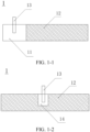
- the position of the tab 13 on the battery electrode plate 1 may be changed. As shown in FIG. 1-2 , the position of the tab 13 is changed from the end of the current collector 11 to the middle portion of the current collector 11 or near the middle portion of the current collector 11, so that the path for transmission of electrons between the battery electrode plate 1 and the external circuit can be shortened, thereby reducing the loss of battery energy density caused by electron transmission, and improving the battery energy density. Because the tab 13 cannot be directly soldered to the coating material 12, the coating material 12 at the position where the tab is soldered needs to be removed to expose the current collector 11, so that the current collector 11 and the tab 13 can be soldered together.
- the present application provides a material removal device 100 for a battery electrode plate, which is configured to remove the coating material 12 of a predetermined region 14 of the battery electrode plate.
- the predetermined region 14 is a region for soldering the tab 13.
- the material removal device 100 for a battery electrode plate includes a positioning member 2, a spraying port 3, and a suction port 4.
- the positioning member 2 includes a side plate 21. A space formed by the side plate 21 is defined as a hollow space 22.
- the side plate 21 is configured to be in contact with the current collector 11 to isolate the coating material of the predetermined region 14 in the hollow space 22.
- the contact of the side plate 21 with the current collector 11 is that the side plate 21 runs through the coating material 12 to come into contact with the current collector 11.
- the spraying port 3 is arranged in the hollow space 22.
- the spraying port 3 is configured to be in communication with a liquid source to spray a liquid onto the coating material of the predetermined region 14, so that fluidity of the coating material of the predetermined region 14 is increased by the liquid.
- the suction port 4 is located in the hollow space 22.
- the suction port 4 is configured to be in communication with a vacuum generation device to suck the coating material of the predetermined region 14 away from the current collector 11.
- the coating material of the predetermined region 14 can be accurately removed without affecting the coating material not to be removed, thereby improving the precision of material removal. Furthermore, the suction port 4 arranged in the hollow space 22 only sucks the coating material of the predetermined region 14 isolated in the hollow space 22 away from the current collector 11, and does not affect the coating material that is outside the hollow space 22 and does not need to be removed, so as not to affect the subsequent usage effect of the battery electrode plate 1.
- the suction port 4 is located in the coating material 12, and a distance between a portion of the suction port 4 away from the side plate 21 and the current collector 11 is greater than a distance between a portion of the suction port 4 close to the side plate 21 and the current collector 11.
- a plane where a feeding position of the suction port 4 lies is not parallel to, but forms an angle with the current collector 11.
- such a configuration can increase the feeding amount at the feeding position, i.e., facilitate the feeding of the coating material to the suction port.
- the positioning member 2 further includes a top plate 23, the side plate 21 is arranged at a periphery of the top plate 23 to form the hollow space 22, and the side plate 21 is configured to be in contact with the current collector 11 to seal the hollow space 22.
- the top plate 23 and the side plate 21 form the hollow space 22 having an opening at one end.
- the current collector 11 can seal the opening, and the coating material 12 of the predetermined region 14 is also isolated at the opening.
- a suction pipe 5 is arranged in the side plate 21.
- the suction pipe 5 is formed with a first discharge port on a side of the side plate 21 close to the battery electrode plate 1.
- the suction pipe 5 is formed with a second discharge port on a side of the side plate away from the battery electrode plate 1.
- the first discharge port is in communication with the suction port 4.
- the second discharge port is configured to be in communication with the vacuum generation device. Under the action of the vacuum generation device, the coating material of the predetermined region 14 is sucked away from the current collector 11 through the suction port 4 and the suction pipe 5.
- a suction pipe 5 is arranged in the side plate 21, the side plate 21 includes an inner side plate 211 adjacent to the hollow space 22 and an outer side plate 212 away from the hollow space 22, and the inner side plate 211 and the outer side plate 212 are spaced apart to form the suction pipe 5.
- the inner side plate 211 and the outer side plate 212 are spaced apart by a distance.
- the hollow space 22 is defined by the outer side plate 212.
- the inner side plate 211 is arranged in the hollow space 22 around the outer side plate 212.
- a beam 213 is arranged at one end of the inner side plate 211 and the outer side plate 212 away from the battery electrode plate 1.
- the beam 213 is configured to connect the inner side plate 211 and the outer side plate 212.
- a space defined by the inner side plate 211, the outer side plate 212, and the beam 213 and having an opening at each of two ends is the suction pipe 5. Arrows in the suction pipe 5 in the figures represent a direction in which the coating material is sucked away.
- the suction pipe 5 is formed with a second discharge port on the beam 213.
- the second discharge port is configured to be in communication with the vacuum generation device.
- the suction pipe 5 is formed with a first discharge port at one end thereof close to the battery electrode plate 1, i.e., at a position where the inner side plate 211 can come into contact with the coating material 12.
- the first discharge port is the suction port 4.
- an end of the inner side plate 211 close to the battery electrode plate 1 and an end of the outer side plate 212 close to the battery electrode plate 1 together form the suction port 4.
- the openings of the suction pipe 5 defined by the inner side plate 211, the outer side plate 212, and the beam 213 are the second discharge ports.
- the end of the outer side plate 212 close to the battery electrode plate 1 is configured to be in contact with the current collector 11 to isolate the coating material of the predetermined region 14 in the hollow space 22.
- the end of the inner side plate 211 close to the battery electrode plate 1 is configured to be in contact with a surface of the coating material 12 of the predetermined region 14 away from the current collector.
- the outer side plate 212 is not even with the inner side plate 211 are not flush, but instead, the outer side plate 212 protrudes from the inner side plate 211.
- the positioning member 2 is used for positioning the coating material of the predetermined region 14, the outer side plate 212 is in contact with the current collector 11.
- the inner side plate 211 is short and cannot come into contact with the current collector 11, but can come into contact with the coating material 12.
- the inner side plate may be in contact with the surface of the coating layer away from the current collector 11, or may be inserted into the coating layer to come into contact with the coating material, as long as the inner side plate is not in contact with the current collector 11.
- the inner side plate 211 is in contact with the surface of the coating layer.
- the suction port 4 at the end of the side plate 21 close to the battery electrode plate 1 by designing a height difference between the inner side plate 211 and the outer side plate 212, no suction port 4 needs to be separately provided in the hollow space 22, thereby reducing the number of components and simplifying the device configuration.
- the inner side plate 211 is not in contact with the current collector 11 and is only in contact with the coating material 12, the coating material can be effectively sucked away from the surface of the current collector.
- the contact of the inner side plate 211 with the surface of the coating material 12 allows for a sufficiently large area of the suction port 4, so that the coating material 12 can be efficiently and rapidly sucked away.
- the feeding amount can be increased, i.e., the feeding of the coating material to the suction port is facilitated.
- the top plate 23 and the side plate 21 are both provided with a suction pipe 5.
- the suction pipe 5 includes an inner wall and an outer wall.
- the side plate 21 includes an inner side plate 211 adjacent to the hollow space 22 and an outer side plate 212 away from the hollow space 22.
- the top plate 23 includes an inner top plate 231 close to the hollow space 22 and an outer top plate 232 away from the hollow space 22.
- the inner side plate 211 and the inner top plate 231 are connected to form the inner wall of the suction pipe 5.
- the outer side plate 212 and the outer top plate 232 are connected to form the outer wall of the suction pipe 5.
- the suction pipe 5 and the suction port 4 are in communication with the vacuum generation device through the suction pipe 5 to suck the coating material 12 of the predetermined region 14 away from the current collector 11.
- a main spraying pipe 6 is arranged in the top plate, and the material removal device for a battery electrode plate further includes a spraying plate 7.
- the spraying plate 7 is arranged in the hollow space 22.
- a plurality of spraying pipes 8 in communication with the main spraying pipe 6 are arranged in the spraying plate 7.
- the spraying port 3 is formed on one side of the plurality of spraying pipes 8 away from the main spraying pipe 6.
- the spraying port 3 is in communication with the liquid source through the main spraying pipe 6 and the plurality of spraying pipes 8 to spray the liquid on the coating material of the predetermined region 14.
- the spraying plate 7 is opposite to the battery electrode plate 1, and the spraying port 3 is located on a side of the spraying plate 7 close to the battery electrode plate 1.
- the spraying plate 7 is provided with a plurality of spraying ports 3.
- the spraying plate 7 is similar to a shower head in daily life and has a plurality of spraying ports 3, so that the spraying efficiency can be improved.
- the spraying plate 7 is preferably arranged in parallel with the battery electrode plate 1, so that the liquid sprayed from the spraying plate 7 can be directly sprayed on the coating material of the predetermined region 14. In this way, all the coating material 12 in the predetermined region 14 can quickly come into contact with the sprayed liquid, thereby improving the efficiency of wetting the coating material of the predetermined region 14.
- a main spraying pipe 6 is arranged in the top plate 23, the main spraying pipe 6 is formed with the spraying port 3 on one side of the top plate 23 close to the battery electrode plate 1, and the spraying port 3 is in communication with the liquid source through the main spraying pipe 6 to spray the liquid on the coating material of the predetermined region 14.
- the side plate 21 is in contact with the current collector 11 of the battery electrode plate, and the shape and size of the region defined by the side plate 21 on the battery electrode plate 1 are determined by the pre-designed shape and size of the coating material to be removed from the battery electrode plate.
- the tab 13 soldered to the current collector 11 includes a tab body and a tab adhesive. One portion of the tab body is soldered to the current collector 11, and the other portion of the tab body extends beyond the current collector 11. The portion of the tab body soldered to the current collector 11 is usually rectangular, so the region defined by the side plate 21 on the battery electrode plate 1 is rectangular in shape. An area of the region defined is larger than an area of the portion of the tab body soldered to the current collector.
- the present application further provides a material removal method for a battery electrode plate, for removing a coating material of a predetermined region of a battery electrode plate by using the material removal device for a battery electrode plate.
- the method includes the following steps.
- the arrangement of the side plate 21 allows for the separate isolation of the predetermined region 14, so that the coating material to be removed and the coating material not to be removed can be separated from each other, to prevent the removal of the coating material to be removed from interfering with the coating material not to be removed to lead to the removal of the coating material not to be removed and result in a failure of electrode plate preparation. Therefore, the skillful design and use of the side plate 21 improves the accuracy of removing the coating material of the predetermined region of the battery electrode plate, and improves the yield of preparation of the battery electrode plate.
- the side plate 21 in step (1) has separated the coating material of the predetermined region 14, the liquid sprayed from the spraying port 3 does not come into contact with the coating material outside the predetermined region, and only the coating material of the predetermined region 14 can come into contact with the liquid.
- the liquid wets the coating material of the predetermined region 14, to reduce the viscosity of the coating material and increase the fluidity of the coating material of the predetermined region 14, thereby facilitating suction and removal.
- step (4) may further be performed to clean the predetermined region 14.
- step (3) the spraying procedure is started again to distribute the liquid sprayed from the spraying port 3 onto the current collector in the predetermined region 14, and a suction program is started at the same time to suck away the liquid on the current collector 11 in the predetermined region 14, thereby realizing the cleaning of the predetermined region 14.
- Arrows in the figure respectively represent a direction in which the liquid is sprayed and a direction in which the liquid is sucked away.
- step (4) After the cleaning in step (4) is completed, it can be ensured that the coating material of the predetermined region 14 has been all removed, and the surface of the current collector in the predetermined region can be sufficiently clean to facilitate soldering of the tab.
- a standard for liquid spraying is to spray 1 to 3 g of the liquid per square centimeter of the predetermined region.
- a vacuum degree of the vacuum generation device is 50 to 300 KPa.
- a standard for liquid spraying is to spray 1 to 3 g of the liquid per square centimeter of the predetermined region, and a vacuum degree of the vacuum generation device is 50 to 300 KPa.
- the battery electrode plate 1 is a battery electrode plate whose surface coating material is not dried.
- the undried coating material can be more easily wet by the liquid sprayed from the spraying port, and more easily sucked away.
- the battery electrode plate may be dried.
- the liquid is an organic solvent.
- the organic solvent is selected from at least one of an ester solvent or an ether solvent.
- the ester solvent is selected from at least one of vinyl carbonate, propylene carbonate, dimethyl carbonate, diethyl carbonate, methyl ethyl carbonate, ethyl acetate, methyl acetate, ethyl propionate, methyl propionate, propyl propionate, or butyrolactone.
- the ether solvent is selected from at least one of ether, tetrahydrofuran, or furan.
- This embodiment is an embodiment of assembly of a lithium-ion battery.
- the current collector was an aluminum foil
- the coating material was a positive electrode active slurry.
- Lithium cobaltate, conductive carbon, and PVDF were mixed in NMP (N-methyl-2-pyrrolidone) at a mass ratio of 97:1.5:1.5, and uniformly mixed by mechanical stirring to prepare the slurry.
- NMP N-methyl-2-pyrrolidone
- the viscosity of the positive electrode active slurry was 5000cp, and the solid content of the slurry was 80%.
- Preparation of positive electrode plate The positive electrode active slurry was coated on the aluminum foil. The obtained areal density was 14 mg/cm 2 .
- Removal of coating material of the predetermined region The coating material of the predetermined region of the positive electrode plate was removed by using the material removal device for a battery electrode plate according to the present application.
- the positioning member was moved, so that the side plate passed through the coating layer and came into contact with the current collector.
- a spraying procedure was started, to spray 1.5 g of NMP on per square centimeter of the coating material of the predetermined region.
- a vacuum generation device was started.
- the vacuum degree was set to 90 KPa.
- the pressure was held for 3s to suck away the coating material of the predetermined region.
- the spraying procedure was started again, to spray 1.5 g of NMP on per square centimeter of the predetermined region.
- the vacuum generation device was started. The pressure was held for 1s, thus completing the cleaning of the current collector in the predetermined region.
- the tab was soldered in the predetermined region of the prepared positive electrode plate, and a lithium-ion battery was assembled.
- This embodiment is another embodiment of assembly of a lithium-ion battery.
- the current collector was an aluminum foil
- the coating material was a positive electrode active slurry.
- Preparation of positive electrode active slurry Lithium cobaltate, conductive carbon, and PVDF were mixed in NMP (N-methyl-2-pyrrolidone) at a mass ratio of 90:5:5, and uniformly mixed by mechanical stirring to prepare the slurry.
- NMP N-methyl-2-pyrrolidone
- the viscosity of the positive electrode active slurry was 3000cp, and the solid content of the slurry was 60%.
- Preparation of positive electrode plate The positive electrode active slurry was coated on the aluminum foil. The obtained areal density was 11 mg/cm 2 .
- Removal of coating material of the predetermined region The coating material of the predetermined region of the positive electrode plate was removed by using the material removal device for a battery electrode plate according to the present application.
- the positioning member was moved, so that the side plate passed through the coating layer and came into contact with the current collector.
- a spraying procedure was started, to spray 1 g of NMP on per square centimeter of the coating material of the predetermined region.
- a vacuum generation device was started.
- the vacuum degree was set to 200 KPa.
- the pressure was held for 0.5s to suck away the coating material of the predetermined region.
- the spraying procedure was started again, to spray 1.5 g of NMP on per square centimeter of the predetermined region.
- the vacuum generation device was started. The pressure was held for 1s, thus completing the cleaning of the current collector in the predetermined region.
- the tab was soldered in the predetermined region of the prepared positive electrode plate, and a lithium-ion battery was assembled.
- This embodiment is another embodiment of assembly of a lithium-ion battery.
- the current collector was an aluminum foil
- the coating material was a positive electrode active slurry.
- Preparation of positive electrode active slurry Lithium cobaltate, conductive carbon, and PVDF were mixed in NMP (N-methyl-2-pyrrolidone) at a mass ratio of 99:0.5:0.5, and uniformly mixed by mechanical stirring to prepare the slurry.
- NMP N-methyl-2-pyrrolidone
- the viscosity of the positive electrode active slurry was 7000cp, and the solid content of the slurry was 85%.
- Preparation of positive electrode plate The positive electrode active slurry was coated on the aluminum foil. The obtained areal density was 17 mg/cm 2 .
- Removal of coating material of the predetermined region The coating material of the predetermined region of the positive electrode plate was removed by using the material removal device for a battery electrode plate according to the present application.
- the positioning member was moved, so that the side plate passed through the coating layer and came into contact with the current collector.
- a spraying procedure was started, to spray 3 g of NMP on per square centimeter of the coating material of the predetermined region.
- a vacuum generation device was started.
- the vacuum degree was set to 90 KPa.
- the pressure was held for 3s to suck away the coating material of the predetermined region.
- the spraying procedure was started again, to spray 1.5 g of NMP on per square centimeter of the predetermined region.
- the vacuum generation device was started. The pressure was held for 1s, thus completing the cleaning of the current collector in the predetermined region.
- the tab was soldered in the predetermined region of the prepared positive electrode plate, and a lithium-ion battery was assembled.
- This embodiment is another embodiment of assembly of a lithium-ion battery.
- the current collector was a copper foil
- the coating material was a negative electrode active slurry.
- Removal of coating material of the predetermined region The coating material of the predetermined region of the negative electrode plate was removed by using the material removal device for a battery electrode plate according to the present application.
- the positioning member was moved, so that the side plate passed through the coating layer and came into contact with the current collector.
- a spraying procedure was started, to spray 1 g of NMP on per square centimeter of the coating material of the predetermined region.
- a vacuum generation device was started.
- the vacuum degree was set to 100 KPa.
- the pressure was held for 1s to suck away the coating material of the predetermined region.
- the spraying procedure was started again, to spray 1 g of NMP on per square centimeter of the predetermined region.
- the vacuum generation device was started. The pressure was held for 1s, thus completing the cleaning of the current collector in the predetermined region.
- the tab was soldered in the predetermined region of the prepared negative electrode plate, and a lithium-ion battery was assembled.
- This embodiment is another embodiment of assembly of a lithium-ion battery.
- the current collector was a copper foil
- the coating material was a negative electrode active slurry.
- Preparation of negative electrode active slurry Graphite, conductive carbon, styrene butadiene rubber, and sodium carboxymethyl cellulose were added into deionized water at a mass ratio of 90:3.5:3.5:3.0, and uniformly mixed by mechanical stirring to prepare the slurry.
- the viscosity of the negative electrode active slurry was 2000cp, and the solid content of the slurry was 60%.
- Removal of coating material of the predetermined region The coating material of the predetermined region of the negative electrode plate was removed by using the material removal device for a battery electrode plate according to the present application.
- the positioning member was moved, so that the side plate passed through the coating layer and came into contact with the current collector.
- a spraying procedure was started, to spray 0.2 g of NMP on per square centimeter of the coating material of the predetermined region.
- a vacuum generation device was started.
- the vacuum degree was set to 300 KPa.
- the pressure was held for 0.3s to suck away the coating material of the predetermined region.
- the spraying procedure was started again, to spray 1 g of NMP on per square centimeter of the predetermined region.
- the vacuum generation device was started. The pressure was held for 1s, thus completing the cleaning of the current collector in the predetermined region.
- the tab was soldered in the predetermined region of the prepared negative electrode plate, and a lithium-ion battery was assembled.
- This embodiment is another embodiment of assembly of a lithium-ion battery.
- the current collector was a copper foil
- the coating material was a negative electrode active slurry.
- Removal of coating material of the predetermined region The coating material of the predetermined region of the negative electrode plate was removed by using the material removal device for a battery electrode plate according to the present application.
- the positioning member was moved, so that the side plate passed through the coating layer and came into contact with the current collector.
- a spraying procedure was started, to spray 2 g of NMP on per square centimeter of the coating material of the predetermined region.
- a vacuum generation device was started.
- the vacuum degree was set to 100 KPa.
- the pressure was held for 1s to suck away the coating material of the predetermined region.
- the spraying procedure was started again, to spray 1 g of NMP on per square centimeter of the predetermined region.
- the vacuum generation device was started. The pressure was held for 1s, thus completing the cleaning of the current collector in the predetermined region.
- the tab was soldered in the predetermined region of the prepared negative electrode plate, and a lithium-ion battery was assembled.
- This comparative example is the same as Example 3 except that the coating material of the predetermined region of the positive electrode plate was removed using a laser cleaning device.
- This comparative example is the same as Example 6 except that the coating material of the predetermined region of the negative electrode plate was removed using a laser cleaning device.
- Battery capacity testing was performed on the lithium -ion batteries prepared in Examples 1 to 6 and Comparative Examples 1 to 2. Each of the lithium-ion batteries was first allowed to stand for 3 min, then charged to 4.3 V at a charging current of 0.5 C, and then charged to 0.05 C at a constant voltage. A first charging capacity AGC0 was obtained. Afterward, each of the lithium-ion batteries was allowed to stand for 3 min, and then discharged to 3.0 V at a constant discharge current of 0.5 C. A first discharge capacity D0 was obtained. Each of the lithium-ion batteries was then allowed to stand for 3 min, and the capacity of the lithium-ion battery was tested. The test results were as shown in Table 1.
Landscapes
- Chemical & Material Sciences (AREA)
- Engineering & Computer Science (AREA)
- Chemical Kinetics & Catalysis (AREA)
- Electrochemistry (AREA)
- General Chemical & Material Sciences (AREA)
- Manufacturing & Machinery (AREA)
- Materials Engineering (AREA)
- Battery Electrode And Active Subsutance (AREA)
- Connection Of Batteries Or Terminals (AREA)
- Cleaning By Liquid Or Steam (AREA)
- Cell Electrode Carriers And Collectors (AREA)
Abstract
Description
- This application claims priority to and benefits of
Chinese Patent Application No. 202110744365.5, filed on July 1, 2021 - The present disclosure relates to preparation of a battery electrode plate, and particularly to a material removal device and method for a battery electrode plate.
- With the wide application of lithium-ion batteries, the research on performance optimization of lithium-ion batteries has attracted much attention. The improvement of energy density of lithium-ion batteries has always been the focus of attention. The improvement of energy density of lithium-ion batteries not only can be achieved from the perspective of the inherent properties of battery materials, but also can be achieved from the perspective of the structure of lithium-ion batteries. To improve the energy density of lithium-ion batteries and reduce the internal impedance of the battery caused by the battery structure, the position of the tab on the battery electrode plate in the lithium-ion battery begins to change from the position at the end of the electrode plate at the early stage to the middle position of the electrode plate, i.e., the coating area of the battery electrode plate. The change of the position of the tab means the change of the preparation method of the battery electrode plate. The tab is located in the coating area of the battery electrode plate. In the presence of an electrode coating, the tab cannot be soldered to the current collector of the electrode. Therefore, it is necessary to remove the coating material corresponding to the tab from the coating area first. At present, methods commonly used for removing the coating material include a mechanical scraping cleaning method, a chemical cleaning method, and a laser cleaning method. However, for the mechanical scraping cleaning method, because a metal scraper is used to directly contact the surface of current collector, certain production risks are caused. Moreover, when the gap between the scraper and the battery electrode plate is too large, the residual coating is difficult to clean. When the gap between the scraper and the battery electrode plate is too small, scratching or even breakage of the current collector of the battery is caused, and the powder produced in scraping sticks to the battery electrode plate and leads to an increased defect rate in the preparation of battery electrode plates. The chemical cleaning method causes certain pollution to the environment, and has the problems such as poor working environment and low production efficiency. For the laser cleaning method, due to the uneven distribution of laser energy, the battery electrode plate is likely to be damaged, and the surface of the electrode plate is easily oxidized, resulting in reduced strength. Therefore, it is necessary to adopt a better method to remove the coating material in a specific region on the battery electrode plate.
- To solve the technical problem that various disadvantages exist in the methods for removing the coating material of the battery electrode plate in the related art, the present disclosure provides a material removal device and method for a battery electrode plate. With the use of the material removal device for a battery electrode plate to remove materials, the coating material at the position where the tab needs to be soldered on the battery electrode plate can be efficiently and effectively removed, thereby greatly reducing the degree of damage to the current collector and the residue of the coating material on the current collector after removal.
- To achieve the above objectives, according to a first aspect, the present application provides a material removal device for a battery electrode plate. The battery electrode plate includes a current collector and a coating material attached to a surface of the current collector. The material removal device for a battery electrode plate is configured to remove the coating material of a predetermined region of the battery electrode plate, and includes a positioning member, a spraying port, and a suction port.
- The positioning member includes a side plate. A hollow space is defined by the side plate. The side plate is configured to be in contact with the current collector to isolate the coating material of the predetermined region in the hollow space.
- The spraying port is located in the hollow space, and configured to be in communication with a liquid source to spray a liquid onto the coating material of the predetermined region, so that fluidity of the coating material of the predetermined region is increased by the liquid.
- The suction port is located in the hollow space and configured to be in communication with a vacuum generation device to suck the coating material of the predetermined region away from the current collector.
- In an embodiment of the present disclosure, the positioning member further includes a top plate, the side plate is arranged at a periphery of the top plate, and the side plate is configured to be in contact with the current collector to seal the hollow space.
- In an embodiment of the present disclosure, the suction port has a suction port surface enclosing a channel in communication with the hollow space, and the suction port surface is at least partially of a bell shape having an opening facing the hollow space.
- In an embodiment of the present disclosure, the side plate includes an inner side plate and an outer side plate, the inner side plate and the outer side plate are spaced apart to form a suction pipe, the suction pipe is in communication with the suction port, and one end of the outer side plate close to the battery electrode plate is configured to be in contact with the current collector.
- In an embodiment of the present disclosure, the side plate includes an inner side plate and an outer side plate, the top plate includes an inner top plate and an outer top plate, the inner side plate is connected to the inner top plate to form an inner wall of a suction pipe, the outer side plate is connected to the outer top plate to form an outer wall of the suction pipe, the inner wall of the suction pipe and the outer wall of the suction pipe form the suction pipe the suction pipe is in communication with the suction port, and one end of the outer side plate close to the battery electrode plate is configured to be in contact with the current collector to seal the hollow space.
- In an embodiment of the present disclosure, one end of the suction pipe close to the battery electrode plate forms the suction port.
- In an embodiment of the present disclosure, the end of the inner side plate close to the battery electrode plate is configured to be in contact with a surface of the coating material of the predetermined region away from the current collector.
- In an embodiment of the present disclosure, a main spraying pipe is arranged in the top plate, the main spraying pipe is formed with the spraying port on one side of the top plate close to the battery electrode plate, and the spraying port is in communication with the liquid source through the main spraying pipe to spray the liquid on the coating material of the predetermined region.
- In an embodiment of the present disclosure, the material removal device for a battery electrode plate further includes a spraying plate, the spraying plate being arranged in the hollow space, a plurality of spraying pipes in communication with the main spraying pipe being arranged in the spraying plate, and the spraying port being formed on one side of the plurality of spraying pipes away from the main spraying pipe.
- Through the technical solutions, the material removal device for a battery electrode plate of the present disclosure can accurately remove the coating material of the predetermined region used for soldering the tab on the battery electrode plate. The positioning member included in the device can lock the predetermined region requiring removal of the coating material. The contact of the side plate in the positioning member with the current collector can separate the predetermined region requiring removal of the coating material from a non-predetermined region not requiring removal of the coating material. In this way, the coating material of the non-predetermined region is not removed during removal of the coating material of the predetermined region, thereby improving the precision of material removal. In addition, the material removal device for a battery electrode plate further includes the spraying port. The spraying port is in communication with the liquid source to spray the liquid on the predetermined region separated by the positioning member, so as to reduce the viscosity of the coating material of the predetermined region and facilitate the suction of the coating material in this region. Furthermore, the material removal device for a battery electrode plate further includes the suction port. The suction port can suck the low-viscosity coating material of the predetermined region away from the current collector. Compared with the mechanical scraping cleaning method, the chemical cleaning method, and the laser cleaning method in the related art, the suction of the coating material can greatly reduce the damage to the battery electrode plate and the residue of the coating material on the current collector, thereby improving the soldering yield of the tab on the current collector. Moreover, the material removal device for a battery electrode plate according to the present disclosure integrates the positioning member having positioning and isolation functions, the spraying port having a liquid spraying function, and the suction port having a coating material suction function, so that the coating material of the predetermined region of the battery electrode plate can be conveniently, quickly and efficiently removed, thereby improving the production efficiency of the battery electrode plate.
- According to a second aspect, the present application provides a material removal method for a battery electrode plate, for removing a coating material of a predetermined region of a battery electrode plate by using the material removal device for a battery electrode plate, and including the following steps:
- placing the positioning member on the battery electrode plate, so that the side plate is in contact with the current collector to isolate the coating material of the predetermined region in the hollow space;
- spraying a liquid through the spraying port in the hollow space to wet the coating material of the predetermined region; and
- sucking the wet coating material of the predetermined region away from the current collector through the suction port.
- In an embodiment of the present disclosure, after the sucking the wet coating material of the predetermined region away from the current collector through the suction port, the method further includes: spraying the liquid on the current collector from which the coating material has been sucked away, and at the same time sucking the liquid away from the current collector through the suction port.
- In an embodiment of the present disclosure, after the spraying the liquid on the current collector from which the coating material has been sucked away, and at the same time sucking the liquid away from the current collector through the suction port, the method further includes: drying the battery electrode plate.
- In an embodiment of the present disclosure, a standard for liquid spraying is to spray 1 to 3 g of the liquid per square centimeter of the predetermined region.
- In an embodiment of the present disclosure, the suction port is connected to a vacuum generation device, and a vacuum degree of the vacuum generation device is 50 to 300 KPa.
- Through the material removal method for a battery electrode plate, the coating material at the position where the tab needs to be arranged can be removed conveniently, quickly and effectively, to facilitate the soldering of the tab on the current collector, thereby improving the soldering yield of the tab.
- Additional aspects and advantages of the present disclosure will be partly given in and partly apparent from the description below, or understood through practice of the present disclosure.
-
-
FIG. 1-1 is a schematic diagram of a battery electrode plate having a tab located at an end thereof; -
FIG. 1-2 is a schematic diagram of a battery electrode plate having a tab located in a coating layer; -
FIG. 2 is a schematic diagram of a material removal device for a battery electrode plate according to an embodiment of the present application; -
FIG. 3 is a schematic diagram of a material removal device for a battery electrode plate according to an embodiment of the present application; -
FIG. 4 is a schematic diagram of a material removal device for a battery electrode plate according to another embodiment of the present application; and -
FIG. 5 is a schematic diagram of a material removal method for a battery electrode plate according to an embodiment of the present application. -
battery electrode plate 1,current collector 11,coating material 12,tab 13,predetermined region 14,material removal device 100 for battery electrode plate,positioning member 2,side plate 21,inner side plate 211,outer side plate 212,hollow space 22,top plate 23, innertop plate 231, outertop plate 232, sprayingport 3,suction port 4,suction pipe 5,main spraying pipe 6, sprayingplate 7, sprayingpipe 8,channel 41 of suction port in communication with hollow space,suction port surface 42;beam 213. - To make the technical problems to be solved by the present disclosure, technical solutions, and beneficial effects more comprehensible, the following further describes the present disclosure in detail with reference to the accompanying drawings and embodiments. It should be understood that the specific embodiments described herein are merely used for explaining the present disclosure, and are not intended to limit the present disclosure.
- A lithium-ion battery includes a battery electrode plate. The
battery electrode plate 1 includes acurrent collector 11, acoating material 12 attached to a surface of thecurrent collector 11, and atab 13 soldered to thecurrent collector 11. Generally, as shown inFIG. 1-1 , an end of thecurrent collector 11 is a blank current collector configured for soldering thetab 13, and the other part of thecurrent collector 11 is configured for coating thecoating material 12. Taking a negative electrode plate as an example, when the lithium-ion battery discharges, electrons are transmitted to an external circuit through thecurrent collector 11 and thetab 13. For the coating material away from thetab 13, the path of electron transmission to the external circuit is longer, and some heat is generated in the process of electron transmission, resulting in a loss of battery capacity and affecting the improvement of battery energy density. Therefore, to resolve this problem, the position of thetab 13 on thebattery electrode plate 1 may be changed. As shown inFIG. 1-2 , the position of thetab 13 is changed from the end of thecurrent collector 11 to the middle portion of thecurrent collector 11 or near the middle portion of thecurrent collector 11, so that the path for transmission of electrons between thebattery electrode plate 1 and the external circuit can be shortened, thereby reducing the loss of battery energy density caused by electron transmission, and improving the battery energy density. Because thetab 13 cannot be directly soldered to thecoating material 12, thecoating material 12 at the position where the tab is soldered needs to be removed to expose thecurrent collector 11, so that thecurrent collector 11 and thetab 13 can be soldered together. - Based on this, as shown in
FIG. 2, FIG. 3 , andFIG. 4 , the present application provides amaterial removal device 100 for a battery electrode plate, which is configured to remove thecoating material 12 of apredetermined region 14 of the battery electrode plate. Thepredetermined region 14 is a region for soldering thetab 13. Thematerial removal device 100 for a battery electrode plate includes apositioning member 2, a sprayingport 3, and asuction port 4. The positioningmember 2 includes aside plate 21. A space formed by theside plate 21 is defined as ahollow space 22. When the material removal device for a battery electrode plate is used to remove the coating material of thepredetermined region 14 of the battery electrode plate, it is necessary to contact thepositioning member 2 with thebattery electrode plate 1. Theside plate 21 is configured to be in contact with thecurrent collector 11 to isolate the coating material of thepredetermined region 14 in thehollow space 22. The contact of theside plate 21 with thecurrent collector 11 is that theside plate 21 runs through thecoating material 12 to come into contact with thecurrent collector 11. The sprayingport 3 is arranged in thehollow space 22. The sprayingport 3 is configured to be in communication with a liquid source to spray a liquid onto the coating material of thepredetermined region 14, so that fluidity of the coating material of thepredetermined region 14 is increased by the liquid. Thesuction port 4 is located in thehollow space 22. Thesuction port 4 is configured to be in communication with a vacuum generation device to suck the coating material of thepredetermined region 14 away from thecurrent collector 11. - Therefore, because the material removal device for a battery electrode plate includes the
positioning member 2, the contact of theside plate 21 with thecurrent collector 11 can separate the coating material to be removed from the coating material not to be removed. In addition, the spraying port in communication with the liquid source can spray liquid on the coating material to be removed. After the coating material is wet with the liquid, the viscosity of the coating material to be removed is reduced and the fluidity of the coating material is increased, thereby facilitating suction. Because the sprayingport 3 is arranged in thehollow space 22 and theside plate 21 isolates the coating material to be removed from the coating material not to be removed, the sprayed liquid does not come into contact with the region not requiring removal of the coating material, i.e., the coating material not to be removed is not affected by the liquid. Therefore, the coating material of thepredetermined region 14 can be accurately removed without affecting the coating material not to be removed, thereby improving the precision of material removal. Furthermore, thesuction port 4 arranged in thehollow space 22 only sucks the coating material of thepredetermined region 14 isolated in thehollow space 22 away from thecurrent collector 11, and does not affect the coating material that is outside thehollow space 22 and does not need to be removed, so as not to affect the subsequent usage effect of thebattery electrode plate 1. - In one embodiment, as shown in
FIG. 3 orFIG. 4 , asuction pipe 5 is arranged in theside plate 21, and theside plate 21 includes aninner side plate 211 adjacent to thehollow space 22 and anouter side plate 212 away from thehollow space 22. Thesuction port 4 has asuction port surface 42 enclosing achannel 41 in communication with thehollow space 22. Thesuction port surface 42 is at least partially of a bell shape having an opening facing thehollow space 22. - In an embodiment of the present disclosure, the
suction port 4 is located in thecoating material 12, and a distance between a portion of thesuction port 4 away from theside plate 21 and thecurrent collector 11 is greater than a distance between a portion of thesuction port 4 close to theside plate 21 and thecurrent collector 11. - In other words, a plane where a feeding position of the
suction port 4 lies is not parallel to, but forms an angle with thecurrent collector 11. Compared with a case where the feeding position of the suction port is parallel to thecurrent collector 11, such a configuration can increase the feeding amount at the feeding position, i.e., facilitate the feeding of the coating material to the suction port. - As shown in
FIG. 3 andFIG. 4 , in an embodiment of the present disclosure, the positioningmember 2 further includes atop plate 23, theside plate 21 is arranged at a periphery of thetop plate 23 to form thehollow space 22, and theside plate 21 is configured to be in contact with thecurrent collector 11 to seal thehollow space 22. - In other words, the
top plate 23 and theside plate 21 form thehollow space 22 having an opening at one end. When theside plate 21 is in contact with thecurrent collector 11, thecurrent collector 11 can seal the opening, and thecoating material 12 of thepredetermined region 14 is also isolated at the opening. - In an embodiment of the present disclosure, a
suction pipe 5 is arranged in theside plate 21. Thesuction pipe 5 is formed with a first discharge port on a side of theside plate 21 close to thebattery electrode plate 1. Thesuction pipe 5 is formed with a second discharge port on a side of the side plate away from thebattery electrode plate 1. The first discharge port is in communication with thesuction port 4. The second discharge port is configured to be in communication with the vacuum generation device. Under the action of the vacuum generation device, the coating material of thepredetermined region 14 is sucked away from thecurrent collector 11 through thesuction port 4 and thesuction pipe 5. - As shown in
FIG. 4 , in an embodiment of the present disclosure, asuction pipe 5 is arranged in theside plate 21, theside plate 21 includes aninner side plate 211 adjacent to thehollow space 22 and anouter side plate 212 away from thehollow space 22, and theinner side plate 211 and theouter side plate 212 are spaced apart to form thesuction pipe 5. In other words, theinner side plate 211 and theouter side plate 212 are spaced apart by a distance. Thehollow space 22 is defined by theouter side plate 212. Theinner side plate 211 is arranged in thehollow space 22 around theouter side plate 212. Abeam 213 is arranged at one end of theinner side plate 211 and theouter side plate 212 away from thebattery electrode plate 1. Thebeam 213 is configured to connect theinner side plate 211 and theouter side plate 212. A space defined by theinner side plate 211, theouter side plate 212, and thebeam 213 and having an opening at each of two ends is thesuction pipe 5. Arrows in thesuction pipe 5 in the figures represent a direction in which the coating material is sucked away. - Further, the
suction pipe 5 is formed with a second discharge port on thebeam 213. The second discharge port is configured to be in communication with the vacuum generation device. Thesuction pipe 5 is formed with a first discharge port at one end thereof close to thebattery electrode plate 1, i.e., at a position where theinner side plate 211 can come into contact with thecoating material 12. The first discharge port is thesuction port 4. - Further, an end of the
inner side plate 211 close to thebattery electrode plate 1 and an end of theouter side plate 212 close to thebattery electrode plate 1 together form thesuction port 4. The openings of thesuction pipe 5 defined by theinner side plate 211, theouter side plate 212, and thebeam 213 are the second discharge ports. The end of theouter side plate 212 close to thebattery electrode plate 1 is configured to be in contact with thecurrent collector 11 to isolate the coating material of thepredetermined region 14 in thehollow space 22. The end of theinner side plate 211 close to thebattery electrode plate 1 is configured to be in contact with a surface of thecoating material 12 of thepredetermined region 14 away from the current collector. - In other words, at one end of the
side plate 21 close to thebattery electrode plate 1, theouter side plate 212 is not even with theinner side plate 211 are not flush, but instead, theouter side plate 212 protrudes from theinner side plate 211. When thepositioning member 2 is used for positioning the coating material of thepredetermined region 14, theouter side plate 212 is in contact with thecurrent collector 11. Theinner side plate 211 is short and cannot come into contact with thecurrent collector 11, but can come into contact with thecoating material 12. The inner side plate may be in contact with the surface of the coating layer away from thecurrent collector 11, or may be inserted into the coating layer to come into contact with the coating material, as long as the inner side plate is not in contact with thecurrent collector 11. Preferably, theinner side plate 211 is in contact with the surface of the coating layer. - Through the formation of the
suction port 4 at the end of theside plate 21 close to thebattery electrode plate 1 by designing a height difference between theinner side plate 211 and theouter side plate 212, nosuction port 4 needs to be separately provided in thehollow space 22, thereby reducing the number of components and simplifying the device configuration. In addition, because theinner side plate 211 is not in contact with thecurrent collector 11 and is only in contact with thecoating material 12, the coating material can be effectively sucked away from the surface of the current collector. The contact of theinner side plate 211 with the surface of thecoating material 12 allows for a sufficiently large area of thesuction port 4, so that thecoating material 12 can be efficiently and rapidly sucked away. In addition, because an end surface of theinner side plate 211 close to thebattery electrode plate 1 is not parallel to thebattery electrode plate 1, i.e., the end surface of theinner side plate 211 close to thebattery electrode plate 1 is closer to thebattery electrode plate 1 than an end surface of theinner side plate 211 away from theouter side plate 212 is, the feeding amount can be increased, i.e., the feeding of the coating material to the suction port is facilitated. - As shown in
FIG. 3 , in an embodiment of the present disclosure, thetop plate 23 and theside plate 21 are both provided with asuction pipe 5. Thesuction pipe 5 includes an inner wall and an outer wall. Theside plate 21 includes aninner side plate 211 adjacent to thehollow space 22 and anouter side plate 212 away from thehollow space 22. Thetop plate 23 includes an innertop plate 231 close to thehollow space 22 and an outertop plate 232 away from thehollow space 22. Theinner side plate 211 and the innertop plate 231 are connected to form the inner wall of thesuction pipe 5. Theouter side plate 212 and the outertop plate 232 are connected to form the outer wall of thesuction pipe 5. Thesuction pipe 5 and thesuction port 4 are in communication with the vacuum generation device through thesuction pipe 5 to suck thecoating material 12 of thepredetermined region 14 away from thecurrent collector 11. - As shown in
FIG. 3 , in an embodiment of the present disclosure, amain spraying pipe 6 is arranged in the top plate, and the material removal device for a battery electrode plate further includes aspraying plate 7. The sprayingplate 7 is arranged in thehollow space 22. A plurality of sprayingpipes 8 in communication with themain spraying pipe 6 are arranged in thespraying plate 7. The sprayingport 3 is formed on one side of the plurality of sprayingpipes 8 away from themain spraying pipe 6. The sprayingport 3 is in communication with the liquid source through themain spraying pipe 6 and the plurality of sprayingpipes 8 to spray the liquid on the coating material of thepredetermined region 14. - Further, the spraying
plate 7 is opposite to thebattery electrode plate 1, and the sprayingport 3 is located on a side of thespraying plate 7 close to thebattery electrode plate 1. - Further, the spraying
plate 7 is provided with a plurality of sprayingports 3. - In other words, in this embodiment, the spraying
plate 7 is similar to a shower head in daily life and has a plurality of sprayingports 3, so that the spraying efficiency can be improved. In addition, the sprayingplate 7 is preferably arranged in parallel with thebattery electrode plate 1, so that the liquid sprayed from the sprayingplate 7 can be directly sprayed on the coating material of thepredetermined region 14. In this way, all thecoating material 12 in thepredetermined region 14 can quickly come into contact with the sprayed liquid, thereby improving the efficiency of wetting the coating material of thepredetermined region 14. - As shown in
FIG. 4 , in an embodiment of the present disclosure, amain spraying pipe 6 is arranged in thetop plate 23, themain spraying pipe 6 is formed with the sprayingport 3 on one side of thetop plate 23 close to thebattery electrode plate 1, and the sprayingport 3 is in communication with the liquid source through themain spraying pipe 6 to spray the liquid on the coating material of thepredetermined region 14. - In the present application, the
side plate 21 is in contact with thecurrent collector 11 of the battery electrode plate, and the shape and size of the region defined by theside plate 21 on thebattery electrode plate 1 are determined by the pre-designed shape and size of the coating material to be removed from the battery electrode plate. In the related art, thetab 13 soldered to thecurrent collector 11 includes a tab body and a tab adhesive. One portion of the tab body is soldered to thecurrent collector 11, and the other portion of the tab body extends beyond thecurrent collector 11. The portion of the tab body soldered to thecurrent collector 11 is usually rectangular, so the region defined by theside plate 21 on thebattery electrode plate 1 is rectangular in shape. An area of the region defined is larger than an area of the portion of the tab body soldered to the current collector. - On the other hand, as shown in
FIG. 5 , the present application further provides a material removal method for a battery electrode plate, for removing a coating material of a predetermined region of a battery electrode plate by using the material removal device for a battery electrode plate. The method includes the following steps. - (1) Locating of region requiring material removal: As shown in (a) of
FIG. 5 , the positioningmember 2 is placed in thepredetermined region 14 of thebattery electrode plate 1, i.e., a region requiring removal of the coating material, so that theside plate 21 passes through thecoating material 12 to come into contact with thecurrent collector 11, to isolate the coating material of thepredetermined region 14 in thehollow space 22, i.e., the coating material of thepredetermined region 14 is enclosed in thehollow space 22 by theside plate 21. - The arrangement of the
side plate 21 allows for the separate isolation of thepredetermined region 14, so that the coating material to be removed and the coating material not to be removed can be separated from each other, to prevent the removal of the coating material to be removed from interfering with the coating material not to be removed to lead to the removal of the coating material not to be removed and result in a failure of electrode plate preparation. Therefore, the skillful design and use of theside plate 21 improves the accuracy of removing the coating material of the predetermined region of the battery electrode plate, and improves the yield of preparation of the battery electrode plate. - (2) Liquid spraying: As shown in (b) of
FIG. 5 , after the coating material of thepredetermined region 14 is located and isolated, a spraying procedure needs to be started. The sprayingport 3 located in thehollow space 22 is configured to be in communication with the liquid source, and the liquid can be sprayed from the sprayingport 3 to thehollow space 22, to fully contact with the coating material of thepredetermined region 14. Arrows in the figures represent a direction in which the liquid is sprayed. - Because the
side plate 21 in step (1) has separated the coating material of thepredetermined region 14, the liquid sprayed from the sprayingport 3 does not come into contact with the coating material outside the predetermined region, and only the coating material of thepredetermined region 14 can come into contact with the liquid. The liquid wets the coating material of thepredetermined region 14, to reduce the viscosity of the coating material and increase the fluidity of the coating material of thepredetermined region 14, thereby facilitating suction and removal. - (3) Suction of coating material: As shown in (c) of
FIG. 5 , after the liquid sprayed in step (2) wets the coating material of thepredetermined region 14, a suction procedure may be started. Thesuction port 4 located in thehollow space 22 is connected with a vacuum generation device, and the coating material of thepredetermined region 14 can be sucked away through thesuction port 4 under negative pressure. Arrows in the figures represent a direction in which the coating material is sucked away. - Due to the presence of the
side plate 21 and because only the coating material of thepredetermined region 14 is wet by the liquid and has enhanced fluidity, only the coating material of thepredetermined region 14 is sucked away when the suction is carried out at thesuction port 4, and the coating material outside the predetermined region is not affected. - To ensure that the coating material of the predetermined region can be sucked clean, further, as shown in (d) of
FIG. 5 , after the coating material of the predetermined region is sucked away in step (3), step (4) may further be performed to clean thepredetermined region 14. To be specific, after step (3) is completed, the spraying procedure is started again to distribute the liquid sprayed from the sprayingport 3 onto the current collector in thepredetermined region 14, and a suction program is started at the same time to suck away the liquid on thecurrent collector 11 in thepredetermined region 14, thereby realizing the cleaning of thepredetermined region 14. Arrows in the figure respectively represent a direction in which the liquid is sprayed and a direction in which the liquid is sucked away. - After the cleaning in step (4) is completed, it can be ensured that the coating material of the
predetermined region 14 has been all removed, and the surface of the current collector in the predetermined region can be sufficiently clean to facilitate soldering of the tab. - Further, in step (2), a standard for liquid spraying is to spray 1 to 3 g of the liquid per square centimeter of the predetermined region.
- Further, in step (3), a vacuum degree of the vacuum generation device is 50 to 300 KPa.
- Further, in step (4), a standard for liquid spraying is to spray 1 to 3 g of the liquid per square centimeter of the predetermined region, and a vacuum degree of the vacuum generation device is 50 to 300 KPa.
- Further, in step (1), the
battery electrode plate 1 is a battery electrode plate whose surface coating material is not dried. The undried coating material can be more easily wet by the liquid sprayed from the spraying port, and more easily sucked away. - Further, after the above operations, the battery electrode plate may be dried.
- Further, the liquid is an organic solvent. The organic solvent is selected from at least one of an ester solvent or an ether solvent. The ester solvent is selected from at least one of vinyl carbonate, propylene carbonate, dimethyl carbonate, diethyl carbonate, methyl ethyl carbonate, ethyl acetate, methyl acetate, ethyl propionate, methyl propionate, propyl propionate, or butyrolactone. The ether solvent is selected from at least one of ether, tetrahydrofuran, or furan.
- This embodiment is an embodiment of assembly of a lithium-ion battery. In this embodiment, the current collector was an aluminum foil, and the coating material was a positive electrode active slurry.
- Preparation of positive electrode active slurry: Lithium cobaltate, conductive carbon, and PVDF were mixed in NMP (N-methyl-2-pyrrolidone) at a mass ratio of 97:1.5:1.5, and uniformly mixed by mechanical stirring to prepare the slurry. The viscosity of the positive electrode active slurry was 5000cp, and the solid content of the slurry was 80%.
- Preparation of positive electrode plate: The positive electrode active slurry was coated on the aluminum foil. The obtained areal density was 14 mg/cm2.
- Removal of coating material of the predetermined region: The coating material of the predetermined region of the positive electrode plate was removed by using the material removal device for a battery electrode plate according to the present application. The positioning member was moved, so that the side plate passed through the coating layer and came into contact with the current collector. A spraying procedure was started, to spray 1.5 g of NMP on per square centimeter of the coating material of the predetermined region. After a wait time of 1s, a vacuum generation device was started. The vacuum degree was set to 90 KPa. The pressure was held for 3s to suck away the coating material of the predetermined region. The spraying procedure was started again, to spray 1.5 g of NMP on per square centimeter of the predetermined region. At the same time, the vacuum generation device was started. The pressure was held for 1s, thus completing the cleaning of the current collector in the predetermined region.
- The tab was soldered in the predetermined region of the prepared positive electrode plate, and a lithium-ion battery was assembled.
- This embodiment is another embodiment of assembly of a lithium-ion battery. In this embodiment, the current collector was an aluminum foil, and the coating material was a positive electrode active slurry.
- Preparation of positive electrode active slurry: Lithium cobaltate, conductive carbon, and PVDF were mixed in NMP (N-methyl-2-pyrrolidone) at a mass ratio of 90:5:5, and uniformly mixed by mechanical stirring to prepare the slurry. The viscosity of the positive electrode active slurry was 3000cp, and the solid content of the slurry was 60%.
- Preparation of positive electrode plate: The positive electrode active slurry was coated on the aluminum foil. The obtained areal density was 11 mg/cm2.
- Removal of coating material of the predetermined region: The coating material of the predetermined region of the positive electrode plate was removed by using the material removal device for a battery electrode plate according to the present application. The positioning member was moved, so that the side plate passed through the coating layer and came into contact with the current collector. A spraying procedure was started, to spray 1 g of NMP on per square centimeter of the coating material of the predetermined region. After a wait time of 0.5s, a vacuum generation device was started. The vacuum degree was set to 200 KPa. The pressure was held for 0.5s to suck away the coating material of the predetermined region. The spraying procedure was started again, to spray 1.5 g of NMP on per square centimeter of the predetermined region. At the same time, the vacuum generation device was started. The pressure was held for 1s, thus completing the cleaning of the current collector in the predetermined region.
- The tab was soldered in the predetermined region of the prepared positive electrode plate, and a lithium-ion battery was assembled.
- This embodiment is another embodiment of assembly of a lithium-ion battery. In this embodiment, the current collector was an aluminum foil, and the coating material was a positive electrode active slurry.
- Preparation of positive electrode active slurry: Lithium cobaltate, conductive carbon, and PVDF were mixed in NMP (N-methyl-2-pyrrolidone) at a mass ratio of 99:0.5:0.5, and uniformly mixed by mechanical stirring to prepare the slurry. The viscosity of the positive electrode active slurry was 7000cp, and the solid content of the slurry was 85%.
- Preparation of positive electrode plate: The positive electrode active slurry was coated on the aluminum foil. The obtained areal density was 17 mg/cm2.
- Removal of coating material of the predetermined region: The coating material of the predetermined region of the positive electrode plate was removed by using the material removal device for a battery electrode plate according to the present application. The positioning member was moved, so that the side plate passed through the coating layer and came into contact with the current collector. A spraying procedure was started, to spray 3 g of NMP on per square centimeter of the coating material of the predetermined region. After a wait time of 3s, a vacuum generation device was started. The vacuum degree was set to 90 KPa. The pressure was held for 3s to suck away the coating material of the predetermined region. The spraying procedure was started again, to spray 1.5 g of NMP on per square centimeter of the predetermined region. At the same time, the vacuum generation device was started. The pressure was held for 1s, thus completing the cleaning of the current collector in the predetermined region.
- The tab was soldered in the predetermined region of the prepared positive electrode plate, and a lithium-ion battery was assembled.
- This embodiment is another embodiment of assembly of a lithium-ion battery. In this embodiment, the current collector was a copper foil, and the coating material was a negative electrode active slurry.
- Preparation of negative electrode active slurry: Graphite, conductive carbon, styrene butadiene rubber, and sodium carboxymethyl cellulose were added into deionized water at a mass ratio of 96:1.5:1.5:1.0, and uniformly mixed by mechanical stirring to prepare the slurry. The viscosity of the negative electrode active slurry was 3500cp, and the solid content of the slurry was 80%.
- Preparation of negative electrode plate: The negative electrode active slurry was coated on the copper foil. The obtained areal density was 8 mg/cm2.
- Removal of coating material of the predetermined region: The coating material of the predetermined region of the negative electrode plate was removed by using the material removal device for a battery electrode plate according to the present application. The positioning member was moved, so that the side plate passed through the coating layer and came into contact with the current collector. A spraying procedure was started, to spray 1 g of NMP on per square centimeter of the coating material of the predetermined region. After a wait time of 3s, a vacuum generation device was started. The vacuum degree was set to 100 KPa. The pressure was held for 1s to suck away the coating material of the predetermined region. The spraying procedure was started again, to spray 1 g of NMP on per square centimeter of the predetermined region. At the same time, the vacuum generation device was started. The pressure was held for 1s, thus completing the cleaning of the current collector in the predetermined region.
- The tab was soldered in the predetermined region of the prepared negative electrode plate, and a lithium-ion battery was assembled.
- This embodiment is another embodiment of assembly of a lithium-ion battery. In this embodiment, the current collector was a copper foil, and the coating material was a negative electrode active slurry.
- Preparation of negative electrode active slurry: Graphite, conductive carbon, styrene butadiene rubber, and sodium carboxymethyl cellulose were added into deionized water at a mass ratio of 90:3.5:3.5:3.0, and uniformly mixed by mechanical stirring to prepare the slurry. The viscosity of the negative electrode active slurry was 2000cp, and the solid content of the slurry was 60%.
- Preparation of negative electrode plate: The positive electrode active slurry was coated on the copper foil. The obtained areal density was 6 mg/cm2.
- Removal of coating material of the predetermined region: The coating material of the predetermined region of the negative electrode plate was removed by using the material removal device for a battery electrode plate according to the present application. The positioning member was moved, so that the side plate passed through the coating layer and came into contact with the current collector. A spraying procedure was started, to spray 0.2 g of NMP on per square centimeter of the coating material of the predetermined region. After a wait time of 0.2s, a vacuum generation device was started. The vacuum degree was set to 300 KPa. The pressure was held for 0.3s to suck away the coating material of the predetermined region. The spraying procedure was started again, to spray 1 g of NMP on per square centimeter of the predetermined region. At the same time, the vacuum generation device was started. The pressure was held for 1s, thus completing the cleaning of the current collector in the predetermined region.
- The tab was soldered in the predetermined region of the prepared negative electrode plate, and a lithium-ion battery was assembled.
- This embodiment is another embodiment of assembly of a lithium-ion battery. In this embodiment, the current collector was a copper foil, and the coating material was a negative electrode active slurry.
- Preparation of negative electrode active slurry: Graphite, conductive carbon, styrene butadiene rubber, and sodium carboxymethyl cellulose were added into deionized water at a mass ratio of 98:0.7:0.7:0.6, and uniformly mixed by mechanical stirring to prepare the slurry. The viscosity of the negative electrode active slurry was 6000cp, and the solid content of the slurry was 80%.
- Preparation of negative electrode plate: The positive electrode active slurry was coated on the copper foil. The obtained areal density was 10 mg/cm2.
- Removal of coating material of the predetermined region: The coating material of the predetermined region of the negative electrode plate was removed by using the material removal device for a battery electrode plate according to the present application. The positioning member was moved, so that the side plate passed through the coating layer and came into contact with the current collector. A spraying procedure was started, to spray 2 g of NMP on per square centimeter of the coating material of the predetermined region. After a wait time of 3s, a vacuum generation device was started. The vacuum degree was set to 100 KPa. The pressure was held for 1s to suck away the coating material of the predetermined region. The spraying procedure was started again, to spray 1 g of NMP on per square centimeter of the predetermined region. At the same time, the vacuum generation device was started. The pressure was held for 1s, thus completing the cleaning of the current collector in the predetermined region.
- The tab was soldered in the predetermined region of the prepared negative electrode plate, and a lithium-ion battery was assembled.
- This comparative example is the same as Example 3 except that the coating material of the predetermined region of the positive electrode plate was removed using a laser cleaning device.
- This comparative example is the same as Example 6 except that the coating material of the predetermined region of the negative electrode plate was removed using a laser cleaning device.
-
- (1) Testing of residue of the coating material of the predetermined region of the battery electrode plate and testing of damage to the surface of the current collector in the predetermined region:
- The positive and negative electrode plates prepared in Examples 1 to 6 and Comparative Examples 1 to 2 were observed with a 30-fold magnifying glass for the residue of the coating material of the predetermined region and damage to the current collector in the predetermined region. The test results were as shown in Table 1.
- Battery capacity testing was performed on the lithium -ion batteries prepared in Examples 1 to 6 and Comparative Examples 1 to 2. Each of the lithium-ion batteries was first allowed to stand for 3 min, then charged to 4.3 V at a charging current of 0.5 C, and then charged to 0.05 C at a constant voltage. A first charging capacity AGC0 was obtained. Afterward, each of the lithium-ion batteries was allowed to stand for 3 min, and then discharged to 3.0 V at a constant discharge current of 0.5 C. A first discharge capacity D0 was obtained. Each of the lithium-ion batteries was then allowed to stand for 3 min, and the capacity of the lithium-ion battery was tested. The test results were as shown in Table 1.
Table 1 AGC0/mAh D0/mAh Damage to current collector Residue of coating material Example 1 4090 4081 None None Example 2 4087 4072 None None Example 3 4091 4085 None None Example 4 4095 4091 None None Example 5 4075 4063 None None Example 6 4079 4076 None None Comparative Example 1 2656 2521 Obvious Little Comparative Example 2 3089 3048 Slight Little - It can be seen from the test results in Table 1 that, compared with conventional methods for removing the coating material of the battery electrode plate, when the material removal device and method for a battery electrode plate according to the present application were used to remove the coating material from the positive electrode plates and the negative electrode plates, the amount of residual coating material on the surface of the current collector in the predetermined region was small, and the damage to the current collector after material removal was also small. Therefore, high battery performance can be achieved when such battery electrode plates are used to assemble a battery.
- The foregoing descriptions are merely optional embodiments of the present application, but are not intended to limit the present application. Any modification, equivalent replacement, or improvement made within the spirit and principle of the present application shall fall within the protection scope of the present application.
Claims (16)
- A material removal device (100) for a battery electrode plate, the battery electrode plate (1) comprising a current collector (11) and a coating material (12) attached to a surface of the current collector, the material removal device (100) for a battery electrode plate being configured to remove the coating material (12) of a predetermined region (14) of the battery electrode plate (1), and comprising:a positioning member (2), comprising a side plate (21), a hollow space (22) being defined by the side plate, the side plate (21) being configured to be in contact with the current collector (11) to isolate the coating material (12) of the predetermined region (14) in the hollow space (22);a spraying port (3), located in the hollow space (22), and configured to be in communication with a liquid source to spray a liquid onto the coating material (12) of the predetermined region (14), so that fluidity of the coating material (12) of the predetermined region (14) is increased by the liquid; anda suction port (4), located in the hollow space (22) and configured to be in communication with a vacuum generation device to suck the coating material (12) of the predetermined region (14) away from the current collector.
- The material removal device for a battery electrode plate according to claim 1, wherein the positioning member (2) further comprises a top plate (23), the side plate (21) is arranged at a periphery of the top plate (23), and the side plate (21) is configured to be in contact with the current collector (11) to seal the hollow space (22).
- The material removal device for a battery electrode plate according to claim 1 or 2, wherein the suction port (4) has a suction port surface (42) enclosing a channel (41) in communication with the hollow space (22), and the suction port surface (42) is at least partially of a bell shape having an opening facing the hollow space (22).
- The material removal device for a battery electrode plate according to any one of claims 1 to 3, wherein the side plate (21) comprises an inner side plate (211) and an outer side plate (212), the inner side plate (211) and the outer side plate (212) are spaced apart to form a suction pipe (5), the suction pipe (5) is in communication with the suction port (4), and one end of the outer side plate (212) close to the battery electrode plate (1) is configured to be in contact with the current collector (11).
- The material removal device for a battery electrode plate according to claim 2 or 3, wherein the side plate (21) comprises an inner side plate (211) and an outer side plate (212), the top plate (23) comprises an inner top plate (231) and an outer top plate (232), the inner side plate (211) is connected to the inner top plate (231) to form an inner wall of a suction pipe (5), the outer side plate (212) is connected to the outer top plate (232) to form an outer wall of the suction pipe (5), the inner wall of the suction pipe (5) and the outer wall of the suction pipe (5) form the suction pipe (5), the suction pipe (5) is in communication with the suction port (4), and one end of the outer side plate (212) close to the battery electrode plate (1) is configured to be in contact with the current collector (11) to seal the hollow space (22).
- The material removal device for a battery electrode plate according to claim 4 or 5, wherein one end of the suction pipe (5) close to the battery electrode plate (1) forms the suction port (4).
- The material removal device for a battery electrode plate according to any one of claims 4 to 6, wherein one end of the inner side plate (211) close to the battery electrode plate (1) is configured to be in contact with the coating material (12) of the predetermined region (14) and is spaced apart from the current collector (11) to form the suction port (4).
- The material removal device for a battery electrode plate according to claim 7, wherein a distance between a portion of the suction port (4) away from the inner side plate (211) and the current collector (11) is greater than a distance between a portion of the suction port (4) close to the inner side plate (211) and the current collector (11).
- The material removal device for a battery electrode plate according to any one of claims 4 to 8, wherein the end of the inner side plate (211) close to the battery electrode plate (1) is configured to be in contact with a surface of the coating material (12) of the predetermined region (14) away from the current collector (11).
- The material removal device for a battery electrode plate according to any one of claims 2 to 9, wherein a main spraying pipe (6) is arranged in the top plate (23), the main spraying pipe (6) is formed with the spraying port (3) on one side of the top plate (23) close to the battery electrode plate (1), and the spraying port (3) is in communication with the liquid source through the main spraying pipe (6) to spray the liquid on the coating material (12) of the predetermined region (14).
- The material removal device for a battery electrode plate according to claim 10, further comprising a spraying plate (7), the spraying plate (7) being arranged in the hollow space (22), a plurality of spraying pipes (8) in communication with the main spraying pipe (6) being arranged in the spraying plate (7), and the spraying port (3) being formed on one side of the plurality of spraying pipes (8) away from the main spraying pipe (6).
- A material removal method for a battery electrode plate, for removing a coating material of a predetermined region of a battery electrode plate by using the material removal device for a battery electrode plate according to any one of claims 1 to 11, and comprising the following steps:placing the positioning member on the battery electrode plate, so that the side plate is in contact with the current collector to isolate the coating material of the predetermined region in the hollow space;spraying a liquid through the spraying port in the hollow space to wet the coating material of the predetermined region; andsucking the wet coating material of the predetermined region away from the current collector through the suction port.
- The material removal method for a battery electrode plate according to claim 12, wherein after the sucking the wet coating material of the predetermined region away from the current collector through the suction port, the method further comprises:
spraying the liquid on the current collector from which the coating material has been sucked away, and at the same time sucking the liquid away from the current collector through the suction port. - The material removal method for a battery electrode plate according to claim 13, wherein after the spraying the liquid on the current collector from which the coating material has been sucked away, and at the same time sucking the liquid away from the current collector through the suction port, the method further comprises:
drying the battery electrode plate. - The material removal method for a battery electrode plate according to any one of claims 11 to 14, wherein a standard for liquid spraying is to spray 1 to 3 g of the liquid per square centimeter of the predetermined region.
- The material removal method for a battery electrode plate according to any one of claims 11 to 15, wherein the suction port (4) is connected to a vacuum generation device, and a vacuum degree of the vacuum generation device is 50 to 300 KPa.
Applications Claiming Priority (2)
| Application Number | Priority Date | Filing Date | Title |
|---|---|---|---|
| CN202110744365.5A CN115566144B (en) | 2021-07-01 | 2021-07-01 | Battery pole piece removal device and battery pole piece removal method |
| PCT/CN2022/100196 WO2023273964A1 (en) | 2021-07-01 | 2022-06-21 | Battery pole piece material removing apparatus and battery pole piece material removing method |
Publications (3)
| Publication Number | Publication Date |
|---|---|
| EP4343884A1 true EP4343884A1 (en) | 2024-03-27 |
| EP4343884A4 EP4343884A4 (en) | 2025-06-25 |
| EP4343884B1 EP4343884B1 (en) | 2026-03-11 |
Family
ID=84691306
Family Applications (1)
| Application Number | Title | Priority Date | Filing Date |
|---|---|---|---|
| EP22831782.2A Active EP4343884B1 (en) | 2021-07-01 | 2022-06-21 | Battery pole piece material removing apparatus and battery pole piece material removing method |
Country Status (9)
| Country | Link |
|---|---|
| US (1) | US12594569B2 (en) |
| EP (1) | EP4343884B1 (en) |
| JP (1) | JP7714699B2 (en) |
| KR (1) | KR20240012504A (en) |
| CN (1) | CN115566144B (en) |
| AU (1) | AU2022305557B2 (en) |
| BR (1) | BR112023027272A2 (en) |
| TW (1) | TWI850691B (en) |
| WO (1) | WO2023273964A1 (en) |
Family Cites Families (12)
| Publication number | Priority date | Publication date | Assignee | Title |
|---|---|---|---|---|
| DE4104864C1 (en) * | 1991-02-16 | 1992-02-06 | Deutsche Automobilgesellschaft Mbh, 3300 Braunschweig, De | |
| JPH08167410A (en) * | 1994-12-12 | 1996-06-25 | Fuji Elelctrochem Co Ltd | Method for manufacturing battery electrode sheet |
| JPH11260354A (en) * | 1998-03-13 | 1999-09-24 | Toshiba Corp | Battery manufacturing method |
| TWI236944B (en) * | 2001-12-17 | 2005-08-01 | Tokyo Electron Ltd | Film removal method and apparatus, and substrate processing system |
| JP3995194B2 (en) * | 2002-01-11 | 2007-10-24 | 財団法人電力中央研究所 | Oxide film removal equipment |
| CN101728520A (en) | 2009-12-15 | 2010-06-09 | 深圳市倍特力电池有限公司 | Method for preparing nickel battery |
| JP2017533537A (en) | 2014-09-12 | 2017-11-09 | 東莞新能源科技有限公司Dongguan Amperex Technology Limited | Pole piece coating removal equipment |
| JP2018085206A (en) * | 2016-11-22 | 2018-05-31 | 株式会社豊田自動織機 | Bonding device for electrode material and bonding method for electrode material |
| CN109465251A (en) * | 2018-11-23 | 2019-03-15 | 惠州锂威新能源科技有限公司 | A process and device for removing pole piece coating |
| CN110665661A (en) * | 2019-11-08 | 2020-01-10 | 重庆冠宇电池有限公司 | A pole piece edge burr cleaning nozzle and device containing the nozzle |
| CN111509185A (en) * | 2020-04-23 | 2020-08-07 | 惠州锂威新能源科技有限公司 | Protection assembly and method for removing pole piece coating residues |
| CN111992420B (en) * | 2020-08-21 | 2021-07-06 | 宁波维科电池有限公司 | A lithium ion battery pole piece coating device |
-
2021
- 2021-07-01 CN CN202110744365.5A patent/CN115566144B/en active Active
-
2022
- 2022-06-21 AU AU2022305557A patent/AU2022305557B2/en active Active
- 2022-06-21 WO PCT/CN2022/100196 patent/WO2023273964A1/en not_active Ceased
- 2022-06-21 KR KR1020237044178A patent/KR20240012504A/en active Pending
- 2022-06-21 BR BR112023027272A patent/BR112023027272A2/en unknown
- 2022-06-21 JP JP2023577886A patent/JP7714699B2/en active Active
- 2022-06-21 EP EP22831782.2A patent/EP4343884B1/en active Active
- 2022-07-01 TW TW111124770A patent/TWI850691B/en active
-
2023
- 2023-12-15 US US18/541,338 patent/US12594569B2/en active Active
Also Published As
| Publication number | Publication date |
|---|---|
| AU2022305557A1 (en) | 2024-01-18 |
| EP4343884B1 (en) | 2026-03-11 |
| TWI850691B (en) | 2024-08-01 |
| JP2024521511A (en) | 2024-05-31 |
| AU2022305557B2 (en) | 2025-10-09 |
| KR20240012504A (en) | 2024-01-29 |
| WO2023273964A1 (en) | 2023-01-05 |
| BR112023027272A2 (en) | 2024-03-12 |
| TW202318700A (en) | 2023-05-01 |
| CN115566144B (en) | 2025-02-11 |
| JP7714699B2 (en) | 2025-07-29 |
| US12594569B2 (en) | 2026-04-07 |
| CN115566144A (en) | 2023-01-03 |
| US20240109093A1 (en) | 2024-04-04 |
| EP4343884A4 (en) | 2025-06-25 |
Similar Documents
| Publication | Publication Date | Title |
|---|---|---|
| KR100326466B1 (en) | A Electrolyte for Lithium Sulfur batteries | |
| CN107658472B (en) | Negative electrode including mesh-type current collector, lithium secondary battery including the same, and method for producing the same | |
| KR20180023696A (en) | Method of fabricating secondary battery | |
| CN103109403B (en) | Anode active material, non-aqueous lithium secondary battery comprising the anode active material, and preparation method thereof | |
| WO2020215474A1 (en) | Lithium metal negative electrode and manufacturing method therefor, and lithium battery using negative electrode | |
| US20250118792A1 (en) | Structured Electrode, Preparation Method Therefor and Use Thereof | |
| CN106848272A (en) | A kind of porous tinfoil paper negative pole and preparation method thereof and sodium ion secondary battery | |
| EP4343884B1 (en) | Battery pole piece material removing apparatus and battery pole piece material removing method | |
| KR20170006693A (en) | Negative electrode for secondary battery and secondary battery comprising the same | |
| CN114843586B (en) | A pre-lithiation method for all-solid-state thin-film lithium battery | |
| CN107403949A (en) | Anode plate for lithium ionic cell and preparation method thereof | |
| CN114725501B (en) | A solid polymer electrolyte, its preparation method, and a solid lithium metal battery | |
| WO2024066655A1 (en) | Battery electrode sheet and preparation method therefor | |
| CN110212166B (en) | Method for constructing double-layer protection interface on surface of lithium metal negative electrode | |
| CN114551803B (en) | Three-dimensional gradient electrode for lithium metal negative electrode and preparation method thereof | |
| CN103682213A (en) | Polyethylene oxide base gel polymer electrolyte and preparation method thereof and lithium ion battery | |
| CN118888990A (en) | Thick-coated lithium iron phosphate battery cell and its injection method and manufacturing method | |
| CN112886065B (en) | An electrolyte and metal-sulfur battery | |
| CN103682214A (en) | Gel polymer electrolyte and preparation method thereof and lithium ion battery | |
| CN108422089A (en) | A kind of button cell processing method of casing improving afflux performance | |
| CN106299247A (en) | A kind of lithium ion battery aqueous silicon-base negative plate and preparation method thereof | |
| CN107020275B (en) | Method for directionally cleaning pole piece and application of pole piece in battery | |
| CN104332649A (en) | Electrolyte, and preparation method and application thereof | |
| CN120854524B (en) | A lithium salt/organophosphorus compound double-shell coated graphite material and its preparation method | |
| US20240291022A1 (en) | Composite electrolyte membrane and preparation method thereof and lithium-sulfur battery |
Legal Events
| Date | Code | Title | Description |
|---|---|---|---|
| STAA | Information on the status of an ep patent application or granted ep patent |
Free format text: STATUS: THE INTERNATIONAL PUBLICATION HAS BEEN MADE |
|
| PUAI | Public reference made under article 153(3) epc to a published international application that has entered the european phase |
Free format text: ORIGINAL CODE: 0009012 |
|
| STAA | Information on the status of an ep patent application or granted ep patent |
Free format text: STATUS: REQUEST FOR EXAMINATION WAS MADE |
|
| 17P | Request for examination filed |
Effective date: 20231221 |
|
| AK | Designated contracting states |
Kind code of ref document: A1 Designated state(s): AL AT BE BG CH CY CZ DE DK EE ES FI FR GB GR HR HU IE IS IT LI LT LU LV MC MK MT NL NO PL PT RO RS SE SI SK SM TR |
|
| DAV | Request for validation of the european patent (deleted) | ||
| DAX | Request for extension of the european patent (deleted) | ||
| A4 | Supplementary search report drawn up and despatched |
Effective date: 20250522 |
|
| RIC1 | Information provided on ipc code assigned before grant |
Ipc: H01M 50/531 20210101ALI20250516BHEP Ipc: H01M 10/058 20100101ALI20250516BHEP Ipc: H01M 4/139 20100101AFI20250516BHEP |
|
| GRAP | Despatch of communication of intention to grant a patent |
Free format text: ORIGINAL CODE: EPIDOSNIGR1 |
|
| STAA | Information on the status of an ep patent application or granted ep patent |
Free format text: STATUS: GRANT OF PATENT IS INTENDED |
|
| RIC1 | Information provided on ipc code assigned before grant |
Ipc: H01M 4/139 20100101AFI20250831BHEP Ipc: H01M 10/058 20100101ALI20250831BHEP Ipc: H01M 50/531 20210101ALI20250831BHEP |
|
| INTG | Intention to grant announced |
Effective date: 20251008 |
|
| GRAS | Grant fee paid |
Free format text: ORIGINAL CODE: EPIDOSNIGR3 |
|
| GRAA | (expected) grant |
Free format text: ORIGINAL CODE: 0009210 |
|
| STAA | Information on the status of an ep patent application or granted ep patent |
Free format text: STATUS: THE PATENT HAS BEEN GRANTED |
|
| P01 | Opt-out of the competence of the unified patent court (upc) registered |
Free format text: CASE NUMBER: UPC_APP_0002222_4343884/2026 Effective date: 20260121 |
|
| AK | Designated contracting states |
Kind code of ref document: B1 Designated state(s): AL AT BE BG CH CY CZ DE DK EE ES FI FR GB GR HR HU IE IS IT LI LT LU LV MC MK MT NL NO PL PT RO RS SE SI SK SM TR |
|
| REG | Reference to a national code |
Ref country code: CH Ref legal event code: F10 Free format text: ST27 STATUS EVENT CODE: U-0-0-F10-F00 (AS PROVIDED BY THE NATIONAL OFFICE) Effective date: 20260311 Ref country code: GB Ref legal event code: FG4D |
|
| REG | Reference to a national code |
Ref country code: DE Ref legal event code: R096 Ref document number: 602022032270 Country of ref document: DE |
|
| REG | Reference to a national code |
Ref country code: IE Ref legal event code: FG4D |