EP4343749A1 - Display device, detection method for ambient light, electronic device and storage medium - Google Patents
Display device, detection method for ambient light, electronic device and storage medium Download PDFInfo
- Publication number
- EP4343749A1 EP4343749A1 EP22216964.1A EP22216964A EP4343749A1 EP 4343749 A1 EP4343749 A1 EP 4343749A1 EP 22216964 A EP22216964 A EP 22216964A EP 4343749 A1 EP4343749 A1 EP 4343749A1
- Authority
- EP
- European Patent Office
- Prior art keywords
- display screen
- brightness
- brightness information
- light
- ambient light
- Prior art date
- Legal status (The legal status is an assumption and is not a legal conclusion. Google has not performed a legal analysis and makes no representation as to the accuracy of the status listed.)
- Granted
Links
Images
Classifications
-
- G—PHYSICS
- G09—EDUCATION; CRYPTOGRAPHY; DISPLAY; ADVERTISING; SEALS
- G09G—ARRANGEMENTS OR CIRCUITS FOR CONTROL OF INDICATING DEVICES USING STATIC MEANS TO PRESENT VARIABLE INFORMATION
- G09G3/00—Control arrangements or circuits, of interest only in connection with visual indicators other than cathode-ray tubes
- G09G3/03—Control arrangements or circuits, of interest only in connection with visual indicators other than cathode-ray tubes specially adapted for displays having non-planar surfaces, e.g. curved displays
- G09G3/035—Control arrangements or circuits, of interest only in connection with visual indicators other than cathode-ray tubes specially adapted for displays having non-planar surfaces, e.g. curved displays for flexible display surfaces
-
- G—PHYSICS
- G09—EDUCATION; CRYPTOGRAPHY; DISPLAY; ADVERTISING; SEALS
- G09G—ARRANGEMENTS OR CIRCUITS FOR CONTROL OF INDICATING DEVICES USING STATIC MEANS TO PRESENT VARIABLE INFORMATION
- G09G5/00—Control arrangements or circuits for visual indicators common to cathode-ray tube indicators and other visual indicators
- G09G5/10—Intensity circuits
-
- G—PHYSICS
- G09—EDUCATION; CRYPTOGRAPHY; DISPLAY; ADVERTISING; SEALS
- G09G—ARRANGEMENTS OR CIRCUITS FOR CONTROL OF INDICATING DEVICES USING STATIC MEANS TO PRESENT VARIABLE INFORMATION
- G09G3/00—Control arrangements or circuits, of interest only in connection with visual indicators other than cathode-ray tubes
- G09G3/20—Control arrangements or circuits, of interest only in connection with visual indicators other than cathode-ray tubes for presentation of an assembly of a number of characters, e.g. a page, by composing the assembly by combination of individual elements arranged in a matrix no fixed position being assigned to or needed to be assigned to the individual characters or partial characters
- G09G3/22—Control arrangements or circuits, of interest only in connection with visual indicators other than cathode-ray tubes for presentation of an assembly of a number of characters, e.g. a page, by composing the assembly by combination of individual elements arranged in a matrix no fixed position being assigned to or needed to be assigned to the individual characters or partial characters using controlled light sources
- G09G3/30—Control arrangements or circuits, of interest only in connection with visual indicators other than cathode-ray tubes for presentation of an assembly of a number of characters, e.g. a page, by composing the assembly by combination of individual elements arranged in a matrix no fixed position being assigned to or needed to be assigned to the individual characters or partial characters using controlled light sources using electroluminescent panels
- G09G3/32—Control arrangements or circuits, of interest only in connection with visual indicators other than cathode-ray tubes for presentation of an assembly of a number of characters, e.g. a page, by composing the assembly by combination of individual elements arranged in a matrix no fixed position being assigned to or needed to be assigned to the individual characters or partial characters using controlled light sources using electroluminescent panels semiconductive, e.g. using light-emitting diodes [LED]
-
- H—ELECTRICITY
- H10—SEMICONDUCTOR DEVICES; ELECTRIC SOLID-STATE DEVICES NOT OTHERWISE PROVIDED FOR
- H10K—ORGANIC ELECTRIC SOLID-STATE DEVICES
- H10K59/00—Integrated devices, or assemblies of multiple devices, comprising at least one organic light-emitting element covered by group H10K50/00
- H10K59/10—OLED displays
- H10K59/12—Active-matrix OLED [AMOLED] displays
- H10K59/13—Active-matrix OLED [AMOLED] displays comprising photosensors that control luminance
-
- H—ELECTRICITY
- H10—SEMICONDUCTOR DEVICES; ELECTRIC SOLID-STATE DEVICES NOT OTHERWISE PROVIDED FOR
- H10K—ORGANIC ELECTRIC SOLID-STATE DEVICES
- H10K77/00—Constructional details of devices covered by this subclass and not covered by groups H10K10/80, H10K30/80, H10K50/80 or H10K59/80
- H10K77/10—Substrates, e.g. flexible substrates
- H10K77/111—Flexible substrates
-
- G—PHYSICS
- G09—EDUCATION; CRYPTOGRAPHY; DISPLAY; ADVERTISING; SEALS
- G09G—ARRANGEMENTS OR CIRCUITS FOR CONTROL OF INDICATING DEVICES USING STATIC MEANS TO PRESENT VARIABLE INFORMATION
- G09G2320/00—Control of display operating conditions
- G09G2320/06—Adjustment of display parameters
- G09G2320/0626—Adjustment of display parameters for control of overall brightness
-
- G—PHYSICS
- G09—EDUCATION; CRYPTOGRAPHY; DISPLAY; ADVERTISING; SEALS
- G09G—ARRANGEMENTS OR CIRCUITS FOR CONTROL OF INDICATING DEVICES USING STATIC MEANS TO PRESENT VARIABLE INFORMATION
- G09G2320/00—Control of display operating conditions
- G09G2320/06—Adjustment of display parameters
- G09G2320/0693—Calibration of display systems
-
- G—PHYSICS
- G09—EDUCATION; CRYPTOGRAPHY; DISPLAY; ADVERTISING; SEALS
- G09G—ARRANGEMENTS OR CIRCUITS FOR CONTROL OF INDICATING DEVICES USING STATIC MEANS TO PRESENT VARIABLE INFORMATION
- G09G2360/00—Aspects of the architecture of display systems
- G09G2360/14—Detecting light within display terminals, e.g. using a single or a plurality of photosensors
- G09G2360/144—Detecting light within display terminals, e.g. using a single or a plurality of photosensors the light being ambient light
-
- G—PHYSICS
- G09—EDUCATION; CRYPTOGRAPHY; DISPLAY; ADVERTISING; SEALS
- G09G—ARRANGEMENTS OR CIRCUITS FOR CONTROL OF INDICATING DEVICES USING STATIC MEANS TO PRESENT VARIABLE INFORMATION
- G09G3/00—Control arrangements or circuits, of interest only in connection with visual indicators other than cathode-ray tubes
- G09G3/03—Control arrangements or circuits, of interest only in connection with visual indicators other than cathode-ray tubes specially adapted for displays having non-planar surfaces, e.g. curved displays
-
- H—ELECTRICITY
- H10—SEMICONDUCTOR DEVICES; ELECTRIC SOLID-STATE DEVICES NOT OTHERWISE PROVIDED FOR
- H10K—ORGANIC ELECTRIC SOLID-STATE DEVICES
- H10K2102/00—Constructional details relating to the organic devices covered by this subclass
- H10K2102/301—Details of OLEDs
- H10K2102/311—Flexible OLED
Definitions
- the terminal device can detect an intensity of ambient light through a light sensor and adjust a brightness of a display image according to the intensity of ambient light, so that a user can watch the display image with relieved eye fatigue.
- the light sensor is disposed below the screen, and a light transmittance of the screen changes with the aging of the screen, so ambient brightness information acquired by the light sensor also changes, which is not conducive to the brightness adjustment of the display image.
- the present disclosure relates to the field of optics, and especially to a display device, a detection method and apparatus for ambient light, an electronic device, and a storage medium.
- a display device includes: a display screen, an edge of the display screen in at least one direction being bent toward a back side of the display screen to form a display screen body and a display screen edge part; a first light sensor disposed at a back side of the display screen body and configured to detect a brightness of ambient light of a front side of the display screen body; a light source disposed at a front side of the display screen edge part and configured to emit light according to a preset brightness; and a second light sensor disposed at a back side of the display screen edge part and configured to detect a brightness of the light source.
- a terminal device including the above-mentioned display device.
- a detection method for ambient light which is applied to the terminal device and includes: acquiring first brightness information of current ambient light collected by the first light sensor; acquiring second brightness information of the light source collected by the second light sensor; and determining target brightness information of the current ambient light according to the first brightness information, the second brightness information and a preset brightness of the light source.
- first, second, and third may be used in the present disclosure for describing various information, these information should not be limited by these terms. These terms are only used for distinguishing information of the same type from each other.
- first information may also be referred to as second information, and similarly, second information may also be referred to as first information, without departing from the scope of the present disclosure.
- the term “if” may be construed to mean “when” or “upon” or “in response to determining”, depending on the context.
- module may include memory (shared, dedicated, or group) that stores code or instructions that can be executed by one or more processors.
- a module may include one or more circuits with or without stored code or instructions.
- the module or circuit may include one or more components that are directly or indirectly connected. These components may or may not be physically attached to, or located adjacent to, one another.
- a unit or module may be implemented purely by software, purely by hardware, or by a combination of hardware and software.
- the unit or module may include functionally related code blocks or software components that are directly or indirectly linked together, so as to perform a particular function.
- a display device includes: a display screen, an edge of the display screen in at least one direction being bent toward a back side of the display screen to form a display screen body and a display screen edge part; a first light sensor disposed at a back side of the display screen body and configured to detect a brightness of ambient light of a front side of the display screen body; a light source disposed at a front side of the display screen edge part and configured to emit light according to a preset brightness; and a second light sensor disposed at a back side of the display screen edge part and configured to detect a brightness of the light source.
- the display device further includes a flat cable and a driving chip disposed at the front side of the display screen edge part.
- the driving chip is a display driver integrated circuit (DDIC).
- DDIC display driver integrated circuit
- the display screen is an organic light emitting diode (OLED) screen encapsulated by a chip on pi (COP) process.
- OLED organic light emitting diode
- COP chip on pi
- the display screen edge part is disposed under the display screen body.
- the back side of the display screen body is arranged opposite to a main body of the display screen edge part.
- a terminal device including the above-mentioned display device.
- a detection method for ambient light which is applied to the terminal device and includes: acquiring first brightness information of current ambient light collected by the first light sensor; acquiring second brightness information of the light source collected by the second light sensor; and determining target brightness information of the current ambient light according to the first brightness information, the second brightness information and a preset brightness of the light source.
- determining the target brightness information of the current ambient light according to the first brightness information, the second brightness information and the preset brightness of the light source includes: determining a light transmittance of the display screen according to the second brightness information and the preset brightness of the light source; and determining the target brightness information of the current ambient light according to the first brightness information and the light transmittance of the display screen.
- the method before acquiring the first brightness information of the current ambient light collected by the first light sensor, the method further includes turning on the light source in response to the display screen being turned off.
- the method further includes controlling a brightness of a display image of the display screen according to the target brightness information.
- controlling the brightness of the display image of the display screen according to the target brightness information includes determining the brightness of the display image of the display screen according to the target brightness information and a mapping relationship, and the mapping relationship represents a correspondence between brightness information of the ambient light and a brightness of the display screen.
- a detection apparatus for ambient light which is applied to the terminal device, and the apparatus includes: a first acquiring module configured to acquire first brightness information of current ambient light collected by the first light sensor; a second acquiring module configured to acquire second brightness information of the light source collected by the second light sensor; and a brightness determining module configured to determine target brightness information of the current ambient light according to the first brightness information, the second brightness information and a preset brightness of the light source.
- the brightness determining module is specifically configured to determine a light transmittance of the display screen according to the second brightness information and the preset brightness of the light source; and determine the target brightness information of the current ambient light according to the first brightness information and the light transmittance of the display screen.
- the apparatus further includes a light source starting module, which is configured to turn on the light source in response to the display screen being turned off.
- the apparatus further includes a brightness controlling module, which is configured to control a brightness of a display image of the display screen according to the target brightness information.
- the brightness controlling module is specifically configured to determine the brightness of the display image of the display screen according to the target brightness information and a mapping relationship, and the mapping relationship represents a correspondence between brightness information of the ambient light and a brightness of the display screen.
- an electronic device which includes: a processor; and a memory configured to store instructions executable by the processor, and the processor is configured to execute the executable instructions in the memory to implement steps of the method according to any embodiment of the first aspect.
- a computer-readable storage medium having stored therein computer programs that, when executed by a processor, causes the processor to implement steps of the method according to any embodiment of the first aspect.
- the light transmittance of the terminal device is corrected in time through the second brightness information collected by the second light sensor and the preset brightness of the light source, so that the terminal device can obtain more accurate target brightness information, and the collection accuracy of the terminal device for ambient light is less affected by screen aging.
- a light transmittance calibrating step can be omitted in the production process, thereby reducing the production cost.
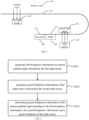
- FIG. 1 shows a schematic diagram of a display device according to an illustrative embodiment of the present disclosure.
- the display device specifically includes a display screen 100, a first light sensor 101, a light source 102, and a second light sensor 103.
- An edge 110 of the display screen 100 in at least one direction is bent toward a back side of the display screen to form a display screen body 112 and a display screen edge part 115.
- the display screen 100 may be encapsulated by a plastic substrate flip chip on pi (COP) process and other encapsulation process.
- COP plastic substrate flip chip on pi
- an edge of a flexible organic light emitting diode (OLED) screen such as an active matrix organic light emitting diode (AMOLED) screen, is bent toward a back side of the screen to form a borderless visual effect, an unbent part of the screen constitutes the display screen body, and a bent part of the screen constitutes the display screen edge part.
- left and right long edges of the display screen may be bent toward the back side of the display screen. It should be understood that other bending modes are also available, which is not specifically limited in the present disclosure.
- the first light sensor 101 is disposed at a back side of the display screen body and is configured to detect a brightness of ambient light of a front side of the display screen body.
- the first light sensor represents an acquiring component provided with a photosensitive element, and is disposed at the back side of the display screen body for acquiring brightness information of ambient light after it passes through the display screen body.
- the display device further includes a flat cable 104 and a driving chip 105, which are disposed at a front side of the display screen edge part, and configured to control the display screen 100 to perform a display operation.
- the driving chip 105 is a display driver integrated circuit (DDIC).
- the light source 102 is disposed at the front side of the display screen edge part and configured to emit light according to a preset brightness.
- the second light sensor 103 is disposed at a back side of the display screen edge part and configured to detect a brightness of the light source.
- the light source 102 and the second light sensor 103 are disposed at a front side and a back side of a bending area of the display screen 100, respectively, and the second light sensor 103 is configured to detect the brightness of the light source. Due to a light transmittance of the display screen 100, the brightness of the light source 102 detected by the second light sensor 103 is different from a true brightness of the light source 102, based on such a difference, a current light transmittance of the display screen can be determined, so that the brightness of the ambient light collected by the first light sensor 101 can be adjusted.
- the display screen edge part is disposed under the display screen body.
- the back side of the display screen body is arranged opposite to a main body of the display screen edge part, so that the light source 102 and the second light sensor 103 are directly arranged opposite to each other, thus improving the accuracy of brightness detection.
- the second light sensor can timely collect the brightness information of the light source, and the light transmittance of the display screen can be determined according to the preset brightness of the light source and be updated timely.
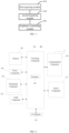
- FIG. 2 shows a schematic flowchart of a detection method for ambient light according to an illustrative embodiment of the present disclosure. The method is applied to a terminal device provided with the above-mentioned display device, and specifically includes steps S201 to S203.
- step S201 first brightness information of current ambient light collected by the first light sensor is acquired.
- the first brightness information of a current ambient where the terminal device is located is collected by the first light sensor in the display device, and the first brightness information represents a brightness value of light received by the first light sensor, i.e., a brightness value of the ambient light after passing through the display screen.
- a preset light transmittance of the display screen is stored in the terminal device, and brightness information of the current ambient light can be determined according to the preset light transmittance and the first brightness information.
- ⁇ ' is the preset light transmittance.
- the preset light transmittance is inconsistent with the current actual light transmittance, resulting in an inaccurate result of the actual brightness information A' of the ambient light.
- the current actual light transmittance may be determined by the following steps.
- step S202 second brightness information of the light source collected by the second light sensor is acquired.
- the second brightness information of the light source is collected by the second light sensor in the display device.
- the second light sensor and the light source are disposed at both sides of the display screen, respectively, the second light sensor can receive light transmitted through the display screen from the light source, and the second brightness information represents a brightness value of the light received by the second light sensor, i.e., a brightness value of the light of the light source after passing through the display screen.
- step S203 target brightness information of the current ambient light is determined according to the first brightness information, the second brightness information and a preset brightness of the light source.
- a reduction degree of the preset brightness by the display screen i.e., the current actual light transmittance of the display screen, can be determined according to the preset brightness and the second brightness information.
- a ratio of the second brightness information to the preset brightness value can be used as the light transmittance of the display screen.
- true brightness information i.e., the target brightness information
- the light transmittance of the terminal device is corrected in time through the second brightness information collected by the second light sensor and the preset brightness of the light source, so that the terminal device can obtain more accurate target brightness information, and the collection accuracy of the terminal device for the ambient light is less affected by screen aging. Further, with the technical solutions according to embodiments of the present disclosure, a light transmittance calibrating step can be omitted in the production process, thereby reducing the production cost.
- the terminal device before acquiring the first brightness information of the current ambient light collected by the first light sensor, can also be controlled to turn on the light source after the display screen is turned off, so that the collection of the second brightness information by the second light sensor will not be affected by the brightness of self-illumination of the display screen due to the operation of the display screen.
- the light source can be automatically turned on in response to a user turning off the display screen of the terminal device, so as to start the solutions described in the present disclosure.
- a brightness of a display image of the display screen can be controlled according to the target brightness information.
- the brightness of the display image of the display screen can be determined according to brightness information of the ambient light and a mapping relationship.
- a mapping relationship table between different brightness information intervals of the ambient light and brightness intervals of the display image of the display screen may be established in advance, or a function curve may be established between the brightness information of the ambient light and the brightness of the display image of the display screen.
- a specific brightness value of the current display image is determined according to the target brightness information of the current ambient light, so that the brightness of the display image of the display screen increases with the increase of the brightness of the ambient light and decreases with the decrease of the brightness of the ambient light, so that a user can watch the display image more conveniently with relieved eye fatigue.
- the present disclosure also provides embodiments of an application function implementation apparatus and a corresponding terminal.
- FIG. 3 A schematic block diagram of a detection apparatus for ambient light according to an illustrative embodiment of the present disclosure is shown in FIG. 3 .
- the apparatus is applied to a terminal device, and the apparatus includes a first acquiring module 301, a second acquiring module 302, and a brightness determining module 303.
- the first acquiring module 301 is configured to acquire first brightness information of current ambient light collected by a first light sensor.
- the second acquiring module 302 is configured to acquire second brightness information of the light source collected by a second light sensor.
- the brightness determining module 303 is configured to determine target brightness information of the current ambient light according to the first brightness information, the second brightness information and a preset brightness of the light source.
- the brightness determining module when determining the target brightness information of the current ambient light according to the first brightness information, the second brightness information and the preset brightness of the light source, is specifically configured to: determine a light transmittance of the display screen according to the second brightness information and the preset brightness of the light source; and determine the target brightness information of the current ambient light according to the first brightness information and the light transmittance of the display screen.
- the apparatus before acquiring the first brightness information of the current ambient light collected by the first light sensor, the apparatus further includes a light source starting module, which is configured to turn on the light source in response to the display screen being turned off.
- the apparatus after determining the target brightness information of the current ambient light, the apparatus further includes a brightness controlling module, which is configured to control a brightness of a display image of the display screen according to the target brightness information.
- the brightness controlling module when controlling the brightness of the display image of the display screen according to the target brightness information, is specifically configured to determine the brightness of the display image of the display screen according to the target brightness information and a mapping relationship, and the mapping relationship represents a correspondence between a brightness of the ambient light and a brightness of the display screen.
- FIG. 4 shows a block diagram of an electronic device according to an illustrative embodiment of the present disclosure.
- the device 400 may be a mobile phone, a computer, a digital broadcast terminal, a messaging device, a game console, a tablet device, a medical device, a fitness device, a personal digital assistant, or the like.
- the device 400 may include one or more of the following components: a processing component 402, a memory 404, a power component 406, a multimedia component 408, an audio component 410, an input/output (I/O) interface 412, a sensor component 414, and a communication component 416.
- the processing component 402 typically controls overall operations of the device 400, such as the operations associated with display, phone calls, data communications, camera operations, and recording operations.
- the processing component 402 can include one or more processors 420 to execute instructions to perform all or some of the steps in the above described methods.
- the processing component 402 may include one or more modules which facilitate the interaction between the processing component 402 and other components.
- the processing component 402 may include a multimedia module to facilitate the interaction between the multimedia component 408 and the processing component 402.
- the memory 404 is configured to store various types of data to support the operation of the device 400. Examples of such data include instructions for any applications or methods operated on the device 400, contact data, phonebook data, messages, pictures, videos, etc.
- the memory 404 may be implemented using any type of volatile or non-volatile memory devices, or a combination thereof, such as a static random access memory (SRAM), an electrically erasable programmable read-only memory (EEPROM), an erasable programmable read-only memory (EPROM), a programmable read-only memory (PROM), a read-only memory (ROM), a magnetic memory, a flash memory, a magnetic or optical disk.
- SRAM static random access memory
- EEPROM electrically erasable programmable read-only memory
- EPROM erasable programmable read-only memory
- PROM programmable read-only memory
- ROM read-only memory
- magnetic memory a magnetic memory
- flash memory a flash memory
- magnetic or optical disk a magnetic or optical
- the power component 406 provides power to various components of the device 400.
- the power component 406 may include a power management system, one or more power sources, and any other components associated with the generation, management, and distribution of power in the device 400.
- the multimedia component 408 includes a screen providing an output interface between the device 400 and the user.
- the screen may include a liquid crystal display (LCD) and a touch panel (TP). If the screen includes the touch panel, the screen may be implemented as a touch screen to receive input signals from the user.
- the touch panel includes one or more touch sensors to sense touches, swipes, and gestures on the touch panel. The touch sensor may not only sense a boundary of a touch or swipe action, but also sense a period of time and a pressure associated with the touch or swipe action.
- the multimedia component 408 includes a front camera and/or a rear camera.
- the front camera and/or the rear camera may receive an external multimedia datum while the device 400 is in an operation mode, such as a photographing mode or a video mode.
- an operation mode such as a photographing mode or a video mode.
- Each of the front camera and the rear camera may be a fixed optical lens system or have focus and optical zoom capability.
- the audio component 410 is configured to output and/or input audio signals.
- the audio component 410 includes a microphone (MIC) configured to receive an external audio signal when the device 400 is in an operation mode, such as a call mode, a recording mode, and a voice recognition mode.
- the received audio signal may be further stored in the memory 404 or transmitted via the communication component 416.
- the audio component 410 further includes a speaker to output audio signals.
- the I/O interface 412 provides an interface between the processing component 402 and peripheral interface modules, such as a keyboard, a click wheel, buttons, and the like.
- the buttons may include, but are not limited to, a home button, a volume button, a starting button, and a locking button.
- the sensor component 414 includes one or more sensors to provide status assessments of various aspects of the device 400. For instance, the sensor component 414 may detect an open/closed status of the device 400, relative positioning of components, e.g., the display and the keypad, of the device 400, a change in position of the device 400 or a component of the device 400, a presence or absence of user contact with the device 400, an orientation or an acceleration/deceleration of the device 400, and a change in temperature of the device 400.
- the sensor component 414 may include a proximity sensor configured to detect the presence of nearby objects without any physical contact.
- the sensor component 414 may include a light sensor, such as a CMOS or CCD image sensor, for use in imaging applications.
- the sensor component 414 may include an accelerometer sensor, a gyroscope sensor, a magnetic sensor, a pressure sensor, or a temperature sensor.
- the communication component 416 is configured to facilitate communication, wired or wireless, between the device 400 and other devices.
- the device 400 can access a wireless network based on a communication standard, such as WiFi, 2G, 3G, 4G, 5G or a combination thereof.
- the communication component 416 receives a broadcast signal or broadcast associated information from an external broadcast management system via a broadcast channel.
- the communication component 416 further includes a near field communication (NFC) module to facilitate short-range communications.
- the NFC module may be implemented based on a radio frequency identification (RFID) technology, an infrared data association (IrDA) technology, an ultra-wideband (UWB) technology, a Bluetooth (BT) technology, and other technologies.
- RFID radio frequency identification
- IrDA infrared data association
- UWB ultra-wideband
- BT Bluetooth
- the device 400 may be implemented with one or more application specific integrated circuits (ASICs), digital signal processors (DSPs), digital signal processing devices (DSPDs), programmable logic devices (PLDs), field programmable gate arrays (FPGAs), controllers, micro-controllers, microprocessors, or other electronic components, for performing the detection method of the above-mentioned electronic devices.
- ASICs application specific integrated circuits
- DSPs digital signal processors
- DSPDs digital signal processing devices
- PLDs programmable logic devices
- FPGAs field programmable gate arrays
- controllers micro-controllers, microprocessors, or other electronic components, for performing the detection method of the above-mentioned electronic devices.
- a non-transitory computer readable storage medium including instructions, such as included in the memory 404, executable by the processor 420 in the device 400, for performing the detection method of the above-mentioned electronic devices.
- the non-transitory computer-readable storage medium may be a ROM, a random access memory (RAM), a CD-ROM, a magnetic tape, a floppy disc, an optical data storage device, and the like.
- a base material of ITO may be glass or a bendable plastic. If the base material is a plastic, a part of the base material connecting a flexible printed circuit (FPC) and a driver integrated circuit (IC) can be bent, so that only a width of a dispensing area needs to be reserved. In this case, the border can be thinner.
- FPC flexible printed circuit
- IC driver integrated circuit
- a "front side" of the display screen, the display screen body or the display screen edge part refers to such a side of the display screen, the display screen body or the display screen edge part that is capable of displaying contents
- a "back side” of the display screen, the display screen body or the display screen edge part refers to a side of the display screen, the display screen body or the display screen edge part that is opposite to the side capable of displaying contents.
- a structure in which a first feature is "on", “at” or “below” a second feature may include an embodiment in which the first feature is in direct contact with the second feature, and may also include an embodiment in which the first feature and the second feature are not in direct contact with each other, but are contacted via an additional feature formed therebetween.
- a first feature "on,” “at,” “above,” or “on top of' a second feature may include an embodiment in which the first feature is right or obliquely “on,” “at,” “above,” or “on top of' the second feature; while a first feature “below,” “under,” or “on bottom of' a second feature may include an embodiment in which the first feature is right or obliquely “below,” “under,” or “on bottom of” the second feature, or just means that the first feature is at a height lower than that of the second feature.
Landscapes
- Engineering & Computer Science (AREA)
- Physics & Mathematics (AREA)
- Computer Hardware Design (AREA)
- General Physics & Mathematics (AREA)
- Theoretical Computer Science (AREA)
- Microelectronics & Electronic Packaging (AREA)
- Controls And Circuits For Display Device (AREA)
Abstract
Description
- At present, with the popularization of intelligent terminal devices, users' pursuit of a display image of the terminal device is continuously improving. At present, the terminal device can detect an intensity of ambient light through a light sensor and adjust a brightness of a display image according to the intensity of ambient light, so that a user can watch the display image with relieved eye fatigue. However, in the existing terminal devices, the light sensor is disposed below the screen, and a light transmittance of the screen changes with the aging of the screen, so ambient brightness information acquired by the light sensor also changes, which is not conducive to the brightness adjustment of the display image.
- The present disclosure relates to the field of optics, and especially to a display device, a detection method and apparatus for ambient light, an electronic device, and a storage medium.
- The present invention is defined by the appended claims. Preferred embodiments are included as dependent claims.
- According to a first aspect of the present disclosure, there is provided a display device. The display device includes: a display screen, an edge of the display screen in at least one direction being bent toward a back side of the display screen to form a display screen body and a display screen edge part; a first light sensor disposed at a back side of the display screen body and configured to detect a brightness of ambient light of a front side of the display screen body; a light source disposed at a front side of the display screen edge part and configured to emit light according to a preset brightness; and a second light sensor disposed at a back side of the display screen edge part and configured to detect a brightness of the light source.
- According to a second aspect of the present disclosure, there is provided a terminal device including the above-mentioned display device.
- According to a third aspect of the present disclosure, there is provided a detection method for ambient light, which is applied to the terminal device and includes: acquiring first brightness information of current ambient light collected by the first light sensor; acquiring second brightness information of the light source collected by the second light sensor; and determining target brightness information of the current ambient light according to the first brightness information, the second brightness information and a preset brightness of the light source.
- It is to be understood that both the foregoing general description and the following detailed description are illustrative and explanatory only and are not restrictive of the present disclosure, as claimed.
- The accompanying drawings, which are incorporated in and constitute a part of this specification, illustrate embodiments consistent with the present disclosure and, together with the description, serve to explain the principles of the present disclosure.
-
FIG. 1 is a schematic diagram showing a display device according to one or more examples of the present disclosure. -
FIG. 2 is a schematic flowchart showing a detection method for ambient light according to one or more examples of the present disclosure. -
FIG. 3 is a schematic block diagram showing a detection apparatus for ambient light according to one or more examples of the present disclosure. -
FIG. 4 is a schematic block diagram showing an electronic device according to one or more examples of the present disclosure. - Reference will now be made in detail to illustrative embodiments, examples of which are illustrated in the accompanying drawings. The following description refers to the accompanying drawings in which the same numbers in different drawings represent the same or similar elements unless otherwise represented. The implementations set forth in the following description of illustrative embodiments do not represent all implementations consistent with the present disclosure. Instead, they are merely examples of apparatuses and methods consistent with aspects related to the present disclosure as recited in the appended claims.
- Terms used in the present disclosure are only for the purpose of describing specific embodiments, but should not be construed to limit the present disclosure. As used in the present disclosure and the appended claims, "a/an", "said" and "the" in singular forms are intended to include plural forms, unless clearly indicated in the context otherwise. It should also be understood that, the term "and/or" used herein represents and cover any one or all possible combinations of one or more associated listed items.
- It should be understood that, although terms such as "first," "second" and "third" may be used in the present disclosure for describing various information, these information should not be limited by these terms. These terms are only used for distinguishing information of the same type from each other. For example, first information may also be referred to as second information, and similarly, second information may also be referred to as first information, without departing from the scope of the present disclosure. As used herein, the term "if" may be construed to mean "when" or "upon" or "in response to determining", depending on the context.
- The terms "module," "sub-module," "circuit," "sub-circuit," "circuitry," "sub-circuitry," "unit," or "sub-unit" may include memory (shared, dedicated, or group) that stores code or instructions that can be executed by one or more processors. A module may include one or more circuits with or without stored code or instructions. The module or circuit may include one or more components that are directly or indirectly connected. These components may or may not be physically attached to, or located adjacent to, one another.
- A unit or module may be implemented purely by software, purely by hardware, or by a combination of hardware and software. In a pure software implementation, for example, the unit or module may include functionally related code blocks or software components that are directly or indirectly linked together, so as to perform a particular function.
- According to a first aspect of the present disclosure, there is provided a display device. The display device includes: a display screen, an edge of the display screen in at least one direction being bent toward a back side of the display screen to form a display screen body and a display screen edge part; a first light sensor disposed at a back side of the display screen body and configured to detect a brightness of ambient light of a front side of the display screen body; a light source disposed at a front side of the display screen edge part and configured to emit light according to a preset brightness; and a second light sensor disposed at a back side of the display screen edge part and configured to detect a brightness of the light source.
- In combination with any embodiment of the present disclosure, the display device further includes a flat cable and a driving chip disposed at the front side of the display screen edge part.
- In combination with any embodiment of the present disclosure, the driving chip is a display driver integrated circuit (DDIC).
- In combination with any embodiment of the present disclosure, the display screen is an organic light emitting diode (OLED) screen encapsulated by a chip on pi (COP) process.
- In combination with any embodiment of the present disclosure, the display screen edge part is disposed under the display screen body.
- In combination with any embodiment of the present disclosure, the back side of the display screen body is arranged opposite to a main body of the display screen edge part.
- According to a second aspect of the present disclosure, there is provided a terminal device including the above-mentioned display device.
- According to a third aspect of the present disclosure, there is provided a detection method for ambient light, which is applied to the terminal device and includes: acquiring first brightness information of current ambient light collected by the first light sensor; acquiring second brightness information of the light source collected by the second light sensor; and determining target brightness information of the current ambient light according to the first brightness information, the second brightness information and a preset brightness of the light source.
- In combination with any embodiment of the present disclosure, determining the target brightness information of the current ambient light according to the first brightness information, the second brightness information and the preset brightness of the light source includes: determining a light transmittance of the display screen according to the second brightness information and the preset brightness of the light source; and determining the target brightness information of the current ambient light according to the first brightness information and the light transmittance of the display screen.
- In combination with any embodiment of the present disclosure, before acquiring the first brightness information of the current ambient light collected by the first light sensor, the method further includes turning on the light source in response to the display screen being turned off.
- In combination with any embodiment of the present disclosure, the method further includes controlling a brightness of a display image of the display screen according to the target brightness information.
- In combination with any embodiment of the present disclosure, controlling the brightness of the display image of the display screen according to the target brightness information includes determining the brightness of the display image of the display screen according to the target brightness information and a mapping relationship, and the mapping relationship represents a correspondence between brightness information of the ambient light and a brightness of the display screen.
- According to a fourth aspect of the present disclosure, there is provided a detection apparatus for ambient light, which is applied to the terminal device, and the apparatus includes: a first acquiring module configured to acquire first brightness information of current ambient light collected by the first light sensor; a second acquiring module configured to acquire second brightness information of the light source collected by the second light sensor; and a brightness determining module configured to determine target brightness information of the current ambient light according to the first brightness information, the second brightness information and a preset brightness of the light source.
- In combination with any embodiment of the present disclosure, the brightness determining module is specifically configured to determine a light transmittance of the display screen according to the second brightness information and the preset brightness of the light source; and determine the target brightness information of the current ambient light according to the first brightness information and the light transmittance of the display screen.
- In combination with any embodiment of the present disclosure, the apparatus further includes a light source starting module, which is configured to turn on the light source in response to the display screen being turned off.
- In combination with any embodiment of the present disclosure, the apparatus further includes a brightness controlling module, which is configured to control a brightness of a display image of the display screen according to the target brightness information.
- In combination with any embodiment of the present disclosure, the brightness controlling module is specifically configured to determine the brightness of the display image of the display screen according to the target brightness information and a mapping relationship, and the mapping relationship represents a correspondence between brightness information of the ambient light and a brightness of the display screen.
- According to a fifth aspect of the present disclosure, there is provided an electronic device, which includes: a processor; and a memory configured to store instructions executable by the processor, and the processor is configured to execute the executable instructions in the memory to implement steps of the method according to any embodiment of the first aspect.
- According to a sixth aspect of the present disclosure, there is provided a computer-readable storage medium having stored therein computer programs that, when executed by a processor, causes the processor to implement steps of the method according to any embodiment of the first aspect.
- The technical solutions provided by embodiments of the present disclosed has the following beneficial effects.
- The light transmittance of the terminal device is corrected in time through the second brightness information collected by the second light sensor and the preset brightness of the light source, so that the terminal device can obtain more accurate target brightness information, and the collection accuracy of the terminal device for ambient light is less affected by screen aging. With the technical solutions according to embodiments of the present disclosure, a light transmittance calibrating step can be omitted in the production process, thereby reducing the production cost.
-
FIG. 1 shows a schematic diagram of a display device according to an illustrative embodiment of the present disclosure. - As shown in
FIG. 1 , the display device specifically includes adisplay screen 100, afirst light sensor 101, alight source 102, and asecond light sensor 103. - An
edge 110 of thedisplay screen 100 in at least one direction is bent toward a back side of the display screen to form adisplay screen body 112 and a displayscreen edge part 115. - Optionally, the
display screen 100 may be encapsulated by a plastic substrate flip chip on pi (COP) process and other encapsulation process. For example, an edge of a flexible organic light emitting diode (OLED) screen, such as an active matrix organic light emitting diode (AMOLED) screen, is bent toward a back side of the screen to form a borderless visual effect, an unbent part of the screen constitutes the display screen body, and a bent part of the screen constitutes the display screen edge part. In an example, left and right long edges of the display screen may be bent toward the back side of the display screen. It should be understood that other bending modes are also available, which is not specifically limited in the present disclosure. - The
first light sensor 101 is disposed at a back side of the display screen body and is configured to detect a brightness of ambient light of a front side of the display screen body. - Optionally, the first light sensor represents an acquiring component provided with a photosensitive element, and is disposed at the back side of the display screen body for acquiring brightness information of ambient light after it passes through the display screen body. In an example, the display device further includes a
flat cable 104 and adriving chip 105, which are disposed at a front side of the display screen edge part, and configured to control thedisplay screen 100 to perform a display operation. In an example, thedriving chip 105 is a display driver integrated circuit (DDIC). - The
light source 102 is disposed at the front side of the display screen edge part and configured to emit light according to a preset brightness. - The second
light sensor 103 is disposed at a back side of the display screen edge part and configured to detect a brightness of the light source. - Optionally, the
light source 102 and the secondlight sensor 103 are disposed at a front side and a back side of a bending area of thedisplay screen 100, respectively, and the secondlight sensor 103 is configured to detect the brightness of the light source. Due to a light transmittance of thedisplay screen 100, the brightness of thelight source 102 detected by the secondlight sensor 103 is different from a true brightness of thelight source 102, based on such a difference, a current light transmittance of the display screen can be determined, so that the brightness of the ambient light collected by thefirst light sensor 101 can be adjusted. In an example, the display screen edge part is disposed under the display screen body. In an example, the back side of the display screen body is arranged opposite to a main body of the display screen edge part, so that thelight source 102 and the secondlight sensor 103 are directly arranged opposite to each other, thus improving the accuracy of brightness detection. - Based on a structure of the display device provided by the present disclosure, the second light sensor can timely collect the brightness information of the light source, and the light transmittance of the display screen can be determined according to the preset brightness of the light source and be updated timely.
-
FIG. 2 shows a schematic flowchart of a detection method for ambient light according to an illustrative embodiment of the present disclosure. The method is applied to a terminal device provided with the above-mentioned display device, and specifically includes steps S201 to S203. - In the step S201, first brightness information of current ambient light collected by the first light sensor is acquired.
- Optionally, the first brightness information of a current ambient where the terminal device is located is collected by the first light sensor in the display device, and the first brightness information represents a brightness value of light received by the first light sensor, i.e., a brightness value of the ambient light after passing through the display screen.
- Generally, a preset light transmittance of the display screen is stored in the terminal device, and brightness information of the current ambient light can be determined according to the preset light transmittance and the first brightness information. In an example, actual brightness information of the current ambient light can be determined by formula (1):

- In step S202, second brightness information of the light source collected by the second light sensor is acquired.
- Optionally, the second brightness information of the light source is collected by the second light sensor in the display device. As the second light sensor and the light source are disposed at both sides of the display screen, respectively, the second light sensor can receive light transmitted through the display screen from the light source, and the second brightness information represents a brightness value of the light received by the second light sensor, i.e., a brightness value of the light of the light source after passing through the display screen.
- In step S203, target brightness information of the current ambient light is determined according to the first brightness information, the second brightness information and a preset brightness of the light source.
- Firstly, since the preset brightness of the light source is a known quantity, a reduction degree of the preset brightness by the display screen, i.e., the current actual light transmittance of the display screen, can be determined according to the preset brightness and the second brightness information. In an example, a ratio of the second brightness information to the preset brightness value can be used as the light transmittance of the display screen.
- After that, true brightness information, i.e., the target brightness information, of the current ambient can be determined based on the light transmittance and the first brightness information. In an example, the target brightness information can be determined by formula (2):

- According to the method of the present disclosure, the light transmittance of the terminal device is corrected in time through the second brightness information collected by the second light sensor and the preset brightness of the light source, so that the terminal device can obtain more accurate target brightness information, and the collection accuracy of the terminal device for the ambient light is less affected by screen aging. Further, with the technical solutions according to embodiments of the present disclosure, a light transmittance calibrating step can be omitted in the production process, thereby reducing the production cost.
- In an optional embodiment, before acquiring the first brightness information of the current ambient light collected by the first light sensor, the terminal device can also be controlled to turn on the light source after the display screen is turned off, so that the collection of the second brightness information by the second light sensor will not be affected by the brightness of self-illumination of the display screen due to the operation of the display screen. In an example, the light source can be automatically turned on in response to a user turning off the display screen of the terminal device, so as to start the solutions described in the present disclosure.
- In another optional embodiment, after determining the target brightness information of the current ambient light, a brightness of a display image of the display screen can be controlled according to the target brightness information.
- Specifically, the brightness of the display image of the display screen can be determined according to brightness information of the ambient light and a mapping relationship. For example, a corresponding mapping relationship table between different brightness information intervals of the ambient light and brightness intervals of the display image of the display screen may be established in advance, or a function curve may be established between the brightness information of the ambient light and the brightness of the display image of the display screen. A specific brightness value of the current display image is determined according to the target brightness information of the current ambient light, so that the brightness of the display image of the display screen increases with the increase of the brightness of the ambient light and decreases with the decrease of the brightness of the ambient light, so that a user can watch the display image more conveniently with relieved eye fatigue.
- For the sake of brief description, the foregoing method embodiments are expressed as combinations of a series of actions, but those skilled in the art should be understood that the present disclosure is not limited by the described action sequence, as some steps can be performed in other sequences or simultaneously according to the present disclosure.
- Also, those skilled in the art should be understood that the embodiments described in the specification are optional embodiments, and actions and modules involved therein are not necessarily required for the present disclosure.
- Corresponding to the foregoing embodiments of the application function implementation method, the present disclosure also provides embodiments of an application function implementation apparatus and a corresponding terminal.
- A schematic block diagram of a detection apparatus for ambient light according to an illustrative embodiment of the present disclosure is shown in
FIG. 3 . The apparatus is applied to a terminal device, and the apparatus includes a first acquiringmodule 301, a second acquiringmodule 302, and abrightness determining module 303. - The first acquiring
module 301 is configured to acquire first brightness information of current ambient light collected by a first light sensor. - The second acquiring
module 302 is configured to acquire second brightness information of the light source collected by a second light sensor. - The
brightness determining module 303 is configured to determine target brightness information of the current ambient light according to the first brightness information, the second brightness information and a preset brightness of the light source. - In combination with any embodiment of the present disclosure, when determining the target brightness information of the current ambient light according to the first brightness information, the second brightness information and the preset brightness of the light source, the brightness determining module is specifically configured to: determine a light transmittance of the display screen according to the second brightness information and the preset brightness of the light source; and determine the target brightness information of the current ambient light according to the first brightness information and the light transmittance of the display screen.
- In combination with any embodiment of the present disclosure, before acquiring the first brightness information of the current ambient light collected by the first light sensor, the apparatus further includes a light source starting module, which is configured to turn on the light source in response to the display screen being turned off.
- In combination with any embodiment of the present disclosure, after determining the target brightness information of the current ambient light, the apparatus further includes a brightness controlling module, which is configured to control a brightness of a display image of the display screen according to the target brightness information.
- In combination with any embodiment of the present disclosure, when controlling the brightness of the display image of the display screen according to the target brightness information, the brightness controlling module is specifically configured to determine the brightness of the display image of the display screen according to the target brightness information and a mapping relationship, and the mapping relationship represents a correspondence between a brightness of the ambient light and a brightness of the display screen.
- With respect to the apparatus embodiments, since they basically correspond to the method embodiments, relevant parts can refer to the description of the embodiments of the method. The above-described apparatus embodiments are only illustrative, in which the units described above as separate components may be or may not be physically separated, and components shown as units may be or may not be physical units, that is, they may be located in one place or distributed over a plurality of network units. Some or all of the modules can be selected according to the actual needs to realize the purpose of the present disclosure. These can be understood and implemented by those skilled in the art without creative labor.
-
FIG. 4 shows a block diagram of an electronic device according to an illustrative embodiment of the present disclosure. - Reference is made to
FIG. 4 , which illustratively shows a block diagram of an electronic device. For example, thedevice 400 may be a mobile phone, a computer, a digital broadcast terminal, a messaging device, a game console, a tablet device, a medical device, a fitness device, a personal digital assistant, or the like. - Referring to
FIG. 4 , thedevice 400 may include one or more of the following components: aprocessing component 402, amemory 404, apower component 406, a multimedia component 408, anaudio component 410, an input/output (I/O)interface 412, asensor component 414, and acommunication component 416. - The
processing component 402 typically controls overall operations of thedevice 400, such as the operations associated with display, phone calls, data communications, camera operations, and recording operations. Theprocessing component 402 can include one ormore processors 420 to execute instructions to perform all or some of the steps in the above described methods. Moreover, theprocessing component 402 may include one or more modules which facilitate the interaction between theprocessing component 402 and other components. For instance, theprocessing component 402 may include a multimedia module to facilitate the interaction between the multimedia component 408 and theprocessing component 402. - The
memory 404 is configured to store various types of data to support the operation of thedevice 400. Examples of such data include instructions for any applications or methods operated on thedevice 400, contact data, phonebook data, messages, pictures, videos, etc. Thememory 404 may be implemented using any type of volatile or non-volatile memory devices, or a combination thereof, such as a static random access memory (SRAM), an electrically erasable programmable read-only memory (EEPROM), an erasable programmable read-only memory (EPROM), a programmable read-only memory (PROM), a read-only memory (ROM), a magnetic memory, a flash memory, a magnetic or optical disk. - The
power component 406 provides power to various components of thedevice 400. Thepower component 406 may include a power management system, one or more power sources, and any other components associated with the generation, management, and distribution of power in thedevice 400. - The multimedia component 408 includes a screen providing an output interface between the
device 400 and the user. In some embodiments, the screen may include a liquid crystal display (LCD) and a touch panel (TP). If the screen includes the touch panel, the screen may be implemented as a touch screen to receive input signals from the user. The touch panel includes one or more touch sensors to sense touches, swipes, and gestures on the touch panel. The touch sensor may not only sense a boundary of a touch or swipe action, but also sense a period of time and a pressure associated with the touch or swipe action. In some embodiments, the multimedia component 408 includes a front camera and/or a rear camera. The front camera and/or the rear camera may receive an external multimedia datum while thedevice 400 is in an operation mode, such as a photographing mode or a video mode. Each of the front camera and the rear camera may be a fixed optical lens system or have focus and optical zoom capability. - The
audio component 410 is configured to output and/or input audio signals. For example, theaudio component 410 includes a microphone (MIC) configured to receive an external audio signal when thedevice 400 is in an operation mode, such as a call mode, a recording mode, and a voice recognition mode. The received audio signal may be further stored in thememory 404 or transmitted via thecommunication component 416. In some embodiments, theaudio component 410 further includes a speaker to output audio signals. - The I/
O interface 412 provides an interface between theprocessing component 402 and peripheral interface modules, such as a keyboard, a click wheel, buttons, and the like. The buttons may include, but are not limited to, a home button, a volume button, a starting button, and a locking button. - The
sensor component 414 includes one or more sensors to provide status assessments of various aspects of thedevice 400. For instance, thesensor component 414 may detect an open/closed status of thedevice 400, relative positioning of components, e.g., the display and the keypad, of thedevice 400, a change in position of thedevice 400 or a component of thedevice 400, a presence or absence of user contact with thedevice 400, an orientation or an acceleration/deceleration of thedevice 400, and a change in temperature of thedevice 400. Thesensor component 414 may include a proximity sensor configured to detect the presence of nearby objects without any physical contact. Thesensor component 414 may include a light sensor, such as a CMOS or CCD image sensor, for use in imaging applications. In some embodiments, thesensor component 414 may include an accelerometer sensor, a gyroscope sensor, a magnetic sensor, a pressure sensor, or a temperature sensor. - The
communication component 416 is configured to facilitate communication, wired or wireless, between thedevice 400 and other devices. Thedevice 400 can access a wireless network based on a communication standard, such as WiFi, 2G, 3G, 4G, 5G or a combination thereof. In an illustrative embodiment, thecommunication component 416 receives a broadcast signal or broadcast associated information from an external broadcast management system via a broadcast channel. In an illustrative embodiment, thecommunication component 416 further includes a near field communication (NFC) module to facilitate short-range communications. For example, the NFC module may be implemented based on a radio frequency identification (RFID) technology, an infrared data association (IrDA) technology, an ultra-wideband (UWB) technology, a Bluetooth (BT) technology, and other technologies. - In an illustrative embodiment, the
device 400 may be implemented with one or more application specific integrated circuits (ASICs), digital signal processors (DSPs), digital signal processing devices (DSPDs), programmable logic devices (PLDs), field programmable gate arrays (FPGAs), controllers, micro-controllers, microprocessors, or other electronic components, for performing the detection method of the above-mentioned electronic devices. - In an illustrative embodiment, there is provided a non-transitory computer readable storage medium including instructions, such as included in the
memory 404, executable by theprocessor 420 in thedevice 400, for performing the detection method of the above-mentioned electronic devices. For example, the non-transitory computer-readable storage medium may be a ROM, a random access memory (RAM), a CD-ROM, a magnetic tape, a floppy disc, an optical data storage device, and the like. - Other embodiments of the present disclosure will be apparent to those skilled in the art from consideration of the specification and practice of the present disclosure described here. The present disclosure is intended to cover any variations, uses, or adaptations of the present disclosure following the general principles thereof and including such departures from the present disclosure as come within known or customary practice in the art. It is intended that the specification and examples be considered as exemplary only, with a true scope of the present disclosure being indicated by the following claims.
- It will be appreciated that the present disclosure is not limited to the exact construction that has been described above and illustrated in the accompanying drawings, and that various modifications and changes can be made without departing from the scope of the invention as defined by the appended claims.
- In embodiments of the present disclosure, for COP encapsulation process, only the OLED screen can be used, because in the OLED screen, a base material of ITO may be glass or a bendable plastic. If the base material is a plastic, a part of the base material connecting a flexible printed circuit (FPC) and a driver integrated circuit (IC) can be bent, so that only a width of a dispensing area needs to be reserved. In this case, the border can be thinner.
- It should be understood that the term a "front side" of the display screen, the display screen body or the display screen edge part refers to such a side of the display screen, the display screen body or the display screen edge part that is capable of displaying contents, and a "back side" of the display screen, the display screen body or the display screen edge part refers to a side of the display screen, the display screen body or the display screen edge part that is opposite to the side capable of displaying contents.
- In the present invention, unless specified or limited otherwise, a structure in which a first feature is "on", "at" or "below" a second feature may include an embodiment in which the first feature is in direct contact with the second feature, and may also include an embodiment in which the first feature and the second feature are not in direct contact with each other, but are contacted via an additional feature formed therebetween. Furthermore, a first feature "on," "at," "above," or "on top of' a second feature may include an embodiment in which the first feature is right or obliquely "on," "at," "above," or "on top of' the second feature; while a first feature "below," "under," or "on bottom of' a second feature may include an embodiment in which the first feature is right or obliquely "below," "under," or "on bottom of" the second feature, or just means that the first feature is at a height lower than that of the second feature.
Claims (15)
- A display device, comprising:a display screen (100) comprising a display screen body (112) and a display screen edge part (115), at least one edge of the display screen (100) being bent toward a back side of the display screen (100) to form the display screen body (112) and the display screen edge part (115);a first light sensor (101) disposed at a back side of the display screen body (112) and configured to detect a brightness of ambient light of a front side of the display screen body (112);a light source (102) disposed at a front side of the display screen edge part (115) and configured to emit light according to a preset brightness; anda second light sensor (103) disposed at a back side of the display screen edge part (115) and configured to detect a brightness of the light source (102).
- The display device of claim 1, further comprising a flat cable (104) and a driving chip (105) disposed at the front side of the display screen edge part (115).
- The display device of claim 2, wherein the driving chip (105) is a display driver integrated circuit.
- The display device of any one of claims 1 to 3, wherein the display screen (100) is an organic light emitting diode (OLED) screen encapsulated by a chip on pi (COP) process.
- The display device of any one of claims 1 to 4, wherein the display screen edge part is disposed under the display screen body (112).
- A terminal device, comprising the display device according to any one of claims 1 to 5.
- A method for detecting ambient light, applied to the terminal device of claim 6, comprising:acquiring (S201) first brightness information of current ambient light collected by the first light sensor (101);acquiring (S202) second brightness information of the light source (102) collected by the second light sensor (103); anddetermining (S203) target brightness information of the current ambient light according to the first brightness information, the second brightness information and a preset brightness of the light source (102).
- The method of claim 7, wherein determining (S203) the target brightness information of the current ambient light according to the first brightness information, the second brightness information and the preset brightness of the light source (102) comprises:determining a light transmittance of the display screen (100) according to the second brightness information and the preset brightness of the light source (102); anddetermining the target brightness information of the current ambient light according to the first brightness information and the light transmittance of the display screen (100).
- The method of claim 7 or 8, before acquiring (S201 the first brightness information of the current ambient light collected by the first light sensor (101), further comprising:
turning on the light source (102) in response to the display screen (100) being turned off. - The method of any one of claims 7 to 9, further comprising:
controlling a brightness of a display image of the display screen (100) according to the target brightness information. - The method of claim 10, wherein controlling the brightness of the display image of the display screen (100) according to the target brightness information comprises:
determining the brightness of the display image of the display screen (100) according to the target brightness information and a mapping relationship, wherein the mapping relationship represents a correspondence between brightness information of the ambient light and a brightness of the display screen (100). - A detection apparatus for ambient light, applied to the terminal device of claim 6, comprising:a first acquiring module (301) configured to acquire first brightness information of current ambient light collected by the first light sensor;a second acquiring module (302) configured to acquire second brightness information of the light source collected by the second light sensor; anda brightness determining module (303) configured to determine target brightness information of the current ambient light according to the first brightness information, the second brightness information and a preset brightness of the light source.
- The detection apparatus of claim 12, wherein the brightness determining module (303) is configured to:determine a light transmittance of the display screen according to the second brightness information and the preset brightness of the light source; anddetermine the target brightness information of the current ambient light according to the first brightness information and the light transmittance of the display screen.
- An electronic device, comprising:a processor (420); anda memory (404) configured to store instructions executable by the processor,wherein the processor is configured to execute the executable instructions in the memory to implement steps of the method according to any one of claims 7 to 11.
- A computer-readable storage medium having stored therein computer programs that, when executed by a processor, causes the processor to implement steps of the method according to any one of claims 7 to 11.
Applications Claiming Priority (1)
| Application Number | Priority Date | Filing Date | Title |
|---|---|---|---|
| CN202211146414.6A CN117789675A (en) | 2022-09-20 | 2022-09-20 | Display modules, ambient light detection methods, devices, electronic equipment and storage media |
Publications (2)
| Publication Number | Publication Date |
|---|---|
| EP4343749A1 true EP4343749A1 (en) | 2024-03-27 |
| EP4343749B1 EP4343749B1 (en) | 2025-10-29 |
Family
ID=84688152
Family Applications (1)
| Application Number | Title | Priority Date | Filing Date |
|---|---|---|---|
| EP22216964.1A Active EP4343749B1 (en) | 2022-09-20 | 2022-12-28 | Display device, detection method for ambient light, electronic device and storage medium |
Country Status (3)
| Country | Link |
|---|---|
| US (1) | US11749153B1 (en) |
| EP (1) | EP4343749B1 (en) |
| CN (1) | CN117789675A (en) |
Citations (3)
| Publication number | Priority date | Publication date | Assignee | Title |
|---|---|---|---|---|
| CN108848265A (en) * | 2018-06-21 | 2018-11-20 | 广东小天才科技有限公司 | Screen brightness adjusting method and device for local area, terminal and storage medium |
| CN112905135A (en) * | 2021-03-08 | 2021-06-04 | 北京小米移动软件有限公司 | Screen brightness processing method, electronic device and storage medium |
| US20210225982A1 (en) * | 2018-09-12 | 2021-07-22 | Wuhan China Star Optoelectronics Semiconductor Display Technology Co., Ltd. | Flexible display panel |
Family Cites Families (9)
| Publication number | Priority date | Publication date | Assignee | Title |
|---|---|---|---|---|
| US20180204524A1 (en) * | 2017-01-19 | 2018-07-19 | Microsoft Technology Licensing, Llc | Controlling brightness of an emissive display |
| US10403189B2 (en) * | 2017-12-19 | 2019-09-03 | Dell Products L.P. | Compensating for temperature induced differences in a computing device having dual-displays or a foldable display |
| KR102888833B1 (en) * | 2019-09-24 | 2025-11-21 | 삼성전자주식회사 | Foldable electronic device for processing sensor data based on angle change and operating method thereof |
| CN113535006A (en) * | 2020-04-13 | 2021-10-22 | 群创光电股份有限公司 | Operation method and electronic device of electronic device for detecting optical signal |
| CN111854646B (en) * | 2020-06-30 | 2022-02-22 | 维沃移动通信有限公司 | Electronic device |
| CN112130736A (en) * | 2020-09-29 | 2020-12-25 | 联想(北京)有限公司 | Control method, electronic device and computer readable storage medium |
| EP4210306B1 (en) * | 2021-01-14 | 2025-06-04 | Samsung Electronics Co., Ltd. | Electronic device and brightness adjustment method |
| US11594199B2 (en) * | 2021-04-30 | 2023-02-28 | Apple Inc. | Electronic device with multiple ambient light sensors |
| EP4383043A4 (en) * | 2021-11-05 | 2024-12-25 | Samsung Electronics Co., Ltd. | IMAGE PROVIDING METHOD AND ELECTRONIC DEVICE SUPPORTING SAME |
-
2022
- 2022-09-20 CN CN202211146414.6A patent/CN117789675A/en active Pending
- 2022-12-27 US US18/089,552 patent/US11749153B1/en active Active
- 2022-12-28 EP EP22216964.1A patent/EP4343749B1/en active Active
Patent Citations (3)
| Publication number | Priority date | Publication date | Assignee | Title |
|---|---|---|---|---|
| CN108848265A (en) * | 2018-06-21 | 2018-11-20 | 广东小天才科技有限公司 | Screen brightness adjusting method and device for local area, terminal and storage medium |
| US20210225982A1 (en) * | 2018-09-12 | 2021-07-22 | Wuhan China Star Optoelectronics Semiconductor Display Technology Co., Ltd. | Flexible display panel |
| CN112905135A (en) * | 2021-03-08 | 2021-06-04 | 北京小米移动软件有限公司 | Screen brightness processing method, electronic device and storage medium |
Also Published As
| Publication number | Publication date |
|---|---|
| US11749153B1 (en) | 2023-09-05 |
| EP4343749B1 (en) | 2025-10-29 |
| CN117789675A (en) | 2024-03-29 |
Similar Documents
| Publication | Publication Date | Title |
|---|---|---|
| US11015973B2 (en) | Method and apparatus for acquiring ambient light brightness based on the luminance value of the screen of a terminal device | |
| AU2018370704B2 (en) | Method for detecting ambient light intensity, storage medium and electronic device | |
| RU2645302C1 (en) | Method and apparatus for setting screen brightness | |
| CN107145856B (en) | Organic light-emitting diode display module and control method thereof | |
| US20200043427A1 (en) | Backlight adjusting method and backlight adjusting device | |
| EP3131087B1 (en) | Method and device for reducing display brightness | |
| CN108806627B (en) | Ambient light brightness determination method, device and storage medium | |
| EP3130985B1 (en) | Method and device for detecting pressure in mobile terminal | |
| US10444953B2 (en) | View angle switching method and apparatus | |
| US20190312093A1 (en) | Display panel and photoelectric detection method | |
| CN112714205A (en) | Method and device for determining ambient illumination intensity and storage medium | |
| EP3232301B1 (en) | Mobile terminal and virtual key processing method | |
| US10234924B2 (en) | Method and apparatus for displaying time on mobile device | |
| CN112016541B (en) | Electronic device and fingerprint recognition image acquisition method | |
| CN112781832A (en) | Method, apparatus, device and medium for determining ambient light for terminal device | |
| US11221734B2 (en) | Punch-hole screen display method and apparatus | |
| CN111243506B (en) | Screen brightness adjustment method, device, device and storage medium | |
| CN111754929B (en) | Ambient light parameter collection method, device and storage medium | |
| EP3629318B1 (en) | Method and apparatus for compensating operating parameter of display circuit | |
| EP3182256A1 (en) | Touch control button, touch control panel and touch control terminal | |
| US20210120276A1 (en) | Screen display device, method and device for controlling screen display and storage medium | |
| EP4343749B1 (en) | Display device, detection method for ambient light, electronic device and storage medium | |
| CN112905135B (en) | Screen brightness processing method, electronic device and storage medium | |
| CN113808549A (en) | Brightness adjusting method and device for LCD display screen, electronic equipment and medium | |
| CN111383568B (en) | Display control methods and devices, electronic devices and computer-readable storage media |
Legal Events
| Date | Code | Title | Description |
|---|---|---|---|
| PUAI | Public reference made under article 153(3) epc to a published international application that has entered the european phase |
Free format text: ORIGINAL CODE: 0009012 |
|
| STAA | Information on the status of an ep patent application or granted ep patent |
Free format text: STATUS: REQUEST FOR EXAMINATION WAS MADE |
|
| 17P | Request for examination filed |
Effective date: 20230118 |
|
| AK | Designated contracting states |
Kind code of ref document: A1 Designated state(s): AL AT BE BG CH CY CZ DE DK EE ES FI FR GB GR HR HU IE IS IT LI LT LU LV MC ME MK MT NL NO PL PT RO RS SE SI SK SM TR |
|
| GRAP | Despatch of communication of intention to grant a patent |
Free format text: ORIGINAL CODE: EPIDOSNIGR1 |
|
| STAA | Information on the status of an ep patent application or granted ep patent |
Free format text: STATUS: GRANT OF PATENT IS INTENDED |
|
| INTG | Intention to grant announced |
Effective date: 20250605 |
|
| GRAS | Grant fee paid |
Free format text: ORIGINAL CODE: EPIDOSNIGR3 |
|
| P01 | Opt-out of the competence of the unified patent court (upc) registered |
Free format text: CASE NUMBER: UPC_APP_2736_4343749/2025 Effective date: 20250807 |
|
| GRAA | (expected) grant |
Free format text: ORIGINAL CODE: 0009210 |
|
| STAA | Information on the status of an ep patent application or granted ep patent |
Free format text: STATUS: THE PATENT HAS BEEN GRANTED |
|
| AK | Designated contracting states |
Kind code of ref document: B1 Designated state(s): AL AT BE BG CH CY CZ DE DK EE ES FI FR GB GR HR HU IE IS IT LI LT LU LV MC ME MK MT NL NO PL PT RO RS SE SI SK SM TR |
|
| REG | Reference to a national code |
Ref country code: CH Ref legal event code: F10 Free format text: ST27 STATUS EVENT CODE: U-0-0-F10-F00 (AS PROVIDED BY THE NATIONAL OFFICE) Effective date: 20251029 Ref country code: GB Ref legal event code: FG4D |
|
| REG | Reference to a national code |
Ref country code: IE Ref legal event code: FG4D |
|
| REG | Reference to a national code |
Ref country code: DE Ref legal event code: R096 Ref document number: 602022023888 Country of ref document: DE |
|
| PGFP | Annual fee paid to national office [announced via postgrant information from national office to epo] |
Ref country code: DE Payment date: 20251126 Year of fee payment: 4 |
|
| PGFP | Annual fee paid to national office [announced via postgrant information from national office to epo] |
Ref country code: AT Payment date: 20260113 Year of fee payment: 4 |
|
| REG | Reference to a national code |
Ref country code: NL Ref legal event code: MP Effective date: 20251029 |
|
| PG25 | Lapsed in a contracting state [announced via postgrant information from national office to epo] |
Ref country code: ES Free format text: LAPSE BECAUSE OF FAILURE TO SUBMIT A TRANSLATION OF THE DESCRIPTION OR TO PAY THE FEE WITHIN THE PRESCRIBED TIME-LIMIT Effective date: 20251029 |
|
| REG | Reference to a national code |
Ref country code: LT Ref legal event code: MG9D |
|
| PG25 | Lapsed in a contracting state [announced via postgrant information from national office to epo] |
Ref country code: NO Free format text: LAPSE BECAUSE OF FAILURE TO SUBMIT A TRANSLATION OF THE DESCRIPTION OR TO PAY THE FEE WITHIN THE PRESCRIBED TIME-LIMIT Effective date: 20260129 |
|
| PG25 | Lapsed in a contracting state [announced via postgrant information from national office to epo] |
Ref country code: HR Free format text: LAPSE BECAUSE OF FAILURE TO SUBMIT A TRANSLATION OF THE DESCRIPTION OR TO PAY THE FEE WITHIN THE PRESCRIBED TIME-LIMIT Effective date: 20251029 Ref country code: AT Free format text: LAPSE BECAUSE OF FAILURE TO SUBMIT A TRANSLATION OF THE DESCRIPTION OR TO PAY THE FEE WITHIN THE PRESCRIBED TIME-LIMIT Effective date: 20251029 Ref country code: FI Free format text: LAPSE BECAUSE OF FAILURE TO SUBMIT A TRANSLATION OF THE DESCRIPTION OR TO PAY THE FEE WITHIN THE PRESCRIBED TIME-LIMIT Effective date: 20251029 |
|
| REG | Reference to a national code |
Ref country code: AT Ref legal event code: MK05 Ref document number: 1852587 Country of ref document: AT Kind code of ref document: T Effective date: 20251029 |
|
| PG25 | Lapsed in a contracting state [announced via postgrant information from national office to epo] |
Ref country code: NL Free format text: LAPSE BECAUSE OF FAILURE TO SUBMIT A TRANSLATION OF THE DESCRIPTION OR TO PAY THE FEE WITHIN THE PRESCRIBED TIME-LIMIT Effective date: 20251029 |
|
| PG25 | Lapsed in a contracting state [announced via postgrant information from national office to epo] |
Ref country code: RS Free format text: LAPSE BECAUSE OF FAILURE TO SUBMIT A TRANSLATION OF THE DESCRIPTION OR TO PAY THE FEE WITHIN THE PRESCRIBED TIME-LIMIT Effective date: 20260129 |
|
| PG25 | Lapsed in a contracting state [announced via postgrant information from national office to epo] |
Ref country code: IS Free format text: LAPSE BECAUSE OF FAILURE TO SUBMIT A TRANSLATION OF THE DESCRIPTION OR TO PAY THE FEE WITHIN THE PRESCRIBED TIME-LIMIT Effective date: 20260228 |
|
| PG25 | Lapsed in a contracting state [announced via postgrant information from national office to epo] |
Ref country code: PT Free format text: LAPSE BECAUSE OF FAILURE TO SUBMIT A TRANSLATION OF THE DESCRIPTION OR TO PAY THE FEE WITHIN THE PRESCRIBED TIME-LIMIT Effective date: 20260302 |
|
| PG25 | Lapsed in a contracting state [announced via postgrant information from national office to epo] |
Ref country code: PL Free format text: LAPSE BECAUSE OF FAILURE TO SUBMIT A TRANSLATION OF THE DESCRIPTION OR TO PAY THE FEE WITHIN THE PRESCRIBED TIME-LIMIT Effective date: 20251029 |
|
| PG25 | Lapsed in a contracting state [announced via postgrant information from national office to epo] |
Ref country code: LV Free format text: LAPSE BECAUSE OF FAILURE TO SUBMIT A TRANSLATION OF THE DESCRIPTION OR TO PAY THE FEE WITHIN THE PRESCRIBED TIME-LIMIT Effective date: 20251029 |
|
| PG25 | Lapsed in a contracting state [announced via postgrant information from national office to epo] |
Ref country code: BG Free format text: LAPSE BECAUSE OF FAILURE TO SUBMIT A TRANSLATION OF THE DESCRIPTION OR TO PAY THE FEE WITHIN THE PRESCRIBED TIME-LIMIT Effective date: 20251029 |