EP4343368A1 - Radar-based segmented presence detection - Google Patents
Radar-based segmented presence detection Download PDFInfo
- Publication number
- EP4343368A1 EP4343368A1 EP23198586.2A EP23198586A EP4343368A1 EP 4343368 A1 EP4343368 A1 EP 4343368A1 EP 23198586 A EP23198586 A EP 23198586A EP 4343368 A1 EP4343368 A1 EP 4343368A1
- Authority
- EP
- European Patent Office
- Prior art keywords
- range
- slow
- time data
- zone
- generating
- Prior art date
- Legal status (The legal status is an assumption and is not a legal conclusion. Google has not performed a legal analysis and makes no representation as to the accuracy of the status listed.)
- Pending
Links
Images


Classifications
-
- G—PHYSICS
- G01—MEASURING; TESTING
- G01S—RADIO DIRECTION-FINDING; RADIO NAVIGATION; DETERMINING DISTANCE OR VELOCITY BY USE OF RADIO WAVES; LOCATING OR PRESENCE-DETECTING BY USE OF THE REFLECTION OR RERADIATION OF RADIO WAVES; ANALOGOUS ARRANGEMENTS USING OTHER WAVES
- G01S13/00—Systems using the reflection or reradiation of radio waves, e.g. radar systems; Analogous systems using reflection or reradiation of waves whose nature or wavelength is irrelevant or unspecified
- G01S13/02—Systems using reflection of radio waves, e.g. primary radar systems; Analogous systems
- G01S13/04—Systems determining presence of a target
-
- G—PHYSICS
- G01—MEASURING; TESTING
- G01S—RADIO DIRECTION-FINDING; RADIO NAVIGATION; DETERMINING DISTANCE OR VELOCITY BY USE OF RADIO WAVES; LOCATING OR PRESENCE-DETECTING BY USE OF THE REFLECTION OR RERADIATION OF RADIO WAVES; ANALOGOUS ARRANGEMENTS USING OTHER WAVES
- G01S13/00—Systems using the reflection or reradiation of radio waves, e.g. radar systems; Analogous systems using reflection or reradiation of waves whose nature or wavelength is irrelevant or unspecified
- G01S13/02—Systems using reflection of radio waves, e.g. primary radar systems; Analogous systems
- G01S13/06—Systems determining position data of a target
- G01S13/42—Simultaneous measurement of distance and other co-ordinates
-
- G—PHYSICS
- G01—MEASURING; TESTING
- G01S—RADIO DIRECTION-FINDING; RADIO NAVIGATION; DETERMINING DISTANCE OR VELOCITY BY USE OF RADIO WAVES; LOCATING OR PRESENCE-DETECTING BY USE OF THE REFLECTION OR RERADIATION OF RADIO WAVES; ANALOGOUS ARRANGEMENTS USING OTHER WAVES
- G01S13/00—Systems using the reflection or reradiation of radio waves, e.g. radar systems; Analogous systems using reflection or reradiation of waves whose nature or wavelength is irrelevant or unspecified
- G01S13/02—Systems using reflection of radio waves, e.g. primary radar systems; Analogous systems
- G01S13/06—Systems determining position data of a target
- G01S13/08—Systems for measuring distance only
- G01S13/32—Systems for measuring distance only using transmission of continuous waves, whether amplitude-, frequency-, or phase-modulated, or unmodulated
- G01S13/34—Systems for measuring distance only using transmission of continuous waves, whether amplitude-, frequency-, or phase-modulated, or unmodulated using transmission of continuous, frequency-modulated waves while heterodyning the received signal, or a signal derived therefrom, with a locally-generated signal related to the contemporaneously transmitted signal
- G01S13/343—Systems for measuring distance only using transmission of continuous waves, whether amplitude-, frequency-, or phase-modulated, or unmodulated using transmission of continuous, frequency-modulated waves while heterodyning the received signal, or a signal derived therefrom, with a locally-generated signal related to the contemporaneously transmitted signal using sawtooth modulation
-
- G—PHYSICS
- G01—MEASURING; TESTING
- G01S—RADIO DIRECTION-FINDING; RADIO NAVIGATION; DETERMINING DISTANCE OR VELOCITY BY USE OF RADIO WAVES; LOCATING OR PRESENCE-DETECTING BY USE OF THE REFLECTION OR RERADIATION OF RADIO WAVES; ANALOGOUS ARRANGEMENTS USING OTHER WAVES
- G01S13/00—Systems using the reflection or reradiation of radio waves, e.g. radar systems; Analogous systems using reflection or reradiation of waves whose nature or wavelength is irrelevant or unspecified
- G01S13/02—Systems using reflection of radio waves, e.g. primary radar systems; Analogous systems
- G01S13/50—Systems of measurement based on relative movement of target
- G01S13/52—Discriminating between fixed and moving objects or between objects moving at different speeds
-
- G—PHYSICS
- G01—MEASURING; TESTING
- G01S—RADIO DIRECTION-FINDING; RADIO NAVIGATION; DETERMINING DISTANCE OR VELOCITY BY USE OF RADIO WAVES; LOCATING OR PRESENCE-DETECTING BY USE OF THE REFLECTION OR RERADIATION OF RADIO WAVES; ANALOGOUS ARRANGEMENTS USING OTHER WAVES
- G01S13/00—Systems using the reflection or reradiation of radio waves, e.g. radar systems; Analogous systems using reflection or reradiation of waves whose nature or wavelength is irrelevant or unspecified
- G01S13/02—Systems using reflection of radio waves, e.g. primary radar systems; Analogous systems
- G01S13/50—Systems of measurement based on relative movement of target
- G01S13/58—Velocity or trajectory determination systems; Sense-of-movement determination systems
- G01S13/583—Velocity or trajectory determination systems; Sense-of-movement determination systems using transmission of continuous unmodulated waves, amplitude-, frequency-, or phase-modulated waves and based upon the Doppler effect resulting from movement of targets
- G01S13/584—Velocity or trajectory determination systems; Sense-of-movement determination systems using transmission of continuous unmodulated waves, amplitude-, frequency-, or phase-modulated waves and based upon the Doppler effect resulting from movement of targets adapted for simultaneous range and velocity measurements
-
- G—PHYSICS
- G01—MEASURING; TESTING
- G01S—RADIO DIRECTION-FINDING; RADIO NAVIGATION; DETERMINING DISTANCE OR VELOCITY BY USE OF RADIO WAVES; LOCATING OR PRESENCE-DETECTING BY USE OF THE REFLECTION OR RERADIATION OF RADIO WAVES; ANALOGOUS ARRANGEMENTS USING OTHER WAVES
- G01S13/00—Systems using the reflection or reradiation of radio waves, e.g. radar systems; Analogous systems using reflection or reradiation of waves whose nature or wavelength is irrelevant or unspecified
- G01S13/88—Radar or analogous systems specially adapted for specific applications
- G01S13/89—Radar or analogous systems specially adapted for specific applications for mapping or imaging
-
- G—PHYSICS
- G01—MEASURING; TESTING
- G01S—RADIO DIRECTION-FINDING; RADIO NAVIGATION; DETERMINING DISTANCE OR VELOCITY BY USE OF RADIO WAVES; LOCATING OR PRESENCE-DETECTING BY USE OF THE REFLECTION OR RERADIATION OF RADIO WAVES; ANALOGOUS ARRANGEMENTS USING OTHER WAVES
- G01S7/00—Details of systems according to groups G01S13/00, G01S15/00, G01S17/00
- G01S7/02—Details of systems according to groups G01S13/00, G01S15/00, G01S17/00 of systems according to group G01S13/00
- G01S7/35—Details of non-pulse systems
- G01S7/352—Receivers
- G01S7/354—Extracting wanted echo-signals
Definitions
- the present disclosure relates generally to an electronic system and method, and, in particular embodiments, to a radar-based segmented presence detection.
- the distance between the radar and a target is determined by transmitting a frequency modulated signal, receiving a reflection of the frequency modulated signal (also referred to as the echo), and determining a distance based on a time delay and/or frequency difference between the transmission and reception of the frequency modulated signal.
- some radar systems include a transmitting antenna for transmitting the radio-frequency (RF) signal, and a receiving antenna for receiving the reflected RF signal, as well as the associated RF circuits used to generate the transmitted signal and to receive the RF signal.
- multiple antennas may be used to implement directional beams using phased array techniques.
- a multiple-input and multiple-output (MIMO) configuration with multiple chipsets can be used to perform coherent and non-coherent signal processing.
- Figure 1 illustrates a flow chart of exemplary method 100 for target detection based on radar data.
- a range fast Fourier transform is performed on the raw radar data for each receiving antenna of the radar. For example, a windowed FFT having a length of a chirp is calculated for each of the chirps in a frame. The result of the range FFT is an indication of energy distribution across ranges for each chirp.
- a Doppler FFT is performed on the range FFT data. For example, an FFT is calculated across each range bin over a number of consecutive periods to extract Doppler information.
- the result of step 104 is a range Doppler maps (also known are range-Doppler image or RDI) for each of the receiving antennas.
- step 106 two-dimensional (2D) moving target indication (MTI) filtering is applied to each RDI to generate filtered images.
- MTI filtering serves to discriminate a target against the clutter (e.g., only targets with, e.g., high motion are retained as their energy varies across Doppler images).
- a target may be identifiable in the filtered RDls while information about the background may be partially or fully removed from the filtered RDls.
- step 108 2D digital beamforming is applied to transform the filtered RDls associated with each of the receiving antennas into a 2D range-angle image (RAI).
- RAI range-angle image
- target detection is performed using an order statistics (OS) constant false alarm rate (CFAR) (OS-CFAR) detector, in which the CFAR detector compares the power levels of the RAI with a threshold, and points above the threshold are labeled as targets while points below the threshold are labeled as non-targets.
- OS order statistics
- CFAR constant false alarm rate
- a method as defined in claim 1 and a millimeter-wave radar system as defined in claim 10 are provided.
- the dependent claims define further embodiments.
- a method includes: receiving radar digital data; processing the radar digital data with a plurality of sinc filters to generate a respective plurality of range-slow-time data, where each sinc filter is associated with a respective range zone of a plurality of range zones; generating a first presence score indicative of a probability of target presence in a first range zone of the plurality of range zones based on a first range-slow-time data of the plurality of range-slow-time data, where the first range-slow-time data is associated with the first range zone; and when the first presence score is higher than a predetermined threshold, generating a plurality of synthetic antennas based on the first range-slow-time data, performing angle estimation based on the plurality of synthetic antennas to generate first probability values for a plurality of angle zones associated with the first range zone, and updating an occupancy grid map indicative of a probability of target presence in each angle zone of each of the plurality of range zones based on the first probability values.
- a millimeter-wave radar system includes: a millimeter-wave radar sensor configured to transmit radar signals, receive reflected radar signals, and generate radar digital data based on the reflected radar signals; and a processing system configured to: process the radar digital data with a plurality of sinc filters to generate a respective plurality of range-slow-time data, where each sinc filter is associated with a respective range zone of a plurality of range zones, generate a first presence score indicative of a probability of target presence in a first range zone of the plurality of range zones based on a first range-slow-time data of the plurality of range-slow-time data, where the first range-slow-time data is associated with the first range zone, and when the first presence score is higher than a predetermined threshold, generate a plurality of synthetic antennas based on the first range-slow-time data, perform angle estimation based on the plurality of synthetic antennas to generate first probability values for a plurality of angle zones associated with the first range zone, and
- a method includes: receiving a first frame of radar digital data, the first frame including Q chirps, Q being aa positive integer greater than 1, the first frame including first and second data from first and second receiving antennas of a millimeter-wave radar system, respectively; processing the first data with a first plurality of sinc filters to generate a respective first plurality of range-slow-time data, where each sinc filter of the first plurality of sinc filters is associated with a respective range zone of a plurality of range zones; processing the second data with a second plurality of sinc filters to generate a respective second plurality of range-slow-time data, where each sinc filter of the second plurality of sinc filters has a corresponding sinc filter of the first plurality of sinc filters; generating a first presence score indicative of a probability of target presence in a first range zone of the plurality of range zones based on a first range-slow-time data of the first plurality of range-slow-time data or on a second range
- Embodiments of the present invention will be described in specific contexts, e.g., a millimeter-wave radar system capable of providing segmented presence detection, e.g., for human target detection.
- Embodiments of the present invention may be used for other types of targets (e.g., animals, robots, etc.). Some embodiments may operate in regimes different from millimeter-wave.
- a plurality of non-overlapping sinc filters is used for each receiving antenna of a millimeter-wave radar to generate a corresponding plurality of time-domain I/Q data.
- a presence score is determined based on slow-time data from the sinc filters to determine target presence at the ranges corresponding to the sinc filters.
- Angle estimation is determined for the ranges in which a target has been detected to determine the range-angle zone at which the target is present.
- using segmented target presence advantageously allows for accurate target detection while minimizing computational complexity.
- successive interference cancellation may be used to advantageously perform target detection for ranges associated with weak targets as well as to prevent further processing for ranges in which a target is not detected.
- temporal modeling is used to track target presence at each range-angle zone, which may advantageously avoid false positives.
- FIG. 2 shows a schematic diagram of millimeter-wave radar system 200, according to an embodiment of the present invention.
- Millimeter-wave radar system 200 includes millimeter-wave radar sensor 202 and processing system 204.
- millimeter-wave radar sensor 202 operates as a frequency-modulated continuous-wave (FMCW) radar sensor and transmits a plurality of TX radar signals 206, such as chirps, e.g., organized in frames, towards scene 220 using one or more transmitter (TX) antenna(s) 214.
- the radar signals 206 are generated using RF and analog circuits 230.
- the radar signals 206 may be, e.g., in the 20 GHz to 122 GHz range. Other frequencies may also be used.
- the objects in scene 220 may include one or more static or moving objects, such as tables, walls, chairs, etc., idle and moving humans and animals, as well as periodically-moving objects, such as rotating fans. Other objects may also be present in scene 220.
- the radar signals 206 are reflected by objects in scene 220.
- the reflected radar signals 208 which are also referred to as the echo signal, are received by a plurality of receiving (RX) antennas 216.
- RF and analog circuits 230 processes the received reflected radar signals 208 using, e.g., band-pass filters (BPFs), low-pass filters (LPFs), mixers, low-noise amplifier (LNA), and/or intermediate frequency (IF) amplifiers in ways known in the art to generate an analog signal x out (t) per receiving antenna 216.
- BPFs band-pass filters
- LPFs low-pass filters
- LNA low-noise amplifier
- IF intermediate frequency
- the analog signals x out (t) are converted to raw digital data x out_dig ( n ) using analog-to-digital converter (ADC) 212.
- ADC analog-to-digital converter
- the raw digital data x out_dig ( n ) is processed by processing system 204 to determine whether a particular range-angle zone includes a target.
- Controller 210 controls one or more circuits of millimeter-wave radar sensor 202, such as RF and analog circuit 230 and/or ADC 212. Controller 210 may be implemented, e.g., as a custom digital or mixed signal circuit, for example. Controller 210 may also be implemented in other ways, such as using a general-purpose processor or controller, for example. In some embodiments, processing system 204 implements a portion or all of controller 210.
- Processing system 204 may be implemented with a general-purpose processor, controller or digital signal processor (DSP) that includes, for example, combinatorial circuits coupled to a memory.
- processing system 204 may be implemented as an application specific integrated circuit (ASIC).
- processing system 104 may be implemented with an ARM, RISC, or x86 architecture, for example.
- processing system 204 may include an artificial intelligence (Al) accelerator. Some embodiments may use a combination of hardware accelerator and software running on a DSP or general-purpose microcontroller. Other implementations are also possible.
- millimeter-wave radar sensor 202 and a portion or all of processing system 204 may be implemented inside the same integrated circuit (IC).
- IC integrated circuit
- millimeter-wave radar sensor 202 and a portion or all of processing system 204 may be implemented in respective semiconductor substrates that are integrated in the same package.
- millimeter-wave radar sensor 202 and a portion or all of processing system 204 may be implemented in the same monolithic semiconductor substrate.
- millimeter-wave radar sensor 202 and processing system 204 are implemented in respective integrated circuits.
- a plurality of integrated circuits is used to implement millimeter-wave radar sensor 202.
- a plurality of integrated circuits is used to implement processing system 204.
- Other implementations are also possible.
- RF and analog circuits 230 may be implemented, e.g., as shown in Figure 2 .
- VCO voltage-controlled oscillator
- the VCO 236 is controlled by PLL 234, which receives a reference clock signal (e.g., 80 MHz) from reference oscillator 232.
- PLL 234 is controlled by a loop that includes frequency divider 238 and amplifier 240.
- Amplifier 237 may be used to drive transmitting antenna 214.
- the TX radar signals 206 transmitted by transmitting antenna 214 are reflected by objects in scene 220 and received by receiving antennas 216.
- the echo received by receiving antennas 216 are mixed with a replica of the signal transmitted by transmitting antenna 214 using respective mixers 246 to produce respective intermediate frequency (IF) signals x IF ( t ) (also known as beat signals).
- IF intermediate frequency
- the beat signals x IF ( t ) have a bandwidth between 10 kHz and 1 MHz. Beat signals with a bandwidth lower than 10 kHz or higher than 1 MHz is also possible.
- Respective amplifiers 245 may be used to receive the reflected radar signals from antennas 216.
- Beat signals x IF ( t ) may be respectively filtered with respective low-pass filters (LPFs) 248 and then sampled by ADC 212.
- ADC 212 is advantageously capable of sampling the filtered beat signals x out ( t ) with a sampling frequency that is much smaller than the frequency of the signal received by receiving antennas 216. Using FMCW radars, therefore, advantageously allows for a compact and low-cost implementation of ADC 212, in some embodiments.
- the raw digital data x out_dig ( n ) (also referred to as raw radar data), which in some embodiments include the digitized version of the filtered beat signals x out ( t ) , is (e.g., temporarily) stored, e.g., in matrices of N c x N s per receiving antenna 216, where N c is the number of chirps considered in a frame and N s is the number of transmit samples per chirp, for further processing by processing system 204.
- ADC 212 is a 12-bit ADC with multiple inputs. ADCs with higher resolution, such as 14-bits or higher, or with lower resolution, such as 10-bits, or lower, may also be used. In some embodiments, an ADC per receiver antenna may be used. Other implementations are also possible.
- millimeter-wave radar system 200 includes two receiving antennas 216. In some embodiments, millimeter-wave radar system 200 includes three receiving antennas 216 (e.g., arranged in an L-shape, e.g., to capture azimuth and elevation, in addition to range). Other implementations are also possible.
- FIG. 3 illustrates a sequence of chirps 206 transmitted by TX antenna 214, according to an embodiment of the present invention.
- chirps 206 are organized in a plurality of frames (also referred to as physical frames) and may be implemented as up-chirps.
- Some embodiments may use down-chirps or a combination of up-chirps and down-chirps, such as up-down chirps and down-up chirps.
- Other waveform shapes may also be used.
- each frame may include a plurality of chirps 206 (also referred to, generally, as pulses).
- the number of chirps in a frame is 32.
- Some embodiments may include more than 32 chirps per frame, such as 64 chirps, 96 chirps, 128 chirps, or more, or less than 32 chirps per frame, such as 16 chirps, 8 chirps, or less.
- frames are repeated every FT time.
- FT time is 50 ms.
- a different FT time may also be used, such as more than 50 ms, such as 60 ms, 100 ms, 200 ms, or more, or less than 50 ms, such as 45 ms, 40 ms, or less.
- the FT time is selected such that the time between the beginning of the last chirp of frame n and the beginning of the first chirp of frame n +1 is equal to PRT.
- Other embodiments may use or result in a different timing.
- the time between chirps of a frame is generally referred to as pulse repetition time (PRT).
- PRT pulse repetition time
- the PRT is 5 ms.
- a different PRT may also be used, such as less than 5 ms, such as 4 ms, 2 ms, 0.5 ms, or less, or more than 5 ms, such as 6 ms, or more.
- the duration of the chirp (from start to finish) is generally referred to as chirp time (CT).
- CT chirp time
- the chirp time may be, e.g., 64 ⁇ s. Higher chirp times, such as 128 ⁇ s, or higher, may also be used. Lower chirp times, may also be used.
- the chirp bandwidth may be, e.g., 4 GHz. Higher bandwidth, such as 6 GHz or higher, or lower bandwidth, such as 2 GHz, 1 GHz, or lower, may also be possible.
- the sampling frequency of millimeter-wave radar sensor 202 may be, e.g., 1 MHz. Higher sampling frequencies, such as 2 MHz or higher, or lower sampling frequencies, such as 500 kHz or lower, may also be possible.
- the number of samples used to generate each chirp may be, e.g., 64 samples.
- a higher number of samples, such as 128 samples, or higher, or a lower number of samples, such as 32 samples or lower, may also be used to generate each chirp.
- Figure 4 shows a block diagram of embodiment method 400 for target detection based on radar data, according to an embodiment of the present invention.
- method 400 may be implemented by processing system 204.
- Figure 4 may be understood in view of Figures 5A, 5B, 6A, 6B, 7A , and 7B .
- method 400 includes range presence detector 402 per receiving antenna 216.
- Each range presence detector 402 includes N non-overlapping complex sinc filters 404 and respective presence score generator 406.
- M is equal to 2 (the processing is performed with data from two receiving antennas 216).
- each filter 404 x_i is identical.
- each of filters 404 1_1 to 404 M_1 also referred in Figure 4 as complex sinc filter 1 are equal and correspond to the same range zone.
- Figures 5A and 5B illustrate the frequency response of 4 non-overlapping sinc filters 404, and associated range zones, respectively, according to an embodiment of the present invention.
- each range presence detector 402 includes 4 non-overlapping complex sinc filters 404, where each sinc filter 404 is associated with a different range zone.
- filter 1 is associated with range zone 1
- filter 2 is associated with range zone 2
- filters is associated with range zone 3
- filters is associated with range zone 4, as illustrated in Figure 5B .
- using complex sinc filters instead of a range FFT advantageously allows for detecting targets in a range zone with lower computational complexity.
- each sinc filter 404 is filtered time-domain data.
- Figure 6A illustrates time-domain data 600 generated by a complex sinc filter 404, according to an embodiment of the present invention. As shown in Figure 6A , in an embodiment in which each frame includes Q chirps and each chirp includes P samples, complex sinc filter 404 generates a matrix that includes PxQ complex I/Q data points.
- a complex sinc filter 404 further processes the time-domain data 600 to generate slow-time data, which may advantageously reduce the computational complexity and memory usage (e.g., since only the accumulated data 650 is stored instead of the data 600, and the computation is performed using such smaller data set) while retaining enough information for target detection in the respective range zone.
- the slow-time data also referred to as range-slow-time data
- the slow-time data generated by a complex sinc filter 404 includes Q complex I/Q data points (Q being the number of chirps per frame), each including the accumulated energy of the respective chirp of the frame.
- each complex sinc filter 404 generates processed fast time data that retains range specific information while keeping the slow time data intact.
- each complex sinc filter 404 includes a sinc filter with a filter length (also know as number of taps) of P, and a pointwise multiplication occurs with a subsequent summation of all resulting complex values.
- each complex sinc filter 404 generates the range-slow-time data by multiplying a sinc filter times a chirp, and accumulating the result for each of the Q chirps in a frame.
- Figure 6B illustrates complex range-slow-time data generated by a complex sinc filter 404, according to an embodiment of the present invention.
- complex sinc filter 404 may generate slow-time data 650, which includes Q complex data points.
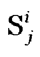
- S j i represents sample j of chirp i, where i is an integer between 1 and Q.
- a presence score generator 406 determines a score indicative of (e.g., the probability of) whether a target is present in the range zone associated with the respective sinc filter 404. For example, in some embodiments, presence score generator 406 determines the presence score based on the covariance matrix of the range-slow-time data (e.g., 600 or 650) generated by the associated sinc filter 404. For example, in some embodiments, the covariance matrix of the range-slow-time data (e.g., 650) generated by the sinc filter 404 is indicative of how much movement a target experienced in slow-time in the range zone associated with the respective sinc filter 404.
- the norm of such covariance matrix is indicative of the spread of such movement (e.g., indicative of the standard deviation). For example, a higher norm of the covariance matrix is indicative of a higher probability of a human being present at the range zone associated with the respective sinc filter 404 than a lower norm of the covariance matrix.
- the presence score generated by each presence score generator 406 is the norm of the covariance of the range-slow-time data (e.g., 650) generated by the respective sinc filter 404.
- determining the presence score by taking the norm of the covariance matrix of the range-slow-time data generated by the associated sinc filter 404 advantageously results in better target detection (e.g., compared to using the signal energy - amplitude only) due to better signal-to-noise ratio (SNR) of the covariance matrix.
- the use of the norm of the covariance matrix of the range-slow-time data to detect targets also advantageously removes static targets (e.g., such as walls) from the detection (i.e., static targets are not detected) as static targets do not move and, therefore, result in a lower norm.
- a target is detected as present when the presence score (e.g., the norm of the covariance matrix) is higher than a predetermined threshold.
- the presence score e.g., the norm of the covariance matrix
- method 400 also includes N phase difference generators 408 per pair of antennas 216 (N being the number of complex sinc filters 404 per antenna 216). For example, in an embodiment that includes 3 receiving antennas 216, method 400 may include 3*N phase difference generators 408.
- each phase difference generator 408 corresponds to a particular range zone.
- phase difference generator 408 1 corresponds to the range zone associated with complex sinc filter 1
- phase difference generator 408 i corresponds to the range zone associated with complex sinc filter i
- phase difference generator 408 N corresponds to the range zone associated with complex sinc filter N .
- each phase difference generator 408 generates Q synthetic antennas (Q being the number of chirps per frame) based on the phase differences between range slow-time data (e.g., 650) from associated sinc filters 404.
- the Q synthetic antennas are generated by determining the cumulative phase difference for the Q phase differences.
- Figure 7A illustrates a method for determining Q cumulative phase differences (corresponding to the Q synthetic antennas), according to an embodiment of the present invention.
- Q phase differences ⁇ ⁇ i are initially determined by subtracting the phase of range slow-time data from one sinc filter 402 (e.g., the range slow-time data generated by sinc filter 404 M_i ) from the other phase of range slow-time data from one sinc filter 402 (e.g., the range slow-time data generated by sinc filter 404 1_i ).
- Figure 7B illustrates Q synthetic antennas and associated phases, according to an embodiment of the present invention.
- each phase difference generator 408 determines the spatial phase difference between the associated antennas over all samples of the range-slow-time data, and creates synthetic signal with the cumulative sum of phase differences.
- the amplitude of the synthetic antennas is based on the presence score determined by the associated presence score generator 406 (e.g., the maximum of the two associated presence scores, or the average of the two associated presence scores).
- method 400 includes an angle estimator 410 per phase difference generator 408.
- each angle estimator 410 determines the angle of the target based on the respective Q synthetic antennas (e.g., in a known manner) using digital beamforming techniques, such as using FFT, phase monopulse, minimum variance distortionless response (MVDR) beamformer, sinc filters, etc.
- digital beamforming techniques such as using FFT, phase monopulse, minimum variance distortionless response (MVDR) beamformer, sinc filters, etc.
- each angle estimator 410 is indicative of the probability of a target being present in different angle zones of the range zone associated with the respective sinc filter 404.
- Figure 8 shows an occupancy grid map illustrating the different range-angle zones associated with the four non-overlapping sinc filters 404 illustrated in Figures 5A and 5B , according to an embodiment of the present invention.
- the occupancy grid map 412 includes 4 range zones.
- the number of angle zones per range zone may be 3, resulting in a total of 12 range-angle zones in the embodiment illustrated in Figure 8 .
- Higher number of angle zones per range zone e.g., 4, 5, 6, or more
- 2 angle zones per range zone may be used.
- Figure 9 shows a flow chart of embodiment method 900 for target presence detection, according to an embodiment of the present invention.
- method 900 may be performed by processing system 204.
- a radar data frame that includes Q chirps is received, e.g., from millimeter-wave radar sensor 202.
- Q is equal to 32.
- Q is higher than 32, such as 64 or higher.
- Q is lower than 32, such as 16 or lower.
- the radar data frame includes data from two receiving antennas 216. In some embodiments, the radar data frame includes data from mode than two receiving antennas, such as three antennas (e.g., in an L-shape configuration), or more than three antennas.
- a plurality of range-slow-time data is generated by a respective plurality of non-overlapping sinc filters (e.g., 404).
- a presence score is generated (e.g., by presence score generator 406) for each range-slow-time data generated during step 904.
- a presence score is generated for each range zone.
- the presence score for each range zone is generated by averaging the presence scores associated with the same range zone.
- the presence score may be generated by averaging the presence scores generated by presence score generators 406 1_i to 406 M_i ).
- the presence score for each range zone is equal to the presence score generated by a particular presence score generator 406, such as the presence score generator 406 associated with higher the antenna exhibiting higher SNR (e.g., in the range-slow-time data).
- the presence score generated during step 908 is compared with a predetermined threshold. If the presence score is lower than the predetermined threshold (output "no" from step 912), then no target is detected as present in the associated range zone during step 912, and the occupancy grid map (e.g., 412) is updated during step 913, e.g., for all angle zones of the associated range zone, to reflect that no target is detected (e.g., low probability of presence detection) in the angle zones of the associated range zone. As shown by steps 914, the next range zone (if applicable) is evaluated after step 913. In some embodiments, the occupancy grid map is updated to have a probability of 0 for all the angle zones associated with the range zone in which no target is detected.
- the occupancy grid map is updated to have a probability of 0 for all the angle zones associated with the range zone in which no target is detected.
- step 912 If the presence score is higher than the predetermined threshold (output "yes" from step 912), a target has been detected in the associated range zone, and synthetic antennas are generated during step 916 (e.g., using the associated phase difference generator 408) based on the range-slow-time data generated by the sinc filters 402 associated with the range zone, and the angle zone of the detected target is identified during step 918 (e.g., using angle estimator 410) based on the associated synthetic antennas.
- synthetic antennas are generated during step 916 (e.g., using the associated phase difference generator 408) based on the range-slow-time data generated by the sinc filters 402 associated with the range zone, and the angle zone of the detected target is identified during step 918 (e.g., using angle estimator 410) based on the associated synthetic antennas.
- the occupancy map grid (e.g., 412) is updated to reflect the target detection. For example, in some embodiments, the previous presence probability of each angle zone associated with the range zone in which presence is detected is updated with a new presence probability generated during step 918.
- some embodiments advantageously avoid performing steps 916, 918, and 920 when a target is not detected in a particular range zone, thereby advantageously reducing computation complexity, and associated costs (e.g., avoiding use of the associated power consumption, and freeing processing system 204 for performing other tasks).
- method 900 is performed per frame of radar data. Thus, in some embodiments, there is no temporal tracking of whether a target is present or not in each of the range-angle zones.
- temporal modeling is used to smoothen the transition between presence detection states for each range-angle zone of occupancy grid map 412, which may advantageously avoid false positives and improve the performance of the target detection.
- Figure 10 shows a flow chart of embodiment method 1000 for updating occupancy grid map 412, according to an embodiment of the present invention. In some embodiments, steps 913 and 920 may be performed as method 1000.
- method 1000 estimates new occupancy probability for range angle zone i,j based on a previous occupancy probability (e.g., from range angle zone i,j) and a new occupancy probability measurement.
- a new occupancy probability value is received for range-angle zone i,j (where i represents an range index of occupancy grid map 412 and j represents an angle index of occupancy grid 412).
- the received new occupancy probability value may be an output of the associated angle estimator 410.
- the received new occupancy probability value may be an SNR value of the output of the associated angle estimator 410.
- the received new occupancy probability value may be a predetermined value (e.g., 0), such as generated when step 912 outputs "no.”
- a new occupancy probability for range-angle zone i,j is estimated based on the previous occupancy probability and the new occupancy probability value.
- LLR ( i,j ) n +1 represents the log-likelihood ratio for range-angle zone i,j associated with frame n+1
- LLR ( i,j ) n represents the log-likelihood ratio for range-angle zone i,j associated with frame n
- ⁇ is a (e.g., predetermined) factor between 0 and 1 (such as, e.g., 0.5)
- V prob represents a presence probability value (e.g., received during step 1002).
- L ( m 1 ) represents the probability distribution of the range-angle zone in which the presence has been detected (e.g., output of the associated angle estimator 410), and represents the (e.g., predetermined) probability distribution of the range-angle zone when occupancy presence is not detected.
- L ( m 1 ) may be equal to the SNR of the output of the occupancy probability generated by angle estimator 412 and L ( m 1 ) may be equal to the SNR of a predetermined occupancy probability when a target is not present in the range-angle zone i,j.
- some embodiments advantageously slow the transition between a presence detection state (LLR(i,j) greater than a predetermined threshold), and a presence not detected state (LLR(i,j) lower than the predetermined threshold), which may advantageously avoid false positive (e.g., due to noise).
- the presence of a strong target (e.g., a target near millimeter-wave radar sensor 202) in the raw radar data may cause a weak target to be confused with noise and not be detected.
- successive interference cancellation also referred to as SIC
- Figure 11 shows a flow chart of embodiment method 1100 for target presence detection, according to an embodiment of the present invention. In some embodiments, method 1100 may be performed by processing system 204.
- method 1100 is similar to method 900 any may perform steps 902, 904, 906, 908, 912, 916, 918, and 920 in a similar manner as described with respect to method 900.
- Method 1100 instead of iterating through the difference range zones sequentially (e.g., as illustrated by steps 910 and 914 of Figure 9 ), method 1100 iterates through the different range zones based on the associated presence scores (e.g., from higher to lower) and the presence scores are updated after removing from the raw radar data the contributions of the strongest detected target, as illustrated by steps 1110, 1113 and 1114, which are described in more detail below.
- step 1110 the range zone associated with the highest presence score (generated during step 908) is selected.
- step 912 when the selected presence score is lower than the predetermined threshold (output "no"), the occupancy grid is updated during step 1113 (e.g., by performing method 1000) for all angle zones of the selected range zone, as well as for all other range-angle zones not previously updated in the current frame, to reflect that no target is present.
- the selected present score is higher than the predetermined threshold (output "yes"), the range-angle zones associated with the selected range zone are updated by performing steps 916, 918, and 920.
- the contributions associated with the detected target(s) in the selected range zone are removed from the raw radar data.
- the raw radar data e.g., received during step 902
- y h 1 x 1 + h 2 x 2 + ... + h k x k + n
- the estimated strongest target signal the signal of the range zone associated with the highest presence score
- a band stop filter may be used to remove the strongest target signal from the raw radar signal.
- This process is repeated until y ⁇ n where h i k i represents the targets present in the raw radar signal y, where h k k k represents the strongest target present in the raw radar signal y, and n represents noise. In some embodiments, this process is repeated until Equation 8 is true or until a maximum number of iterations (e.g., 3) is reached.
- ⁇ represents the output (e.g., 600) of the complex sinc filter 404 associated with the selected presence score.
- some embodiments are advantageously capable of detecting weak targets in the presence of stronger targets while minimizing the computational complexity (since, once equation 8 becomes true, the output of step 912 becomes "no" and step 1113 is performed).
- Advantages of some embodiments include the ability of performing occupancy detection independent from the amount of people on the scene and/or on the particular range-angle zone, which may advantageously avoid complex target tracking and may be advantageously implemented in a (e.g., embedded) processor with limited memory and computational capacity. Additional advantages include the capability of focusing on static human targets, where only micro movements, like breathing are performed.
- Example 1 A method including: receiving radar digital data; processing the radar digital data with a plurality of sinc filters to generate a respective plurality of range-slow-time data, where each sinc filter is associated with a respective range zone of a plurality of range zones; generating a first presence score indicative of a probability of target presence in a first range zone of the plurality of range zones based on a first range-slow-time data of the plurality of range-slow-time data, where the first range-slow-time data is associated with the first range zone; and when the first presence score is higher than a predetermined threshold, generating a plurality of synthetic antennas based on the first range-slow-time data, performing angle estimation based on the plurality of synthetic antennas to generate first probability values for a plurality of angle zones associated with the first range zone, and updating an occupancy grid map indicative of a probability of target presence in each angle zone of each of the plurality of range zones based on the first probability values.
- Example 2 The method of example 1, where generating the first presence score includes generating the first presence score based on a first covariance matrix of the first range-slow-time data.
- Example 3 The method of one of examples 1 or 2, where generating the first presence score includes computing a norm of the first covariance matrix.
- Example 4 The method of one of examples 1 to 3, where the radar digital data is organized in frames, each frame having Q chirps, Q being a positive integer greater than 1, and where generating the plurality of synthetic antennas includes generating Q synesthetic antennas based on Q phase differences between the first range-slow-time data and a second range-slow-time data, where the first range-slow-time data is associated with a first receiving antenna of a millimeter-wave radar system, and the second range-slow-time data is associated with a second receiving antenna of the millimeter-wave radar system, where the second range-slow-time data is associated with the first range zone.
- Example 5 The method of one of examples 1 to 4, where performing angle estimation includes performing digital beamforming using minimum variance distortionless response (MVDR).
- MVDR minimum variance distortionless response
- Example 6 The method of one of examples 1 to 5, further including: generating a plurality of presence scores based on the plurality of range-slow-time data, the plurality of presence scores including the first presence score, where the first presence score is the highest presence score of the plurality of presence scores, and where the first presence score is higher than the predetermined threshold; subtracting from the radar digital data target data associated with the first presence score to generate updated radar digital data; processing the updated radar digital data with the plurality of sinc filters to generate a further respective plurality of range-slow-time data; generating a further plurality of presence scores based on the further plurality of range-slow-time data; selecting a second range-slow-time data from the further plurality of range slow-time data, the second range-slow-time data having a second presence score, the second presence score being the highest presence score of the further plurality of presence scores, the second range-slow-time data being associated with a second range zone different from the first range zone; and when the second presence score is higher than the predetermined
- Example 7 The method of one of examples 1 to 6, further including, when the second presence score is lower than the predetermined threshold, updating the occupancy grid map to reflect no presence detection in the second range zone.
- Example 8 The method of one of examples 1 to 7, where updating the occupancy grid map is further based on a previous state of the occupancy grid map.
- Example 9 The method of one of examples 1 to 8, where the plurality of sinc filters includes a plurality of non-overlapping complex sinc filters.
- a millimeter-wave radar system including: a millimeter-wave radar sensor configured to transmit radar signals, receive reflected radar signals, and generate radar digital data based on the reflected radar signals; and a processing system configured to: process the radar digital data with a plurality of sinc filters to generate a respective plurality of range-slow-time data, where each sinc filter is associated with a respective range zone of a plurality of range zones, generate a first presence score indicative of a probability of target presence in a first range zone of the plurality of range zones based on a first range-slow-time data of the plurality of range-slow-time data, where the first range-slow-time data is associated with the first range zone, and when the first presence score is higher than a predetermined threshold, generate a plurality of synthetic antennas based on the first range-slow-time data, perform angle estimation based on the plurality of synthetic antennas to generate first probability values for a plurality of angle zones associated with the first range zone, and update an occupancy grid map indicative
- Example 11 The millimeter-wave radar system of example 10, where generating the first presence score includes generating the first presence score based on a first covariance matrix of the first range-slow-time data.
- Example 12 The millimeter-wave radar system of one of examples 10 or 11, where generating the first presence score includes computing a norm of the first covariance matrix.
- Example 13 The millimeter-wave radar system of one of examples 10 to 12, further including first and second receiving antennas configured to receive the reflected radar signals, where the radar digital data is organized in frames, each frame having Q chirps, Q being a positive integer greater than 1, and where generating the plurality of synthetic antennas includes generating Q synesthetic antennas based on Q phase differences between the first range-slow-time data and a second range-slow-time data, where the first range-slow-time data is associated with the first receiving antenna , and the second range-slow-time data is associated with the second receiving antenna, where the second range-slow-time data is associated with the first range zone.
- Example 14 The millimeter-wave radar system of one of examples 10 to 13, further including a third receiving antennas, where the first, second, and third receiving antennas are arranged in an L-shape, where generating the first presence score includes generating the first presence score based on the first and second range-slow-time data, and further based on a third range-slow-time data associated with the third receiving antenna.
- Example 15 The millimeter-wave radar system of one of examples 10 to 14, where updating the occupancy grid map is further based on a previous state of the occupancy grid map.
- Example 16 The millimeter-wave radar system of one of examples 10 to 15, where the plurality of sinc filters is a plurality of non-overlapping complex sinc filters.
- Example 17 A method including: receiving a first frame of radar digital data, the first frame including Q chirps, Q being aa positive integer greater than 1, the first frame including first and second data from first and second receiving antennas of a millimeter-wave radar system, respectively; processing the first data with a first plurality of sinc filters to generate a respective first plurality of range-slow-time data, where each sinc filter of the first plurality of sinc filters is associated with a respective range zone of a plurality of range zones; processing the second data with a second plurality of sinc filters to generate a respective second plurality of range-slow-time data, where each sinc filter of the second plurality of sinc filters has a corresponding sinc filter of the first plurality of sinc filters; generating a first presence score indicative of a probability of target presence in a first range zone of the plurality of range zones based on a first range-slow-time data of the first plurality of range-slow-time data or on a second range-slow-time
- Example 18 The method of example 17, further including receiving a second frame of radar digital data before receiving the first frame, where updating the occupancy grid map is further based on the second frame.
- Example 19 The method of one of examples 17 or 18, where updating the occupancy grid map is based on a signal-to-noise ratio (SNR) associated with the first probability values.
- SNR signal-to-noise ratio
- Example 20 The method of one of examples 17 to 19, where generating the plurality of synthetic antennas includes generating the plurality of synthetic antennas based on cumulative sums of phase differences between the first and second range-slow-time data.
Landscapes
- Engineering & Computer Science (AREA)
- Remote Sensing (AREA)
- Radar, Positioning & Navigation (AREA)
- Physics & Mathematics (AREA)
- Computer Networks & Wireless Communication (AREA)
- General Physics & Mathematics (AREA)
- Electromagnetism (AREA)
- Radar Systems Or Details Thereof (AREA)
Abstract
Description
- The present disclosure relates generally to an electronic system and method, and, in particular embodiments, to a radar-based segmented presence detection.
- Applications in the millimeter-wave frequency regime have gained significant interest in the past few years due to the rapid advancement in low-cost semiconductor technologies, such as silicon germanium (SiGe) and fine geometry complementary metal-oxide semiconductor (CMOS) processes. Availability of high-speed bipolar and metal-oxide semiconductor (MOS) transistors has led to a growing demand for integrated circuits for millimeter-wave applications at e.g., 24 GHz, 60 GHz, 77 GHz, and 80 GHz and also beyond 100 GHz. Such applications include, for example, automotive radar systems and multi-gigabit communication systems.
- In some radar systems, the distance between the radar and a target is determined by transmitting a frequency modulated signal, receiving a reflection of the frequency modulated signal (also referred to as the echo), and determining a distance based on a time delay and/or frequency difference between the transmission and reception of the frequency modulated signal. Accordingly, some radar systems include a transmitting antenna for transmitting the radio-frequency (RF) signal, and a receiving antenna for receiving the reflected RF signal, as well as the associated RF circuits used to generate the transmitted signal and to receive the RF signal. In some radar systems, multiple antennas may be used to implement directional beams using phased array techniques. A multiple-input and multiple-output (MIMO) configuration with multiple chipsets can be used to perform coherent and non-coherent signal processing.
-
Figure 1 illustrates a flow chart ofexemplary method 100 for target detection based on radar data. - During
step 102, a range fast Fourier transform (FFT) is performed on the raw radar data for each receiving antenna of the radar. For example, a windowed FFT having a length of a chirp is calculated for each of the chirps in a frame. The result of the range FFT is an indication of energy distribution across ranges for each chirp. - During
step 104, for each receiving antenna, a Doppler FFT is performed on the range FFT data. For example, an FFT is calculated across each range bin over a number of consecutive periods to extract Doppler information. The result ofstep 104 is a range Doppler maps (also known are range-Doppler image or RDI) for each of the receiving antennas. - During
step 106, two-dimensional (2D) moving target indication (MTI) filtering is applied to each RDI to generate filtered images. Performing MTI filtering serves to discriminate a target against the clutter (e.g., only targets with, e.g., high motion are retained as their energy varies across Doppler images). Thus, after 2D MTI filtering, a target may be identifiable in the filtered RDls while information about the background may be partially or fully removed from the filtered RDls. - During
step - During
step 110, target detection is performed using an order statistics (OS) constant false alarm rate (CFAR) (OS-CFAR) detector, in which the CFAR detector compares the power levels of the RAI with a threshold, and points above the threshold are labeled as targets while points below the threshold are labeled as non-targets. - A method as defined in
claim 1 and a millimeter-wave radar system as defined in claim 10 are provided. The dependent claims define further embodiments. - In accordance with an embodiment, a method includes: receiving radar digital data; processing the radar digital data with a plurality of sinc filters to generate a respective plurality of range-slow-time data, where each sinc filter is associated with a respective range zone of a plurality of range zones; generating a first presence score indicative of a probability of target presence in a first range zone of the plurality of range zones based on a first range-slow-time data of the plurality of range-slow-time data, where the first range-slow-time data is associated with the first range zone; and when the first presence score is higher than a predetermined threshold, generating a plurality of synthetic antennas based on the first range-slow-time data, performing angle estimation based on the plurality of synthetic antennas to generate first probability values for a plurality of angle zones associated with the first range zone, and updating an occupancy grid map indicative of a probability of target presence in each angle zone of each of the plurality of range zones based on the first probability values.
- In accordance with an embodiment, a millimeter-wave radar system includes: a millimeter-wave radar sensor configured to transmit radar signals, receive reflected radar signals, and generate radar digital data based on the reflected radar signals; and a processing system configured to: process the radar digital data with a plurality of sinc filters to generate a respective plurality of range-slow-time data, where each sinc filter is associated with a respective range zone of a plurality of range zones, generate a first presence score indicative of a probability of target presence in a first range zone of the plurality of range zones based on a first range-slow-time data of the plurality of range-slow-time data, where the first range-slow-time data is associated with the first range zone, and when the first presence score is higher than a predetermined threshold, generate a plurality of synthetic antennas based on the first range-slow-time data, perform angle estimation based on the plurality of synthetic antennas to generate first probability values for a plurality of angle zones associated with the first range zone, and update an occupancy grid map indicative of a probability of target presence in each angle zone of each of the plurality of range zones based on the first probability values.
- In accordance with an embodiment, a method includes: receiving a first frame of radar digital data, the first frame including Q chirps, Q being aa positive integer greater than 1, the first frame including first and second data from first and second receiving antennas of a millimeter-wave radar system, respectively; processing the first data with a first plurality of sinc filters to generate a respective first plurality of range-slow-time data, where each sinc filter of the first plurality of sinc filters is associated with a respective range zone of a plurality of range zones; processing the second data with a second plurality of sinc filters to generate a respective second plurality of range-slow-time data, where each sinc filter of the second plurality of sinc filters has a corresponding sinc filter of the first plurality of sinc filters; generating a first presence score indicative of a probability of target presence in a first range zone of the plurality of range zones based on a first range-slow-time data of the first plurality of range-slow-time data or on a second range-slow-time data of the second plurality of range-slow-time data, where the first range-slow-time data is associated with the first range zone and the second range-slow-time data is associated with the first range zone; and when the first presence score is higher than a predetermined threshold, generating a plurality of synthetic antennas based on the first and second range-slow-time data, performing angle estimation based on the plurality of synthetic antennas to generate first probability values for a plurality of angle zones associated with the first range zone, and updating an occupancy grid map indicative of a probability of target presence in each angle zone of each of the plurality of range zones based on the first probability values.
- For a more complete understanding of the present invention, and the advantages thereof, reference is now made to the following descriptions taken in conjunction with the accompanying drawings, in which:
-
Figure 1 illustrates a flow chart of an exemplary method for target detection based on radar data; -
Figure 2 shows a schematic diagram of a millimeter-wave radar system, according to an embodiment of the present invention; -
Figure 3 illustrates a sequence of chirps transmitted by the TX antenna ofFigure 2 , according to an embodiment of the present invention; -
Figure 4 shows a flow chart of an embodiment method for target detection based on radar data, according to an embodiment of the present invention; -
Figures 5A and 5B illustrate the frequency response of four non-overlapping sinc filters, and associated range zones, respectively, according to an embodiment of the present invention; -
Figures 6A and 6B illustrate possible outputs of a complex sinc filter ofFigure 4 , according to embodiments of the present invention; -
Figure 7A illustrates a method for determining synthetic antennas, according to an embodiment of the present invention; -
Figure 7B illustrates the Q synthetic antennas ofFigure 7A , according to an embodiment of the present invention; -
Figure 8 illustrates an occupancy grid map associated with the four non-overlapping sinc filters 404 illustrated inFigures 5A and 5B , according to an embodiment of the present invention; -
Figure 9 shows a flow chart of an embodiment method for target presence detection, according to an embodiment of the present invention; -
Figure 10 shows a flow chart of an embodiment method for an updating occupancy grid map, according to an embodiment of the present invention; and -
Figure 11 shows a flow chart of an embodiment method for target presence detection, according to an embodiment of the present invention. - Corresponding numerals and symbols in different figures generally refer to corresponding parts unless otherwise indicated. The figures are drawn to clearly illustrate the relevant aspects of the preferred embodiments and are not necessarily drawn to scale.
- The making and using of the embodiments disclosed are discussed in detail below. It should be appreciated, however, that the present invention provides many applicable inventive concepts that can be embodied in a wide variety of specific contexts. The specific embodiments discussed are merely illustrative of specific ways to make and use the invention, and do not limit the scope of the invention.
- The description below illustrates the various specific details to provide an in-depth understanding of several example embodiments according to the description. The embodiments may be obtained without one or more of the specific details, or with other methods, components, materials and the like. In other cases, known structures, materials or operations are not shown or described in detail so as not to obscure the different aspects of the embodiments. References to "an embodiment" in this description indicate that a particular configuration, structure or feature described in relation to the embodiment is included in at least one embodiment. Consequently, phrases such as "in one embodiment" that may appear at different points of the present description do not necessarily refer exactly to the same embodiment. Furthermore, specific formations, structures or features may be combined in any appropriate manner in one or more embodiments.
- Embodiments of the present invention will be described in specific contexts, e.g., a millimeter-wave radar system capable of providing segmented presence detection, e.g., for human target detection. Embodiments of the present invention may be used for other types of targets (e.g., animals, robots, etc.). Some embodiments may operate in regimes different from millimeter-wave.
- In an embodiment of the present invention, a plurality of non-overlapping sinc filters is used for each receiving antenna of a millimeter-wave radar to generate a corresponding plurality of time-domain I/Q data. A presence score is determined based on slow-time data from the sinc filters to determine target presence at the ranges corresponding to the sinc filters. Angle estimation is determined for the ranges in which a target has been detected to determine the range-angle zone at which the target is present. In some embodiments, using segmented target presence advantageously allows for accurate target detection while minimizing computational complexity. In some embodiments, successive interference cancellation may be used to advantageously perform target detection for ranges associated with weak targets as well as to prevent further processing for ranges in which a target is not detected. In some embodiments, temporal modeling is used to track target presence at each range-angle zone, which may advantageously avoid false positives.
-
Figure 2 shows a schematic diagram of millimeter-wave radar system 200, according to an embodiment of the present invention. Millimeter-wave radar system 200 includes millimeter-wave radar sensor 202 andprocessing system 204. - During normal operation, millimeter-
wave radar sensor 202 operates as a frequency-modulated continuous-wave (FMCW) radar sensor and transmits a plurality of TX radar signals 206, such as chirps, e.g., organized in frames, towardsscene 220 using one or more transmitter (TX) antenna(s) 214. The radar signals 206 are generated using RF andanalog circuits 230. The radar signals 206 may be, e.g., in the 20 GHz to 122 GHz range. Other frequencies may also be used. - The objects in
scene 220 may include one or more static or moving objects, such as tables, walls, chairs, etc., idle and moving humans and animals, as well as periodically-moving objects, such as rotating fans. Other objects may also be present inscene 220. - The radar signals 206 are reflected by objects in
scene 220. The reflected radar signals 208, which are also referred to as the echo signal, are received by a plurality of receiving (RX)antennas 216. RF andanalog circuits 230 processes the received reflected radar signals 208 using, e.g., band-pass filters (BPFs), low-pass filters (LPFs), mixers, low-noise amplifier (LNA), and/or intermediate frequency (IF) amplifiers in ways known in the art to generate an analog signal xout (t) per receivingantenna 216. - The analog signals xout (t) are converted to raw digital data xout_dig (n) using analog-to-digital converter (ADC) 212. In some embodiments, the raw digital data xout_dig (n) is processed by processing
system 204 to determine whether a particular range-angle zone includes a target. -
Controller 210 controls one or more circuits of millimeter-wave radar sensor 202, such as RF andanalog circuit 230 and/orADC 212.Controller 210 may be implemented, e.g., as a custom digital or mixed signal circuit, for example.Controller 210 may also be implemented in other ways, such as using a general-purpose processor or controller, for example. In some embodiments,processing system 204 implements a portion or all ofcontroller 210. -
Processing system 204 may be implemented with a general-purpose processor, controller or digital signal processor (DSP) that includes, for example, combinatorial circuits coupled to a memory. In some embodiments,processing system 204 may be implemented as an application specific integrated circuit (ASIC). In some embodiments,processing system 104 may be implemented with an ARM, RISC, or x86 architecture, for example. In some embodiments,processing system 204 may include an artificial intelligence (Al) accelerator. Some embodiments may use a combination of hardware accelerator and software running on a DSP or general-purpose microcontroller. Other implementations are also possible. - In some embodiments, millimeter-
wave radar sensor 202 and a portion or all ofprocessing system 204 may be implemented inside the same integrated circuit (IC). For example, in some embodiments, millimeter-wave radar sensor 202 and a portion or all ofprocessing system 204 may be implemented in respective semiconductor substrates that are integrated in the same package. In other embodiments, millimeter-wave radar sensor 202 and a portion or all ofprocessing system 204 may be implemented in the same monolithic semiconductor substrate. In some embodiments, millimeter-wave radar sensor 202 andprocessing system 204 are implemented in respective integrated circuits. In some embodiments, a plurality of integrated circuits is used to implement millimeter-wave radar sensor 202. In some embodiments, a plurality of integrated circuits is used to implementprocessing system 204. Other implementations are also possible. - As a non-limiting example, RF and
analog circuits 230 may be implemented, e.g., as shown inFigure 2 . During normal operation, voltage-controlled oscillator (VCO) 236 generates radar signals, such as a linear frequency chirps (e.g., from 57 GHz to 64 GHz, or from 76 GHz to 77 GHz), which are transmitted by transmittingantenna 214. TheVCO 236 is controlled byPLL 234, which receives a reference clock signal (e.g., 80 MHz) fromreference oscillator 232.PLL 234 is controlled by a loop that includesfrequency divider 238 andamplifier 240. Amplifier 237 may be used to drive transmittingantenna 214. - The TX radar signals 206 transmitted by transmitting
antenna 214 are reflected by objects inscene 220 and received by receivingantennas 216. The echo received by receivingantennas 216 are mixed with a replica of the signal transmitted by transmittingantenna 214 usingrespective mixers 246 to produce respective intermediate frequency (IF) signals xIF (t) (also known as beat signals). In some embodiments, the beat signals xIF (t) have a bandwidth between 10 kHz and 1 MHz. Beat signals with a bandwidth lower than 10 kHz or higher than 1 MHz is also possible.Respective amplifiers 245 may be used to receive the reflected radar signals fromantennas 216. - Beat signals xIF (t) may be respectively filtered with respective low-pass filters (LPFs) 248 and then sampled by
ADC 212.ADC 212 is advantageously capable of sampling the filtered beat signals xout (t) with a sampling frequency that is much smaller than the frequency of the signal received by receivingantennas 216. Using FMCW radars, therefore, advantageously allows for a compact and low-cost implementation ofADC 212, in some embodiments. - The raw digital data xout_dig (n) (also referred to as raw radar data), which in some embodiments include the digitized version of the filtered beat signals xout (t), is (e.g., temporarily) stored, e.g., in matrices of Nc x Ns per receiving
antenna 216, where Nc is the number of chirps considered in a frame and Ns is the number of transmit samples per chirp, for further processing byprocessing system 204. - In some embodiments,
ADC 212 is a 12-bit ADC with multiple inputs. ADCs with higher resolution, such as 14-bits or higher, or with lower resolution, such as 10-bits, or lower, may also be used. In some embodiments, an ADC per receiver antenna may be used. Other implementations are also possible. - As shown in
Figure 2 , only one receivingantenna 216 is illustrated for clarity purposes. In some embodiments, millimeter-wave radar system 200 includes two receivingantennas 216. In some embodiments, millimeter-wave radar system 200 includes three receiving antennas 216 (e.g., arranged in an L-shape, e.g., to capture azimuth and elevation, in addition to range). Other implementations are also possible. -
Figure 3 illustrates a sequence ofchirps 206 transmitted byTX antenna 214, according to an embodiment of the present invention. As shown byFigure 3 , chirps 206 are organized in a plurality of frames (also referred to as physical frames) and may be implemented as up-chirps. Some embodiments may use down-chirps or a combination of up-chirps and down-chirps, such as up-down chirps and down-up chirps. Other waveform shapes may also be used. - As shown in
Figure 3 , each frame may include a plurality of chirps 206 (also referred to, generally, as pulses). For example, in some embodiments, the number of chirps in a frame is 32. Some embodiments may include more than 32 chirps per frame, such as 64 chirps, 96 chirps, 128 chirps, or more, or less than 32 chirps per frame, such as 16 chirps, 8 chirps, or less. - In some embodiments, frames are repeated every FT time. In some embodiments, FT time is 50 ms. A different FT time may also be used, such as more than 50 ms, such as 60 ms, 100 ms, 200 ms, or more, or less than 50 ms, such as 45 ms, 40 ms, or less.
- In some embodiments, the FT time is selected such that the time between the beginning of the last chirp of frame n and the beginning of the first chirp of frame n+1 is equal to PRT. Other embodiments may use or result in a different timing.
- The time between chirps of a frame is generally referred to as pulse repetition time (PRT). In some embodiments, the PRT is 5 ms. A different PRT may also be used, such as less than 5 ms, such as 4 ms, 2 ms, 0.5 ms, or less, or more than 5 ms, such as 6 ms, or more.
- The duration of the chirp (from start to finish) is generally referred to as chirp time (CT). In some embodiments, the chirp time may be, e.g., 64 µs. Higher chirp times, such as 128 µs, or higher, may also be used. Lower chirp times, may also be used.
- In some embodiments, the chirp bandwidth may be, e.g., 4 GHz. Higher bandwidth, such as 6 GHz or higher, or lower bandwidth, such as 2 GHz, 1 GHz, or lower, may also be possible.
- In some embodiments, the sampling frequency of millimeter-
wave radar sensor 202 may be, e.g., 1 MHz. Higher sampling frequencies, such as 2 MHz or higher, or lower sampling frequencies, such as 500 kHz or lower, may also be possible. - In some embodiments, the number of samples used to generate each chirp may be, e.g., 64 samples. A higher number of samples, such as 128 samples, or higher, or a lower number of samples, such as 32 samples or lower, may also be used to generate each chirp.
-
Figure 4 shows a block diagram ofembodiment method 400 for target detection based on radar data, according to an embodiment of the present invention. In some embodiments,method 400 may be implemented by processingsystem 204.Figure 4 may be understood in view ofFigures 5A, 5B, 6A, 6B, 7A , and7B . - As shown in
Figure 4 ,method 400 includes range presence detector 402 per receivingantenna 216. Each range presence detector 402 includes N non-overlapping complex sinc filters 404 and respective presence score generator 406. For clarity purposes, the description below assumes that M is equal to 2 (the processing is performed with data from two receiving antennas 216). - In some embodiments, each filter 404x_i is identical. For example, in some embodiments, each of filters 4041_1 to 404M_1 (also referred in
Figure 4 as complex sinc filter 1) are equal and correspond to the same range zone. For example,Figures 5A and 5B illustrate the frequency response of 4 non-overlapping sinc filters 404, and associated range zones, respectively, according to an embodiment of the present invention. - As shown in
Figure 5A , in some embodiments, each range presence detector 402 includes 4 non-overlapping complex sinc filters 404, where each sinc filter 404 is associated with a different range zone. For example, in some embodiments, filter1 is associated withrange zone 1, filter2 is associated withrange zone 2, filters is associated withrange zone 3, and filters is associated withrange zone 4, as illustrated inFigure 5B . - In some embodiments, using complex sinc filters instead of a range FFT advantageously allows for detecting targets in a range zone with lower computational complexity.
- In some embodiments, the output of each sinc filter 404 is filtered time-domain data. For example,
Figure 6A illustrates time-domain data 600 generated by a complex sinc filter 404, according to an embodiment of the present invention. As shown inFigure 6A , in an embodiment in which each frame includes Q chirps and each chirp includes P samples, complex sinc filter 404 generates a matrix that includes PxQ complex I/Q data points. - In some embodiments, a complex sinc filter 404 further processes the time-
domain data 600 to generate slow-time data, which may advantageously reduce the computational complexity and memory usage (e.g., since only the accumulateddata 650 is stored instead of thedata 600, and the computation is performed using such smaller data set) while retaining enough information for target detection in the respective range zone. For example, in some embodiments, the slow-time data (also referred to as range-slow-time data) generated by a complex sinc filter 404 includes Q complex I/Q data points (Q being the number of chirps per frame), each including the accumulated energy of the respective chirp of the frame. - In some embodiments, each complex sinc filter 404 generates processed fast time data that retains range specific information while keeping the slow time data intact.
- In some embodiments, each complex sinc filter 404 includes a sinc filter with a filter length (also know as number of taps) of P, and a pointwise multiplication occurs with a subsequent summation of all resulting complex values.
- In some embodiments, each complex sinc filter 404 generates the range-slow-time data by multiplying a sinc filter times a chirp, and accumulating the result for each of the Q chirps in a frame. For example,
Figure 6B illustrates complex range-slow-time data generated by a complex sinc filter 404, according to an embodiment of the present invention. As shown inFigure 6B , in an embodiment in which each frame includes Q chirps, complex sinc filter 404 may generate slow-time data 650, which includes Q complex data points. In some embodiments, filtered data point Sfc1 may be given by

chirp 1. - More generally, filtered data point Sfci may be given by

- As shown in
Figure 4 , in some embodiments, for each sinc filter 404, a presence score generator 406 determines a score indicative of (e.g., the probability of) whether a target is present in the range zone associated with the respective sinc filter 404. For example, in some embodiments, presence score generator 406 determines the presence score based on the covariance matrix of the range-slow-time data (e.g., 600 or 650) generated by the associated sinc filter 404. For example, in some embodiments, the covariance matrix of the range-slow-time data (e.g., 650) generated by the sinc filter 404 is indicative of how much movement a target experienced in slow-time in the range zone associated with the respective sinc filter 404. The norm of such covariance matrix is indicative of the spread of such movement (e.g., indicative of the standard deviation). For example, a higher norm of the covariance matrix is indicative of a higher probability of a human being present at the range zone associated with the respective sinc filter 404 than a lower norm of the covariance matrix. Thus, in some embodiments, the presence score generated by each presence score generator 406 is the norm of the covariance of the range-slow-time data (e.g., 650) generated by the respective sinc filter 404. - In some embodiments, determining the presence score by taking the norm of the covariance matrix of the range-slow-time data generated by the associated sinc filter 404 advantageously results in better target detection (e.g., compared to using the signal energy - amplitude only) due to better signal-to-noise ratio (SNR) of the covariance matrix. In some embodiments, the use of the norm of the covariance matrix of the range-slow-time data to detect targets also advantageously removes static targets (e.g., such as walls) from the detection (i.e., static targets are not detected) as static targets do not move and, therefore, result in a lower norm.
- In some embodiments, a target is detected as present when the presence score (e.g., the norm of the covariance matrix) is higher than a predetermined threshold.
- In some embodiments,
method 400 also includes Nphase difference generators 408 per pair of antennas 216 (N being the number of complex sinc filters 404 per antenna 216). For example, in an embodiment that includes 3 receivingantennas 216,method 400 may include 3*Nphase difference generators 408. - In some embodiments, each
phase difference generator 408 corresponds to a particular range zone. For example,phase difference generator 4081 corresponds to the range zone associated with complex sinc filter1,phase difference generator 408i corresponds to the range zone associated with complex sinc filteri, andphase difference generator 408N corresponds to the range zone associated with complex sinc filterN. - In some embodiments, each
phase difference generator 408 generates Q synthetic antennas (Q being the number of chirps per frame) based on the phase differences between range slow-time data (e.g., 650) from associated sinc filters 404. For example, in some embodiments, the Q synthetic antennas are generated by determining the cumulative phase difference for the Q phase differences. For example,Figure 7A illustrates a method for determining Q cumulative phase differences (corresponding to the Q synthetic antennas), according to an embodiment of the present invention. - As shown in
Figure 7A , Q phase differences Δϕi are initially determined by subtracting the phase of range slow-time data from one sinc filter 402 (e.g., the range slow-time data generated by sinc filter 404M_i) from the other phase of range slow-time data from one sinc filter 402 (e.g., the range slow-time data generated by sinc filter 4041_i). As shown inFigure 7A , the Q synthetic antennas Δφi are then determined by the cumulative phase difference of all preceding phase differences, such that the first synthetic antenna φ 1 = Δϕ 1, the second synthetic antennas φ 2 = Δϕ 1 + Δϕ 2 , the ith synthetic antenna

Figure 7B illustrates Q synthetic antennas and associated phases, according to an embodiment of the present invention. - Thus, in some embodiments, each
phase difference generator 408 determines the spatial phase difference between the associated antennas over all samples of the range-slow-time data, and creates synthetic signal with the cumulative sum of phase differences. In some embodiments, the amplitude of the synthetic antennas is based on the presence score determined by the associated presence score generator 406 (e.g., the maximum of the two associated presence scores, or the average of the two associated presence scores). - As shown in
Figure 4 , in some embodiments,method 400 includes anangle estimator 410 perphase difference generator 408. In some embodiments, eachangle estimator 410 determines the angle of the target based on the respective Q synthetic antennas (e.g., in a known manner) using digital beamforming techniques, such as using FFT, phase monopulse, minimum variance distortionless response (MVDR) beamformer, sinc filters, etc. - In some embodiments, the output of each
angle estimator 410 is indicative of the probability of a target being present in different angle zones of the range zone associated with the respective sinc filter 404. In some embodiments, the outputs of allangle estimators 410 associated with a pair of antennas as integrated into anoccupancy grid map 412 indicative of the probability of a target being present in the different range-angle zones. For example,Figure 8 shows an occupancy grid map illustrating the different range-angle zones associated with the four non-overlapping sinc filters 404 illustrated inFigures 5A and 5B , according to an embodiment of the present invention. - As shown in
Figure 8 , in an embodiment having four non-overlapping sinc filters 402, theoccupancy grid map 412 includes 4 range zones. As also illustrated inFigure 8 , in some embodiments, the number of angle zones per range zone may be 3, resulting in a total of 12 range-angle zones in the embodiment illustrated inFigure 8 . Higher number of angle zones per range zone (e.g., 4, 5, 6, or more) may be used. In some embodiments, 2 angle zones per range zone may be used. -
Figure 9 shows a flow chart ofembodiment method 900 for target presence detection, according to an embodiment of the present invention. In some embodiments,method 900 may be performed byprocessing system 204. - During
step 902, a radar data frame that includes Q chirps is received, e.g., from millimeter-wave radar sensor 202. In some embodiments, Q is equal to 32. In some embodiments, Q is higher than 32, such as 64 or higher. In some embodiments, Q is lower than 32, such as 16 or lower. - In some embodiments, the radar data frame includes data from two receiving
antennas 216. In some embodiments, the radar data frame includes data from mode than two receiving antennas, such as three antennas (e.g., in an L-shape configuration), or more than three antennas. - During
step 904, for each receiving antenna data, a plurality of range-slow-time data is generated by a respective plurality of non-overlapping sinc filters (e.g., 404). - During
step 906, a presence score is generated (e.g., by presence score generator 406) for each range-slow-time data generated duringstep 904. - During
step 908, a presence score is generated for each range zone. For example, in some embodiments, the presence score for each range zone is generated by averaging the presence scores associated with the same range zone. For example, for range zone i, the presence score may be generated by averaging the presence scores generated by presence score generators 4061_i to 406M_i). In some embodiments, the presence score for each range zone is equal to the presence score generated by a particular presence score generator 406, such as the presence score generator 406 associated with higher the antenna exhibiting higher SNR (e.g., in the range-slow-time data). - As shown by
steps step 908 is compared with a predetermined threshold. If the presence score is lower than the predetermined threshold (output "no" from step 912), then no target is detected as present in the associated range zone duringstep 912, and the occupancy grid map (e.g., 412) is updated duringstep 913, e.g., for all angle zones of the associated range zone, to reflect that no target is detected (e.g., low probability of presence detection) in the angle zones of the associated range zone. As shown bysteps 914, the next range zone (if applicable) is evaluated afterstep 913. In some embodiments, the occupancy grid map is updated to have a probability of 0 for all the angle zones associated with the range zone in which no target is detected. - If the presence score is higher than the predetermined threshold (output "yes" from step 912), a target has been detected in the associated range zone, and synthetic antennas are generated during step 916 (e.g., using the associated phase difference generator 408) based on the range-slow-time data generated by the sinc filters 402 associated with the range zone, and the angle zone of the detected target is identified during step 918 (e.g., using angle estimator 410) based on the associated synthetic antennas.
- During
step 920, the occupancy map grid (e.g., 412) is updated to reflect the target detection. For example, in some embodiments, the previous presence probability of each angle zone associated with the range zone in which presence is detected is updated with a new presence probability generated duringstep 918. - As shown in
Figure 9 , some embodiments advantageously avoid performingsteps processing system 204 for performing other tasks). - In some embodiments,
method 900 is performed per frame of radar data. Thus, in some embodiments, there is no temporal tracking of whether a target is present or not in each of the range-angle zones. - In some embodiments, temporal modeling is used to smoothen the transition between presence detection states for each range-angle zone of
occupancy grid map 412, which may advantageously avoid false positives and improve the performance of the target detection. For example,Figure 10 shows a flow chart ofembodiment method 1000 for updatingoccupancy grid map 412, according to an embodiment of the present invention. In some embodiments,steps method 1000. - As will be described in more detail below, in some embodiments,
method 1000 estimates new occupancy probability for range angle zone i,j based on a previous occupancy probability (e.g., from range angle zone i,j) and a new occupancy probability measurement. - During
step 1002, a new occupancy probability value is received for range-angle zone i,j (where i represents an range index ofoccupancy grid map 412 and j represents an angle index of occupancy grid 412). In some embodiments, the received new occupancy probability value may be an output of the associatedangle estimator 410. For example, in some embodiments, the received new occupancy probability value may be an SNR value of the output of the associatedangle estimator 410. In some embodiments, the received new occupancy probability value may be a predetermined value (e.g., 0), such as generated whenstep 912 outputs "no." - During
step 1004, a new occupancy probability for range-angle zone i,j is estimated based on the previous occupancy probability and the new occupancy probability value. For example, in some embodiments, the new occupancy probability for range-angle zone i,j may be given by

angle estimator 412 and L(m 1) may be equal to the SNR of a predetermined occupancy probability when a target is not present in the range-angle zone i,j. - As can be seen in
Equations - In some embodiments, the presence of a strong target (e.g., a target near millimeter-wave radar sensor 202) in the raw radar data may cause a weak target to be confused with noise and not be detected. In some embodiments, successive interference cancellation (also referred to as SIC) may be used to remove radar data associated with a detected target from the raw radar data to improve the SNR at other range-zones and increase the changes of detecting weaker target(s) at other range-zones. For example,
Figure 11 shows a flow chart ofembodiment method 1100 for target presence detection, according to an embodiment of the present invention. In some embodiments,method 1100 may be performed byprocessing system 204. - As can be seen in
Figures 9 and11 ,method 1100 is similar tomethod 900 any may performsteps method 900.Method 1100, however, instead of iterating through the difference range zones sequentially (e.g., as illustrated bysteps Figure 9 ),method 1100 iterates through the different range zones based on the associated presence scores (e.g., from higher to lower) and the presence scores are updated after removing from the raw radar data the contributions of the strongest detected target, as illustrated bysteps - During
step 1110, the range zone associated with the highest presence score (generated during step 908) is selected. - As shown by
step 912, when the selected presence score is lower than the predetermined threshold (output "no"), the occupancy grid is updated during step 1113 (e.g., by performing method 1000) for all angle zones of the selected range zone, as well as for all other range-angle zones not previously updated in the current frame, to reflect that no target is present. When the selected present score is higher than the predetermined threshold (output "yes"), the range-angle zones associated with the selected range zone are updated by performingsteps - During
step 1114, the contributions associated with the detected target(s) in the selected range zone are removed from the raw radar data. For example, in some embodiments, if the raw radar data (e.g., received during step 902) is given by

step 1114 by

- In some embodiments, ŷ represents the output (e.g., 600) of the complex sinc filter 404 associated with the selected presence score.
- By performing SIC (e.g., as illustrated
Figure 11 ), some embodiments are advantageously capable of detecting weak targets in the presence of stronger targets while minimizing the computational complexity (since, once equation 8 becomes true, the output ofstep 912 becomes "no" andstep 1113 is performed). - Advantages of some embodiments include the ability of performing occupancy detection independent from the amount of people on the scene and/or on the particular range-angle zone, which may advantageously avoid complex target tracking and may be advantageously implemented in a (e.g., embedded) processor with limited memory and computational capacity. Additional advantages include the capability of focusing on static human targets, where only micro movements, like breathing are performed.
- Example embodiments of the present invention are summarized here. Other embodiments can also be understood from the entirety of the specification and the claims filed herein.
- Example 1. A method including: receiving radar digital data; processing the radar digital data with a plurality of sinc filters to generate a respective plurality of range-slow-time data, where each sinc filter is associated with a respective range zone of a plurality of range zones; generating a first presence score indicative of a probability of target presence in a first range zone of the plurality of range zones based on a first range-slow-time data of the plurality of range-slow-time data, where the first range-slow-time data is associated with the first range zone; and when the first presence score is higher than a predetermined threshold, generating a plurality of synthetic antennas based on the first range-slow-time data, performing angle estimation based on the plurality of synthetic antennas to generate first probability values for a plurality of angle zones associated with the first range zone, and updating an occupancy grid map indicative of a probability of target presence in each angle zone of each of the plurality of range zones based on the first probability values.
- Example 2. The method of example 1, where generating the first presence score includes generating the first presence score based on a first covariance matrix of the first range-slow-time data.
- Example 3. The method of one of examples 1 or 2, where generating the first presence score includes computing a norm of the first covariance matrix.
- Example 4. The method of one of examples 1 to 3, where the radar digital data is organized in frames, each frame having Q chirps, Q being a positive integer greater than 1, and where generating the plurality of synthetic antennas includes generating Q synesthetic antennas based on Q phase differences between the first range-slow-time data and a second range-slow-time data, where the first range-slow-time data is associated with a first receiving antenna of a millimeter-wave radar system, and the second range-slow-time data is associated with a second receiving antenna of the millimeter-wave radar system, where the second range-slow-time data is associated with the first range zone.
- Example 5. The method of one of examples 1 to 4, where performing angle estimation includes performing digital beamforming using minimum variance distortionless response (MVDR).
- Example 6. The method of one of examples 1 to 5, further including: generating a plurality of presence scores based on the plurality of range-slow-time data, the plurality of presence scores including the first presence score, where the first presence score is the highest presence score of the plurality of presence scores, and where the first presence score is higher than the predetermined threshold; subtracting from the radar digital data target data associated with the first presence score to generate updated radar digital data; processing the updated radar digital data with the plurality of sinc filters to generate a further respective plurality of range-slow-time data; generating a further plurality of presence scores based on the further plurality of range-slow-time data; selecting a second range-slow-time data from the further plurality of range slow-time data, the second range-slow-time data having a second presence score, the second presence score being the highest presence score of the further plurality of presence scores, the second range-slow-time data being associated with a second range zone different from the first range zone; and when the second presence score is higher than the predetermined threshold, generating a further plurality of synthetic antennas based on the second range-slow-time data, performing a further angle estimation based on the further plurality of synthetic antennas to generate second probability values for a further plurality of angle zones associated with the second range zone, and updating the occupancy grid map based on the second probability values.
- Example 7. The method of one of examples 1 to 6, further including, when the second presence score is lower than the predetermined threshold, updating the occupancy grid map to reflect no presence detection in the second range zone.
- Example 8. The method of one of examples 1 to 7, where updating the occupancy grid map is further based on a previous state of the occupancy grid map.
- Example 9. The method of one of examples 1 to 8, where the plurality of sinc filters includes a plurality of non-overlapping complex sinc filters.
- Example 10. A millimeter-wave radar system including: a millimeter-wave radar sensor configured to transmit radar signals, receive reflected radar signals, and generate radar digital data based on the reflected radar signals; and a processing system configured to: process the radar digital data with a plurality of sinc filters to generate a respective plurality of range-slow-time data, where each sinc filter is associated with a respective range zone of a plurality of range zones, generate a first presence score indicative of a probability of target presence in a first range zone of the plurality of range zones based on a first range-slow-time data of the plurality of range-slow-time data, where the first range-slow-time data is associated with the first range zone, and when the first presence score is higher than a predetermined threshold, generate a plurality of synthetic antennas based on the first range-slow-time data, perform angle estimation based on the plurality of synthetic antennas to generate first probability values for a plurality of angle zones associated with the first range zone, and update an occupancy grid map indicative of a probability of target presence in each angle zone of each of the plurality of range zones based on the first probability values.
- Example 11. The millimeter-wave radar system of example 10, where generating the first presence score includes generating the first presence score based on a first covariance matrix of the first range-slow-time data.
- Example 12. The millimeter-wave radar system of one of examples 10 or 11, where generating the first presence score includes computing a norm of the first covariance matrix.
- Example 13. The millimeter-wave radar system of one of examples 10 to 12, further including first and second receiving antennas configured to receive the reflected radar signals, where the radar digital data is organized in frames, each frame having Q chirps, Q being a positive integer greater than 1, and where generating the plurality of synthetic antennas includes generating Q synesthetic antennas based on Q phase differences between the first range-slow-time data and a second range-slow-time data, where the first range-slow-time data is associated with the first receiving antenna , and the second range-slow-time data is associated with the second receiving antenna, where the second range-slow-time data is associated with the first range zone.
- Example 14. The millimeter-wave radar system of one of examples 10 to 13, further including a third receiving antennas, where the first, second, and third receiving antennas are arranged in an L-shape, where generating the first presence score includes generating the first presence score based on the first and second range-slow-time data, and further based on a third range-slow-time data associated with the third receiving antenna.
- Example 15. The millimeter-wave radar system of one of examples 10 to 14, where updating the occupancy grid map is further based on a previous state of the occupancy grid map.
- Example 16. The millimeter-wave radar system of one of examples 10 to 15, where the plurality of sinc filters is a plurality of non-overlapping complex sinc filters.
- Example 17. A method including: receiving a first frame of radar digital data, the first frame including Q chirps, Q being aa positive integer greater than 1, the first frame including first and second data from first and second receiving antennas of a millimeter-wave radar system, respectively; processing the first data with a first plurality of sinc filters to generate a respective first plurality of range-slow-time data, where each sinc filter of the first plurality of sinc filters is associated with a respective range zone of a plurality of range zones; processing the second data with a second plurality of sinc filters to generate a respective second plurality of range-slow-time data, where each sinc filter of the second plurality of sinc filters has a corresponding sinc filter of the first plurality of sinc filters; generating a first presence score indicative of a probability of target presence in a first range zone of the plurality of range zones based on a first range-slow-time data of the first plurality of range-slow-time data or on a second range-slow-time data of the second plurality of range-slow-time data, where the first range-slow-time data is associated with the first range zone and the second range-slow-time data is associated with the first range zone; and when the first presence score is higher than a predetermined threshold, generating a plurality of synthetic antennas based on the first and second range-slow-time data, performing angle estimation based on the plurality of synthetic antennas to generate first probability values for a plurality of angle zones associated with the first range zone, and updating an occupancy grid map indicative of a probability of target presence in each angle zone of each of the plurality of range zones based on the first probability values.
- Example 18. The method of example 17, further including receiving a second frame of radar digital data before receiving the first frame, where updating the occupancy grid map is further based on the second frame.
- Example 19. The method of one of examples 17 or 18, where updating the occupancy grid map is based on a signal-to-noise ratio (SNR) associated with the first probability values.
- Example 20. The method of one of examples 17 to 19, where generating the plurality of synthetic antennas includes generating the plurality of synthetic antennas based on cumulative sums of phase differences between the first and second range-slow-time data.
- While this invention has been described with reference to illustrative embodiments, this description is not intended to be construed in a limiting sense. Various modifications and combinations of the illustrative embodiments, as well as other embodiments of the invention, will be apparent to persons skilled in the art upon reference to the description. It is therefore intended that the appended claims encompass any such modifications or embodiments.
Claims (15)
- A method comprising:receiving radar digital data;processing the radar digital data with a plurality of sinc filters to generate a respective plurality of range-slow-time data, wherein each sinc filter is associated with a respective range zone of a plurality of range zones;generating a first presence score indicative of a probability of target presence in a first range zone of the plurality of range zones based on a first range-slow-time data of the plurality of range-slow-time data, wherein the first range-slow-time data is associated with the first range zone; andwhen the first presence score is higher than a predetermined threshold,generating a plurality of synthetic antennas based on the first range-slow-time data,performing angle estimation based on the plurality of synthetic antennas to generate first probability values for a plurality of angle zones associated with the first range zone, andupdating an occupancy grid map indicative of a probability of target presence in each angle zone of each of the plurality of range zones based on the first probability values.
- The method of claim 1, wherein generating the first presence score comprises generating the first presence score based on a first covariance matrix of the first range-slow-time data.
- The method of claim 2, wherein generating the first presence score comprises computing a norm of the first covariance matrix.
- The method of any one of claims 1 to 3, wherein the radar digital data is organized in frames, each frame having Q chirps, Q being a positive integer greater than 1, and wherein generating the plurality of synthetic antennas comprises generating Q synesthetic antennas based on Q phase differences between the first range-slow-time data and a second range-slow-time data, wherein the first range-slow-time data is associated with a first receiving antenna of a millimeter-wave radar system, and the second range-slow-time data is associated with a second receiving antenna of the millimeter-wave radar system, wherein the second range-slow-time data is associated with the first range zone.
- The method of any one of claims 1 to 4, wherein performing angle estimation comprises performing digital beamforming using minimum variance distortionless response (MVDR).
- The method of any one of claims 1 to 5, further comprising:generating a plurality of presence scores based on the plurality of range-slow-time data, the plurality of presence scores comprising the first presence score, wherein the first presence score is the highest presence score of the plurality of presence scores, and wherein the first presence score is higher than the predetermined threshold;subtracting from the radar digital data target data associated with the first presence score to generate updated radar digital data;processing the updated radar digital data with the plurality of sinc filters to generate a further respective plurality of range-slow-time data;generating a further plurality of presence scores based on the further plurality of range-slow-time data;selecting a second range-slow-time data from the further plurality of range slow-time data, the second range-slow-time data having a second presence score, the second presence score being the highest presence score of the further plurality of presence scores, the second range-slow-time data being associated with a second range zone different from the first range zone; andwhen the second presence score is higher than the predetermined threshold,generating a further plurality of synthetic antennas based on the second range-slow-time data,performing a further angle estimation based on the further plurality of synthetic antennas to generate second probability values for a further plurality of angle zones associated with the second range zone, andupdating the occupancy grid map based on the second probability values.
- The method of claim 6, further comprising, when the second presence score is lower than the predetermined threshold, updating the occupancy grid map to reflect no presence detection in the second range zone.
- The method of any one of claims 1 to 7, wherein updating the occupancy grid map is further based on a previous state of the occupancy grid map.
- The method of any one of claims 1 to 8, wherein the plurality of sinc filters comprises a plurality of non-overlapping complex sinc filters.
- A millimeter-wave radar system comprising:a millimeter-wave radar sensor configured to transmit radar signals, receive reflected radar signals, and generate radar digital data based on the reflected radar signals; anda processing system configured to:process the radar digital data with a plurality of sinc filters to generate a respective plurality of range-slow-time data, wherein each sinc filter is associated with a respective range zone of a plurality of range zones,generate a first presence score indicative of a probability of target presence in a first range zone of the plurality of range zones based on a first range-slow-time data of the plurality of range-slow-time data, wherein the first range-slow-time data is associated with the first range zone, andwhen the first presence score is higher than a predetermined threshold,generate a plurality of synthetic antennas based on the first range-slow-time data,perform angle estimation based on the plurality of synthetic antennas to generate first probability values for a plurality of angle zones associated with the first range zone, andupdate an occupancy grid map indicative of a probability of target presence in each angle zone of each of the plurality of range zones based on the first probability values.
- The millimeter-wave radar system of claim 10, wherein generating the first presence score comprises generating the first presence score based on a first covariance matrix of the first range-slow-time data.
- The millimeter-wave radar system of claim 11, wherein generating the first presence score comprises computing a norm of the first covariance matrix.
- The millimeter-wave radar system of any one of claims 10 to 12, further comprising first and second receiving antennas configured to receive the reflected radar signals, wherein the radar digital data is organized in frames, each frame having Q chirps, Q being a positive integer greater than 1, and wherein generating the plurality of synthetic antennas comprises generating Q synesthetic antennas based on Q phase differences between the first range-slow-time data and a second range-slow-time data, wherein the first range-slow-time data is associated with the first receiving antenna , and the second range-slow-time data is associated with the second receiving antenna, wherein the second range-slow-time data is associated with the first range zone.
- The millimeter-wave radar system of claim 13, further comprising a third receiving antennas, wherein the first, second, and third receiving antennas are arranged in an L-shape, wherein generating the first presence score comprises generating the first presence score based on the first and second range-slow-time data, and further based on a third range-slow-time data associated with the third receiving antenna.
- The millimeter-wave radar system of any one of claims 10 to 14,wherein updating the occupancy grid map is further based on a previous state of the occupancy grid map, and /orwherein the plurality of sinc filters is a plurality of non-overlapping complex sinc filters.
Applications Claiming Priority (1)
| Application Number | Priority Date | Filing Date | Title |
|---|---|---|---|
| US17/949,608 US12504526B2 (en) | 2022-09-21 | 2022-09-21 | Radar-based segmented presence detection |
Publications (1)
| Publication Number | Publication Date |
|---|---|
| EP4343368A1 true EP4343368A1 (en) | 2024-03-27 |
Family
ID=88097580
Family Applications (1)
| Application Number | Title | Priority Date | Filing Date |
|---|---|---|---|
| EP23198586.2A Pending EP4343368A1 (en) | 2022-09-21 | 2023-09-20 | Radar-based segmented presence detection |
Country Status (3)
| Country | Link |
|---|---|
| US (1) | US12504526B2 (en) |
| EP (1) | EP4343368A1 (en) |
| CN (1) | CN117741603A (en) |
Families Citing this family (1)
| Publication number | Priority date | Publication date | Assignee | Title |
|---|---|---|---|---|
| CN120741958B (en) * | 2025-08-26 | 2025-12-09 | 湖南坤雷科技有限公司 | Unknown unmanned aerial vehicle signal detection method, unknown unmanned aerial vehicle signal detection device, computer equipment and storage medium |
Citations (1)
| Publication number | Priority date | Publication date | Assignee | Title |
|---|---|---|---|---|
| US20190219687A1 (en) * | 2018-01-16 | 2019-07-18 | Infineon Technologies Ag | System and method for vital signal sensing using a millimeter-wave radar sensor |
Family Cites Families (157)
| Publication number | Priority date | Publication date | Assignee | Title |
|---|---|---|---|---|
| US4241347A (en) | 1978-06-28 | 1980-12-23 | International Telephone And Telegraph Corporation | PRC/FM CW Radar system |
| GB2247799A (en) | 1990-09-04 | 1992-03-11 | Gec Ferranti Defence Syst | Radar based navigation aid |
| US6232922B1 (en) * | 1998-05-12 | 2001-05-15 | Mcintosh John C. | Passive three dimensional track of non-cooperative targets through opportunistic use of global positioning system (GPS) and GLONASS signals |
| US6147572A (en) | 1998-07-15 | 2000-11-14 | Lucent Technologies, Inc. | Filter including a microstrip antenna and a frequency selective surface |
| JP3393204B2 (en) | 1999-10-06 | 2003-04-07 | 株式会社ホンダエレシス | Multi-beam radar device |
| WO2001094975A1 (en) | 2000-06-06 | 2001-12-13 | Altratek Inc. | System and method for detection and tracking of targets |
| DE10037099A1 (en) | 2000-07-28 | 2002-02-07 | Wienand Hans Theo | Personenzählvorrichtung |
| US6622100B2 (en) * | 2001-06-07 | 2003-09-16 | Northrop Grumman Corporation | Hyperspectral analysis tool |
| JP3680029B2 (en) | 2001-08-08 | 2005-08-10 | 三菱重工業株式会社 | Vapor growth method and vapor growth apparatus for metal thin film |
| US7176506B2 (en) | 2001-08-28 | 2007-02-13 | Tessera, Inc. | High frequency chip packages with connecting elements |
| US7948769B2 (en) | 2007-09-27 | 2011-05-24 | Hemisphere Gps Llc | Tightly-coupled PCB GNSS circuit and manufacturing method |
| KR100477647B1 (en) | 2002-06-01 | 2005-03-23 | 삼성전자주식회사 | Motion correction apparatus for image and method thereof |
| US6963259B2 (en) | 2002-06-27 | 2005-11-08 | Harris Corporation | High efficiency resonant line |
| JP3833606B2 (en) | 2002-12-19 | 2006-10-18 | 三菱電機株式会社 | In-vehicle radar system |
| IL154396A0 (en) * | 2002-12-29 | 2009-02-11 | Haim Niv | |
| US7119745B2 (en) | 2004-06-30 | 2006-10-10 | International Business Machines Corporation | Apparatus and method for constructing and packaging printed antenna devices |
| US7317417B2 (en) | 2004-07-12 | 2008-01-08 | Orhan Arikan | Methods for detection and tracking of targets |
| US7057564B2 (en) | 2004-08-31 | 2006-06-06 | Freescale Semiconductor, Inc. | Multilayer cavity slot antenna |
| US7615856B2 (en) | 2004-09-01 | 2009-11-10 | Sanyo Electric Co., Ltd. | Integrated antenna type circuit apparatus |
| US7692684B2 (en) | 2004-09-27 | 2010-04-06 | Point Grey Research Inc. | People counting systems and methods |
| JP2006234513A (en) | 2005-02-23 | 2006-09-07 | Toyota Central Res & Dev Lab Inc | Obstacle detection device |
| US8066642B1 (en) | 2005-05-03 | 2011-11-29 | Sonosite, Inc. | Systems and methods for ultrasound beam forming data control |
| US7596241B2 (en) | 2005-06-30 | 2009-09-29 | General Electric Company | System and method for automatic person counting and detection of specific events |
| US8228382B2 (en) | 2005-11-05 | 2012-07-24 | Ram Pattikonda | System and method for counting people |
| EP1791277A1 (en) | 2005-11-28 | 2007-05-30 | Siemens Aktiengesellschaft | Method and apparatus for transmission path calibration of an antenna system |
| US20070210959A1 (en) | 2006-03-07 | 2007-09-13 | Massachusetts Institute Of Technology | Multi-beam tile array module for phased array systems |
| WO2008094172A2 (en) | 2006-06-01 | 2008-08-07 | University Of Florida Research Foundation, Inc. | Radar microsensor for detection, tracking, and classification |
| US7873326B2 (en) | 2006-07-11 | 2011-01-18 | Mojix, Inc. | RFID beam forming system |
| DE102006032539A1 (en) | 2006-07-13 | 2008-01-17 | Robert Bosch Gmbh | FMCW radar sensor |
| US7889147B2 (en) | 2007-02-23 | 2011-02-15 | Northrop Grumman Systems Corporation | Modular active phased array |
| US7525474B2 (en) | 2007-03-30 | 2009-04-28 | Honeywell International Inc. | Integrated distance measuring equipment and transponder system and method |
| US7675465B2 (en) | 2007-05-22 | 2010-03-09 | Sibeam, Inc. | Surface mountable integrated circuit packaging scheme |
| US8237259B2 (en) | 2007-06-13 | 2012-08-07 | Infineon Technologies Ag | Embedded chip package |
| JP4415040B2 (en) | 2007-09-18 | 2010-02-17 | 三菱電機株式会社 | Radar equipment |
| US7880677B2 (en) | 2007-12-12 | 2011-02-01 | Broadcom Corporation | Method and system for a phased array antenna embedded in an integrated circuit package |
| US8134425B2 (en) | 2007-12-13 | 2012-03-13 | Broadcom Corporation | Method and system for filters embedded in an integrated circuit package |
| US8446312B2 (en) * | 2007-12-25 | 2013-05-21 | Honda Elesys Co., Ltd. | Electronic scanning type radar device, estimation method of direction of reception wave, and program estimating direction of reception wave |
| JP4861303B2 (en) | 2007-12-27 | 2012-01-25 | 株式会社日立製作所 | Radar sensor |
| CA2716958C (en) * | 2008-03-07 | 2014-07-15 | Japan Agency For Marine-Earth Science And Technology | Synthetic aperture processing system and synthetic aperture processing method |
| CN102105810B (en) | 2008-07-24 | 2013-10-23 | 皇家飞利浦电子股份有限公司 | Three-dimensional (3-D) frame capture |
| DE102008054570A1 (en) | 2008-12-12 | 2010-06-17 | Robert Bosch Gmbh | FMCW radar sensor for motor vehicles |
| WO2010092438A1 (en) | 2009-02-13 | 2010-08-19 | Freescale Semiconductor, Inc. | Integrated circuit comprising frequency generation circuitry for controlling a frequency source |
| US20100207805A1 (en) | 2009-02-19 | 2010-08-19 | Agd Systems Limited | Obtaining an indication of a number of moving objects passing speed detection apparatus |
| KR101775572B1 (en) | 2009-04-06 | 2017-09-06 | 콘티 테믹 마이크로일렉트로닉 게엠베하 | Radar system having arrangements and method for decoupling transmission and reception signals and suppression of interference radiation |
| CN201438747U (en) | 2009-05-18 | 2010-04-14 | 幻音科技(深圳)有限公司 | earphones |
| CN101585361A (en) | 2009-05-25 | 2009-11-25 | 郭文艺 | Anti-collision and lane-departure-prevention control device for automobile |
| WO2010147515A1 (en) | 2009-06-17 | 2010-12-23 | Telefonaktiebolage Lm Eriksson (Publ) | A method for antenna calibration in a wideband communication system |
| WO2011004135A1 (en) | 2009-07-07 | 2011-01-13 | Elliptic Laboratories As | Control using movements |
| US9229102B1 (en) | 2009-12-18 | 2016-01-05 | L-3 Communications Security And Detection Systems, Inc. | Detection of movable objects |
| DE102009055262A1 (en) | 2009-12-23 | 2011-06-30 | Endress + Hauser GmbH + Co. KG, 79689 | Method for determining and monitoring the level of a medium in a container according to a transit time measurement method |
| EP2542912A4 (en) | 2010-03-05 | 2014-06-25 | Univ Windsor | RADAR SYSTEM AND METHOD FOR MANUFACTURING THE SAME |
| US8725085B2 (en) | 2010-06-03 | 2014-05-13 | Broadcom Corporation | RF front-end module |
| JP5600499B2 (en) * | 2010-07-01 | 2014-10-01 | 日本電産エレシス株式会社 | Electronic scanning radar apparatus, received wave direction estimation method, and received wave direction estimation program |
| US9569003B2 (en) | 2010-09-30 | 2017-02-14 | Broadcom Corporation | Portable computing device including a three-dimensional touch screen |
| JP5684533B2 (en) * | 2010-10-21 | 2015-03-11 | 日本電産エレシス株式会社 | Electronic scanning radar apparatus, received wave direction estimation method, and received wave direction estimation program |
| JP5549560B2 (en) | 2010-11-26 | 2014-07-16 | 富士通株式会社 | FM-CW radar device and pairing method |
| JP2012168156A (en) | 2011-02-11 | 2012-09-06 | National Univ Corp Shizuoka Univ | Multi-beam type radar apparatus for on-vehicle use, multi-beam type radar method and multi-beam type radar program |
| US8988299B2 (en) | 2011-02-17 | 2015-03-24 | International Business Machines Corporation | Integrated antenna for RFIC package applications |
| US20120280900A1 (en) | 2011-05-06 | 2012-11-08 | Nokia Corporation | Gesture recognition using plural sensors |
| DE102011100907A1 (en) | 2011-05-09 | 2012-01-12 | Daimler Ag | Device for determining road condition of roadway located in front of vehicle, comprises imaging sensor for detecting road surface, and evaluation unit for evaluation of image data |
| DE102011075725A1 (en) | 2011-05-12 | 2012-11-15 | Robert Bosch Gmbh | Method for recognizing gestures |
| US8860532B2 (en) | 2011-05-20 | 2014-10-14 | University Of Central Florida Research Foundation, Inc. | Integrated cavity filter/antenna system |
| US9183686B2 (en) | 2011-07-12 | 2015-11-10 | Tyco Fire & Security Gmbh | Method and system for people counting using passive infrared detectors |
| EP2769477A1 (en) | 2011-10-20 | 2014-08-27 | Keyssa, Inc. | Low-profile wireless connectors |
| WO2013067657A1 (en) * | 2011-11-11 | 2013-05-16 | Telefonaktiebolaget L M Ericsson (Publ) | Method, apparatus and system of antenna array dynamic configuration |
| US20140324888A1 (en) | 2011-12-09 | 2014-10-30 | Nokia Corporation | Method and Apparatus for Identifying a Gesture Based Upon Fusion of Multiple Sensor Signals |
| US9202105B1 (en) | 2012-01-13 | 2015-12-01 | Amazon Technologies, Inc. | Image analysis for user authentication |
| CN102788969B (en) | 2012-07-04 | 2015-01-28 | 中国人民解放军海军航空工程学院 | Sea surface micromotion target detection and feature extraction method based on short-time fractional Fourier transform |
| US9678573B2 (en) | 2012-07-30 | 2017-06-13 | Microsoft Technology Licensing, Llc | Interaction with devices based on user state |
| US20140070994A1 (en) | 2012-09-13 | 2014-03-13 | Toyota Motor Engineering & Manufacturing North America, Inc. | 3d short range detection with phased array radar |
| US9196951B2 (en) | 2012-11-26 | 2015-11-24 | International Business Machines Corporation | Millimeter-wave radio frequency integrated circuit packages with integrated antennas |
| CN102967854B (en) | 2012-12-07 | 2014-08-13 | 中国人民解放军海军航空工程学院 | Multi-fractal detection method of targets in FRFT (Fractional Fourier Transformation) domain sea clutter |
| WO2014104189A1 (en) | 2012-12-26 | 2014-07-03 | 日立化成株式会社 | Expansion method, method for manufacturing semiconductor devices, and semiconductor device |
| US8836596B2 (en) | 2013-01-15 | 2014-09-16 | Cubic Corporation | Filter antenna |
| US9413079B2 (en) | 2013-03-13 | 2016-08-09 | Intel Corporation | Single-package phased array module with interleaved sub-arrays |
| KR101480348B1 (en) | 2013-05-31 | 2015-01-09 | 삼성에스디에스 주식회사 | People Counting Apparatus and Method |
| US9459339B2 (en) | 2013-06-13 | 2016-10-04 | Texas Instruments Incorporated | Kalman filter for indoor positioning |
| CN103529444A (en) | 2013-09-27 | 2014-01-22 | 安徽师范大学 | A vehicle-mounted millimeter-wave radar moving target recognizer and recognition method |
| US9900687B2 (en) | 2013-10-07 | 2018-02-20 | Gn Netcom A/S | Earphone device with optical sensor |
| US9753131B2 (en) | 2013-10-09 | 2017-09-05 | Massachusetts Institute Of Technology | Motion tracking via body radio reflections |
| US9759807B2 (en) | 2013-10-25 | 2017-09-12 | Texas Instruments Incorporated | Techniques for angle resolution in radar |
| US9773742B2 (en) | 2013-12-18 | 2017-09-26 | Intel Corporation | Embedded millimeter-wave phased array module |
| US20150181840A1 (en) | 2013-12-31 | 2015-07-02 | i4c Innovations Inc. | Ultra-Wideband Radar System for Animals |
| JP2015141109A (en) | 2014-01-29 | 2015-08-03 | 富士通テン株式会社 | Radar device and signal processing method |
| US9704769B2 (en) | 2014-02-27 | 2017-07-11 | STATS ChipPAC Pte. Ltd. | Semiconductor device and method of forming encapsulated wafer level chip scale package (EWLCSP) |
| CN203950036U (en) | 2014-03-12 | 2014-11-19 | 肖令军 | A kind of have people's depopulated helicopter anti-collision system based on millimetre-wave radar range finding |
| US9921657B2 (en) | 2014-03-28 | 2018-03-20 | Intel Corporation | Radar-based gesture recognition |
| CN106415454A (en) | 2014-04-30 | 2017-02-15 | Lg伊诺特有限公司 | Touch device, wearable device with the touch device and touch recognition method |
| US9575560B2 (en) | 2014-06-03 | 2017-02-21 | Google Inc. | Radar-based gesture-recognition through a wearable device |
| US9666553B2 (en) | 2014-06-16 | 2017-05-30 | Texas Instruments Incorporated | Millimeter wave integrated circuit with ball grid array package including transmit and receive channels |
| US20170131395A1 (en) | 2014-06-25 | 2017-05-11 | University Of Washington | Devices, systems, and methods for detecting gestures using multiple antennas and/or reflections of signals transmitted by the detecting device |
| US10627480B2 (en) | 2014-07-17 | 2020-04-21 | Texas Instruments Incorporated | Distributed radar signal processing in a radar system |
| US9921660B2 (en) | 2014-08-07 | 2018-03-20 | Google Llc | Radar-based gesture recognition |
| US9811164B2 (en) | 2014-08-07 | 2017-11-07 | Google Inc. | Radar-based gesture sensing and data transmission |
| US10094920B2 (en) | 2014-08-27 | 2018-10-09 | Texas Instruments Incorporated | Range resolution in FMCW radars |
| US9784828B2 (en) | 2014-08-27 | 2017-10-10 | Texas Insturments Incorporated | FMCW doppler processing algorithm for achieving CW performance |
| US9600080B2 (en) | 2014-10-02 | 2017-03-21 | Google Inc. | Non-line-of-sight radar-based gesture recognition |
| US10539669B2 (en) | 2014-10-08 | 2020-01-21 | Texas Instruments Incorporated | Three dimensional (3D) tracking of objects in a radar system |
| US10634778B2 (en) | 2014-10-21 | 2020-04-28 | Texas Instruments Incorporated | Camera assisted tracking of objects in a radar system |
| US20160118353A1 (en) | 2014-10-22 | 2016-04-28 | Infineon Techologies Ag | Systems and Methods Using an RF Circuit on Isolating Material |
| KR20160058594A (en) | 2014-11-17 | 2016-05-25 | 삼성전자주식회사 | Robot cleaner, terminal apparatus and method for controlling thereof |
| US9733340B2 (en) | 2014-11-21 | 2017-08-15 | Texas Instruments Incorporated | Techniques for high arrival angle resolution using multiple nano-radars |
| US9829566B2 (en) | 2014-11-25 | 2017-11-28 | Texas Instruments Incorporated | Controlling radar transmission to enable interference mitigation |
| US10317512B2 (en) | 2014-12-23 | 2019-06-11 | Infineon Technologies Ag | RF system with an RFIC and antenna system |
| US20160306034A1 (en) | 2014-12-23 | 2016-10-20 | Infineon Technologies Ag | RF System with an RFIC and Antenna System |
| US9921295B2 (en) | 2014-12-30 | 2018-03-20 | Texas Instruments Incorporated | Multiple chirp generation in a radar system |
| US9696359B2 (en) | 2014-12-31 | 2017-07-04 | Texas Instruments Incorporated | Dynamic measurement of frequency synthesizer noise spurs or phase noise |
| JP6567832B2 (en) | 2015-01-29 | 2019-08-28 | 日本電産株式会社 | Radar system, radar signal processing apparatus, vehicle travel control apparatus and method, and computer program |
| US10622694B2 (en) | 2015-02-12 | 2020-04-14 | Texas Instruments Incorporated | Dielectric waveguide radar signal distribution |
| US9817109B2 (en) | 2015-02-27 | 2017-11-14 | Texas Instruments Incorporated | Gesture recognition using frequency modulated continuous wave (FMCW) radar with low angle resolution |
| US10481696B2 (en) | 2015-03-03 | 2019-11-19 | Nvidia Corporation | Radar based user interface |
| EP3270762B1 (en) | 2015-03-16 | 2019-01-23 | Duepuntozero S.r.l. | Device for tracheal intubation |
| US10067221B2 (en) | 2015-04-06 | 2018-09-04 | Texas Instruments Incorporated | Interference detection in a frequency modulated continuous wave (FMCW) radar system |
| US9835714B2 (en) | 2015-04-09 | 2017-12-05 | Texas Instruments Incorporated | Circuit and method for impedance detection in millimeter wave systems |
| WO2016176574A1 (en) | 2015-04-30 | 2016-11-03 | Google Inc. | Wide-field radar-based gesture recognition |
| EP3289432B1 (en) | 2015-04-30 | 2019-06-12 | Google LLC | Rf-based micro-motion tracking for gesture tracking and recognition |
| US9853365B2 (en) | 2015-05-05 | 2017-12-26 | Texas Instruments Incorporated | Dynamic programming of chirps in a frequency modulated continuous wave (FMCW) radar system |
| US10613208B2 (en) | 2015-05-15 | 2020-04-07 | Texas Instruments Incorporated | Low complexity super-resolution technique for object detection in frequency modulation continuous wave radar |
| US20160349845A1 (en) | 2015-05-28 | 2016-12-01 | Google Inc. | Gesture Detection Haptics and Virtual Tools |
| US9806040B2 (en) | 2015-07-29 | 2017-10-31 | STATS ChipPAC Pte. Ltd. | Antenna in embedded wafer-level ball-grid array package |
| US10048354B2 (en) | 2015-08-13 | 2018-08-14 | Texas Instruments Incorporated | Chirp frequency non-linearity mitigation in radar systems |
| US12250007B2 (en) | 2015-08-19 | 2025-03-11 | Texas Instruments Incorporated | Method and system for compression of radar signals |
| US10555256B2 (en) | 2015-09-08 | 2020-02-04 | Texas Instruments Incorporated | Re-sampling with reduced power consumption and complexity |
| US10078131B2 (en) | 2015-09-15 | 2018-09-18 | Texas Instruments Incorporated | Method and apparatus for FMCW radar processing |
| US9886095B2 (en) | 2015-09-24 | 2018-02-06 | Stmicroelectronics Sa | Device and method for recognizing hand gestures using time-of-flight sensing |
| US10061015B2 (en) | 2015-09-30 | 2018-08-28 | Texas Instruments Incorporated | Multi-chip transceiver testing in a radar system |
| US10234542B2 (en) | 2015-09-30 | 2019-03-19 | Texas Instruments Incorporated | Measurement of transceiver performance parameters in a radar system |
| US10718852B2 (en) | 2015-10-23 | 2020-07-21 | Texas Instruments Incorporated | RF/mm-wave peak detector with high-dynamic range calibration |
| US9759808B2 (en) | 2015-11-12 | 2017-09-12 | Texas Instruments Incorporated | Buffer sample size control for variable chirp radar |
| WO2017084700A1 (en) | 2015-11-17 | 2017-05-26 | Vega Grieshaber Kg | Antenna system and method for sending and/or receiving a signal |
| KR102427185B1 (en) | 2015-12-09 | 2022-08-01 | 삼성전자 주식회사 | Method for operation of switch and electronic device supporting the same |
| US10746851B2 (en) | 2015-12-18 | 2020-08-18 | Texas Instruments Incorporated | Circuits and methods for determining chirp signal linearity and phase noise of a FMCW radar |
| US10599518B2 (en) | 2015-12-31 | 2020-03-24 | Texas Instruments Incorporated | Protecting data memory in a signal processing system |
| US10530053B2 (en) | 2016-01-13 | 2020-01-07 | Infineon Technologies Ag | System and method for measuring a plurality of RF signal paths |
| US9965043B2 (en) | 2016-01-27 | 2018-05-08 | Wipro Limited | Method and system for recommending one or more gestures to users interacting with computing device |
| US10948580B2 (en) * | 2016-03-15 | 2021-03-16 | Nec Corporation | Object sensing device and object sensing method |
| WO2017165556A1 (en) * | 2016-03-23 | 2017-09-28 | The Regents Of The University Of California | Interference-tolerant multiple-user radar system |
| US10514770B2 (en) | 2016-06-17 | 2019-12-24 | Texas Instruments Incorporated | Hidden Markov model-based gesture recognition with FMCW radar |
| EP3497546B1 (en) | 2016-08-09 | 2021-10-06 | Google LLC | Radar-based gestural interface |
| CN106980362A (en) | 2016-10-09 | 2017-07-25 | 阿里巴巴集团控股有限公司 | Input method and device based on virtual reality scenario |
| US9935065B1 (en) | 2016-12-21 | 2018-04-03 | Infineon Technologies Ag | Radio frequency device packages and methods of formation thereof |
| JP6685941B2 (en) * | 2017-01-05 | 2020-04-22 | 株式会社東芝 | Information processing apparatus, information processing method, and information processing program |
| KR102323655B1 (en) * | 2018-01-08 | 2021-11-09 | 현대모비스 주식회사 | Method and apparatus for estimating direction of arrival using generation of virtual received signals |
| US10795012B2 (en) | 2018-01-22 | 2020-10-06 | Infineon Technologies Ag | System and method for human behavior modelling and power control using a millimeter-wave radar sensor |
| US10564277B2 (en) * | 2018-01-30 | 2020-02-18 | Oculii Corp. | Systems and methods for interpolated virtual aperature radar tracking |
| US10048366B1 (en) * | 2018-01-30 | 2018-08-14 | Oculii Corp | Systems and methods for virtual aperature radar tracking |
| SE1830060A1 (en) * | 2018-02-27 | 2019-08-28 | Qamcom Tech Ab | A radar transceiver with reduced false alarm rate |
| US11187795B2 (en) * | 2018-03-19 | 2021-11-30 | Panasonic Intellectual Property Management Co., Ltd. | Radar device |
| KR102099388B1 (en) * | 2018-05-08 | 2020-04-09 | 서울대학교산학협력단 | Method of estimating direction of arrival of radar signal based on antenna array extrapolation and apparatus for the same |
| US11474225B2 (en) * | 2018-11-09 | 2022-10-18 | Uhnder, Inc. | Pulse digital mimo radar system |
| US11448754B2 (en) * | 2018-11-20 | 2022-09-20 | KMB Telematics, Inc. | Object sensing from a potentially moving frame of reference with virtual apertures formed from sparse antenna arrays |
| US11054516B2 (en) * | 2018-12-18 | 2021-07-06 | Nxp Usa, Inc. | Extended doppler FMCW code division MIMO radar |
| US11099267B2 (en) * | 2018-12-18 | 2021-08-24 | Nxp Usa, Inc. | Extended doppler PMCW code division MIMO radar |
| JP7573926B2 (en) * | 2019-03-20 | 2024-10-28 | パナソニックオートモーティブシステムズ株式会社 | Radar device and transmitting/receiving array antenna |
| CN113495267B (en) * | 2020-04-07 | 2024-06-21 | 北京小米移动软件有限公司 | Radar antenna array, mobile terminal, gesture recognition method and device |
| DE102021112349A1 (en) * | 2020-05-12 | 2021-11-18 | Motional Ad Llc | VEHICLE OPERATION USING A DYNAMIC ALLOCATION GRID |
| US11774553B2 (en) * | 2020-06-18 | 2023-10-03 | Infineon Technologies Ag | Parametric CNN for radar processing |
-
2022
- 2022-09-21 US US17/949,608 patent/US12504526B2/en active Active
-
2023
- 2023-09-20 CN CN202311216761.6A patent/CN117741603A/en active Pending
- 2023-09-20 EP EP23198586.2A patent/EP4343368A1/en active Pending
Patent Citations (1)
| Publication number | Priority date | Publication date | Assignee | Title |
|---|---|---|---|---|
| US20190219687A1 (en) * | 2018-01-16 | 2019-07-18 | Infineon Technologies Ag | System and method for vital signal sensing using a millimeter-wave radar sensor |
Non-Patent Citations (3)
| Title |
|---|
| CHO HYUN-WOONG ET AL: "Complex-Valued Channel Attention and Application in Ego-Velocity Estimation With Automotive Radar", IEEE ACCESS, IEEE, USA, vol. 9, 25 January 2021 (2021-01-25), pages 17717 - 17727, XP011834991, DOI: 10.1109/ACCESS.2021.3054368 * |
| STADELMAYER THOMAS ET AL: "Data-Driven Radar Processing Using a Parametric Convolutional Neural Network for Human Activity Classification", IEEE SENSORS JOURNAL, IEEE, USA, vol. 21, no. 17, 24 June 2021 (2021-06-24), pages 19529 - 19540, XP011875483, ISSN: 1530-437X, [retrieved on 20210830], DOI: 10.1109/JSEN.2021.3092002 * |
| STADELMAYER THOMAS ET AL: "Improved Target Detection and Feature Extraction using a Complex-Valued Adaptive Sine Filter on Radar Time Domain Data", 2021 29TH EUROPEAN SIGNAL PROCESSING CONFERENCE (EUSIPCO), EURASIP, 23 August 2021 (2021-08-23), pages 1745 - 1749, XP034038335, DOI: 10.23919/EUSIPCO54536.2021.9616250 * |
Also Published As
| Publication number | Publication date |
|---|---|
| US20240111040A1 (en) | 2024-04-04 |
| US12504526B2 (en) | 2025-12-23 |
| CN117741603A (en) | 2024-03-22 |
Similar Documents
| Publication | Publication Date | Title |
|---|---|---|
| US11592520B2 (en) | FMCW radar with interfering signal suppression in the time domain | |
| US11693106B2 (en) | Multiple input multiple output (MIMO) frequency-modulated continuous-wave (FMCW) radar system | |
| EP3640675B1 (en) | Estimating angle of a human target using millimeter-wave radar | |
| US11209523B2 (en) | FMCW radar with interference signal rejection | |
| EP4047391B1 (en) | Radar-based target tracker | |
| US11614516B2 (en) | Radar vital signal tracking using a Kalman filter | |
| EP3907523B1 (en) | Radar-based target tracking using motion detection | |
| US8384587B2 (en) | Radar for aerial target detection fitted to an aircraft notably for the avoidance of obstacles in flight | |
| CN110632587A (en) | Weak moving object monitoring method based on rapid FMCW radar | |
| EP4130782A2 (en) | Scene-adaptive radar | |
| Jin et al. | Design and implementation of FMCW surveillance radar based on dual chirps | |
| EP4365623A1 (en) | Radar-based target tracker | |
| US12504526B2 (en) | Radar-based segmented presence detection | |
| US12164056B2 (en) | Context based target detection | |
| Garry et al. | Framework and results on passive ISAR | |
| Mabrouk et al. | A novel algorithm for moving/fixed target discrimination in 77 GHz automotive radars | |
| US20260140251A1 (en) | Radar-based target tracker | |
| US20250283977A1 (en) | Radar device and radar processing method | |
| EP4258008A1 (en) | Adaptive tx-rx crosstalk cancellation for radar systems | |
| Wang et al. | A clutter suppression method for diverse pulse train with different intra-pulse frequency coding | |
| CN118151103A (en) | A transmission waveform group generation method, application method, system and storage medium | |
| Bhise et al. | Implementation of FMCW RADAR using FPGA | |
| Anjum et al. | Target detection and tracking analysis of moving object based on PCLFM simulated model for airborne satellite communication |
Legal Events
| Date | Code | Title | Description |
|---|---|---|---|
| PUAI | Public reference made under article 153(3) epc to a published international application that has entered the european phase |
Free format text: ORIGINAL CODE: 0009012 |
|
| STAA | Information on the status of an ep patent application or granted ep patent |
Free format text: STATUS: THE APPLICATION HAS BEEN PUBLISHED |
|
| AK | Designated contracting states |
Kind code of ref document: A1 Designated state(s): AL AT BE BG CH CY CZ DE DK EE ES FI FR GB GR HR HU IE IS IT LI LT LU LV MC ME MK MT NL NO PL PT RO RS SE SI SK SM TR |
|
| STAA | Information on the status of an ep patent application or granted ep patent |
Free format text: STATUS: REQUEST FOR EXAMINATION WAS MADE |
|
| 17P | Request for examination filed |
Effective date: 20240926 |
|
| RBV | Designated contracting states (corrected) |
Designated state(s): AL AT BE BG CH CY CZ DE DK EE ES FI FR GB GR HR HU IE IS IT LI LT LU LV MC ME MK MT NL NO PL PT RO RS SE SI SK SM TR |
|
| GRAP | Despatch of communication of intention to grant a patent |
Free format text: ORIGINAL CODE: EPIDOSNIGR1 |
|
| STAA | Information on the status of an ep patent application or granted ep patent |
Free format text: STATUS: GRANT OF PATENT IS INTENDED |
|
| INTG | Intention to grant announced |
Effective date: 20260107 |