EP4343349A1 - Apparatus and method for diagnosing abnormality of battery - Google Patents
Apparatus and method for diagnosing abnormality of battery Download PDFInfo
- Publication number
- EP4343349A1 EP4343349A1 EP22899017.2A EP22899017A EP4343349A1 EP 4343349 A1 EP4343349 A1 EP 4343349A1 EP 22899017 A EP22899017 A EP 22899017A EP 4343349 A1 EP4343349 A1 EP 4343349A1
- Authority
- EP
- European Patent Office
- Prior art keywords
- change amount
- capacity difference
- charge
- difference change
- battery
- Prior art date
- Legal status (The legal status is an assumption and is not a legal conclusion. Google has not performed a legal analysis and makes no representation as to the accuracy of the status listed.)
- Granted
Links
Images



Classifications
-
- G—PHYSICS
- G01—MEASURING; TESTING
- G01R—MEASURING ELECTRIC VARIABLES; MEASURING MAGNETIC VARIABLES
- G01R31/00—Arrangements for testing electric properties; Arrangements for locating electric faults; Arrangements for electrical testing characterised by what is being tested not provided for elsewhere
- G01R31/36—Arrangements for testing, measuring or monitoring the electrical condition of accumulators or electric batteries, e.g. capacity or state of charge [SoC]
- G01R31/392—Determining battery ageing or deterioration, e.g. state of health
-
- G—PHYSICS
- G01—MEASURING; TESTING
- G01R—MEASURING ELECTRIC VARIABLES; MEASURING MAGNETIC VARIABLES
- G01R31/00—Arrangements for testing electric properties; Arrangements for locating electric faults; Arrangements for electrical testing characterised by what is being tested not provided for elsewhere
- G01R31/36—Arrangements for testing, measuring or monitoring the electrical condition of accumulators or electric batteries, e.g. capacity or state of charge [SoC]
- G01R31/382—Arrangements for monitoring battery or accumulator variables, e.g. SoC
-
- G—PHYSICS
- G01—MEASURING; TESTING
- G01R—MEASURING ELECTRIC VARIABLES; MEASURING MAGNETIC VARIABLES
- G01R31/00—Arrangements for testing electric properties; Arrangements for locating electric faults; Arrangements for electrical testing characterised by what is being tested not provided for elsewhere
- G01R31/36—Arrangements for testing, measuring or monitoring the electrical condition of accumulators or electric batteries, e.g. capacity or state of charge [SoC]
- G01R31/385—Arrangements for measuring battery or accumulator variables
- G01R31/387—Determining ampere-hour charge capacity or SoC
-
- H—ELECTRICITY
- H01—ELECTRIC ELEMENTS
- H01M—PROCESSES OR MEANS, e.g. BATTERIES, FOR THE DIRECT CONVERSION OF CHEMICAL ENERGY INTO ELECTRICAL ENERGY
- H01M10/00—Secondary cells; Manufacture thereof
- H01M10/42—Methods or arrangements for servicing or maintenance of secondary cells or secondary half-cells
- H01M10/44—Methods for charging or discharging
-
- H—ELECTRICITY
- H01—ELECTRIC ELEMENTS
- H01M—PROCESSES OR MEANS, e.g. BATTERIES, FOR THE DIRECT CONVERSION OF CHEMICAL ENERGY INTO ELECTRICAL ENERGY
- H01M10/00—Secondary cells; Manufacture thereof
- H01M10/42—Methods or arrangements for servicing or maintenance of secondary cells or secondary half-cells
- H01M10/48—Accumulators combined with arrangements for measuring, testing or indicating the condition of cells, e.g. the level or density of the electrolyte
-
- H—ELECTRICITY
- H02—GENERATION; CONVERSION OR DISTRIBUTION OF ELECTRIC POWER
- H02J—ELECTRIC POWER NETWORKS; CIRCUIT ARRANGEMENTS OR SYSTEMS FOR SUPPLYING OR DISTRIBUTING ELECTRIC POWER; SYSTEMS FOR STORING ELECTRIC ENERGY
- H02J7/00—Circuit arrangements for charging or discharging batteries or for supplying loads from batteries
- H02J7/80—Circuit arrangements for charging or discharging batteries or for supplying loads from batteries including monitoring or indicating arrangements
- H02J7/84—Control of state of health [SOH]
-
- G—PHYSICS
- G01—MEASURING; TESTING
- G01R—MEASURING ELECTRIC VARIABLES; MEASURING MAGNETIC VARIABLES
- G01R31/00—Arrangements for testing electric properties; Arrangements for locating electric faults; Arrangements for electrical testing characterised by what is being tested not provided for elsewhere
- G01R31/36—Arrangements for testing, measuring or monitoring the electrical condition of accumulators or electric batteries, e.g. capacity or state of charge [SoC]
- G01R31/382—Arrangements for monitoring battery or accumulator variables, e.g. SoC
- G01R31/3828—Arrangements for monitoring battery or accumulator variables, e.g. SoC using current integration
-
- H—ELECTRICITY
- H02—GENERATION; CONVERSION OR DISTRIBUTION OF ELECTRIC POWER
- H02J—ELECTRIC POWER NETWORKS; CIRCUIT ARRANGEMENTS OR SYSTEMS FOR SUPPLYING OR DISTRIBUTING ELECTRIC POWER; SYSTEMS FOR STORING ELECTRIC ENERGY
- H02J7/00—Circuit arrangements for charging or discharging batteries or for supplying loads from batteries
- H02J7/80—Circuit arrangements for charging or discharging batteries or for supplying loads from batteries including monitoring or indicating arrangements
-
- Y—GENERAL TAGGING OF NEW TECHNOLOGICAL DEVELOPMENTS; GENERAL TAGGING OF CROSS-SECTIONAL TECHNOLOGIES SPANNING OVER SEVERAL SECTIONS OF THE IPC; TECHNICAL SUBJECTS COVERED BY FORMER USPC CROSS-REFERENCE ART COLLECTIONS [XRACs] AND DIGESTS
- Y02—TECHNOLOGIES OR APPLICATIONS FOR MITIGATION OR ADAPTATION AGAINST CLIMATE CHANGE
- Y02E—REDUCTION OF GREENHOUSE GAS [GHG] EMISSIONS, RELATED TO ENERGY GENERATION, TRANSMISSION OR DISTRIBUTION
- Y02E60/00—Enabling technologies; Technologies with a potential or indirect contribution to GHG emissions mitigation
- Y02E60/10—Energy storage using batteries
Definitions
- the present disclosure relates to a battery abnormality diagnosing apparatus and method, and more particularly, to a battery abnormality diagnosing apparatus and method capable of accurately diagnosing whether a battery is abnormal regardless of an error of a current sensor by time-sequentially analyzing the difference between a charge capacity and a discharge capacity.
- Batteries used in electric vehicles or energy storage systems may ignite in use.
- One of the most likely causes of ignition is lithium precipitation on the surface of the negative electrode.
- lithium ions emitting from the positive electrode must diffuse into the negative electrode during charging.
- some lithium ions are precipitated in the form of lithium metal on the surface of the negative electrode. Precipitated lithium continues to grow in the form of dendrite in the repetitive charging process.
- Lithium precipitated on the surface of the negative electrode comes into contact with an adjacent positive electrode current collecting plate or an adjacent negative electrode current collecting plate, causing an internal short circuit.
- the internal short circuit rapidly raises the temperature inside the battery and, in serious cases, even causes a fire accident.
- One of the prior art for diagnosing lithium precipitation is based on analyzing the change pattern of voltage when the battery enters a rest mode after being charged.
- the polarization of the electrode surface is relieved and the voltage is gradually lowered to reach an equilibrium state.
- the voltage profile of the battery where lithium precipitation occurs includes an inflection point, and lithium precipitation can be diagnosed by detecting the appearance of the inflection point.
- the inflection point can be detected only when a large amount of lithium precipitation occurs in the charge cycle. That is, when the amount of lithium precipitation is not large, it is not easy to diagnose lithium precipitation.
- the present disclosure is designed to solve the problems of the related art, and therefore the present disclosure is directed to providing a battery abnormality diagnosing apparatus and method having robustness to an error of a current sensor in diagnosing lithium precipitation based on the difference between a charge capacity and a discharge capacity.
- the present disclosure is directed to providing a system or an electric vehicle including the battery abnormality diagnosing apparatus.
- a battery abnormality diagnosing apparatus comprising: a current measuring unit configured to measure a charging current or a discharging current of a battery; and a control unit operably coupled with the current measuring unit and configured to diagnose a lithium precipitation abnormality while performing a plurality of charge/discharge cycles for the battery.
- control unit may be configured to receive a current measurement value from the current measuring unit in a k th (k is a natural number greater than or equal to 2) charge/discharge cycle to calculate a charge capacity (ChgAh[k]) and a discharge capacity (DchgAh[k]), determine a capacity difference (dAh[k]) corresponding to a difference between the charge capacity (ChgAh[k]) and the discharge capacity (DchgAh[k]), determine a k th capacity difference change amount ( ⁇ dAh[k]) by subtracting the capacity difference (dAh[k]) of the k th charge/discharge cycle from a capacity difference (dAh[k-1]) of a k-1 th charge/discharge cycle, update an accumulated capacity difference change amount by adding the k th capacity difference change amount ( ⁇ dAh[k]) to the accumulated capacity difference change amount, and diagnose that a lithium precipitation abnormality occurs when the updated accumulated capacity difference change amount
- control unit may be configured to update the accumulated capacity difference change amount by adding the k th capacity difference change amount ( ⁇ dAh[k]) to the accumulated capacity difference change amount when the k th capacity difference change amount ( ⁇ dAh[k]) is greater than a reference value.
- control unit may be configured to update the accumulated capacity difference change amount by adding the k th capacity difference change amount ( ⁇ dAh[k]) to the accumulated capacity difference change amount when both the k-1 th capacity difference change amount ( ⁇ dAh[k-1]) and the k th capacity difference change amount ( ⁇ dAh[k]) are greater than a reference value.
- control unit may be configured to assign an initial value of 0 to the accumulated capacity difference change amount when the k th capacity difference change amount ( ⁇ dAh[k]) is less than or equal to a reference value.
- the reference value may be 0.
- control unit when performing each charge/discharge cycle, may be configured to perform the charge cycles in the same charging voltage section and perform the discharge cycles in the same discharging voltage section.
- control unit when performing each charge/discharge cycle, may be configured to perform the charge cycles in the same charging voltage section and perform the discharge cycles in the same discharge capacity condition.
- the battery abnormality diagnosing apparatus may further comprise a display coupled to the control unit, and the control unit may be configured to diagnose that a lithium precipitation abnormality occurs when the accumulated capacity difference change amount is greater than or equal to the threshold value and output a diagnosis result through the display.
- a battery abnormality diagnosing method comprising: (a) receiving a current measurement value from a current measuring unit in a k th (k is a natural number greater than or equal to 2) charge/discharge cycle to calculate a charge capacity and a discharge capacity; (b) determining a capacity difference corresponding to a difference between the charge capacity and the discharge capacity; (c) determining a k th capacity difference change amount by subtracting the capacity difference of the k th charge/discharge cycle from a capacity difference of a k-1 th charge/discharge cycle; (d) updating an accumulated capacity difference change amount by adding the k th capacity difference change amount to the accumulated capacity difference change amount; and (e) diagnosing that a lithium precipitation abnormality occurs when the updated accumulated capacity difference change amount is greater than or equal to a threshold value.
- a system and an electric vehicle comprising the battery abnormality diagnosing apparatus.
- an accumulated capacity difference change amount it is possible to reliably diagnose whether the battery is abnormal by quantifying the possibility of lithium precipitation inside the battery using a factor that is called an accumulated capacity difference change amount, which is not affected by a current measurement error.
- the accumulated capacity difference change amount is calculated by integrating the capacity difference change amount only when the condition in which the capacity difference change amount calculated in each charge/discharge cycle exceeds a reference value is continuously satisfied, and when an event in which the capacity difference change amount does not exceed the reference value occurs, the accumulated capacity difference change amount is reset to 0, thereby minimizing the noise effect.
- various systems and electric vehicles including the battery abnormality diagnosing apparatus may be provided.
- FIG. 1 is a block diagram showing a schematic configuration of a battery abnormality diagnosing apparatus 10 according to an embodiment of the present disclosure.
- the battery abnormality diagnosing apparatus 10 may diagnose lithium precipitation of a battery 11 while performing the charge/discharge cycle of the battery 11 multiple times.
- the battery abnormality diagnosing apparatus 10 may be a dedicated device for diagnosing the battery 11.
- the battery abnormality diagnosing apparatus 10 may be included in a diagnosing system provided in a maintenance shop of the electric vehicle. A user of an electric vehicle may visit a maintenance shop regularly and receive a battery abnormality diagnosis service.
- the battery abnormality diagnosing apparatus 10 of the diagnosing system may be connected to the battery 11 of the electric vehicle to diagnose the abnormality of the battery 11.
- the abnormality diagnosis is lithium precipitation on the surface of a negative electrode of the battery 11.
- the battery abnormality diagnosing apparatus 10 may be included in control elements of various systems in which the battery 11 is installed.
- the abnormality diagnosing apparatus 10 may be included in a control element (e.g., an ESS control system) of the energy storage system.
- the abnormality diagnosing apparatus 10 may be included in a control element (e.g., a vehicle control system) of the electric vehicle.
- the charge/discharge cycle includes a charge cycle and a discharge cycle.
- the charge cycle means to charge the battery from a lower limit to an upper limit of a preset charging voltage section while maintaining the temperature of the battery 11 constant and then stop charging.
- the discharge cycle means that after the charge cycle is completed, the battery 11 is stabilized for a predetermined time, the battery is discharged from an upper limit to a lower limit of a preset discharging voltage section while maintaining the temperature of the battery 11 in the same way as the charge cycle, and then the discharge is stopped.
- the charging voltage section and the discharging voltage section may be the same or different. However, in performing a plurality of charge/discharge cycles, it is preferable that charging voltage sections between charge cycles are the same and discharging voltage sections between discharge cycles are also the same.
- the charge cycle means to charge the battery from the lower limit to the upper limit of the preset charging voltage section while maintaining the temperature of the battery 11 constant and then stop charging.
- the discharge cycle means that the discharge starts from the upper limit of the preset discharging voltage section, and by integrating the discharging current, the discharging is stopped when the current integration value reaches a preset discharge capacity. In performing a plurality of charge/discharge cycles, it is preferable that charging voltage sections between charge cycles are the same and discharge capacities between discharge cycles are the same.
- the battery 11 may be a lithium secondary battery, but the present disclosure is not limited by the type of battery. Therefore, any secondary battery that can be repeatedly charged and discharged may correspond to the battery 11.
- the battery 11 includes at least one unit cell.
- the unit cell may be a pouch cell, a cylindrical cell or a prismatic cell. When there are a plurality of unit cells, the unit cells may be connected in series and/or in parallel.
- the battery 11 includes one unit cell or a plurality of unit cells connected in parallel.
- the present disclosure is not limited by the number of unit cells and the electrical connection relationship between unit cells.
- the battery 11 includes a plurality of unit cells connected in series, it is obvious to those skilled in the art that the embodiment of the present disclosure can be applied to diagnose abnormality of each unit cell.
- the battery 11 may be connected to a load 12 for performing the discharge cycle.
- the load 12 may include a discharge element such as a resistor.
- the load 12 consumes energy of the battery 11 and may be a motor of an electric vehicle, an electric device connected to a power system, or a power conversion device such as an inverter or a converter.
- the battery 11 may be connected to a charging device 13 for performing the charge cycle.
- the charging device 13 may be a dedicated charging device for diagnosing abnormality of the battery 11.
- the charging device 13 may be a charging station of an electric vehicle or a power converting system (PCS) of an energy storage system.
- PCS power converting system
- the present disclosure is not limited by the type of the load 12 or the charging device 13.
- the battery abnormality diagnosing apparatus 10 may include a current measuring unit 14 that measures current flowing through the battery 11.
- the current may be a charging current or a discharging current.
- the current measuring unit 14 measures the current flowing through the battery 11 at regular time intervals and outputs the current measurement value to the control unit 16.
- the current measuring unit 14 may be installed on a line through which the charging current and the discharging current flow.
- the current measuring unit 14 may be a current measuring circuit.
- the current measuring unit 14 may include a hall sensor or a sense resistor that outputs a voltage value corresponding to the magnitude of current.
- the voltage value output from the hall sensor or the voltage value at both ends of the sense resistor may be converted into a current value according to Ohm's law. Conversion of a voltage value to a current value may be handled by a control unit 18.
- the control unit 18 may include an I/O interface coupled with the current measuring unit 14, an amplifier circuit that amplifies the voltage signal input through the I/O interface, and an analog-digital conversion circuit that digitizes the voltage signal output from the amplifier circuit.
- the current measurement value measured using the current measuring unit 14 may have an error with the actual value.
- the amplifier circuit that detects voltage at both ends of the sense resistor may have different gains depending on the direction of current flowing through the sense resistor. Therefore, when the current measuring unit 14 is a sense resistor, the measurement values may be different even if the magnitudes of the charging current and discharging current are the same.
- the battery abnormality diagnosing apparatus 10 may include a voltage measuring unit 15 that measures the voltage of the battery 11.
- the voltage measuring unit 15 measures the voltage of the battery 11 at regular time intervals while the battery 11 is being charged or discharged, and outputs the voltage measurement value to the control unit 18.
- the voltage measuring unit 15 may be a voltage measuring circuit known in the art. Since the voltage measurement circuit is widely known, it will not be described in detail.
- the battery abnormality diagnosing apparatus 10 may include a temperature measuring unit 16.
- the temperature measuring unit 16 measures the temperature of the battery 11 at regular time intervals while the battery 11 is being charged or discharged, and outputs the temperature measurement value to the control unit 18.
- the temperature measuring unit 16 may be a temperature measuring circuit.
- the temperature measuring unit 16 may include a thermocouple or a temperature measuring element that outputs a voltage value corresponding to temperature.
- the voltage value may be converted into a temperature value by using a voltage-temperature conversion look-up table (function). Conversion of voltage value to temperature value may be handled by the control unit 18.
- the battery abnormality diagnosing apparatus 10 may include a storage unit 17.
- the type of storage unit 17 is not particularly limited as long as it can record and erase data and/or information.
- the storage unit 17 may be a RAM, a ROM, a register, a flash memory, a hard disk, or a magnetic recording medium.
- the storage unit 17 may be electrically connected to the control unit 18 via, for example, a data bus to allow access by the control unit 18.
- the storage unit 17 stores and/or updates and/or erase and/or transmit programs including various control logics executed by the control unit 18, and/or data generated when control logics are executed, and/or preset data, parameters, lookup information/tables, etc.
- control unit 18 is operably coupled to the current measuring unit 14, the voltage measuring unit 15, the temperature measuring unit 16 and the storage unit 17.
- the control unit 18 may perform charge/discharge cycles multiple times while constantly maintaining the temperature of the battery 18 at a set temperature in order to diagnose abnormality of the battery 11.
- the control unit 18 may connect the charging device 13 with the battery 11 when performing the charge cycle, and may connect the load 12 with the battery 11 when performing the discharge cycle.
- the control unit 18 may be operably coupled with the temperature adjusting unit 19 to keep the temperature of the battery 11 constant.
- the temperature adjusting unit 19 may include an electric heater or a fluid circulation loop.
- the control unit 18 may maintain the temperature of the battery 11 at the set temperature by controlling the temperature adjusting unit 19.
- the control unit 18 may maintain the temperature of the battery 11 constant at the set temperature by adjusting the power of the electric heater or adjusting the temperature of the fluid supplied to the fluid circulation loop.
- the temperature adjusting unit 19 may be coupled with the battery 11 to come into contact with the surface of the battery 11.
- control unit 18 may periodically measure the amount of current flowing through the battery 11 using the current measuring unit 14 and record the current measurement value in the storage unit 17 along with a time stamp.
- the control unit 18 may also periodically measure the voltage of the battery 11 through the voltage measuring unit 15 during the charge/discharge cycle and record the voltage measurement value in the storage unit 17 together with a time stamp.
- the control unit 18 may also periodically measure the temperature of the battery 11 through the temperature measuring unit 16 during the charge/discharge cycle and record the temperature measurement value in the storage unit 17 together with a time stamp.
- control unit 18 may diagnose a lithium precipitation abnormality while performing a plurality of charge/discharge cycles for the battery 11.
- the number of charge/discharge cycles to diagnose a lithium precipitation abnormality may be preset. In one example, the number of charge/discharge cycles may be 20.
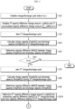
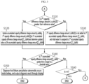
- FIGS. 2 to 5 are flowcharts for specifically illustrating a process of diagnosing a lithium precipitation abnormality while a control unit repeatedly performs a charge/discharge cycle according to an embodiment of the present disclosure.
- the control unit 18 may execute a battery abnormality diagnosing method according to an embodiment of the present disclosure according to the flowcharts shown in FIGS. 2 to 5 .
- control unit 18 starts the 1 st charge/discharge cycle for the battery 11 in Step S30.
- Step S40 the control unit 18 receives the current measurement value from the current measuring unit 14 during the 1 st charge/discharge cycle and calculates a charge capacity (ChgAh[1]) and discharge capacity (DchgAh[1]).
- the control unit 18 may control the charging device 13 to perform a charge cycle in a preset charging voltage section.
- the control unit 18 may perform a discharge cycle in a preset discharging voltage section by connecting the battery 11 to the load 12 after performing the charge cycle.
- the charging voltage section and the discharging voltage section may be the same or different.
- the discharge cycle starts after the voltage of the battery 11 is stabilized after the charge cycle is completed.
- the discharge cycle may end when the voltage of the battery 11 reaches a preset discharge end voltage or when the integrated value of the discharging current reaches a preset discharge capacity.
- the control unit 18 may refer to the voltage measurement value of the battery 11 measured through the voltage measuring unit 15. During the charge cycle and the discharge cycle, the control unit 18 may control the temperature adjusting unit 19 to keep the temperature of the battery 11 constant.
- temperature may be selected as an arbitrary value within the operating temperature range of the battery 11.
- the control unit 18 may determine a capacity difference (dAh[1]) corresponding to the difference between the charge capacity (ChgAh[1]) and the discharge capacity (DchgAh[1]) and record the capacity difference in the storage unit 17 together with a time stamp.
- the capacity difference (dAh[1]) may be determined by subtracting the discharge capacity (DchgAh[1]) from the charge capacity (ChgAh[1]).
- n is a natural number preset as the total number of charge/discharge cycles that can be performed to diagnose a lithium precipitation abnormality.
- n may be 20.
- n may be a value greater than or smaller than 20.
- Step S60 If the judgment in Step S60 is YES, the control unit 18 terminates the abnormality diagnosis process of the battery 11. Meanwhile, if the judgment at Step S60 is NO, the control unit 18 transfers the process to S70.
- Step S70 the control unit 18 starts the 2 th charge/discharge cycle.
- Conditions of the 2 th charge/discharge cycle are substantially the same as those of the 1 st charge/discharge cycle.
- control unit 18 determines a charge capacity (ChgAh[2]) and a discharge capacity (DchgAh[2]) during the 2 th charge/discharge cycle for the battery 11 in Step S80, and determines a capacity difference (dAh[2]) corresponding to the difference between the charge capacity (ChgAh[2]) and the discharge capacity (DchgAh[2]) in Step S90.
- Step S100 the control unit 18 determines a 2 th capacity difference change amount ( ⁇ dAh[2]) by subtracting the capacity difference (dAh[2]) of the 2 th charge/discharge cycle from the capacity difference (dAh[1]) of the 1 st charge/discharge cycle in Step S100.
- Step S110 of FIG. 3 is performed.
- control unit 18 judges whether the 2 th capacity difference change amount ( ⁇ dAh[2]) is greater than a reference value in Step S110.
- the reference value may be 0, but the present disclosure is not limited thereto.
- the threshold value may be set to a value suitable for diagnosing a lithium precipitation abnormality. In one example, the threshold value may be set to 0.1% of the capacity of the battery 11, but the present disclosure is not limited thereto.
- Step S140 the control unit 18 may diagnose that a lithium precipitation abnormality occurs inside the battery 11, and output the diagnosis result through the display 20.
- the diagnosis result includes a warning message indicating that a lithium precipitation abnormality occurs.
- the control unit 18 may end the diagnosis process after outputting the diagnosis result including a warning message through the display 20 in Step S150.
- Step S140 judges whether the index k for the charge/discharge cycle is identical to n in Step S160.
- n is the total number of charge/discharge cycles that can be performed to diagnose a lithium precipitation abnormality.
- Step S160 If the judgment in Step S160 is YES, since the charge/discharge cycles for diagnosing lithium precipitation are completely performed, it is finally diagnosed that no lithium precipitation abnormality occurs inside the battery 11, and the process is terminated.
- the control unit 18 may output the final diagnosis result through the display 20.
- the final diagnosis result may include a message indicating that no lithium precipitation abnormality occurs.
- Step S160 if the judgment in Step S160 is NO, the control unit 18 may further perform a charge/discharge cycle to diagnose a lithium precipitation abnormality. After Step S160, Step S180 of FIG. 4 is performed.
- Step S180 the control unit 18 starts the 3 th charge/discharge cycle.
- Conditions of the 3 th charge/discharge cycle are substantially the same as those of the 1 st charge/discharge cycle.
- control unit 18 determines a charge capacity (ChgAh[3]) and a discharge capacity (DchgAh[3]) during the 3 th charge/discharge cycle for the battery 11 in Step S190, and determines a capacity difference (dAh[3]) corresponding to the difference between the charge capacity (ChgAh[3]) and the discharge capacity (DchgAh[3]) in Step S200.
- control unit 18 determines a 3 th capacity difference change amount ( ⁇ dAh[3]) by subtracting the capacity difference (dAh[3]) of the 3 th charge/discharge cycle from the capacity difference (dAh[2]) of the 2 th charge/discharge cycle in Step S210.
- control unit 18 judges whether the 3 th capacity difference change amount ( ⁇ dAh[3]) is greater than the reference value in Step S220.
- the reference value may be 0, but the present disclosure is not limited thereto.
- Step S250 is performed.
- Step S260 the control unit 18 may diagnose that a lithium precipitation abnormality occurs inside the battery 11, and output the diagnosis result through the display 20.
- the diagnosis result includes a warning message indicating that a lithium precipitation abnormality occurs.
- the control unit 18 may end the diagnosis process after outputting the diagnosis result including a warning message through the display 20 in Step S260.
- Step S250 judges whether the index k for the charge/discharge cycle is identical to n in Step S270.
- n is the total number of charge/discharge cycles that can be performed to diagnose whether lithium precipitation occurs inside the battery 11.
- Step S270 If the judgment in Step S270 is YES, since the charge/discharge cycles for diagnosing a lithium precipitation abnormality are completely performed, it is finally diagnosed that no lithium precipitation abnormality occurs inside the battery 11, and the process is terminated.
- the control unit 18 may output a final diagnosis result through the display 20.
- the final diagnosis result may include a message indicating that no lithium precipitation abnormality occurs.
- control unit 18 may further perform a charge/discharge cycle to diagnose a lithium precipitation abnormality.
- a diagnosis logic for diagnosing a lithium precipitation abnormality performed by the control unit 18 in a 4 th charge/discharge cycle and subsequent charge/discharge cycles is substantially the same as described above.
- Step S280 the control unit 18 starts a k th (k is a natural number of 4 to n) charge/discharge cycle. Conditions of the k th charge/discharge cycle are substantially the same as those of the 1 st charge/discharge cycle.
- control unit 18 determines a charge capacity (ChgAh[k]) and a discharge capacity (DchgAh[k]) during the k th charge/discharge cycle for the battery 11 in Step S290, and determines a capacity difference (dAh[k]) corresponding to the difference between the charge capacity (ChgAh[k]) and the discharge capacity (DchgAh[k]) in Step S300.
- Step S310 the control unit 18 determines a k th capacity difference change amount ( ⁇ dAh[k]) by subtracting the capacity difference (dAh[k]) of the k th charge/discharge cycle from a capacity difference (dAh[k-1]) of a k-1 th charge/discharge cycle.
- Step S320 the control unit 18 judges whether the k th capacity difference change amount ( ⁇ dAh[k]) is greater than a reference value.
- the reference value may be 0, but the present disclosure is not limited thereto.
- Step S350 is performed.
- Step S360 the control unit 18 may diagnose that a lithium precipitation abnormality occurs inside the battery 11, and output the diagnosis result through the display 20.
- the diagnosis result includes a warning message indicating that a lithium precipitation abnormality occurs.
- the control unit 18 may output the diagnosis result including a warning message through the display 20 and then terminate the diagnosis process.
- n is the total number of charge/discharge cycles that can be performed to diagnose whether lithium precipitation occurs inside the battery 11.
- Step S370 If the judgment in Step S370 is YES, since the charge/discharge cycles for diagnosing lithium precipitation are completely performed, it is finally diagnosed that no lithium precipitation abnormality occurs inside the battery 11, and the process is terminated.
- the control unit 18 may output the final diagnosis result through the display 20.
- the final diagnosis result may include a message indicating that no lithium precipitation abnormality occurs.
- Step S370 determines whether the control unit 18 has performed a charge/discharge cycle. If the judgment in Step S370 is NO, the control unit 18 increases the index k of the charge/discharge cycle by 1 to further perform a charge/discharge cycle in order to diagnose a lithium precipitation abnormality, and then returns the process to S280. Thus, Steps S280 to S370 are periodically repeated until the index k of the charge/discharge cycle becomes n.
- the accumulated capacity difference change amount calculated until the previous cycle is initialized to 0.
- the present capacity difference change amount is added to the previous accumulated capacity difference change amount.
- the previous accumulated capacity difference change amount has 0 or a positive value. If the accumulated capacity difference change amount has a positive value, capacity difference change amounts greater than the reference value calculated in consecutive charge/discharge cycles are accumulated.
- the accumulated capacity difference change amount may be regarded as a kind of quantitative index that measures a lithium precipitation abnormality. That is, if the capacity difference change amount is greater than the reference value, it means that there is a possibility of lithium precipitation.
- the accumulated capacity difference change amount increases to the threshold value or above while continuously satisfying the condition in which the capacity difference change amount exceeds the reference value in a plurality of time-sequentially consecutive charge/discharge cycles, this means that the possibility of lithium precipitation is high as much.
- the present disclosure has technical significance in that the possibility of lithium precipitation is quantified using a factor, called an accumulated capacity difference change amount.
- FIG. 6 is a graph showing the change in data measured in an experimental example to which a battery abnormality diagnosing method according to an embodiment of the present disclosure is applied.
- a pouch-type lithium polymer battery is used.
- the lithium polymer battery selected for the experiment is deteriorated and in a state where lithium starts to precipitate on the negative electrode.
- the present capacity of the lithium polymer battery which reflects the degree of deterioration, is approximately 50 Ah.
- the charging condition of the charge cycle is CC (constant current)-CV (constant voltage) charging. When a CC charging target voltage is reached, the CC charging is terminated and converted into CV charging. When the CV charging current reaches a target current, the charging is terminated.
- the discharging condition of the discharge cycle is CC discharging, and the discharging is terminated when the discharging is performed as much as a given discharge capacity.
- the temperature condition of the charge cycle and the discharge cycle is 45°C.
- the reference value, which is the criterion for determining whether or not to integrate the capacity difference change amount, is 0, and the threshold value, which is the criterion for a diagnosing lithium precipitation abnormality, is set to 0.06 Ah.
- a sense resistor is used as the current measuring unit 14.
- the analog voltage measured at both ends of the sense resistor is input to the I/O interface of the control unit 18.
- the control unit 18 includes a circuit that amplifies a voltage signal input through the I/O interface and converts the amplified analog signal into a digital signal.
- the current value measured through this circuit has a difference (offset) from the actual current value.
- the discharge current measurement value has a larger error than the actual value. Accordingly, the discharge capacity may be greater than the charge capacity according to the index of the charge/discharge cycle.
- Graph 1 is a graph showing the measurement results of the charge capacity (ChgAh[k]) and the discharge capacity (DChgAh[k]) for each charge/discharge cycle.
- the charge capacity (ChgAh[k]) and the discharge capacity (DChgAh[k]) are calculated by integrating the current values measured through the sense resistor. Due to an error of the discharge current measurement value, the discharge capacity is greater than the charge capacity from the 4 th discharge cycle.
- Graph 2 is a graph showing the capacity difference (dAh[k]) for each charge/discharge cycle. Seeing Graph 1, since the discharge capacity is greater than the charge capacity from the 4 th charge/discharge cycle, the capacity difference (dAh[k]) becomes a negative value from the 4 th cycle.
- Graph 3 is a graph showing a capacity difference change amount ( ⁇ dAh[k]) for each charge/discharge cycle.
- the indices of charge/discharge cycles in which the capacity difference change amount ( ⁇ dAh[k]) is a positive number are 2 to 13, 17 to 18, and 20.
- the indices of charge/discharge cycles in which the capacity difference change amount ( ⁇ dAh[k]) is a negative number are 14 to 16 and 19.
- the control unit 18 diagnoses that a lithium precipitation abnormality occurs inside the battery, outputs the diagnosis result through the display 20, and terminates the diagnosis process. Since lithium is precipitated on the negative electrode of the lithium polymer battery used in this experiment, it may be found that the diagnostic accuracy of the present disclosure is high.
- FIG. 7 is a graph showing the change in data measured in another experimental example to which the battery abnormality diagnosing method according to an embodiment of the present disclosure is applied.
- Graph 1 is the same as Graph 1 of the experimental example described above.
- Graph 1' is a graph showing the measurement results of the charge capacity (ChgAh[k]) and the discharge capacity (DchgAh[k]) when a current measuring unit having a current measurement value error different from that of the experimental example described above is used.
- the error of the discharge current measurement value is larger than that of the experimental example described above. Therefore, the graph of the discharge capacity (DchgAh[k]) is shifted upward compared to the experimental example described above.
- Graphs (2) and (2)' are graphs showing a capacity difference (dAh[k]) for each charge/discharge cycle
- Graphs 3 and 3' are graphs showing a capacity difference change amount ( ⁇ dAh[k]) for each charge/discharge cycle
- Graphs (2), 3 and 4 are calculated using the data of Graph 1, and Graphs 2', 3' and 4' are calculated using the data of Graph 1'.
- Graphs (2), 3, and 4 and Graphs (2)', 3', and 4' are substantially the same. Therefore, even if the discharge current value has a measurement error, the control unit 18 performs the 13 th charge/discharge cycle regardless of the magnitude of the error, then diagnoses that a lithium precipitation abnormality occurs inside the battery, outputs the diagnosis result through the display 20, and terminates the diagnosis process. From these experimental results, it may be found that the present disclosure can reliably diagnose a lithium precipitation abnormality regardless of the error of the current measurement value.
- the battery abnormality diagnosing apparatus 10 may be included in a diagnosing system for diagnosing whether the battery 11 is abnormal.
- the diagnosing system may be operated by an electric vehicle maintenance shop, a battery manufacturer, or a battery maintenance company.
- the diagnosing system may be used for diagnosing abnormality of a battery installed in an electric vehicle or an energy storage system, or for diagnosing abnormality of a battery of a newly developed model produced by a battery manufacturer.
- the battery abnormality diagnosing apparatus 10 can be used to examine whether the battery contains a structural weakness that causes lithium precipitation.
- the battery abnormality diagnosing apparatus 10 may be included in a control element of a system in which the battery 11 is installed.
- the battery abnormality diagnosing apparatus 10 may be included in a control system of an electric vehicle.
- the battery abnormality diagnosing apparatus 10 may collect data on the charge capacity and discharge capacity of the battery in the process of charging and discharging the battery mounted in the electric vehicle, diagnose a lithium precipitation abnormality using the collected data, and output the diagnosis result to an integrated control display of the electric vehicle.
- the electric vehicle refers to a vehicle driven by a motor, such as an electric vehicle, a hybrid electric vehicle, or a plug-in hybrid vehicle.
- the vehicle may be two-wheeled, three-wheeled or four-wheeled.
- the battery abnormality diagnosing apparatus 10 may be included in a control system of an energy storage system.
- the battery abnormality diagnosing apparatus 10 may collect data on the charge capacity and discharge capacity of the battery in the process of charging and discharging the energy storage system, diagnose a lithium precipitation abnormality using the collected data, and output the diagnosis result through a display of an integrated management computer accessible by an operator.
- Users of electric vehicles or operators of energy storage systems may take appropriate safety measures when the diagnosis result of lithium precipitation abnormality is output through the display.
- a user of an electric vehicle may visit a maintenance shop and receive an inspection.
- an operator of an energy storage system may replace a corresponding battery with a new battery.
- control unit 18 may be a control circuit.
- the control unit 18 may optionally include a processor, an application-specific integrated circuit (ASIC), other chipsets, logic circuits, registers, communication modems, data processing devices, etc. known in the art to execute the various control logics described above.
- ASIC application-specific integrated circuit
- the control unit 18 may be implemented as a set of program modules.
- the program module may be stored in a memory and executed by the processor.
- the memory may be provided inside or outside the processor, and may be connected to the processor by various well-known computer components.
- the memory may be included in the storage unit 17 of the present disclosure.
- the memory generically refers to a device that stores information regardless of the type of device, and does not refer to a specific memory device.
- One or more of the various control logics of the control unit 18 are combined, and the combined control logics may be written in a computer-readable code system and recorded on a computer-readable recording medium.
- the type of the recording medium is not particularly limited as long as it can be accessed by a processor included in a computer.
- the recording medium includes at least one selected from the group including a ROM, a RAM, a register, a CD-ROM, a magnetic tape, a hard disk, a floppy disk, and an optical data recording device.
- the code system may be distributed and stored and executed in computers connected through a network.
- functional programs, codes and code segments for implementing the combined control logics may be easily inferred by programmers in the art to which the present disclosure belongs.
- each component may be selectively integrated with other components or each component may be divided into sub-components for efficient execution of control logic(s).
- control logic control logic
Landscapes
- Engineering & Computer Science (AREA)
- Manufacturing & Machinery (AREA)
- Chemical & Material Sciences (AREA)
- Chemical Kinetics & Catalysis (AREA)
- Electrochemistry (AREA)
- General Chemical & Material Sciences (AREA)
- Physics & Mathematics (AREA)
- General Physics & Mathematics (AREA)
- Power Engineering (AREA)
- Secondary Cells (AREA)
- Charge And Discharge Circuits For Batteries Or The Like (AREA)
Abstract
Description
- The present disclosure relates to a battery abnormality diagnosing apparatus and method, and more particularly, to a battery abnormality diagnosing apparatus and method capable of accurately diagnosing whether a battery is abnormal regardless of an error of a current sensor by time-sequentially analyzing the difference between a charge capacity and a discharge capacity.
- The present application claims priority to
Korean Patent Application No. 10-2021-0166209 filed on November 26, 2021 Korean Patent Application No. 10-2022-0157731 filed on November 22, 2022 - Batteries used in electric vehicles or energy storage systems (ESS) may ignite in use. One of the most likely causes of ignition is lithium precipitation on the surface of the negative electrode.
- In the case of a normal battery, lithium ions emitting from the positive electrode must diffuse into the negative electrode during charging. However, in the case of a defective battery, some lithium ions are precipitated in the form of lithium metal on the surface of the negative electrode. Precipitated lithium continues to grow in the form of dendrite in the repetitive charging process.
- Lithium precipitated on the surface of the negative electrode comes into contact with an adjacent positive electrode current collecting plate or an adjacent negative electrode current collecting plate, causing an internal short circuit. The internal short circuit rapidly raises the temperature inside the battery and, in serious cases, even causes a fire accident.
- Therefore, battery manufacturers are actively conducting research and development on technology for diagnosing lithium precipitation.
- One of the prior art for diagnosing lithium precipitation is based on analyzing the change pattern of voltage when the battery enters a rest mode after being charged. When the battery enters the rest mode after being charged, the polarization of the electrode surface is relieved and the voltage is gradually lowered to reach an equilibrium state. However, if lithium precipitation occurs in the charge cycle, when the battery enters the rest mode, the lithium precipitated on the surface of the negative electrode diffuses into the negative electrode, and fine charging continues. Therefore, the voltage profile of the battery where lithium precipitation occurs includes an inflection point, and lithium precipitation can be diagnosed by detecting the appearance of the inflection point. However, in this diagnostic technology, the inflection point can be detected only when a large amount of lithium precipitation occurs in the charge cycle. That is, when the amount of lithium precipitation is not large, it is not easy to diagnose lithium precipitation.
- Meanwhile, when the battery is discharged, lithium comes out from the negative electrode and is inserted into the positive electrode again. However, the lithium precipitated on the surface of the negative electrode cannot participate in such a reaction, so the discharge capacity of the battery with lithium precipitation is smaller than the charge capacity. Therefore, by analyzing the difference between charge capacity and the discharge capacity, it is possible to diagnose lithium precipitation. However, it is difficult to trust the diagnosis result if the charge capacity and the discharge capacity show an error from the actual true value due to an error of the current sensor. For reference, when a sense resistor is used as a current sensor, an error occurs in the process of amplifying the voltage applied to both ends of the sense resistor and converting the amplified voltage from analog signal to digital data. Even if the magnitudes of the charging current and discharging current are the same, the actual measured value may show a difference depending on the offset of the current sensor. Therefore, there is also a limit to diagnosing lithium precipitation only with the difference between the charge capacity and the discharge capacity.
- The present disclosure is designed to solve the problems of the related art, and therefore the present disclosure is directed to providing a battery abnormality diagnosing apparatus and method having robustness to an error of a current sensor in diagnosing lithium precipitation based on the difference between a charge capacity and a discharge capacity.
- In addition, the present disclosure is directed to providing a system or an electric vehicle including the battery abnormality diagnosing apparatus.
- In one aspect of the present disclosure, there is provided a battery abnormality diagnosing apparatus, comprising: a current measuring unit configured to measure a charging current or a discharging current of a battery; and a control unit operably coupled with the current measuring unit and configured to diagnose a lithium precipitation abnormality while performing a plurality of charge/discharge cycles for the battery.
- Preferably, the control unit may be configured to receive a current measurement value from the current measuring unit in a kth (k is a natural number greater than or equal to 2) charge/discharge cycle to calculate a charge capacity (ChgAh[k]) and a discharge capacity (DchgAh[k]), determine a capacity difference (dAh[k]) corresponding to a difference between the charge capacity (ChgAh[k]) and the discharge capacity (DchgAh[k]), determine a kth capacity difference change amount (△dAh[k]) by subtracting the capacity difference (dAh[k]) of the kth charge/discharge cycle from a capacity difference (dAh[k-1]) of a k-1th charge/discharge cycle, update an accumulated capacity difference change amount by adding the kth capacity difference change amount (△dAh[k]) to the accumulated capacity difference change amount, and diagnose that a lithium precipitation abnormality occurs when the updated accumulated capacity difference change amount is greater than or equal to a threshold value.
- Preferably, the control unit may be configured to update the accumulated capacity difference change amount by adding the kth capacity difference change amount (△dAh[k]) to the accumulated capacity difference change amount when the kth capacity difference change amount (△dAh[k]) is greater than a reference value.
- Preferably, the control unit may be configured to update the accumulated capacity difference change amount by adding the kth capacity difference change amount (△dAh[k]) to the accumulated capacity difference change amount when both the k-1th capacity difference change amount (△dAh[k-1]) and the kth capacity difference change amount (△dAh[k]) are greater than a reference value.
- Preferably, the control unit may be configured to assign an initial value of 0 to the accumulated capacity difference change amount when the kth capacity difference change amount (△dAh[k]) is less than or equal to a reference value.
- Preferably, the reference value may be 0.
- In an embodiment, when performing each charge/discharge cycle, the control unit may be configured to perform the charge cycles in the same charging voltage section and perform the discharge cycles in the same discharging voltage section.
- In another embodiment, when performing each charge/discharge cycle, the control unit may be configured to perform the charge cycles in the same charging voltage section and perform the discharge cycles in the same discharge capacity condition.
- Preferably, the battery abnormality diagnosing apparatus according to the present disclosure may further comprise a display coupled to the control unit, and the control unit may be configured to diagnose that a lithium precipitation abnormality occurs when the accumulated capacity difference change amount is greater than or equal to the threshold value and output a diagnosis result through the display.
- In another aspect of the present disclosure, there is provided a battery abnormality diagnosing method, comprising: (a) receiving a current measurement value from a current measuring unit in a kth (k is a natural number greater than or equal to 2) charge/discharge cycle to calculate a charge capacity and a discharge capacity; (b) determining a capacity difference corresponding to a difference between the charge capacity and the discharge capacity; (c) determining a kth capacity difference change amount by subtracting the capacity difference of the kth charge/discharge cycle from a capacity difference of a k-1th charge/discharge cycle; (d) updating an accumulated capacity difference change amount by adding the kth capacity difference change amount to the accumulated capacity difference change amount; and (e) diagnosing that a lithium precipitation abnormality occurs when the updated accumulated capacity difference change amount is greater than or equal to a threshold value.
- In another aspect of the present disclosure, there is provided a system and an electric vehicle, comprising the battery abnormality diagnosing apparatus.
- According to an embodiment of the present disclosure, it is possible to reliably diagnose whether the battery is abnormal by quantifying the possibility of lithium precipitation inside the battery using a factor that is called an accumulated capacity difference change amount, which is not affected by a current measurement error.
- According to another embodiment of the present disclosure, even if measurement values for a charging current and a discharging current have errors from actual values, it is possible to reliably diagnose whether the battery is abnormal.
- According to still another embodiment of the present disclosure, even if the measurement error of the charging current and the measurement error of the discharging current are different, it is possible to reliably diagnose whether the battery is abnormal.
- According to still another embodiment of the present disclosure, the accumulated capacity difference change amount is calculated by integrating the capacity difference change amount only when the condition in which the capacity difference change amount calculated in each charge/discharge cycle exceeds a reference value is continuously satisfied, and when an event in which the capacity difference change amount does not exceed the reference value occurs, the accumulated capacity difference change amount is reset to 0, thereby minimizing the noise effect.
- According to still another embodiment of the present disclosure, various systems and electric vehicles including the battery abnormality diagnosing apparatus may be provided.
- The accompanying drawings illustrate a preferred embodiment of the present disclosure and together with the foregoing disclosure, serve to provide further understanding of the technical features of the present disclosure, and thus, the present disclosure is not construed as being limited to the drawing.
-
FIG. 1 is a block diagram showing a schematic configuration of a batteryabnormality diagnosing apparatus 10 according to an embodiment of the present disclosure. -
FIGS. 2 to 5 are flowcharts for specifically illustrating a process of diagnosing a lithium precipitation abnormality while a control unit repeatedly performs a charge/discharge cycle according to an embodiment of the present disclosure. -
FIG. 6 is a graph showing the change in data measured in an experimental example to which a battery abnormality diagnosing method according to an embodiment of the present disclosure is applied. -
FIG. 7 is a graph showing the change in data measured in another experimental example to which the battery abnormality diagnosing method according to an embodiment of the present disclosure is applied. - Hereinafter, preferred embodiments of the present disclosure will be described in detail with reference to the accompanying drawings. Prior to the description, it should be understood that the terms used in the specification and the appended claims should not be construed as limited to general and dictionary meanings, but interpreted based on the meanings and concepts corresponding to technical aspects of the present disclosure on the basis of the principle that the inventor is allowed to define terms appropriately for the best explanation. Therefore, the description proposed herein is just a preferable example for the purpose of illustrations only, not intended to limit the scope of the disclosure, so it should be understood that other equivalents and modifications could be made thereto without departing from the scope of the disclosure.
-
FIG. 1 is a block diagram showing a schematic configuration of a batteryabnormality diagnosing apparatus 10 according to an embodiment of the present disclosure. - Referring to
FIG. 1 , the batteryabnormality diagnosing apparatus 10 may diagnose lithium precipitation of abattery 11 while performing the charge/discharge cycle of thebattery 11 multiple times. - The battery
abnormality diagnosing apparatus 10 may be a dedicated device for diagnosing thebattery 11. When thebattery 11 is mounted in an electric vehicle, the batteryabnormality diagnosing apparatus 10 may be included in a diagnosing system provided in a maintenance shop of the electric vehicle. A user of an electric vehicle may visit a maintenance shop regularly and receive a battery abnormality diagnosis service. At this time, the batteryabnormality diagnosing apparatus 10 of the diagnosing system may be connected to thebattery 11 of the electric vehicle to diagnose the abnormality of thebattery 11. Preferably, the abnormality diagnosis is lithium precipitation on the surface of a negative electrode of thebattery 11. - Alternatively, the battery
abnormality diagnosing apparatus 10 may be included in control elements of various systems in which thebattery 11 is installed. In one example, when thebattery 11 is included in an energy storage system, theabnormality diagnosing apparatus 10 may be included in a control element (e.g., an ESS control system) of the energy storage system. In another example, when thebattery 11 is included in an electric vehicle, theabnormality diagnosing apparatus 10 may be included in a control element (e.g., a vehicle control system) of the electric vehicle. - In an embodiment of the present disclosure, the charge/discharge cycle includes a charge cycle and a discharge cycle.
- In one example, the charge cycle means to charge the battery from a lower limit to an upper limit of a preset charging voltage section while maintaining the temperature of the
battery 11 constant and then stop charging. The discharge cycle means that after the charge cycle is completed, thebattery 11 is stabilized for a predetermined time, the battery is discharged from an upper limit to a lower limit of a preset discharging voltage section while maintaining the temperature of thebattery 11 in the same way as the charge cycle, and then the discharge is stopped. The charging voltage section and the discharging voltage section may be the same or different. However, in performing a plurality of charge/discharge cycles, it is preferable that charging voltage sections between charge cycles are the same and discharging voltage sections between discharge cycles are also the same. - In another example, the charge cycle means to charge the battery from the lower limit to the upper limit of the preset charging voltage section while maintaining the temperature of the
battery 11 constant and then stop charging. The discharge cycle means that the discharge starts from the upper limit of the preset discharging voltage section, and by integrating the discharging current, the discharging is stopped when the current integration value reaches a preset discharge capacity. In performing a plurality of charge/discharge cycles, it is preferable that charging voltage sections between charge cycles are the same and discharge capacities between discharge cycles are the same. - The
battery 11 may be a lithium secondary battery, but the present disclosure is not limited by the type of battery. Therefore, any secondary battery that can be repeatedly charged and discharged may correspond to thebattery 11. Thebattery 11 includes at least one unit cell. The unit cell may be a pouch cell, a cylindrical cell or a prismatic cell. When there are a plurality of unit cells, the unit cells may be connected in series and/or in parallel. - In an embodiment of the present disclosure, it is assumed that the
battery 11 includes one unit cell or a plurality of unit cells connected in parallel. However, the present disclosure is not limited by the number of unit cells and the electrical connection relationship between unit cells. - When the
battery 11 includes a plurality of unit cells connected in series, it is obvious to those skilled in the art that the embodiment of the present disclosure can be applied to diagnose abnormality of each unit cell. - The
battery 11 may be connected to aload 12 for performing the discharge cycle. Theload 12 may include a discharge element such as a resistor. Alternatively, theload 12 consumes energy of thebattery 11 and may be a motor of an electric vehicle, an electric device connected to a power system, or a power conversion device such as an inverter or a converter. - The
battery 11 may be connected to acharging device 13 for performing the charge cycle. The chargingdevice 13 may be a dedicated charging device for diagnosing abnormality of thebattery 11. Alternatively, the chargingdevice 13 may be a charging station of an electric vehicle or a power converting system (PCS) of an energy storage system. The present disclosure is not limited by the type of theload 12 or the chargingdevice 13. - The battery
abnormality diagnosing apparatus 10 may include acurrent measuring unit 14 that measures current flowing through thebattery 11. The current may be a charging current or a discharging current. Thecurrent measuring unit 14 measures the current flowing through thebattery 11 at regular time intervals and outputs the current measurement value to thecontrol unit 16. Preferably, thecurrent measuring unit 14 may be installed on a line through which the charging current and the discharging current flow. - The
current measuring unit 14 may be a current measuring circuit. Thecurrent measuring unit 14 may include a hall sensor or a sense resistor that outputs a voltage value corresponding to the magnitude of current. The voltage value output from the hall sensor or the voltage value at both ends of the sense resistor may be converted into a current value according to Ohm's law. Conversion of a voltage value to a current value may be handled by acontrol unit 18. To this end, thecontrol unit 18 may include an I/O interface coupled with thecurrent measuring unit 14, an amplifier circuit that amplifies the voltage signal input through the I/O interface, and an analog-digital conversion circuit that digitizes the voltage signal output from the amplifier circuit. - The current measurement value measured using the
current measuring unit 14 may have an error with the actual value. In one example, when thecurrent measuring unit 14 is a sense resistor, the amplifier circuit that detects voltage at both ends of the sense resistor may have different gains depending on the direction of current flowing through the sense resistor. Therefore, when thecurrent measuring unit 14 is a sense resistor, the measurement values may be different even if the magnitudes of the charging current and discharging current are the same. - The battery
abnormality diagnosing apparatus 10 may include avoltage measuring unit 15 that measures the voltage of thebattery 11. Thevoltage measuring unit 15 measures the voltage of thebattery 11 at regular time intervals while thebattery 11 is being charged or discharged, and outputs the voltage measurement value to thecontrol unit 18. Thevoltage measuring unit 15 may be a voltage measuring circuit known in the art. Since the voltage measurement circuit is widely known, it will not be described in detail. - The battery
abnormality diagnosing apparatus 10 may include atemperature measuring unit 16. Thetemperature measuring unit 16 measures the temperature of thebattery 11 at regular time intervals while thebattery 11 is being charged or discharged, and outputs the temperature measurement value to thecontrol unit 18. Thetemperature measuring unit 16 may be a temperature measuring circuit. Thetemperature measuring unit 16 may include a thermocouple or a temperature measuring element that outputs a voltage value corresponding to temperature. The voltage value may be converted into a temperature value by using a voltage-temperature conversion look-up table (function). Conversion of voltage value to temperature value may be handled by thecontrol unit 18. - The battery
abnormality diagnosing apparatus 10 may include astorage unit 17. The type ofstorage unit 17 is not particularly limited as long as it can record and erase data and/or information. As an example, thestorage unit 17 may be a RAM, a ROM, a register, a flash memory, a hard disk, or a magnetic recording medium. - The
storage unit 17 may be electrically connected to thecontrol unit 18 via, for example, a data bus to allow access by thecontrol unit 18. - The
storage unit 17 stores and/or updates and/or erase and/or transmit programs including various control logics executed by thecontrol unit 18, and/or data generated when control logics are executed, and/or preset data, parameters, lookup information/tables, etc. - Preferably, the
control unit 18 is operably coupled to thecurrent measuring unit 14, thevoltage measuring unit 15, thetemperature measuring unit 16 and thestorage unit 17. - The
control unit 18 may perform charge/discharge cycles multiple times while constantly maintaining the temperature of thebattery 18 at a set temperature in order to diagnose abnormality of thebattery 11. Thecontrol unit 18 may connect the chargingdevice 13 with thebattery 11 when performing the charge cycle, and may connect theload 12 with thebattery 11 when performing the discharge cycle. - The
control unit 18 may be operably coupled with thetemperature adjusting unit 19 to keep the temperature of thebattery 11 constant. Thetemperature adjusting unit 19 may include an electric heater or a fluid circulation loop. Thecontrol unit 18 may maintain the temperature of thebattery 11 at the set temperature by controlling thetemperature adjusting unit 19. In one example, thecontrol unit 18 may maintain the temperature of thebattery 11 constant at the set temperature by adjusting the power of the electric heater or adjusting the temperature of the fluid supplied to the fluid circulation loop. Thetemperature adjusting unit 19 may be coupled with thebattery 11 to come into contact with the surface of thebattery 11. - During the charge/discharge cycle, the
control unit 18 may periodically measure the amount of current flowing through thebattery 11 using thecurrent measuring unit 14 and record the current measurement value in thestorage unit 17 along with a time stamp. - The
control unit 18 may also periodically measure the voltage of thebattery 11 through thevoltage measuring unit 15 during the charge/discharge cycle and record the voltage measurement value in thestorage unit 17 together with a time stamp. - The
control unit 18 may also periodically measure the temperature of thebattery 11 through thetemperature measuring unit 16 during the charge/discharge cycle and record the temperature measurement value in thestorage unit 17 together with a time stamp. - Preferably, the
control unit 18 may diagnose a lithium precipitation abnormality while performing a plurality of charge/discharge cycles for thebattery 11. The number of charge/discharge cycles to diagnose a lithium precipitation abnormality may be preset. In one example, the number of charge/discharge cycles may be 20. -
FIGS. 2 to 5 are flowcharts for specifically illustrating a process of diagnosing a lithium precipitation abnormality while a control unit repeatedly performs a charge/discharge cycle according to an embodiment of the present disclosure. - The
control unit 18 may execute a battery abnormality diagnosing method according to an embodiment of the present disclosure according to the flowcharts shown inFIGS. 2 to 5 . - First, the
control unit 18 initializes the charge/discharge cycle index k to 1 in Step 510, and initializes a 1st capacity difference change amount ΔdAh[1] and a 1st accumulated capacity difference change amount (
- Subsequently, the
control unit 18 starts the 1st charge/discharge cycle for thebattery 11 in Step S30. - Subsequently, in Step S40, the
control unit 18 receives the current measurement value from thecurrent measuring unit 14 during the 1st charge/discharge cycle and calculates a charge capacity (ChgAh[1]) and discharge capacity (DchgAh[1]). - In step S40, the
control unit 18 may control the chargingdevice 13 to perform a charge cycle in a preset charging voltage section. In addition, thecontrol unit 18 may perform a discharge cycle in a preset discharging voltage section by connecting thebattery 11 to theload 12 after performing the charge cycle. The charging voltage section and the discharging voltage section may be the same or different. Preferably, the discharge cycle starts after the voltage of thebattery 11 is stabilized after the charge cycle is completed. In addition, the discharge cycle may end when the voltage of thebattery 11 reaches a preset discharge end voltage or when the integrated value of the discharging current reaches a preset discharge capacity. When the start and end of the charge cycle and the discharge cycle are controlled based on the voltage value, thecontrol unit 18 may refer to the voltage measurement value of thebattery 11 measured through thevoltage measuring unit 15. During the charge cycle and the discharge cycle, thecontrol unit 18 may control thetemperature adjusting unit 19 to keep the temperature of thebattery 11 constant. Here, temperature may be selected as an arbitrary value within the operating temperature range of thebattery 11. - In step S50, the
control unit 18 may determine a capacity difference (dAh[1]) corresponding to the difference between the charge capacity (ChgAh[1]) and the discharge capacity (DchgAh[1]) and record the capacity difference in thestorage unit 17 together with a time stamp. In one example, the capacity difference (dAh[1]) may be determined by subtracting the discharge capacity (DchgAh[1]) from the charge capacity (ChgAh[1]). - Then, at Step S60, the
control unit 18 judges whether the index k for the charge/discharge cycle is equal to n. n is a natural number preset as the total number of charge/discharge cycles that can be performed to diagnose a lithium precipitation abnormality. In one example, n may be 20. In another example, n may be a value greater than or smaller than 20. - If the judgment in Step S60 is YES, the
control unit 18 terminates the abnormality diagnosis process of thebattery 11. Meanwhile, if the judgment at Step S60 is NO, thecontrol unit 18 transfers the process to S70. - In Step S70, the
control unit 18 starts the 2th charge/discharge cycle. Conditions of the 2th charge/discharge cycle are substantially the same as those of the 1st charge/discharge cycle. - Subsequently, the
control unit 18 determines a charge capacity (ChgAh[2]) and a discharge capacity (DchgAh[2]) during the 2th charge/discharge cycle for thebattery 11 in Step S80, and determines a capacity difference (dAh[2]) corresponding to the difference between the charge capacity (ChgAh[2]) and the discharge capacity (DchgAh[2]) in Step S90. - Then, the
control unit 18 determines a 2th capacity difference change amount (△dAh[2]) by subtracting the capacity difference (dAh[2]) of the 2th charge/discharge cycle from the capacity difference (dAh[1]) of the 1st charge/discharge cycle in Step S100. After Step S100, Step S110 ofFIG. 3 is performed. - Subsequently, the
control unit 18 judges whether the 2th capacity difference change amount (△dAh[2]) is greater than a reference value in Step S110. Preferably, the reference value may be 0, but the present disclosure is not limited thereto. - If the judgment in Step S110 is YES, in Step S120, the
control unit 18 updates an accumulated capacity difference change amount by adding the 2th capacity difference change amount (△dAh[2]) to the 1st accumulated capacity difference change amount (


- Meanwhile, if the judgment in Step S110 is NO, the 2th capacity difference change amount (ΔdAh[2]) is not added to the 1st accumulated capacity difference change amount (

initial value 0 is assigned to the 2th accumulated capacity difference change amount (
- Subsequently, the
control unit 18 judges whether the 2th accumulated capacity difference change amount (
battery 11, but the present disclosure is not limited thereto. - If the judgment in Step S140 is YES, the
control unit 18 may diagnose that a lithium precipitation abnormality occurs inside thebattery 11, and output the diagnosis result through thedisplay 20. Preferably, the diagnosis result includes a warning message indicating that a lithium precipitation abnormality occurs. Thecontrol unit 18 may end the diagnosis process after outputting the diagnosis result including a warning message through thedisplay 20 in Step S150. - If the judgment in Step S140 is NO, that is, if the 2th accumulated capacity difference change amount (

control unit 18 judges whether the index k for the charge/discharge cycle is identical to n in Step S160. Here, n is the total number of charge/discharge cycles that can be performed to diagnose a lithium precipitation abnormality. - If the judgment in Step S160 is YES, since the charge/discharge cycles for diagnosing lithium precipitation are completely performed, it is finally diagnosed that no lithium precipitation abnormality occurs inside the
battery 11, and the process is terminated. Thecontrol unit 18 may output the final diagnosis result through thedisplay 20. The final diagnosis result may include a message indicating that no lithium precipitation abnormality occurs. - Meanwhile, if the judgment in Step S160 is NO, the
control unit 18 may further perform a charge/discharge cycle to diagnose a lithium precipitation abnormality. After Step S160, Step S180 ofFIG. 4 is performed. - That is, in Step S180, the
control unit 18 starts the 3th charge/discharge cycle. Conditions of the 3th charge/discharge cycle are substantially the same as those of the 1st charge/discharge cycle. - Subsequently, the
control unit 18 determines a charge capacity (ChgAh[3]) and a discharge capacity (DchgAh[3]) during the 3th charge/discharge cycle for thebattery 11 in Step S190, and determines a capacity difference (dAh[3]) corresponding to the difference between the charge capacity (ChgAh[3]) and the discharge capacity (DchgAh[3]) in Step S200. - Subsequently, the
control unit 18 determines a 3th capacity difference change amount (△dAh[3]) by subtracting the capacity difference (dAh[3]) of the 3th charge/discharge cycle from the capacity difference (dAh[2]) of the 2th charge/discharge cycle in Step S210. - Subsequently, the
control unit 18 judges whether the 3th capacity difference change amount (△dAh[3]) is greater than the reference value in Step S220. Preferably, the reference value may be 0, but the present disclosure is not limited thereto. - If the judgment in Step S220 is YES, in Step S230, the
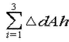
control unit 18 updates an accumulated capacity difference change amount by adding the 3th capacity difference change amount (△dAh[3]) to the 2th accumulated capacity difference change amount (
- Meanwhile, if the judgment in Step S220 is NO, in Step S240, the
control unit 18 does not add the 3th capacity difference change amount (ΔdAh[3]) to the 2th accumulated capacity difference change amount (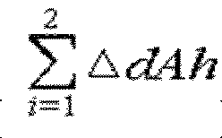
initial value 0 to the 3th accumulated capacity difference change amount (
- After Step S230 and Step S240, Step S250 is performed.
- In Step S250, the
control unit 18 judges whether the 3th accumulated capacity difference change amount (
- If the judgment in Step S250 is YES, in Step S260, the
control unit 18 may diagnose that a lithium precipitation abnormality occurs inside thebattery 11, and output the diagnosis result through thedisplay 20. Preferably, the diagnosis result includes a warning message indicating that a lithium precipitation abnormality occurs. Thecontrol unit 18 may end the diagnosis process after outputting the diagnosis result including a warning message through thedisplay 20 in Step S260. - If the judgment in Step S250 is NO, that is, if the 3th accumulated capacity difference change amount (

control unit 18 judges whether the index k for the charge/discharge cycle is identical to n in Step S270. Here, n is the total number of charge/discharge cycles that can be performed to diagnose whether lithium precipitation occurs inside thebattery 11. - If the judgment in Step S270 is YES, since the charge/discharge cycles for diagnosing a lithium precipitation abnormality are completely performed, it is finally diagnosed that no lithium precipitation abnormality occurs inside the
battery 11, and the process is terminated. Thecontrol unit 18 may output a final diagnosis result through thedisplay 20. The final diagnosis result may include a message indicating that no lithium precipitation abnormality occurs. - Meanwhile, if the judgment in Step S270 is NO, the
control unit 18 may further perform a charge/discharge cycle to diagnose a lithium precipitation abnormality. - A diagnosis logic for diagnosing a lithium precipitation abnormality performed by the
control unit 18 in a 4th charge/discharge cycle and subsequent charge/discharge cycles is substantially the same as described above. - Hereinafter, a process performed by the
control unit 18 in the 4th to nth charge/discharge cycles will be generalized and described with reference toFIG. 5 . - In Step S280, the
control unit 18 starts a kth (k is a natural number of 4 to n) charge/discharge cycle. Conditions of the kth charge/discharge cycle are substantially the same as those of the 1st charge/discharge cycle. - Subsequently, the
control unit 18 determines a charge capacity (ChgAh[k]) and a discharge capacity (DchgAh[k]) during the kth charge/discharge cycle for thebattery 11 in Step S290, and determines a capacity difference (dAh[k]) corresponding to the difference between the charge capacity (ChgAh[k]) and the discharge capacity (DchgAh[k]) in Step S300. - Subsequently, in Step S310, the
control unit 18 determines a kth capacity difference change amount (△dAh[k]) by subtracting the capacity difference (dAh[k]) of the kth charge/discharge cycle from a capacity difference (dAh[k-1]) of a k-1th charge/discharge cycle. - Subsequently, in Step S320, the
control unit 18 judges whether the kth capacity difference change amount (△dAh[k]) is greater than a reference value. Preferably, the reference value may be 0, but the present disclosure is not limited thereto. - If the judgment in Step S320 is YES, in Step S330, the
control unit 18 updates the accumulated capacity difference change amount by adding the kth capacity difference change amount (△dAh[k]) to the k-1th accumulated capacity difference change amount (

- Meanwhile, if the judgment in Step S320 is NO, in Step S340, the
control unit 18 does not add the kth capacity difference change amount (ΔdAh[k]) to the k-1th accumulated capacity difference change amount (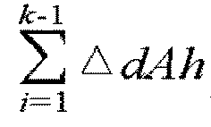

- After Step S330 and Step S340, Step S350 is performed.
- In Step S350, the
control unit 18 judges whether the kth accumulated capacity difference change amount (
- If the judgment in Step S350 is YES, in Step S360, the
control unit 18 may diagnose that a lithium precipitation abnormality occurs inside thebattery 11, and output the diagnosis result through thedisplay 20. Preferably, the diagnosis result includes a warning message indicating that a lithium precipitation abnormality occurs. In Step S360, thecontrol unit 18 may output the diagnosis result including a warning message through thedisplay 20 and then terminate the diagnosis process. - If the judgment in Step S350 is NO, that is, if the kth accumulated capacity difference change amount (

control unit 18 judges whether the index k for the charge/discharge cycle is identical to k in Step S370. Here, n is the total number of charge/discharge cycles that can be performed to diagnose whether lithium precipitation occurs inside thebattery 11. - If the judgment in Step S370 is YES, since the charge/discharge cycles for diagnosing lithium precipitation are completely performed, it is finally diagnosed that no lithium precipitation abnormality occurs inside the
battery 11, and the process is terminated. Thecontrol unit 18 may output the final diagnosis result through thedisplay 20. The final diagnosis result may include a message indicating that no lithium precipitation abnormality occurs. - Meanwhile, if the judgment in Step S370 is NO, the
control unit 18 increases the index k of the charge/discharge cycle by 1 to further perform a charge/discharge cycle in order to diagnose a lithium precipitation abnormality, and then returns the process to S280. Thus, Steps S280 to S370 are periodically repeated until the index k of the charge/discharge cycle becomes n. - According to an embodiment of the present disclosure, when the capacity difference change amount calculated in the present charge/discharge cycle is less than or equal to the reference value, the accumulated capacity difference change amount calculated until the previous cycle is initialized to 0. In addition, if the capacity difference change amount calculated in the present charge/discharge cycle is greater than the reference value, the present capacity difference change amount is added to the previous accumulated capacity difference change amount. As a result, the accumulated capacity difference change amount increases. The previous accumulated capacity difference change amount has 0 or a positive value. If the accumulated capacity difference change amount has a positive value, capacity difference change amounts greater than the reference value calculated in consecutive charge/discharge cycles are accumulated. In addition, while the capacity difference change amounts being accumulated, if the capacity difference change amount decreases to the reference value or below in a specific charge/discharge cycle, the accumulated capacity difference change amount is initialized to 0. By applying this logic, the accumulated capacity difference change amount may be regarded as a kind of quantitative index that measures a lithium precipitation abnormality. That is, if the capacity difference change amount is greater than the reference value, it means that there is a possibility of lithium precipitation. In addition, if the accumulated capacity difference change amount increases to the threshold value or above while continuously satisfying the condition in which the capacity difference change amount exceeds the reference value in a plurality of time-sequentially consecutive charge/discharge cycles, this means that the possibility of lithium precipitation is high as much. The present disclosure has technical significance in that the possibility of lithium precipitation is quantified using a factor, called an accumulated capacity difference change amount.
-
FIG. 6 is a graph showing the change in data measured in an experimental example to which a battery abnormality diagnosing method according to an embodiment of the present disclosure is applied. - In this experimental example, a pouch-type lithium polymer battery is used. The lithium polymer battery selected for the experiment is deteriorated and in a state where lithium starts to precipitate on the negative electrode. The present capacity of the lithium polymer battery, which reflects the degree of deterioration, is approximately 50 Ah. The charging condition of the charge cycle is CC (constant current)-CV (constant voltage) charging. When a CC charging target voltage is reached, the CC charging is terminated and converted into CV charging. When the CV charging current reaches a target current, the charging is terminated. The discharging condition of the discharge cycle is CC discharging, and the discharging is terminated when the discharging is performed as much as a given discharge capacity. The temperature condition of the charge cycle and the discharge cycle is 45°C. The reference value, which is the criterion for determining whether or not to integrate the capacity difference change amount, is 0, and the threshold value, which is the criterion for a diagnosing lithium precipitation abnormality, is set to 0.06 Ah.
- A sense resistor is used as the
current measuring unit 14. The analog voltage measured at both ends of the sense resistor is input to the I/O interface of thecontrol unit 18. Thecontrol unit 18 includes a circuit that amplifies a voltage signal input through the I/O interface and converts the amplified analog signal into a digital signal. The current value measured through this circuit has a difference (offset) from the actual current value. In this experimental example, the discharge current measurement value has a larger error than the actual value. Accordingly, the discharge capacity may be greater than the charge capacity according to the index of the charge/discharge cycle. -
Graph ① is a graph showing the measurement results of the charge capacity (ChgAh[k]) and the discharge capacity (DChgAh[k]) for each charge/discharge cycle. The charge capacity (ChgAh[k]) and the discharge capacity (DChgAh[k]) are calculated by integrating the current values measured through the sense resistor. Due to an error of the discharge current measurement value, the discharge capacity is greater than the charge capacity from the 4th discharge cycle. -
Graph ② is a graph showing the capacity difference (dAh[k]) for each charge/discharge cycle. SeeingGraph ①, since the discharge capacity is greater than the charge capacity from the 4th charge/discharge cycle, the capacity difference (dAh[k]) becomes a negative value from the 4th cycle. -
Graph ③ is a graph showing a capacity difference change amount (△dAh[k]) for each charge/discharge cycle. The indices of charge/discharge cycles in which the capacity difference change amount (△dAh[k]) is a positive number are 2 to 13, 17 to 18, and 20. The indices of charge/discharge cycles in which the capacity difference change amount (△dAh[k]) is a negative number are 14 to 16 and 19. -
Graph ④ is a graph showing an accumulated capacity difference change amount (

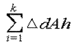
control unit 18 diagnoses that a lithium precipitation abnormality occurs inside the battery, outputs the diagnosis result through thedisplay 20, and terminates the diagnosis process. Since lithium is precipitated on the negative electrode of the lithium polymer battery used in this experiment, it may be found that the diagnostic accuracy of the present disclosure is high. -
FIG. 7 is a graph showing the change in data measured in another experimental example to which the battery abnormality diagnosing method according to an embodiment of the present disclosure is applied. - In
FIG. 7 ,Graph ① is the same asGraph ① of the experimental example described above. Graph ①' is a graph showing the measurement results of the charge capacity (ChgAh[k]) and the discharge capacity (DchgAh[k]) when a current measuring unit having a current measurement value error different from that of the experimental example described above is used. In this experimental example, the error of the discharge current measurement value is larger than that of the experimental example described above. Therefore, the graph of the discharge capacity (DchgAh[k]) is shifted upward compared to the experimental example described above. - Graphs (2) and (2)' are graphs showing a capacity difference (dAh[k]) for each charge/discharge cycle,
Graphs ③ and ③' are graphs showing a capacity difference change amount (△dAh[k]) for each charge/discharge cycle, andGraphs ④ and ④' are graphs showing an accumulated capacity difference change amount (
- Graphs (2), ③ and ④ are calculated using the data of
Graph ①, and Graphs ②', ③' and ④' are calculated using the data of Graph ①'. - As shown in
FIG. 7 , Graphs (2), ③, and ④ and Graphs (2)', ③', and ④' are substantially the same. Therefore, even if the discharge current value has a measurement error, thecontrol unit 18 performs the 13th charge/discharge cycle regardless of the magnitude of the error, then diagnoses that a lithium precipitation abnormality occurs inside the battery, outputs the diagnosis result through thedisplay 20, and terminates the diagnosis process. From these experimental results, it may be found that the present disclosure can reliably diagnose a lithium precipitation abnormality regardless of the error of the current measurement value. - Preferably, the battery
abnormality diagnosing apparatus 10 according to an embodiment of the present disclosure may be included in a diagnosing system for diagnosing whether thebattery 11 is abnormal. The diagnosing system may be operated by an electric vehicle maintenance shop, a battery manufacturer, or a battery maintenance company. - Preferably, the diagnosing system may be used for diagnosing abnormality of a battery installed in an electric vehicle or an energy storage system, or for diagnosing abnormality of a battery of a newly developed model produced by a battery manufacturer. In particular, in the latter case, before commercializing a battery of a newly developed model, the battery
abnormality diagnosing apparatus 10 can be used to examine whether the battery contains a structural weakness that causes lithium precipitation. - Alternatively, the battery
abnormality diagnosing apparatus 10 may be included in a control element of a system in which thebattery 11 is installed. - In one example, the battery
abnormality diagnosing apparatus 10 may be included in a control system of an electric vehicle. In this case, the batteryabnormality diagnosing apparatus 10 may collect data on the charge capacity and discharge capacity of the battery in the process of charging and discharging the battery mounted in the electric vehicle, diagnose a lithium precipitation abnormality using the collected data, and output the diagnosis result to an integrated control display of the electric vehicle. - In the present disclosure, the electric vehicle refers to a vehicle driven by a motor, such as an electric vehicle, a hybrid electric vehicle, or a plug-in hybrid vehicle. The vehicle may be two-wheeled, three-wheeled or four-wheeled.
- In another example, the battery
abnormality diagnosing apparatus 10 may be included in a control system of an energy storage system. In this case, the batteryabnormality diagnosing apparatus 10 may collect data on the charge capacity and discharge capacity of the battery in the process of charging and discharging the energy storage system, diagnose a lithium precipitation abnormality using the collected data, and output the diagnosis result through a display of an integrated management computer accessible by an operator. - Users of electric vehicles or operators of energy storage systems may take appropriate safety measures when the diagnosis result of lithium precipitation abnormality is output through the display. In one example, a user of an electric vehicle may visit a maintenance shop and receive an inspection. In another example, an operator of an energy storage system may replace a corresponding battery with a new battery.
- In the present disclosure, the
control unit 18 may be a control circuit. Thecontrol unit 18 may optionally include a processor, an application-specific integrated circuit (ASIC), other chipsets, logic circuits, registers, communication modems, data processing devices, etc. known in the art to execute the various control logics described above. Also, when the control logic is implemented as software, thecontrol unit 18 may be implemented as a set of program modules. At this time, the program module may be stored in a memory and executed by the processor. The memory may be provided inside or outside the processor, and may be connected to the processor by various well-known computer components. Also, the memory may be included in thestorage unit 17 of the present disclosure. Also, the memory generically refers to a device that stores information regardless of the type of device, and does not refer to a specific memory device. - One or more of the various control logics of the
control unit 18 are combined, and the combined control logics may be written in a computer-readable code system and recorded on a computer-readable recording medium. The type of the recording medium is not particularly limited as long as it can be accessed by a processor included in a computer. As an example, the recording medium includes at least one selected from the group including a ROM, a RAM, a register, a CD-ROM, a magnetic tape, a hard disk, a floppy disk, and an optical data recording device. In addition, the code system may be distributed and stored and executed in computers connected through a network. In addition, functional programs, codes and code segments for implementing the combined control logics may be easily inferred by programmers in the art to which the present disclosure belongs. - In describing various embodiments of the present disclosure, elements named `... unit' should be understood as functionally distinct elements rather than physically distinct elements. Thus, each component may be selectively integrated with other components or each component may be divided into sub-components for efficient execution of control logic(s). However, it is obvious to those skilled in the art that even if the components are integrated or divided, if the same function can be recognized, the integrated or divided components should also be interpreted as falling within the scope of the present disclosure.
- The present disclosure has been described in detail. However, it should be understood that the detailed description and specific examples, while indicating preferred embodiments of the disclosure, are given by way of illustration only, since various changes and modifications within the scope of the disclosure will become apparent to those skilled in the art from this detailed description.
Claims (18)
- A battery abnormality diagnosing apparatus, comprising:a current measuring unit configured to measure a charging current or a discharging current of a battery; anda control unit operably coupled with the current measuring unit and configured to diagnose a lithium precipitation abnormality while performing a plurality of charge/discharge cycles for the battery,wherein the control unit is configured to receive a current measurement value from the current measuring unit in a kth (k is a natural number greater than or equal to 2) charge/discharge cycle to calculate a charge capacity and a discharge capacity, determine a capacity difference corresponding to a difference between the charge capacity and the discharge capacity, determine a kth capacity difference change amount by subtracting the capacity difference of the kth charge/discharge cycle from a capacity difference of a k-1th charge/discharge cycle, update an accumulated capacity difference change amount by adding the kth capacity difference change amount to the accumulated capacity difference change amount, and diagnose that a lithium precipitation abnormality occurs when the updated accumulated capacity difference change amount is greater than or equal to a threshold value.
- The battery abnormality diagnosing apparatus according to claim 1,
wherein the control unit is configured to update the accumulated capacity difference change amount by adding the kth capacity difference change amount to the accumulated capacity difference change amount when the kth capacity difference change amount is greater than a reference value. - The battery abnormality diagnosing apparatus according to claim 1,
wherein the control unit is configured to update the accumulated capacity difference change amount by adding the kth capacity difference change amount to the accumulated capacity difference change amount when both the k-1th capacity difference change amount and the kth capacity difference change amount are greater than a reference value. - The battery abnormality diagnosing apparatus according to claim 1,
wherein the control unit is configured to assign an initial value of 0 to the accumulated capacity difference change amount when the kth capacity difference change amount is less than or equal to a reference value. - The battery abnormality diagnosing apparatus according to claim 1, wherein the reference value is 0.
- The battery abnormality diagnosing apparatus according to claim 1,
wherein when performing each charge/discharge cycle, the control unit is configured to perform the charge cycles in the same charging voltage section and perform the discharge cycles in the same discharging voltage section. - The battery abnormality diagnosing apparatus according to claim 1, wherein when performing each charge/discharge cycle, the control unit is configured to perform the charge cycles in the same charging voltage section and perform the discharge cycles in the same discharge capacity condition.
- The battery abnormality diagnosing apparatus according to claim 1, further comprising:a display coupled to the control unit,wherein the control unit is configured to diagnose that a lithium precipitation abnormality occurs when the accumulated capacity difference change amount is greater than or equal to the threshold value and output a diagnosis result through the display.
- A system, comprising the battery abnormality diagnosing apparatus according to any one of claims 1 to 8.
- An electric vehicle, comprising the battery abnormality diagnosing apparatus according to any one of claims 1 to 8.
- A battery abnormality diagnosing method for diagnosing whether a battery is abnormal by performing a plurality of charge/discharge cycles for the battery, comprising:(a) receiving a current measurement value from a current measuring unit in a kth (k is a natural number greater than or equal to 2) charge/discharge cycle to calculate a charge capacity and a discharge capacity;(b) determining a capacity difference corresponding to a difference between the charge capacity and the discharge capacity;(c) determining a kth capacity difference change amount by subtracting the capacity difference of the kth charge/discharge cycle from a capacity difference of a k-1th charge/discharge cycle;(d) updating an accumulated capacity difference change amount by adding the kth capacity difference change amount to the accumulated capacity difference change amount; and(e) diagnosing that a lithium precipitation abnormality occurs when the updated accumulated capacity difference change amount is greater than or equal to a threshold value.
- The battery abnormality diagnosing method according to claim 11,
wherein in the step (d), the accumulated capacity difference change amount is updated by adding the kth capacity difference change amount to the accumulated capacity difference change amount when the kth capacity difference change amount is greater than a reference value. - The battery abnormality diagnosing method according to claim 11,
wherein in the step (d), the accumulated capacity difference change amount is updated by adding the kth capacity difference change amount to the accumulated capacity difference change amount when both the k-1th capacity difference change amount and the kth capacity difference change amount are greater than a reference value. - The battery abnormality diagnosing method according to claim 11, further comprising:
assigning an initial value of 0 to the accumulated capacity difference change amount when the kth capacity difference change amount is less than or equal to a reference value. - The battery abnormality diagnosing method according to claim 11, wherein the reference value is 0.
- The battery abnormality diagnosing method according to claim 11,
wherein in the step (a), when performing each charge/discharge cycle, the charge cycles are performed in the same charging voltage section and the discharge cycles are performed in the same discharging voltage section. - The battery abnormality diagnosing method according to claim 11,
wherein in the step (a), when performing each charge/discharge cycle, the charge cycles are performed in the same charging voltage section and the discharge cycles are performed in the same discharge capacity condition. - The battery abnormality diagnosing method according to claim 11, further comprising:
diagnosing that a lithium precipitation abnormality occurs when the accumulated capacity difference change amount increases to be greater than or equal to the threshold value and outputting a diagnosis result through a display.
Applications Claiming Priority (3)
| Application Number | Priority Date | Filing Date | Title |
|---|---|---|---|
| KR20210166209 | 2021-11-26 | ||
| KR1020220157731A KR20230078543A (en) | 2021-11-26 | 2022-11-22 | Apparatus of Diagnosing Abnormality of Battery and Method thereof |
| PCT/KR2022/018592 WO2023096335A1 (en) | 2021-11-26 | 2022-11-23 | Apparatus and method for diagnosing abnormality of battery |
Publications (3)
| Publication Number | Publication Date |
|---|---|
| EP4343349A1 true EP4343349A1 (en) | 2024-03-27 |
| EP4343349A4 EP4343349A4 (en) | 2024-11-20 |
| EP4343349B1 EP4343349B1 (en) | 2025-08-27 |
Family
ID=86540053
Family Applications (1)
| Application Number | Title | Priority Date | Filing Date |
|---|---|---|---|
| EP22899017.2A Active EP4343349B1 (en) | 2021-11-26 | 2022-11-23 | Battery abnormality diagnosing apparatus and method |
Country Status (7)
| Country | Link |
|---|---|
| US (1) | US20240272227A1 (en) |
| EP (1) | EP4343349B1 (en) |
| JP (1) | JP7556618B2 (en) |
| ES (1) | ES3041820T3 (en) |
| HU (1) | HUE073206T2 (en) |
| PL (1) | PL4343349T3 (en) |
| WO (1) | WO2023096335A1 (en) |
Families Citing this family (1)
| Publication number | Priority date | Publication date | Assignee | Title |
|---|---|---|---|---|
| KR20220167847A (en) * | 2021-06-14 | 2022-12-22 | 주식회사 엘지에너지솔루션 | Battery management system, battery pack, electric vehicle and battery management method |
Family Cites Families (11)
| Publication number | Priority date | Publication date | Assignee | Title |
|---|---|---|---|---|
| CN102150321B (en) * | 2009-10-01 | 2014-02-26 | 丰田自动车株式会社 | Nonaqueous electrolyte solution type lithium-ion secondary battery system, method for determining lithium precipitation by the system, and vehicle having the system mounted therein |
| JP5341823B2 (en) * | 2010-06-07 | 2013-11-13 | トヨタ自動車株式会社 | Lithium ion secondary battery degradation judgment system and degradation judgment method |
| JP5699970B2 (en) * | 2012-03-16 | 2015-04-15 | トヨタ自動車株式会社 | Lithium ion secondary battery system and deposition determination method |
| JP6535890B2 (en) * | 2015-03-13 | 2019-07-03 | パナソニックIpマネジメント株式会社 | Battery management device and power supply device |
| JP2017117519A (en) | 2015-12-21 | 2017-06-29 | トヨタ自動車株式会社 | Lithium deposition amount estimation method |
| CN107438917B (en) * | 2016-07-01 | 2019-09-10 | 深圳市大疆创新科技有限公司 | Metal battery and its battery management system, control method |
| JP7286336B2 (en) | 2019-02-12 | 2023-06-05 | 一般財団法人電力中央研究所 | Method for detecting signs of occurrence of dendrites in batteries |
| JP7042228B2 (en) * | 2019-02-28 | 2022-03-25 | 本田技研工業株式会社 | Monitoring device and monitoring method |
| JP7224227B2 (en) * | 2019-04-05 | 2023-02-17 | 本田技研工業株式会社 | METAL LITHIUM DEPOSITION DETECTION DEVICE AND METHOD FOR SECONDARY BATTERY |
| US11750012B2 (en) | 2019-09-29 | 2023-09-05 | Ningde Amperex Technology Limited | Electronic device and method for charging a battery |
| KR102520923B1 (en) | 2021-05-21 | 2023-04-11 | 현대두산인프라코어(주) | Method for state estimation of construction machinary |
-
2022
- 2022-11-23 ES ES22899017T patent/ES3041820T3/en active Active
- 2022-11-23 PL PL22899017.2T patent/PL4343349T3/en unknown
- 2022-11-23 HU HUE22899017A patent/HUE073206T2/en unknown
- 2022-11-23 WO PCT/KR2022/018592 patent/WO2023096335A1/en not_active Ceased
- 2022-11-23 EP EP22899017.2A patent/EP4343349B1/en active Active
- 2022-11-23 JP JP2023549103A patent/JP7556618B2/en active Active
- 2022-11-23 US US18/566,723 patent/US20240272227A1/en active Pending
Also Published As
| Publication number | Publication date |
|---|---|
| ES3041820T3 (en) | 2025-11-14 |
| EP4343349A4 (en) | 2024-11-20 |
| EP4343349B1 (en) | 2025-08-27 |
| HUE073206T2 (en) | 2026-01-28 |
| JP7556618B2 (en) | 2024-09-26 |
| WO2023096335A1 (en) | 2023-06-01 |
| JP2024507499A (en) | 2024-02-20 |
| PL4343349T3 (en) | 2025-11-12 |
| US20240272227A1 (en) | 2024-08-15 |
Similar Documents
| Publication | Publication Date | Title |
|---|---|---|
| KR102943076B1 (en) | Apparatus of Detecting Abnormal Portent Cell in Batter Pack and Method thereof | |
| US12372587B2 (en) | Battery cell diagnosing apparatus and method | |
| US8148993B2 (en) | Abnormality detecting device, abnormality detecting method, and computer readable medium storing an abnormality detecting program | |
| JP7436690B2 (en) | Battery system diagnostic device and method | |
| KR20230078543A (en) | Apparatus of Diagnosing Abnormality of Battery and Method thereof | |
| EP3985403B1 (en) | Apparatus and method for diagnosing failure of switch unit included in multi battery pack | |
| US11929472B2 (en) | Battery diagnosing apparatus and method | |
| CN115398259B (en) | Devices and methods for diagnosing battery status | |
| KR20190069894A (en) | Apparatus and method for recalibrating SOC of secondary battery cell | |
| EP4343349B1 (en) | Battery abnormality diagnosing apparatus and method | |
| CN114616390B (en) | Method and system for predicting engine starting performance of an electrical energy storage system | |
| US11959972B2 (en) | Battery diagnosing apparatus and method | |
| CN117355760A (en) | Devices and methods for diagnosing battery abnormalities | |
| WO2022259973A1 (en) | Battery abnormality detecting device, and battery abnormality detecting method | |
| JP7823991B2 (en) | Battery internal short circuit diagnosis method and battery system using the method | |
| EP4697042A1 (en) | Battery diagnostic device, and operation method thereof | |
| CN118810547A (en) | Vehicle, battery management system, and battery health status detection method and device | |
| KR102888925B1 (en) | Battery diagnostic device and method | |
| JP2001196100A (en) | Device for determining memory effect of secondary battery and device for detecting remaining capacity of secondary battery | |
| CN117396771A (en) | A battery testing method, testing equipment, battery management system and storage medium | |
| KR20260051506A (en) | Apparatus and method for diagnosing battery | |
| CN120552609A (en) | Vehicle control device, vehicle control system, and vehicle control method | |
| KR20250079622A (en) | Apparatus for managing a battery and method thereof | |
| CN120660008A (en) | Battery diagnosis device and battery diagnosis method | |
| KR20250010974A (en) | Apparatus for managing battery and operating method of the same |
Legal Events
| Date | Code | Title | Description |
|---|---|---|---|
| STAA | Information on the status of an ep patent application or granted ep patent |
Free format text: STATUS: THE INTERNATIONAL PUBLICATION HAS BEEN MADE |
|
| PUAI | Public reference made under article 153(3) epc to a published international application that has entered the european phase |
Free format text: ORIGINAL CODE: 0009012 |
|
| STAA | Information on the status of an ep patent application or granted ep patent |
Free format text: STATUS: REQUEST FOR EXAMINATION WAS MADE |
|
| 17P | Request for examination filed |
Effective date: 20231219 |
|
| AK | Designated contracting states |
Kind code of ref document: A1 Designated state(s): AL AT BE BG CH CY CZ DE DK EE ES FI FR GB GR HR HU IE IS IT LI LT LU LV MC ME MK MT NL NO PL PT RO RS SE SI SK SM TR |
|
| REG | Reference to a national code |
Ipc: G01R0031387000 Ref country code: DE Ref legal event code: R079 Ref document number: 602022020474 Country of ref document: DE Free format text: PREVIOUS MAIN CLASS: G01R0031367000 |
|
| A4 | Supplementary search report drawn up and despatched |
Effective date: 20241023 |
|
| RIC1 | Information provided on ipc code assigned before grant |
Ipc: H01M 10/44 20060101ALI20241017BHEP Ipc: H01M 10/48 20060101ALI20241017BHEP Ipc: H02J 7/00 20060101ALI20241017BHEP Ipc: G01R 31/382 20190101ALI20241017BHEP Ipc: G01R 31/392 20190101ALI20241017BHEP Ipc: G01R 31/387 20190101AFI20241017BHEP |
|
| DAV | Request for validation of the european patent (deleted) | ||
| DAX | Request for extension of the european patent (deleted) | ||
| GRAP | Despatch of communication of intention to grant a patent |
Free format text: ORIGINAL CODE: EPIDOSNIGR1 |
|
| STAA | Information on the status of an ep patent application or granted ep patent |
Free format text: STATUS: GRANT OF PATENT IS INTENDED |
|
| INTG | Intention to grant announced |
Effective date: 20250408 |
|
| P01 | Opt-out of the competence of the unified patent court (upc) registered |
Free format text: CASE NUMBER: APP_21355/2025 Effective date: 20250506 |
|
| GRAS | Grant fee paid |
Free format text: ORIGINAL CODE: EPIDOSNIGR3 |
|
| GRAA | (expected) grant |
Free format text: ORIGINAL CODE: 0009210 |
|
| STAA | Information on the status of an ep patent application or granted ep patent |
Free format text: STATUS: THE PATENT HAS BEEN GRANTED |
|
| AK | Designated contracting states |
Kind code of ref document: B1 Designated state(s): AL AT BE BG CH CY CZ DE DK EE ES FI FR GB GR HR HU IE IS IT LI LT LU LV MC ME MK MT NL NO PL PT RO RS SE SI SK SM TR |
|
| REG | Reference to a national code |
Ref country code: CH Ref legal event code: EP |
|
| REG | Reference to a national code |
Ref country code: DE Ref legal event code: R096 Ref document number: 602022020474 Country of ref document: DE |
|
| REG | Reference to a national code |
Ref country code: IE Ref legal event code: FG4D |
|
| REG | Reference to a national code |
Ref country code: SE Ref legal event code: TRGR |
|
| REG | Reference to a national code |
Ref country code: ES Ref legal event code: FG2A Ref document number: 3041820 Country of ref document: ES Kind code of ref document: T3 Effective date: 20251114 |
|
| PGFP | Annual fee paid to national office [announced via postgrant information from national office to epo] |
Ref country code: HU Payment date: 20251127 Year of fee payment: 4 |
|
| REG | Reference to a national code |
Ref country code: NL Ref legal event code: MP Effective date: 20250827 |
|
| PG25 | Lapsed in a contracting state [announced via postgrant information from national office to epo] |
Ref country code: IS Free format text: LAPSE BECAUSE OF FAILURE TO SUBMIT A TRANSLATION OF THE DESCRIPTION OR TO PAY THE FEE WITHIN THE PRESCRIBED TIME-LIMIT Effective date: 20251227 |
|
| PGFP | Annual fee paid to national office [announced via postgrant information from national office to epo] |
Ref country code: DE Payment date: 20251020 Year of fee payment: 4 |
|
| PG25 | Lapsed in a contracting state [announced via postgrant information from national office to epo] |
Ref country code: NO Free format text: LAPSE BECAUSE OF FAILURE TO SUBMIT A TRANSLATION OF THE DESCRIPTION OR TO PAY THE FEE WITHIN THE PRESCRIBED TIME-LIMIT Effective date: 20251127 |
|
| REG | Reference to a national code |
Ref country code: LT Ref legal event code: MG9D |
|
| PG25 | Lapsed in a contracting state [announced via postgrant information from national office to epo] |
Ref country code: PT Free format text: LAPSE BECAUSE OF FAILURE TO SUBMIT A TRANSLATION OF THE DESCRIPTION OR TO PAY THE FEE WITHIN THE PRESCRIBED TIME-LIMIT Effective date: 20251229 |
|
| PG25 | Lapsed in a contracting state [announced via postgrant information from national office to epo] |
Ref country code: FI Free format text: LAPSE BECAUSE OF FAILURE TO SUBMIT A TRANSLATION OF THE DESCRIPTION OR TO PAY THE FEE WITHIN THE PRESCRIBED TIME-LIMIT Effective date: 20250827 |
|
| PG25 | Lapsed in a contracting state [announced via postgrant information from national office to epo] |
Ref country code: HR Free format text: LAPSE BECAUSE OF FAILURE TO SUBMIT A TRANSLATION OF THE DESCRIPTION OR TO PAY THE FEE WITHIN THE PRESCRIBED TIME-LIMIT Effective date: 20250827 Ref country code: NL Free format text: LAPSE BECAUSE OF FAILURE TO SUBMIT A TRANSLATION OF THE DESCRIPTION OR TO PAY THE FEE WITHIN THE PRESCRIBED TIME-LIMIT Effective date: 20250827 |
|
| PGFP | Annual fee paid to national office [announced via postgrant information from national office to epo] |
Ref country code: FR Payment date: 20251021 Year of fee payment: 4 |
|
| PG25 | Lapsed in a contracting state [announced via postgrant information from national office to epo] |
Ref country code: GR Free format text: LAPSE BECAUSE OF FAILURE TO SUBMIT A TRANSLATION OF THE DESCRIPTION OR TO PAY THE FEE WITHIN THE PRESCRIBED TIME-LIMIT Effective date: 20251128 |
|
| PGFP | Annual fee paid to national office [announced via postgrant information from national office to epo] |
Ref country code: BE Payment date: 20251020 Year of fee payment: 4 |
|
| PGFP | Annual fee paid to national office [announced via postgrant information from national office to epo] |
Ref country code: SE Payment date: 20251021 Year of fee payment: 4 |
|
| PG25 | Lapsed in a contracting state [announced via postgrant information from national office to epo] |
Ref country code: LV Free format text: LAPSE BECAUSE OF FAILURE TO SUBMIT A TRANSLATION OF THE DESCRIPTION OR TO PAY THE FEE WITHIN THE PRESCRIBED TIME-LIMIT Effective date: 20250827 |
|
| PG25 | Lapsed in a contracting state [announced via postgrant information from national office to epo] |
Ref country code: BG Free format text: LAPSE BECAUSE OF FAILURE TO SUBMIT A TRANSLATION OF THE DESCRIPTION OR TO PAY THE FEE WITHIN THE PRESCRIBED TIME-LIMIT Effective date: 20250827 |
|
| PGFP | Annual fee paid to national office [announced via postgrant information from national office to epo] |
Ref country code: PL Payment date: 20251020 Year of fee payment: 4 |
|
| PG25 | Lapsed in a contracting state [announced via postgrant information from national office to epo] |
Ref country code: RS Free format text: LAPSE BECAUSE OF FAILURE TO SUBMIT A TRANSLATION OF THE DESCRIPTION OR TO PAY THE FEE WITHIN THE PRESCRIBED TIME-LIMIT Effective date: 20251127 |
|
| REG | Reference to a national code |
Ref country code: HU Ref legal event code: AG4A Ref document number: E073206 Country of ref document: HU |
|
| PGFP | Annual fee paid to national office [announced via postgrant information from national office to epo] |
Ref country code: ES Payment date: 20251215 Year of fee payment: 4 |
|
| REG | Reference to a national code |
Ref country code: AT Ref legal event code: MK05 Ref document number: 1830491 Country of ref document: AT Kind code of ref document: T Effective date: 20250827 |
|
| PG25 | Lapsed in a contracting state [announced via postgrant information from national office to epo] |
Ref country code: RO Free format text: LAPSE BECAUSE OF FAILURE TO SUBMIT A TRANSLATION OF THE DESCRIPTION OR TO PAY THE FEE WITHIN THE PRESCRIBED TIME-LIMIT Effective date: 20250827 |
|
| PG25 | Lapsed in a contracting state [announced via postgrant information from national office to epo] |
Ref country code: SM Free format text: LAPSE BECAUSE OF FAILURE TO SUBMIT A TRANSLATION OF THE DESCRIPTION OR TO PAY THE FEE WITHIN THE PRESCRIBED TIME-LIMIT Effective date: 20250827 |
|
| PG25 | Lapsed in a contracting state [announced via postgrant information from national office to epo] |
Ref country code: DK Free format text: LAPSE BECAUSE OF FAILURE TO SUBMIT A TRANSLATION OF THE DESCRIPTION OR TO PAY THE FEE WITHIN THE PRESCRIBED TIME-LIMIT Effective date: 20250827 |
|
| PG25 | Lapsed in a contracting state [announced via postgrant information from national office to epo] |
Ref country code: AT Free format text: LAPSE BECAUSE OF FAILURE TO SUBMIT A TRANSLATION OF THE DESCRIPTION OR TO PAY THE FEE WITHIN THE PRESCRIBED TIME-LIMIT Effective date: 20250827 |
|
| PG25 | Lapsed in a contracting state [announced via postgrant information from national office to epo] |
Ref country code: IT Free format text: LAPSE BECAUSE OF FAILURE TO SUBMIT A TRANSLATION OF THE DESCRIPTION OR TO PAY THE FEE WITHIN THE PRESCRIBED TIME-LIMIT Effective date: 20250827 |
|
| PG25 | Lapsed in a contracting state [announced via postgrant information from national office to epo] |
Ref country code: CZ Free format text: LAPSE BECAUSE OF FAILURE TO SUBMIT A TRANSLATION OF THE DESCRIPTION OR TO PAY THE FEE WITHIN THE PRESCRIBED TIME-LIMIT Effective date: 20250827 |
|
| PG25 | Lapsed in a contracting state [announced via postgrant information from national office to epo] |
Ref country code: SK Free format text: LAPSE BECAUSE OF FAILURE TO SUBMIT A TRANSLATION OF THE DESCRIPTION OR TO PAY THE FEE WITHIN THE PRESCRIBED TIME-LIMIT Effective date: 20250827 Ref country code: EE Free format text: LAPSE BECAUSE OF FAILURE TO SUBMIT A TRANSLATION OF THE DESCRIPTION OR TO PAY THE FEE WITHIN THE PRESCRIBED TIME-LIMIT Effective date: 20250827 |