EP4343270A1 - Magnetic field generator and motion capture system using the same - Google Patents
Magnetic field generator and motion capture system using the same Download PDFInfo
- Publication number
- EP4343270A1 EP4343270A1 EP23199330.4A EP23199330A EP4343270A1 EP 4343270 A1 EP4343270 A1 EP 4343270A1 EP 23199330 A EP23199330 A EP 23199330A EP 4343270 A1 EP4343270 A1 EP 4343270A1
- Authority
- EP
- European Patent Office
- Prior art keywords
- magnetic field
- solenoid coil
- field generator
- signal
- magnetic
- Prior art date
- Legal status (The legal status is an assumption and is not a legal conclusion. Google has not performed a legal analysis and makes no representation as to the accuracy of the status listed.)
- Granted
Links
Images


Classifications
-
- H—ELECTRICITY
- H01—ELECTRIC ELEMENTS
- H01F—MAGNETS; INDUCTANCES; TRANSFORMERS; SELECTION OF MATERIALS FOR THEIR MAGNETIC PROPERTIES
- H01F7/00—Magnets
- H01F7/06—Electromagnets; Actuators including electromagnets
- H01F7/20—Electromagnets; Actuators including electromagnets without armatures
-
- G—PHYSICS
- G01—MEASURING; TESTING
- G01B—MEASURING LENGTH, THICKNESS OR SIMILAR LINEAR DIMENSIONS; MEASURING ANGLES; MEASURING AREAS; MEASURING IRREGULARITIES OF SURFACES OR CONTOURS
- G01B7/00—Measuring arrangements characterised by the use of electric or magnetic techniques
- G01B7/003—Measuring arrangements characterised by the use of electric or magnetic techniques for measuring position, not involving coordinate determination
-
- G—PHYSICS
- G01—MEASURING; TESTING
- G01P—MEASURING LINEAR OR ANGULAR SPEED, ACCELERATION, DECELERATION, OR SHOCK; INDICATING PRESENCE, ABSENCE, OR DIRECTION, OF MOVEMENT
- G01P13/00—Indicating or recording presence, absence, or direction, of movement
-
- G—PHYSICS
- G06—COMPUTING OR CALCULATING; COUNTING
- G06F—ELECTRIC DIGITAL DATA PROCESSING
- G06F3/00—Input arrangements for transferring data to be processed into a form capable of being handled by the computer; Output arrangements for transferring data from processing unit to output unit, e.g. interface arrangements
- G06F3/01—Input arrangements or combined input and output arrangements for interaction between user and computer
- G06F3/011—Arrangements for interaction with the human body, e.g. for user immersion in virtual reality
-
- G—PHYSICS
- G06—COMPUTING OR CALCULATING; COUNTING
- G06F—ELECTRIC DIGITAL DATA PROCESSING
- G06F3/00—Input arrangements for transferring data to be processed into a form capable of being handled by the computer; Output arrangements for transferring data from processing unit to output unit, e.g. interface arrangements
- G06F3/01—Input arrangements or combined input and output arrangements for interaction between user and computer
- G06F3/011—Arrangements for interaction with the human body, e.g. for user immersion in virtual reality
- G06F3/014—Hand-worn input/output arrangements, e.g. data gloves
Definitions
- the present disclosure relates to a magnetic field generator and a motion capture system using the same and, more particularly, to a magnetic field generator using a solenoid coil and a motion capture system using such a magnetic field generator.
- JP 04-008342A discloses a system that identifies the position of an object to be detected using a solenoid coil.
- a magnetic field generator includes a solenoid coil, a soft magnetic body disposed in the inner diameter area of the solenoid coil, and a signal generating part that supplies an AC signal to the solenoid coil.
- a motion capture system includes the magnetic field generator and a plurality of magnetic sensors configured to detect a magnetic field generated by the solenoid coil and disposed in mutually different spatial positions.
- An object of the present disclosure is to provide a noise suppression sheet having a higher noise suppression effect.
- FIG. 1 is a schematic view for explaining the configuration of a motion capture system 10 according to an embodiment of the present disclosure.
- the motion capture system 10 includes a plurality of magnetic sensors 20 and a plurality of magnetic field generators 100 positioned in a space where the magnetic sensors 20 are arranged.
- the plurality of magnetic sensors 20 are arranged on a wall surface 11 constituting the XY plane, a wall surface 12 constituting the XZ plane, and a wall surface 13 constituting the YX plane, and the plurality of magnetic field generators 100 are positioned in a space surrounded by the wall surfaces 11 to 13.
- the plurality of magnetic sensors 20 are arranged at mutually different spatial positions.
- the magnetic field generators 100 each have a cylindrical shape wearable on a finger or a wrist of a human body 30, for example.
- one magnetic field generator 100 is worn on the thumb of the human body 30, two magnetic field generators 100 are worn on each of the index, middle, ring, and little fingers, and one magnetic field generator 100 is worn on the wrist.
- the number of the magnetic field generators 100 need not necessarily be plural in the present disclosure, it is preferable to use a plurality of the magnetic field generators 100 in order to detect the motion of a movable part such as a finger.
- FIG. 3 is a schematic perspective view illustrating the structure of the magnetic field generator 100.
- the magnetic field generator 100 incudes a solenoid coil 110 and a soft magnetic body 120 disposed in the inner diameter area of the solenoid coil 110.
- the soft magnetic body 120 is made of a high permeability material such as permalloy and has a cylindrical shape disposed along the inner peripheral wall of the solenoid coil 110. This allows the magnetic field generator 100 to be worn on a finger or the like of the human body 30, as illustrated in FIG. 2 . For example, when the magnetic field generator 100 is worn on a finger of the human body 30, the soft magnetic body 120 is positioned between the finger and the solenoid coil 110.
- the soft magnetic body 120 acts to enhance magnetic flux density of a magnetic field generated from the solenoid coil 110 to expand the reach of the magnetic field.
- the solenoid coil 110 is connected to a signal generating part 130.
- the signal generating part 130 supplies an AC signal to the solenoid coil 110 to generate an AC magnetic field.
- the signal generating parts 130 may supply AC signals S1, S2, S3, etc., of mutually different frequencies, respectively, to their corresponding solenoid coils 110.
- the plurality of solenoid coils 110 generate AC magnetic fields of mutually different frequencies.
- the plurality of magnetic sensors 20 are connected to a signal processing circuit including an A-D converter 21, a Fourier transform part 22, an analyzing part 23, and a tracking part 24.
- the A-D converter 21 acts to convert an analog signal acquired from each of the plurality of magnetic sensors 20 to a digital signal.
- the Fourier transform part 22 acts to analyze the frequency of an output signal from the A-D converter 21 to divide the output signal into signals corresponding to the individual magnetic field generators 100.
- the analyzing part 23 acts to identify the positions of the individual magnetic field generators 100 using inverse problem analysis.
- the tracking part 24 tracks the positions of the individual magnetic field generators 100 to perform 3D motion capture.
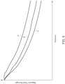
- FIG. 6 is a graph illustrating the relation between a distance from the magnetic field generator and magnetic field strength.
- the curve A denotes characteristics of the magnetic field generator 100 according to the present embodiment
- the curve B denotes characteristics of the magnetic field generator 100 from which the soft magnetic body 120 is removed
- the curve C denotes characteristics of the magnetic field generator 100 in which the soft magnetic body 120 is disposed not in the inner diameter area but in the outer peripheral area thereof.
- the magnetic field generator 100 (curve A) according to the present embodiment can obtain magnetic field strength about three times higher than that when the soft magnetic body 120 is absent (curve B), under the condition of the same distance. From the opposite viewpoint, when the magnetic field generator 100 (curve A) is used, the distance at which the same magnetic field strength can be obtained is about 1.6 times as long as when the soft magnetic body 120 is absent (curve B). When the soft magnetic body 120 is disposed at the outer peripheral area of the solenoid coil 110 (curve C), magnetic field strength to be obtained becomes significantly lower than when the soft magnetic body 120 is absent (curve B).
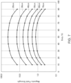
- FIG. 7 is a graph illustrating the relation between the duty ratio of the AC signal supplied from the signal generating part 130 to the solenoid coil 110 and magnetic field strength at each distance.
- the AC signal supplied from the signal generating part 130 to the solenoid coil 110 is a rectangular wave signal, and as the duty ratio thereof is closer to 50%, a higher magnetic field strength can be obtained, as illustrated in FIG. 7 .
- the AC signal to be supplied from the signal generating part 130 to the solenoid coil 110 is preferably a rectangular wave signal with a duty ratio of 30% or more and 70% or less.
- the AC signal to be supplied from the signal generating part 130 to solenoid coil 110 may be a sine wave signal, a rectangular wave signal allows achievement of higher magnetic field strength.
- the motion capture system 10 includes the plurality of magnetic sensors 20 and the magnetic field generator 100, and the magnetic field generator 100 includes the solenoid coil 110, the soft magnetic body 120 disposed in the inner diameter area of the solenoid coil 110, and the signal generating part 130 that supplies an AC signal to the solenoid coil 110.
- the reach of a magnetic field is expanded as compared with when an air-core coil is used to cover a wide area where the magnetic sensors 20 are disposed
- the motion capture system 10 according to the present embodiment is suitably used for 3D motion capture of a human body and the like.
- the technology according to the present disclosure includes the following configuration examples but not limited thereto.
- a magnetic field generator includes a solenoid coil, a soft magnetic body disposed in the inner diameter area of the solenoid coil, and a signal generating part that supplies an AC signal to the solenoid coil.
- the soft magnetic body is disposed in the inner diameter area of the solenoid coil, the reach of a magnetic field can be significantly expanded as compared with when an air-core coil is used.
- the soft magnetic body may have a cylindrical shape disposed along the inner peripheral wall of the solenoid coil. This allows the magnetic field generator to be worn on a finger, a wrist, or the like of a human body.
- the AC signal may be a rectangular wave signal with a duty ratio of 30% or more and 70% or less. This allows the reach of a magnetic field to be further expanded.
- a motion capture system includes the magnetic field generator and a plurality of magnetic sensors configured to detect a magnetic field generated by the solenoid coil and disposed in mutually different spatial positions.
- the plurality of magnetic sensors are disposed in mutually different spatial positions, thereby allowing the position of the magnetic field generator to be detected.
- the motion capture system may include a plurality of the magnetic field generators, and the signal generating parts included in the plurality of respective magnetic field generators may supply AC signals of mutually different frequencies. This allows the positions of the plurality of magnetic field generators to be detected.
- a magnetic field generator capable of expanding the reach of a magnetic field and a motion capture system using such a magnetic field generator.
Landscapes
- Engineering & Computer Science (AREA)
- Physics & Mathematics (AREA)
- General Physics & Mathematics (AREA)
- Electromagnetism (AREA)
- Theoretical Computer Science (AREA)
- General Engineering & Computer Science (AREA)
- Human Computer Interaction (AREA)
- Power Engineering (AREA)
- Magnetic Treatment Devices (AREA)
- Prostheses (AREA)
- User Interface Of Digital Computer (AREA)
- Position Input By Displaying (AREA)
- Measuring Magnetic Variables (AREA)
- Measurement And Recording Of Electrical Phenomena And Electrical Characteristics Of The Living Body (AREA)
Abstract
Description
- This application claims the benefit of
Japanese Patent Application No. 2022-152362, filed on September 26, 2022 - The present disclosure relates to a magnetic field generator and a motion capture system using the same and, more particularly, to a magnetic field generator using a solenoid coil and a motion capture system using such a magnetic field generator.
-
JP 04-008342A - However, in the system disclosed in
JP 04-008342A - It is therefore an object of the present disclosure to provide a magnetic field generator capable of expanding the reach of a magnetic field and a motion capture system using such a magnetic field generator.
- A magnetic field generator according to the present disclosure includes a solenoid coil, a soft magnetic body disposed in the inner diameter area of the solenoid coil, and a signal generating part that supplies an AC signal to the solenoid coil.
- A motion capture system according to the present disclosure includes the magnetic field generator and a plurality of magnetic sensors configured to detect a magnetic field generated by the solenoid coil and disposed in mutually different spatial positions.
- The above features and advantages of the present disclosure will be more apparent from the following description of certain preferred embodiments taken in conjunction with the accompanying drawings, in which:
-
FIG. 1 is a schematic view for explaining the configuration of amotion capture system 10 according to an embodiment of the present disclosure; -
FIG. 2 is a schematic diagram showing an example in which themagnetic field generators 100 are attached to the fingers and wrist of thehuman body 30; -
FIG. 3 is a schematic perspective view illustrating the structure of themagnetic field generator 100; -
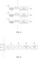
FIG. 4 is a block diagram of thesignal generating part 130 connected to thesolenoid coil 110; -
FIG. 5 is a block diagram of a signal processing circuit connected to themagnetic sensor 20; -
FIG. 6 is a graph illustrating the relation between a distance from the magnetic field generator and magnetic field strength; and -
FIG. 7 is a graph illustrating the relation between the duty ratio of the AC signal supplied from thesignal generating part 130 to thesolenoid coil 110 and magnetic field strength at each distance. - An object of the present disclosure is to provide a noise suppression sheet having a higher noise suppression effect.
-
FIG. 1 is a schematic view for explaining the configuration of amotion capture system 10 according to an embodiment of the present disclosure. - As illustrated in
FIG. 1 , themotion capture system 10 according to the present embodiment includes a plurality ofmagnetic sensors 20 and a plurality ofmagnetic field generators 100 positioned in a space where themagnetic sensors 20 are arranged. In the example ofFIG. 1 , the plurality ofmagnetic sensors 20 are arranged on awall surface 11 constituting the XY plane, awall surface 12 constituting the XZ plane, and awall surface 13 constituting the YX plane, and the plurality ofmagnetic field generators 100 are positioned in a space surrounded by thewall surfaces 11 to 13. As described above, the plurality ofmagnetic sensors 20 are arranged at mutually different spatial positions. - As illustrated in
FIG. 2 , themagnetic field generators 100 each have a cylindrical shape wearable on a finger or a wrist of ahuman body 30, for example. In the example ofFIG. 2 , onemagnetic field generator 100 is worn on the thumb of thehuman body 30, twomagnetic field generators 100 are worn on each of the index, middle, ring, and little fingers, and onemagnetic field generator 100 is worn on the wrist. Although the number of themagnetic field generators 100 need not necessarily be plural in the present disclosure, it is preferable to use a plurality of themagnetic field generators 100 in order to detect the motion of a movable part such as a finger. -
FIG. 3 is a schematic perspective view illustrating the structure of themagnetic field generator 100. - As illustrated in
FIG. 3 , themagnetic field generator 100 incudes asolenoid coil 110 and a softmagnetic body 120 disposed in the inner diameter area of thesolenoid coil 110. The softmagnetic body 120 is made of a high permeability material such as permalloy and has a cylindrical shape disposed along the inner peripheral wall of thesolenoid coil 110. This allows themagnetic field generator 100 to be worn on a finger or the like of thehuman body 30, as illustrated inFIG. 2 . For example, when themagnetic field generator 100 is worn on a finger of thehuman body 30, the softmagnetic body 120 is positioned between the finger and thesolenoid coil 110. The softmagnetic body 120 acts to enhance magnetic flux density of a magnetic field generated from thesolenoid coil 110 to expand the reach of the magnetic field. - As illustrated in
FIG. 4 , thesolenoid coil 110 is connected to asignal generating part 130. Thesignal generating part 130 supplies an AC signal to thesolenoid coil 110 to generate an AC magnetic field. When the plurality ofmagnetic field generators 100 are used simultaneously, thesignal generating parts 130 may supply AC signals S1, S2, S3, etc., of mutually different frequencies, respectively, to theircorresponding solenoid coils 110. In this case, the plurality ofsolenoid coils 110 generate AC magnetic fields of mutually different frequencies. - As illustrated in
FIG. 5 , the plurality ofmagnetic sensors 20 are connected to a signal processing circuit including anA-D converter 21, a Fouriertransform part 22, an analyzingpart 23, and atracking part 24. TheA-D converter 21 acts to convert an analog signal acquired from each of the plurality ofmagnetic sensors 20 to a digital signal. The Fouriertransform part 22 acts to analyze the frequency of an output signal from theA-D converter 21 to divide the output signal into signals corresponding to the individualmagnetic field generators 100. The analyzingpart 23 acts to identify the positions of the individualmagnetic field generators 100 using inverse problem analysis. Thetracking part 24 tracks the positions of the individualmagnetic field generators 100 to perform 3D motion capture. -
FIG. 6 is a graph illustrating the relation between a distance from the magnetic field generator and magnetic field strength. InFIG. 6 , the curve A denotes characteristics of themagnetic field generator 100 according to the present embodiment, the curve B denotes characteristics of themagnetic field generator 100 from which the softmagnetic body 120 is removed, and the curve C denotes characteristics of themagnetic field generator 100 in which the softmagnetic body 120 is disposed not in the inner diameter area but in the outer peripheral area thereof. - As can be seen from
FIG. 6 , the magnetic field generator 100 (curve A) according to the present embodiment can obtain magnetic field strength about three times higher than that when the softmagnetic body 120 is absent (curve B), under the condition of the same distance. From the opposite viewpoint, when the magnetic field generator 100 (curve A) is used, the distance at which the same magnetic field strength can be obtained is about 1.6 times as long as when the softmagnetic body 120 is absent (curve B). When the softmagnetic body 120 is disposed at the outer peripheral area of the solenoid coil 110 (curve C), magnetic field strength to be obtained becomes significantly lower than when the softmagnetic body 120 is absent (curve B). -
FIG. 7 is a graph illustrating the relation between the duty ratio of the AC signal supplied from thesignal generating part 130 to thesolenoid coil 110 and magnetic field strength at each distance. - The AC signal supplied from the
signal generating part 130 to thesolenoid coil 110 is a rectangular wave signal, and as the duty ratio thereof is closer to 50%, a higher magnetic field strength can be obtained, as illustrated inFIG. 7 . In a range of duty ratio from 30% or more to 70% or less, a significant difference is not found in the magnetic field strength to be obtained; while when the duty ratio is less than 30% or more than 70%, the magnetic field strength remarkably decreases. Thus, the AC signal to be supplied from thesignal generating part 130 to thesolenoid coil 110 is preferably a rectangular wave signal with a duty ratio of 30% or more and 70% or less. Although the AC signal to be supplied from thesignal generating part 130 tosolenoid coil 110 may be a sine wave signal, a rectangular wave signal allows achievement of higher magnetic field strength. - As described above, the
motion capture system 10 according to the present embodiment includes the plurality ofmagnetic sensors 20 and themagnetic field generator 100, and themagnetic field generator 100 includes thesolenoid coil 110, the softmagnetic body 120 disposed in the inner diameter area of thesolenoid coil 110, and thesignal generating part 130 that supplies an AC signal to thesolenoid coil 110. With this configuration, the reach of a magnetic field is expanded as compared with when an air-core coil is used to cover a wide area where themagnetic sensors 20 are disposed Thus, themotion capture system 10 according to the present embodiment is suitably used for 3D motion capture of a human body and the like. - While the preferred embodiment of the present disclosure has been described, the present disclosure is not limited to the above embodiment, and various modifications may be made within the scope of the present disclosure, and all such modifications are included in the present disclosure.
- The technology according to the present disclosure includes the following configuration examples but not limited thereto.
- A magnetic field generator according to the present disclosure includes a solenoid coil, a soft magnetic body disposed in the inner diameter area of the solenoid coil, and a signal generating part that supplies an AC signal to the solenoid coil.
- According to the present disclosure, since the soft magnetic body is disposed in the inner diameter area of the solenoid coil, the reach of a magnetic field can be significantly expanded as compared with when an air-core coil is used.
- In the present disclosure, the soft magnetic body may have a cylindrical shape disposed along the inner peripheral wall of the solenoid coil. This allows the magnetic field generator to be worn on a finger, a wrist, or the like of a human body.
- In the present disclosure, the AC signal may be a rectangular wave signal with a duty ratio of 30% or more and 70% or less. This allows the reach of a magnetic field to be further expanded.
- A motion capture system according to the present disclosure includes the magnetic field generator and a plurality of magnetic sensors configured to detect a magnetic field generated by the solenoid coil and disposed in mutually different spatial positions.
- According to the present disclosure, the plurality of magnetic sensors are disposed in mutually different spatial positions, thereby allowing the position of the magnetic field generator to be detected.
- The motion capture system according to the present disclosure may include a plurality of the magnetic field generators, and the signal generating parts included in the plurality of respective magnetic field generators may supply AC signals of mutually different frequencies. This allows the positions of the plurality of magnetic field generators to be detected.
- As described above, according to the present disclosure, there can be provided a magnetic field generator capable of expanding the reach of a magnetic field and a motion capture system using such a magnetic field generator.
Claims (5)
- A magnetic field generator comprising:a solenoid coil;a soft magnetic body disposed in an inner diameter area of the solenoid coil; anda signal generating part configured to supply an AC signal to the solenoid coil.
- The magnetic field generator as claimed in claim 1, wherein the soft magnetic body has a cylindrical shape disposed along an inner peripheral wall of the solenoid coil.
- The magnetic field generator as claimed in claim 1 or 2, wherein the AC signal is a rectangular wave signal with a duty ratio of 30% or more and 70% or less.
- A motion capture system comprising:the magnetic field generator as claimed in any one of claims 1 to 3; anda plurality of magnetic sensors configured to detect a magnetic field generated by the solenoid coil,wherein the plurality of magnetic sensors are disposed in mutually different spatial positions.
- The motion capture system as claimed in claim 4,wherein a plurality of the magnetic field generators are provided, andwherein the signal generating parts included in the plurality of respective magnetic field generators are supply AC signals of mutually different frequencies.
Applications Claiming Priority (1)
| Application Number | Priority Date | Filing Date | Title |
|---|---|---|---|
| JP2022152362A JP2024046969A (en) | 2022-09-26 | 2022-09-26 | Magnetic field generating device and motion capture system using the same |
Publications (2)
| Publication Number | Publication Date |
|---|---|
| EP4343270A1 true EP4343270A1 (en) | 2024-03-27 |
| EP4343270B1 EP4343270B1 (en) | 2026-03-11 |
Family
ID=88197226
Family Applications (1)
| Application Number | Title | Priority Date | Filing Date |
|---|---|---|---|
| EP23199330.4A Active EP4343270B1 (en) | 2022-09-26 | 2023-09-25 | Magnetic field generator and motion capture system using the same |
Country Status (4)
| Country | Link |
|---|---|
| US (1) | US12603209B2 (en) |
| EP (1) | EP4343270B1 (en) |
| JP (1) | JP2024046969A (en) |
| CN (1) | CN117766272A (en) |
Citations (5)
| Publication number | Priority date | Publication date | Assignee | Title |
|---|---|---|---|---|
| JPH048342A (en) | 1990-04-25 | 1992-01-13 | Olympus Optical Co Ltd | Inserting device into testee body |
| US5994837A (en) * | 1997-01-27 | 1999-11-30 | U.S. Philips Corporation | Electrodeless low-pressure mercury discharge lamp |
| JP2000311047A (en) * | 1999-04-28 | 2000-11-07 | Tadatoshi Goto | Intelligent glove type handprint input device |
| JP2007309690A (en) * | 2006-05-16 | 2007-11-29 | Daido Steel Co Ltd | Flaw detection method and flaw detection apparatus |
| US20200272235A1 (en) * | 2019-02-21 | 2020-08-27 | Facebook Technologies, Llc | Tracking positions of portions of a device based on detection of magnetic fields by magnetic field sensors having predetermined positions |
Family Cites Families (5)
| Publication number | Priority date | Publication date | Assignee | Title |
|---|---|---|---|---|
| JPH0799724B2 (en) * | 1985-01-28 | 1995-10-25 | 三菱電機株式会社 | Uniform magnetic field generator |
| JP3500125B2 (en) * | 2001-02-14 | 2004-02-23 | 株式会社ミツトヨ | Elastic body vibration detection system |
| JP2002299119A (en) * | 2001-04-03 | 2002-10-11 | Japan Science & Technology Corp | Magnetic field generating element without feeder |
| JP4922504B2 (en) * | 2001-06-29 | 2012-04-25 | 株式会社アミテック | Glove-type input device |
| US20220276074A1 (en) * | 2021-01-22 | 2022-09-01 | Eric HASELTINE | Systems and methods for through wall locating |
-
2022
- 2022-09-26 JP JP2022152362A patent/JP2024046969A/en active Pending
-
2023
- 2023-09-25 US US18/473,699 patent/US12603209B2/en active Active
- 2023-09-25 CN CN202311242349.1A patent/CN117766272A/en active Pending
- 2023-09-25 EP EP23199330.4A patent/EP4343270B1/en active Active
Patent Citations (5)
| Publication number | Priority date | Publication date | Assignee | Title |
|---|---|---|---|---|
| JPH048342A (en) | 1990-04-25 | 1992-01-13 | Olympus Optical Co Ltd | Inserting device into testee body |
| US5994837A (en) * | 1997-01-27 | 1999-11-30 | U.S. Philips Corporation | Electrodeless low-pressure mercury discharge lamp |
| JP2000311047A (en) * | 1999-04-28 | 2000-11-07 | Tadatoshi Goto | Intelligent glove type handprint input device |
| JP2007309690A (en) * | 2006-05-16 | 2007-11-29 | Daido Steel Co Ltd | Flaw detection method and flaw detection apparatus |
| US20200272235A1 (en) * | 2019-02-21 | 2020-08-27 | Facebook Technologies, Llc | Tracking positions of portions of a device based on detection of magnetic fields by magnetic field sensors having predetermined positions |
Non-Patent Citations (1)
| Title |
|---|
| SALEMI PARIZI FARSHID TAOYF@CSE CUHK EDU HK ET AL: "AuraRing", GETMOBILE: MOBILE COMPUTING AND COMMUNICATIONS, ACM, 2 PENN PLAZA, SUITE 701 NEW YORK NY 10121-0701 USA, vol. 25, no. 3, 11 January 2022 (2022-01-11), pages 34 - 37, XP058671667, ISSN: 2375-0529, DOI: 10.1145/3511285.3511295 * |
Also Published As
| Publication number | Publication date |
|---|---|
| EP4343270B1 (en) | 2026-03-11 |
| US12603209B2 (en) | 2026-04-14 |
| US20240105375A1 (en) | 2024-03-28 |
| CN117766272A (en) | 2024-03-26 |
| JP2024046969A (en) | 2024-04-05 |
Similar Documents
| Publication | Publication Date | Title |
|---|---|---|
| Park et al. | Acoustic fault detection technique for high-power insulators | |
| US4613817A (en) | Superconducting gradiometer coil system for an apparatus for the multi-channel measurement of weak nonstationary magnetic fields | |
| US8446147B2 (en) | Position detecting device having opposite-phase magnetic-field generating coil, medical device guiding system, position detecting method, and medical device guiding method | |
| US7969143B2 (en) | Method of tracking an object having a passive transponder attached thereto | |
| EP1974225A2 (en) | Signal analyser | |
| KR20160102780A (en) | Triaxial sensor and device including the same for measuring magnetic field | |
| Sekihara et al. | Time-frequency MEG-MUSIC algorithm | |
| US12603209B2 (en) | Magnetic field generator and motion capture system using the same | |
| EP1032891B1 (en) | Method and device for detecting and making signal shapes coincidental, said shapes being convertible into monotone and constant trajectories in a section by section manner | |
| Tymchik et al. | Distortion of phantom object's realizations in biological presence zone | |
| Bhuyan et al. | Low cost data glove for hand gesture recognition by finger bend measurement | |
| Hu et al. | A new eigenstructure method for sinusoidal signal retrieval in white noise: estimation and pattern recognition | |
| US5874831A (en) | Magnetic resonance imaging (MRI) system | |
| JP2000146509A (en) | Measurement method for magnetic motion capture device | |
| Sekihara et al. | Estimating neural sources from each time-frequency component of magnetoencephalographic data | |
| US12265141B2 (en) | Sensor and inspection device | |
| Adhikari et al. | Real-time physiological tremor estimation using recursive singular spectrum analysis | |
| Sorokin et al. | Simulation of a magnetic system with a ferromagnetic shell | |
| Matsumoto et al. | Multiple signal classification by aggregated microphones | |
| Williams et al. | Generalized broadband beamforming using a modal subspace decomposition | |
| RU2789733C1 (en) | Device for magnetometric local navigation | |
| Hamil et al. | FPGA-based hardware architecture for real-time time-frequency analysis: Applying STFT for the segmentation of non-stationary signals | |
| Bassi et al. | FBCNN: a deep neural network architecture for portable and fast brain-computer interfaces | |
| CN112578321B (en) | In-situ sound compensation digital magnetic field sensor | |
| US20240385261A1 (en) | Mems magnetometer and gradiometer arrays and patterns |
Legal Events
| Date | Code | Title | Description |
|---|---|---|---|
| PUAI | Public reference made under article 153(3) epc to a published international application that has entered the european phase |
Free format text: ORIGINAL CODE: 0009012 |
|
| STAA | Information on the status of an ep patent application or granted ep patent |
Free format text: STATUS: THE APPLICATION HAS BEEN PUBLISHED |
|
| AK | Designated contracting states |
Kind code of ref document: A1 Designated state(s): AL AT BE BG CH CY CZ DE DK EE ES FI FR GB GR HR HU IE IS IT LI LT LU LV MC ME MK MT NL NO PL PT RO RS SE SI SK SM TR |
|
| STAA | Information on the status of an ep patent application or granted ep patent |
Free format text: STATUS: REQUEST FOR EXAMINATION WAS MADE |
|
| 17P | Request for examination filed |
Effective date: 20240927 |
|
| RBV | Designated contracting states (corrected) |
Designated state(s): AL AT BE BG CH CY CZ DE DK EE ES FI FR GB GR HR HU IE IS IT LI LT LU LV MC ME MK MT NL NO PL PT RO RS SE SI SK SM TR |
|
| GRAP | Despatch of communication of intention to grant a patent |
Free format text: ORIGINAL CODE: EPIDOSNIGR1 |
|
| STAA | Information on the status of an ep patent application or granted ep patent |
Free format text: STATUS: GRANT OF PATENT IS INTENDED |
|
| RIC1 | Information provided on ipc code assigned before grant |
Ipc: G01B 7/00 20060101AFI20250903BHEP Ipc: G06F 3/01 20060101ALI20250903BHEP |
|
| INTG | Intention to grant announced |
Effective date: 20251007 |
|
| GRAJ | Information related to disapproval of communication of intention to grant by the applicant or resumption of examination proceedings by the epo deleted |
Free format text: ORIGINAL CODE: EPIDOSDIGR1 |
|
| STAA | Information on the status of an ep patent application or granted ep patent |
Free format text: STATUS: REQUEST FOR EXAMINATION WAS MADE |
|
| GRAP | Despatch of communication of intention to grant a patent |
Free format text: ORIGINAL CODE: EPIDOSNIGR1 |
|
| STAA | Information on the status of an ep patent application or granted ep patent |
Free format text: STATUS: GRANT OF PATENT IS INTENDED |
|
| INTC | Intention to grant announced (deleted) | ||
| INTG | Intention to grant announced |
Effective date: 20251209 |
|
| GRAS | Grant fee paid |
Free format text: ORIGINAL CODE: EPIDOSNIGR3 |
|
| GRAA | (expected) grant |
Free format text: ORIGINAL CODE: 0009210 |
|
| STAA | Information on the status of an ep patent application or granted ep patent |
Free format text: STATUS: THE PATENT HAS BEEN GRANTED |
|
| AK | Designated contracting states |
Kind code of ref document: B1 Designated state(s): AL AT BE BG CH CY CZ DE DK EE ES FI FR GB GR HR HU IE IS IT LI LT LU LV MC ME MK MT NL NO PL PT RO RS SE SI SK SM TR |
|
| REG | Reference to a national code |
Ref country code: CH Ref legal event code: F10 Free format text: ST27 STATUS EVENT CODE: U-0-0-F10-F00 (AS PROVIDED BY THE NATIONAL OFFICE) Effective date: 20260311 Ref country code: GB Ref legal event code: FG4D |
|
| REG | Reference to a national code |
Ref country code: DE Ref legal event code: R096 Ref document number: 602023013284 Country of ref document: DE |
|
| REG | Reference to a national code |
Ref country code: IE Ref legal event code: FG4D |