EP4343262A1 - Annular arrangement of heat exchangers - Google Patents
Annular arrangement of heat exchangers Download PDFInfo
- Publication number
- EP4343262A1 EP4343262A1 EP23187638.4A EP23187638A EP4343262A1 EP 4343262 A1 EP4343262 A1 EP 4343262A1 EP 23187638 A EP23187638 A EP 23187638A EP 4343262 A1 EP4343262 A1 EP 4343262A1
- Authority
- EP
- European Patent Office
- Prior art keywords
- heat exchanger
- cores
- inlet
- aft
- guide vanes
- Prior art date
- Legal status (The legal status is an assumption and is not a legal conclusion. Google has not performed a legal analysis and makes no representation as to the accuracy of the status listed.)
- Granted
Links
Images

Classifications
-
- F—MECHANICAL ENGINEERING; LIGHTING; HEATING; WEAPONS; BLASTING
- F28—HEAT EXCHANGE IN GENERAL
- F28D—HEAT-EXCHANGE APPARATUS, NOT PROVIDED FOR IN ANOTHER SUBCLASS, IN WHICH THE HEAT-EXCHANGE MEDIA DO NOT COME INTO DIRECT CONTACT
- F28D1/00—Heat-exchange apparatus having stationary conduit assemblies for one heat-exchange medium only, the media being in contact with different sides of the conduit wall, in which the other heat-exchange medium is a large body of fluid, e.g. domestic or motor car radiators
- F28D1/02—Heat-exchange apparatus having stationary conduit assemblies for one heat-exchange medium only, the media being in contact with different sides of the conduit wall, in which the other heat-exchange medium is a large body of fluid, e.g. domestic or motor car radiators with heat-exchange conduits immersed in the body of fluid
- F28D1/04—Heat-exchange apparatus having stationary conduit assemblies for one heat-exchange medium only, the media being in contact with different sides of the conduit wall, in which the other heat-exchange medium is a large body of fluid, e.g. domestic or motor car radiators with heat-exchange conduits immersed in the body of fluid with tubular conduits
- F28D1/053—Heat-exchange apparatus having stationary conduit assemblies for one heat-exchange medium only, the media being in contact with different sides of the conduit wall, in which the other heat-exchange medium is a large body of fluid, e.g. domestic or motor car radiators with heat-exchange conduits immersed in the body of fluid with tubular conduits the conduits being straight
- F28D1/0535—Heat-exchange apparatus having stationary conduit assemblies for one heat-exchange medium only, the media being in contact with different sides of the conduit wall, in which the other heat-exchange medium is a large body of fluid, e.g. domestic or motor car radiators with heat-exchange conduits immersed in the body of fluid with tubular conduits the conduits being straight the conduits having a non-circular cross-section
- F28D1/05366—Assemblies of conduits connected to common headers, e.g. core type radiators
-
- F—MECHANICAL ENGINEERING; LIGHTING; HEATING; WEAPONS; BLASTING
- F28—HEAT EXCHANGE IN GENERAL
- F28D—HEAT-EXCHANGE APPARATUS, NOT PROVIDED FOR IN ANOTHER SUBCLASS, IN WHICH THE HEAT-EXCHANGE MEDIA DO NOT COME INTO DIRECT CONTACT
- F28D21/00—Heat-exchange apparatus not covered by any of the groups F28D1/00 - F28D20/00
- F28D21/0001—Recuperative heat exchangers
- F28D21/0003—Recuperative heat exchangers the heat being recuperated from exhaust gases
-
- F—MECHANICAL ENGINEERING; LIGHTING; HEATING; WEAPONS; BLASTING
- F02—COMBUSTION ENGINES; HOT-GAS OR COMBUSTION-PRODUCT ENGINE PLANTS
- F02C—GAS-TURBINE PLANTS; AIR INTAKES FOR JET-PROPULSION PLANTS; CONTROLLING FUEL SUPPLY IN AIR-BREATHING JET-PROPULSION PLANTS
- F02C7/00—Features, components parts, details or accessories, not provided for in, or of interest apart form groups F02C1/00 - F02C6/00; Air intakes for jet-propulsion plants
- F02C7/08—Heating air supply before combustion, e.g. by exhaust gases
-
- F—MECHANICAL ENGINEERING; LIGHTING; HEATING; WEAPONS; BLASTING
- F02—COMBUSTION ENGINES; HOT-GAS OR COMBUSTION-PRODUCT ENGINE PLANTS
- F02C—GAS-TURBINE PLANTS; AIR INTAKES FOR JET-PROPULSION PLANTS; CONTROLLING FUEL SUPPLY IN AIR-BREATHING JET-PROPULSION PLANTS
- F02C7/00—Features, components parts, details or accessories, not provided for in, or of interest apart form groups F02C1/00 - F02C6/00; Air intakes for jet-propulsion plants
- F02C7/08—Heating air supply before combustion, e.g. by exhaust gases
- F02C7/10—Heating air supply before combustion, e.g. by exhaust gases by means of regenerative heat-exchangers
-
- F—MECHANICAL ENGINEERING; LIGHTING; HEATING; WEAPONS; BLASTING
- F28—HEAT EXCHANGE IN GENERAL
- F28D—HEAT-EXCHANGE APPARATUS, NOT PROVIDED FOR IN ANOTHER SUBCLASS, IN WHICH THE HEAT-EXCHANGE MEDIA DO NOT COME INTO DIRECT CONTACT
- F28D21/00—Heat-exchange apparatus not covered by any of the groups F28D1/00 - F28D20/00
-
- F—MECHANICAL ENGINEERING; LIGHTING; HEATING; WEAPONS; BLASTING
- F28—HEAT EXCHANGE IN GENERAL
- F28D—HEAT-EXCHANGE APPARATUS, NOT PROVIDED FOR IN ANOTHER SUBCLASS, IN WHICH THE HEAT-EXCHANGE MEDIA DO NOT COME INTO DIRECT CONTACT
- F28D21/00—Heat-exchange apparatus not covered by any of the groups F28D1/00 - F28D20/00
- F28D21/0001—Recuperative heat exchangers
- F28D21/0014—Recuperative heat exchangers the heat being recuperated from waste air or from vapors
-
- F—MECHANICAL ENGINEERING; LIGHTING; HEATING; WEAPONS; BLASTING
- F28—HEAT EXCHANGE IN GENERAL
- F28F—DETAILS OF HEAT-EXCHANGE AND HEAT-TRANSFER APPARATUS, OF GENERAL APPLICATION
- F28F9/00—Casings; Header boxes; Auxiliary supports for elements; Auxiliary members within casings
- F28F9/02—Header boxes; End plates
- F28F9/026—Header boxes; End plates with static flow control means, e.g. with means for uniformly distributing heat exchange media into conduits
- F28F9/0265—Header boxes; End plates with static flow control means, e.g. with means for uniformly distributing heat exchange media into conduits by using guiding means or impingement means inside the header box
-
- F—MECHANICAL ENGINEERING; LIGHTING; HEATING; WEAPONS; BLASTING
- F05—INDEXING SCHEMES RELATING TO ENGINES OR PUMPS IN VARIOUS SUBCLASSES OF CLASSES F01-F04
- F05D—INDEXING SCHEME FOR ASPECTS RELATING TO NON-POSITIVE-DISPLACEMENT MACHINES OR ENGINES, GAS-TURBINES OR JET-PROPULSION PLANTS
- F05D2260/00—Function
- F05D2260/20—Heat transfer, e.g. cooling
- F05D2260/213—Heat transfer, e.g. cooling by the provision of a heat exchanger within the cooling circuit
-
- F—MECHANICAL ENGINEERING; LIGHTING; HEATING; WEAPONS; BLASTING
- F28—HEAT EXCHANGE IN GENERAL
- F28D—HEAT-EXCHANGE APPARATUS, NOT PROVIDED FOR IN ANOTHER SUBCLASS, IN WHICH THE HEAT-EXCHANGE MEDIA DO NOT COME INTO DIRECT CONTACT
- F28D21/00—Heat-exchange apparatus not covered by any of the groups F28D1/00 - F28D20/00
- F28D2021/0019—Other heat exchangers for particular applications; Heat exchange systems not otherwise provided for
- F28D2021/0026—Other heat exchangers for particular applications; Heat exchange systems not otherwise provided for for combustion engines, e.g. for gas turbines or for Stirling engines
Definitions
- the embodiments relate to heat exchangers and more specifically to an annular arrangement of heat exchangers.
- Gas turbine engines are configured to exhaust waste heat during normal operation. If a significant pressure drop is avoided, the waste heat may be recaptured and utilized for increasing the efficiency of the engine operation.
- a heat exchanger including: a front end and an aft end spaced apart from each other; heat exchanger cores that are circumferentially spaced apart from each other in an annular loop such that they define circumferential gaps between adjacent pairs of the cores, wherein the cores, configured individually or in axially aligned sets, extend from the front end to the aft end and have circumferentially facing inlet sides and circumferentially facing outlet sides configured such that the inlet sides and the outlet sides from the adjacent pairs of the cores face into the same ones of the circumferential gaps; and core guide vanes disposed in the circumferential gaps, the core guide vanes have an aft portion that extends from the front end to the aft end of the heat exchanger, wherein: at the front end the heat exchanger, the core guide vanes are closer to the outlet side of the cores; and at the aft end the heat exchanger, the core guide vanes are closer to the inlet sides of the cores, whereby the core guide
- the cores are counter-flow or cross flow heat exchangers.
- the cores are rectangular shaped and have cases that include axial front surfaces; the core guide vanes each include a forward portion that extends forward from the aft portion; and the heat exchanger further includes: an annular inlet duct extending axially forward from the front end of the heat exchanger to a front end of the inlet duct, wherein the forward portion of the core guide vanes extends to the front end of the inlet duct; and duct guide vanes that extend axially forward from the inlet sides of the cores to an adjacent one of the core guide vanes, and connect over the axial front surfaces of the cores, to thereby form a flow path around the front surfaces of the cores.
- the heat exchanger has a first outer diameter
- the inlet duct tapers toward the front end of the inlet duct to a second outer diameter that is smaller than the first outer diameter
- the heat exchanger has a radial center; and the cases of the cores have radial outer surfaces located at the first outer diameter of the heat exchanger and radial inner surfaces that are spaced apart from the radial center of the heat exchanger, to thereby define a center flow passageway between the cores.
- the heat exchanger further includes: shroud sections extending between the cores, to define a radial flow boundary around the circumferential gaps.
- a gas turbine engine including: an engine inlet; an engine core located aft of the inlet; an exhaust duct located aft of the engine core; and a heat exchanger having one or more of the above disclosed aspects disposed between the engine core and the exhaust duct.
- a heat exchanger including a front end and an aft end spaced apart from each other, and the heat exchanger defining radial center and outer diameter; heat exchanger cores extending from the front end to the aft end and are disposed in an annular loop, wherein the cores have inlet sides facing radially inward, toward the radial center of the heat exchanger and outlet sides facing radially outward, toward the outer diameter of the heat exchanger.
- the cores are counter-flow or cross flow heat exchangers.
- the cores are rectangular shaped.
- the heat exchanger further includes: shroud sections disposed radially exterior to the cores to define the outer diameter of the heat exchanger, the shroud sections being configured to turn a gas flow from a radial direction at the outlet sides of the cores to an axial direction.
- the inlet sides of the cores are spaced apart from the radial center of the heat exchanger to define a center flow passageway between the cores.
- the heat exchanger further includes: a guide plate located at the aft end of the heat exchanger and within the center flow passageway, the guide plate forming a V shape with a peak directed toward the front end of the heat exchanger, whereby the guide plate is configured to turn the gas flow from the axial direction to the radial direction and guide the gas flow to the inlet sides of the cores.
- a gas turbine engine including: an engine inlet; an engine core located aft of the inlet; an exhaust duct located aft of the engine core; and a heat exchanger having one or more of the above disclosed aspects disposed between the engine core and the exhaust duct.
- the embodiments disclosed herein are directed to a configuration of a heat exchanger.
- the arrangement of the embodiments utilize an annular compact packaging configuration for the heat exchangers that provides a large flow-facing surface area, reducing pressure losses.
- the heat exchanger can be used with any heat producing device. For example, it can be used in an exhaust of an aircraft engine. In one embodiment, when used with a turbofan engine, for example, it can improve efficiency by harvesting waste heat from the exhaust stream while providing a low pressure drop.
- the heat exchanger 100 includes a front end 110 and an aft end 120 spaced apart from each other. Flow (e.g., the arrows in FIG. 1 ) moves from the front end 110 to the aft end 120.
- the heat exchanger 100 includes heat exchanger cores 130 circumferentially spaced apart from each other in an annular loop 140 such that they define circumferential gaps 150 between adjacent pairs of the cores 130.
- the cores 130 are counter-flow heat exchangers that are rectangular shaped and have cases 160 that include axial front surfaces 170 and axial aft surfaces 180. Cross flow heat exchangers are within the scope of the embodiments.
- the cores 130 are arranged in pairs 1301, 1302, in the forward F to aft A direction, e.g., relative to the axial direction 10 as show in FIG. 1 , though this is not intended on limiting the scope of the core arrangements.
- the cores 130 have inlet and outlet headers 132, 134 on radially exterior sides 172, e.g., relative to the radial direction 20 in a non-limiting embodiment. Fluid flow 175 through the core via the headers is used to recapture waste heat from an engine flow.
- the cores 130 configured as axially aligned in sets or pairs 1301, 1302 extend from the front end 110 to the aft end 120.
- Each core 130 has a circumferentially facing inlet side 190 and a circumferentially facing outlet side 200.
- the inlet sides 190 and the outlet sides 200 from the adjacent pairs of the cores 130 face into the same ones of the circumferential gaps 150, e.g., they are juxtaposed.
- An annular inlet duct 210 extends axially forward from the front end 110 of the heat exchanger 100 to a front end 215 of the inlet duct 210.
- the heat exchanger 100 has a first outer diameter D1 ( FIG. 2 ).
- the inlet duct 210 tapers toward the front end 215 of the inlet duct 210 to a second outer diameter D2 that is smaller than the first outer diameter D 1.
- Core guide vanes 220 which can be implemented as smooth or tapered walls, are disposed in the circumferential gaps 150.
- the core guide vanes 220 include an aft portion 230 that extends from the aft end 120 of the heat exchanger 100 to the front end 110 of the heat exchanger 100.
- a forward portion 235 of the core guide vanes 220 extends from the front end 110 of the heat exchanger 100 to the front end 215 of the inlet duct 210.
- the core guide vanes 220 are closer to the outlet side 200 of the cores 130. At the aft end 120 the heat exchanger 100, the core guide vanes 220 are closer to the inlet sides 190 of the cores 130. From this configuration, the core guide vanes 220 are configured to turn a flow 245 from an axial direction toward the inlet sides 190 of the cores 130 and from the outlet sides 200 of the cores 130 toward the axial direction.
- Duct guide vanes 240 extend axially forward from the inlet sides 190 of the cores 130 to an adjacent one of the core guide vanes 220, e.g., to the forward portion 235 of the core guide vanes 220.
- the duct guide vanes 240 connect over the axial front surfaces 170 of the cores 130. This configuration forms a flow path around the front surfaces 170 of the cores 130.
- a center flow passageway 250 is defined between the cores 130.
- the heat exchanger 100 has a radial center RC.
- the cases 160 of the cores 130 have radial outer surfaces RO located at the first outer diameter D1 of the heat exchanger 100 and radial inner surfaces RI that are spaced apart from the radial center RO of the heat exchanger 100.
- the center flow passageway 250 is defined by the radial inner surfaces RI of the cores 130. That is, an inner diameter DI of the heat exchanger 100 formed by the radially inner facing surfaces of the cores 130 defines the diameter of the center flow passageway 250.
- Shroud sections 260 extend between the cores 130.
- the shroud sections 260 define a radial flow boundary for the gas flow 245 around the circumferential gaps 150. In the illustrated embodiment, there is no air-flow through the center region. However, in certain embodiments, a bypass flow could be provided though the center region rather than sending the entirety of the airflow through the cores.
- the engine 265 has an engine inlet 270, an engine core 280 located aft of the engine inlet 270 and an exhaust duct 275 located aft of the engine core 280.
- the heat exchanger 100 is disposed between the engine core 280 and the exhaust duct 275 in one embodiment.
- rectangular heat exchanger cores 130 are packaged in an annular loop configuration. Exhaust flow enters axially, turns approximately ninety degrees to circumferentially flow through the heat exchanger cores 130, then turns back in to substantially the original flow direction to continue axially. Space or gaps 150 between the heat exchanger cores 130 is utilized to duct the flow into and out of the heat exchangers. Core guide vanes 220 between adjacent heat exchanger cores 130 helps to provide uniform flow to the heat exchanger cores 130.
- the heat exchanger 100A includes a front end 110A and an aft end 120A spaced apart from each other.
- the heat exchanger 100A defines radial center RC and an outer diameter DO.
- Heat exchanger cores 130A configured as axially aligned in sets or pairs 1301A, 1302A extend from the front end 110A to the aft end 120A and are disposed in an annular loop 140A.
- the cores 130A have inlet and outlet headers 132A, 134A on axial exterior walls, such as the axial front surface 170A, in a non-limiting embodiment.
- Flow e.g., the arrows in FIG. 4
- Fluid 175 through the core via the headers is used to recapture waste heat from an engine flow.
- the cores 130A are arranged in pairs 1301A, 1302A, in the forward F to aft A direction, e.g., relative to axial direction 10, though this is not intended on limiting the scope of the core arrangements.
- the cores 130A each have an inlet side 190A facing radially inward, relative to the radial direction 20, toward the radial center RC of the heat exchanger 100A and an outlet side 200A facing radially outward, toward the outer diameter DO of the heat exchanger 100A.
- the cores 130A are circumferentially spaced apart from each other to define circumferential gaps 150A between adjacent pairs of cores 130A.
- a center flow passageway 250A is defined between the cores 130A.
- the inlet sides 190A of the cores 130A are spaced apart from the radial center RC of the heat exchanger 100A to define a radial inner surface RI of the heat exchanger 100A. This spacing defines the center flow passageway 250A. That is, an inner diameter DI of the heat exchanger 100A formed by the radially inner facing surfaces of the cores 130A defines the diameter of the center flow passageway 250A.
- a guide plate 290A is located at the aft end 120A of the heat exchanger 100A and within the center flow passageway 250A.
- the guide plate 290A forms a V-shape with a peak 295A of the shape directed toward the front end 110A of the heat exchanger 100A. From this configuration, the guide plate 290A is configured to turn the flow 245A from the axial direction to the radial direction and guide the flow 245A to the inlet sides 190A of the cores 130A.
- Shroud sections 260A are disposed radially exterior to the cores 130A, and are spaced apart from the gaps 150A to not enclose the gaps 150A in this embodiment, and define the outer diameter DO of the heat exchanger 100A.
- the shroud sections 260A are partially cup-shaped to form an outer boundary or guide that is configured to turn a flow 245A from a radial direction at the outlet sides of the cores 130A to an axial direction.
- a gas turbine engine 265A includes an engine inlet 270A, an engine core 280A located aft of the engine inlet 270A, and an exhaust duct 275A located aft of the engine core 280A.
- the heat exchanger 100A shown in FIG. 4 is disposed between the engine core 280A and the exhaust duct 275A in one embodiment.
- the faces of the cores 130A are directed toward the inner and outer diameters DI, DO of the heat exchanger configuration.
- the exhaust flow 245A in this configuration flows radially through the heat exchanger cores 130A.
- heat exchangers 100, 100A in the exhaust stream of an engine 265, 265A that is applicable to a typical form factor of the engine while providing sufficient face area for the heat exchanger cores 130, 130A.
- the heat exchanger cores 130, 130A can be rectilinear.
- the concept may be modular in that more or fewer heat exchanger cores 130, 130A can be added as necessary to capture sufficient heat.
Landscapes
- Engineering & Computer Science (AREA)
- Mechanical Engineering (AREA)
- General Engineering & Computer Science (AREA)
- Physics & Mathematics (AREA)
- Thermal Sciences (AREA)
- Chemical & Material Sciences (AREA)
- Combustion & Propulsion (AREA)
- Heat-Exchange Devices With Radiators And Conduit Assemblies (AREA)
Abstract
Description
- This invention was made with government support under Government Contract No. DE-AR0001342 awarded by the United States Department of Energy. The government has certain rights in the invention.
- The embodiments relate to heat exchangers and more specifically to an annular arrangement of heat exchangers.
- Gas turbine engines are configured to exhaust waste heat during normal operation. If a significant pressure drop is avoided, the waste heat may be recaptured and utilized for increasing the efficiency of the engine operation.
- Disclosed is a heat exchanger including: a front end and an aft end spaced apart from each other; heat exchanger cores that are circumferentially spaced apart from each other in an annular loop such that they define circumferential gaps between adjacent pairs of the cores, wherein the cores, configured individually or in axially aligned sets, extend from the front end to the aft end and have circumferentially facing inlet sides and circumferentially facing outlet sides configured such that the inlet sides and the outlet sides from the adjacent pairs of the cores face into the same ones of the circumferential gaps; and core guide vanes disposed in the circumferential gaps, the core guide vanes have an aft portion that extends from the front end to the aft end of the heat exchanger, wherein: at the front end the heat exchanger, the core guide vanes are closer to the outlet side of the cores; and at the aft end the heat exchanger, the core guide vanes are closer to the inlet sides of the cores, whereby the core guide vanes are configured to turn a gas flow from an axial direction toward the inlet sides of the cores and from the outlet sides of the cores toward the axial direction.
- In addition to one or more of the above disclosed aspects of the heat exchanger or as an alternate the cores are counter-flow or cross flow heat exchangers.
- In embodiments, the cores are rectangular shaped and have cases that include axial front surfaces; the core guide vanes each include a forward portion that extends forward from the aft portion; and the heat exchanger further includes: an annular inlet duct extending axially forward from the front end of the heat exchanger to a front end of the inlet duct, wherein the forward portion of the core guide vanes extends to the front end of the inlet duct; and duct guide vanes that extend axially forward from the inlet sides of the cores to an adjacent one of the core guide vanes, and connect over the axial front surfaces of the cores, to thereby form a flow path around the front surfaces of the cores.
- In embodiments, the heat exchanger has a first outer diameter, the inlet duct tapers toward the front end of the inlet duct to a second outer diameter that is smaller than the first outer diameter.
- In embodiments, the heat exchanger has a radial center; and the cases of the cores have radial outer surfaces located at the first outer diameter of the heat exchanger and radial inner surfaces that are spaced apart from the radial center of the heat exchanger, to thereby define a center flow passageway between the cores.
- In embodiments, the heat exchanger further includes: shroud sections extending between the cores, to define a radial flow boundary around the circumferential gaps.
- Further disclosed is a gas turbine engine including: an engine inlet; an engine core located aft of the inlet; an exhaust duct located aft of the engine core; and a heat exchanger having one or more of the above disclosed aspects disposed between the engine core and the exhaust duct.
- Further disclosed is a heat exchanger, including a front end and an aft end spaced apart from each other, and the heat exchanger defining radial center and outer diameter; heat exchanger cores extending from the front end to the aft end and are disposed in an annular loop, wherein the cores have inlet sides facing radially inward, toward the radial center of the heat exchanger and outlet sides facing radially outward, toward the outer diameter of the heat exchanger.
- In embodiments, the cores are counter-flow or cross flow heat exchangers.
- In embodiments, the cores are rectangular shaped.
- In embodiments, the heat exchanger further includes: shroud sections disposed radially exterior to the cores to define the outer diameter of the heat exchanger, the shroud sections being configured to turn a gas flow from a radial direction at the outlet sides of the cores to an axial direction.
- In embodiments, the inlet sides of the cores are spaced apart from the radial center of the heat exchanger to define a center flow passageway between the cores.
- In embodiments, the heat exchanger further includes: a guide plate located at the aft end of the heat exchanger and within the center flow passageway, the guide plate forming a V shape with a peak directed toward the front end of the heat exchanger, whereby the guide plate is configured to turn the gas flow from the axial direction to the radial direction and guide the gas flow to the inlet sides of the cores.
- Further disclosed is a gas turbine engine including: an engine inlet; an engine core located aft of the inlet; an exhaust duct located aft of the engine core; and a heat exchanger having one or more of the above disclosed aspects disposed between the engine core and the exhaust duct.
- The present disclosure is illustrated by way of example and not limited in the accompanying figures in which like reference numerals indicate similar elements.
-
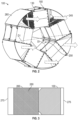
FIG. 1 shows a heat exchanger according to a disclosed embodiment; -
FIG. 2 is an aft view of the heat exchanger ofFIG. 1 ; -
FIG. 3 shows an engine that includes the heat exchanger ofFIG. 1 ; -
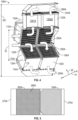
FIG. 4 shows a heat exchanger according to another disclosed embodiment; and -
FIG. 5 shows an engine that includes the heat exchanger ofFIG. 4 . - The embodiments disclosed herein are directed to a configuration of a heat exchanger. The arrangement of the embodiments utilize an annular compact packaging configuration for the heat exchangers that provides a large flow-facing surface area, reducing pressure losses. The heat exchanger can be used with any heat producing device. For example, it can be used in an exhaust of an aircraft engine. In one embodiment, when used with a turbofan engine, for example, it can improve efficiency by harvesting waste heat from the exhaust stream while providing a low pressure drop.
- Turning to
FIG. 1 , aheat exchanger 100 is shown. Theheat exchanger 100 includes afront end 110 and anaft end 120 spaced apart from each other. Flow (e.g., the arrows inFIG. 1 ) moves from thefront end 110 to theaft end 120. Theheat exchanger 100 includesheat exchanger cores 130 circumferentially spaced apart from each other in anannular loop 140 such that they definecircumferential gaps 150 between adjacent pairs of thecores 130. Thecores 130 are counter-flow heat exchangers that are rectangular shaped and havecases 160 that includeaxial front surfaces 170 andaxial aft surfaces 180. Cross flow heat exchangers are within the scope of the embodiments. Thecores 130 are arranged inpairs axial direction 10 as show inFIG. 1 , though this is not intended on limiting the scope of the core arrangements. Thecores 130 have inlet andoutlet headers exterior sides 172, e.g., relative to theradial direction 20 in a non-limiting embodiment.Fluid flow 175 through the core via the headers is used to recapture waste heat from an engine flow. - The
cores 130, configured as axially aligned in sets orpairs front end 110 to theaft end 120. Eachcore 130 has a circumferentially facinginlet side 190 and a circumferentially facingoutlet side 200. Within thecircumferential gaps 150, theinlet sides 190 and theoutlet sides 200 from the adjacent pairs of thecores 130 face into the same ones of thecircumferential gaps 150, e.g., they are juxtaposed. - An
annular inlet duct 210 extends axially forward from thefront end 110 of theheat exchanger 100 to afront end 215 of theinlet duct 210. Theheat exchanger 100 has a first outer diameter D1 (FIG. 2 ). Theinlet duct 210 tapers toward thefront end 215 of theinlet duct 210 to a second outer diameter D2 that is smaller than the first outer diameter D 1. -
Core guide vanes 220, which can be implemented as smooth or tapered walls, are disposed in thecircumferential gaps 150. The core guide vanes 220 include anaft portion 230 that extends from theaft end 120 of theheat exchanger 100 to thefront end 110 of theheat exchanger 100. Aforward portion 235 of thecore guide vanes 220 extends from thefront end 110 of theheat exchanger 100 to thefront end 215 of theinlet duct 210. - At the
front end 110 of theheat exchanger 100, the core guide vanes 220 are closer to theoutlet side 200 of thecores 130. At theaft end 120 theheat exchanger 100, the core guide vanes 220 are closer to theinlet sides 190 of thecores 130. From this configuration, thecore guide vanes 220 are configured to turn aflow 245 from an axial direction toward theinlet sides 190 of thecores 130 and from theoutlet sides 200 of thecores 130 toward the axial direction. - Duct guide vanes 240 extend axially forward from the
inlet sides 190 of thecores 130 to an adjacent one of thecore guide vanes 220, e.g., to theforward portion 235 of thecore guide vanes 220. The duct guide vanes 240 connect over the axialfront surfaces 170 of thecores 130. This configuration forms a flow path around thefront surfaces 170 of thecores 130. - As shown in
FIG. 2 , acenter flow passageway 250 is defined between thecores 130. Specifically, theheat exchanger 100 has a radial center RC. Thecases 160 of thecores 130 have radial outer surfaces RO located at the first outer diameter D1 of theheat exchanger 100 and radial inner surfaces RI that are spaced apart from the radial center RO of theheat exchanger 100. Thecenter flow passageway 250 is defined by the radial inner surfaces RI of thecores 130. That is, an inner diameter DI of theheat exchanger 100 formed by the radially inner facing surfaces of thecores 130 defines the diameter of thecenter flow passageway 250. Shroudsections 260 extend between thecores 130. Theshroud sections 260 define a radial flow boundary for thegas flow 245 around thecircumferential gaps 150. In the illustrated embodiment, there is no air-flow through the center region. However, in certain embodiments, a bypass flow could be provided though the center region rather than sending the entirety of the airflow through the cores. - Turning to
FIG. 3 , agas turbine engine 265 is shown. Theengine 265 has anengine inlet 270, anengine core 280 located aft of theengine inlet 270 and anexhaust duct 275 located aft of theengine core 280. Theheat exchanger 100 is disposed between theengine core 280 and theexhaust duct 275 in one embodiment. - With the above embodiments, rectangular
heat exchanger cores 130 are packaged in an annular loop configuration. Exhaust flow enters axially, turns approximately ninety degrees to circumferentially flow through theheat exchanger cores 130, then turns back in to substantially the original flow direction to continue axially. Space orgaps 150 between theheat exchanger cores 130 is utilized to duct the flow into and out of the heat exchangers.Core guide vanes 220 between adjacentheat exchanger cores 130 helps to provide uniform flow to theheat exchanger cores 130. - Turning to
FIG. 4 , another embodiment of theheat exchanger 100A is shown. Theheat exchanger 100A includes afront end 110A and anaft end 120A spaced apart from each other. Theheat exchanger 100A defines radial center RC and an outer diameter DO.Heat exchanger cores 130A, configured as axially aligned in sets or pairs 1301A, 1302A extend from thefront end 110A to theaft end 120A and are disposed in an annular loop 140A. Thecores 130A have inlet andoutlet headers front surface 170A, in a non-limiting embodiment. Flow (e.g., the arrows inFIG. 4 ) moves from thefront end 110A to theaft end 120A.Fluid 175 through the core via the headers is used to recapture waste heat from an engine flow. - The
cores 130A are arranged inpairs axial direction 10, though this is not intended on limiting the scope of the core arrangements. Thecores 130A each have aninlet side 190A facing radially inward, relative to theradial direction 20, toward the radial center RC of theheat exchanger 100A and anoutlet side 200A facing radially outward, toward the outer diameter DO of theheat exchanger 100A. Thecores 130A are circumferentially spaced apart from each other to definecircumferential gaps 150A between adjacent pairs ofcores 130A. - A center flow passageway 250A is defined between the
cores 130A. Specifically, the inlet sides 190A of thecores 130A are spaced apart from the radial center RC of theheat exchanger 100A to define a radial inner surface RI of theheat exchanger 100A. This spacing defines the center flow passageway 250A. That is, an inner diameter DI of theheat exchanger 100A formed by the radially inner facing surfaces of thecores 130A defines the diameter of the center flow passageway 250A. - A
guide plate 290A is located at theaft end 120A of theheat exchanger 100A and within the center flow passageway 250A. Theguide plate 290A forms a V-shape with apeak 295A of the shape directed toward thefront end 110A of theheat exchanger 100A. From this configuration, theguide plate 290A is configured to turn theflow 245A from the axial direction to the radial direction and guide theflow 245A to the inlet sides 190A of thecores 130A. -
Shroud sections 260A are disposed radially exterior to thecores 130A, and are spaced apart from thegaps 150A to not enclose thegaps 150A in this embodiment, and define the outer diameter DO of theheat exchanger 100A. Theshroud sections 260A are partially cup-shaped to form an outer boundary or guide that is configured to turn aflow 245A from a radial direction at the outlet sides of thecores 130A to an axial direction. - As shown in
FIG. 5 , agas turbine engine 265A includes anengine inlet 270A, anengine core 280A located aft of theengine inlet 270A, and anexhaust duct 275A located aft of theengine core 280A. Theheat exchanger 100A shown inFIG. 4 is disposed between theengine core 280A and theexhaust duct 275A in one embodiment. - In the configuration of
FIGS. 4 and 5 , the faces of thecores 130A are directed toward the inner and outer diameters DI, DO of the heat exchanger configuration. Theexhaust flow 245A in this configuration flows radially through theheat exchanger cores 130A. - These embodiments provide packaging configuration for
heat exchangers engine heat exchanger cores heat exchanger cores heat exchanger cores - The terminology used herein is for the purpose of describing particular embodiments only and is not intended to be limiting of the present disclosure. As used herein, the singular forms "a", "an" and "the" are intended to include the plural forms as well, unless the context clearly indicates otherwise. It will be further understood that the terms "comprises" and/or "comprising," when used in this specification, specify the presence of stated features, integers, steps, operations, elements, and/or components, but do not preclude the presence or addition of one or more other features, integers, steps, operations, element components, and/or groups thereof.
- Those of skill in the art will appreciate that various example embodiments are shown and described herein, each having certain features in the particular embodiments, but the present disclosure is not thus limited. Rather, the present disclosure can be modified to incorporate any number of variations within the scope of the present invention as defined by the claims. Additionally, while various embodiments of the present disclosure have been described, it is to be understood that aspects of the present disclosure may include only some of the described embodiments. Accordingly, the present disclosure is not to be seen as limited by the foregoing description, but is only limited by the scope of the appended claims.
Claims (14)
- A heat exchanger comprising:a front end (110) and an aft end (120) spaced apart from each other;heat exchanger cores (130) that are circumferentially spaced apart from each other in an annular loop (140) such that they define circumferential gaps (150) between adjacent pairs of the cores;wherein the cores, configured individually or as axially aligned sets, extend from the front end to the aft end and have circumferentially facing inlet sides (190) and circumferentially facing outlet sides (200) configured such that the inlet sides and the outlet sides from the adjacent pairs of the cores face into the same ones of the circumferential gaps; andcore guide vanes (220) disposed in the circumferential gaps;the core guide vanes have an aft portion (230) that extends from the front end to the aft end of the heat exchanger;wherein: at the front end the heat exchanger, the core guide vanes are closer to the outlet side of the cores; and at the aft end the heat exchanger, the core guide vanes are closer to the inlet sides of the cores;whereby the core guide vanes are configured to turn a gas flow (245) from an axial direction toward the inlet sides of the cores and from the outlet sides of the cores toward the axial direction.
- The heat exchanger of claim 1, wherein:
the cores are counter-flow or cross flow heat exchangers. - The heat exchanger of claim 1 or 2, wherein:the cores are rectangular shaped and have cases (160) that include axial front surfaces;the core guide vanes each include a forward portion (235) that extends forward from the aft portion; andthe heat exchanger further comprises:an annular inlet duct (210) extending axially forward from the front end of the heat exchanger to a front end of the inlet duct, wherein the forward portion of the core guide vanes extends to the front end of the inlet duct; andduct guide vanes (240) that extend axially forward from the inlet sides of the cores to an adjacent one of the core guide vanes, and connect over the axial front surfaces of the cores, to thereby form a flow path around the front surfaces of the cores.
- The heat exchanger of claim 3, wherein the heat exchanger has a first outer diameter, the inlet duct tapers toward the front end of the inlet duct to a second outer diameter that is smaller than the first outer diameter.
- The heat exchanger of claim 4, wherein:the heat exchanger has a radial center; andthe cases of the cores have radial outer surfaces located at the first outer diameter of the heat exchanger and radial inner surfaces that are spaced apart from the radial center of the heat exchanger, to thereby define a center flow passageway between the cores.
- The heat exchanger of any preceding claim, further comprising:
shroud sections (260) extending between the cores, to define a radial flow boundary around the circumferential gaps. - A gas turbine engine comprising:an engine inlet (270);an engine core (280) located aft of the inlet;an exhaust duct (275) located aft of the engine core; andthe heat exchanger (100) of any preceding claim disposed between the engine core and the exhaust duct.
- A heat exchanger, comprisinga front end (110A) and an aft end (120A) spaced apart from each other, and the heat exchanger defining radial center and outer diameter;heat exchanger cores (130A) extending from the front end to the aft end and are disposed in an annular loop;wherein the cores have inlet sides (190A) facing radially inward, toward the radial center of the heat exchanger and outlet sides (200A) facing radially outward, toward the outer diameter of the heat exchanger.
- The heat exchanger of claim 8, wherein:
the cores are counter-flow or cross flow heat exchangers. - The heat exchanger of claim 8 or 9, wherein: the cores are rectangular shaped.
- The heat exchanger of claim 8, 9 or 10, comprising:
shroud sections (260A) disposed radially exterior to the cores to define the outer diameter of the heat exchanger, the shroud sections being configured to turn a gas flow (245A) from a radial direction at the outlet sides of the cores to an axial direction. - The heat exchanger of claim 11, wherein:
the inlet sides of the cores are spaced apart from the radial center of the heat exchanger to define a center flow passageway between the cores. - The heat exchanger of claim 12, comprising:
a guide plate (290A) located at the aft end of the heat exchanger and within the center flow passageway, the guide plate forming a V shape with a peak (295A) directed toward the front end of the heat exchanger, whereby the guide plate is configured to turn the gas flow from the axial direction to the radial direction and guide the gas flow to the inlet sides of the cores. - A gas turbine engine comprising:an engine inlet (270A);an engine core (280A) located aft of the inlet;an exhaust duct (275A) located aft of the engine core; andthe heat exchanger (100A) of any of claims 8 to 13 disposed between the engine core and the exhaust duct.
Applications Claiming Priority (1)
| Application Number | Priority Date | Filing Date | Title |
|---|---|---|---|
| US17/947,337 US12228342B2 (en) | 2022-09-19 | 2022-09-19 | Annular arrangement of heat exchangers |
Publications (2)
| Publication Number | Publication Date |
|---|---|
| EP4343262A1 true EP4343262A1 (en) | 2024-03-27 |
| EP4343262B1 EP4343262B1 (en) | 2026-04-15 |
Family
ID=87517359
Family Applications (1)
| Application Number | Title | Priority Date | Filing Date |
|---|---|---|---|
| EP23187638.4A Active EP4343262B1 (en) | 2022-09-19 | 2023-07-25 | Annular arrangement of heat exchangers |
Country Status (2)
| Country | Link |
|---|---|
| US (1) | US12228342B2 (en) |
| EP (1) | EP4343262B1 (en) |
Citations (7)
| Publication number | Priority date | Publication date | Assignee | Title |
|---|---|---|---|---|
| US3228464A (en) * | 1963-08-09 | 1966-01-11 | Avco Corp | Corrugated plate counter flow heat exchanger |
| US3818984A (en) * | 1972-01-31 | 1974-06-25 | Nippon Denso Co | Heat exchanger |
| US4993223A (en) * | 1989-09-11 | 1991-02-19 | Allied-Signal Inc. | Annular recuperator |
| US5004044A (en) * | 1989-10-02 | 1991-04-02 | Avco Corporation | Compact rectilinear heat exhanger |
| AR001342A1 (en) | 1995-01-20 | 1997-10-22 | E K M A Inc | Method for preparing a culture of microorganisms, culture thus prepared, composition that stimulates vegetl growth comprising said culture, formulation of nutrients that integrates said composition and method for stimulating the growth of a plant administering said composition. |
| US20120216544A1 (en) * | 2011-02-28 | 2012-08-30 | Andreas Eleftheriou | Swirl reducing gas turbine engine recuperator |
| US20160305324A1 (en) * | 2013-12-05 | 2016-10-20 | United Technologies Corporation | Gas turbine engines with intercoolers and recuperators |
Family Cites Families (11)
| Publication number | Priority date | Publication date | Assignee | Title |
|---|---|---|---|---|
| US4582126A (en) | 1984-05-01 | 1986-04-15 | Mechanical Technology Incorporated | Heat exchanger with ceramic elements |
| US9513059B2 (en) * | 2011-02-04 | 2016-12-06 | Lockheed Martin Corporation | Radial-flow heat exchanger with foam heat exchange fins |
| US9394828B2 (en) * | 2011-02-28 | 2016-07-19 | Pratt & Whitney Canada Corp. | Gas turbine engine recuperator with floating connection |
| WO2013147953A1 (en) * | 2011-12-30 | 2013-10-03 | Rolls-Royce North American Technologies Inc. | Aircraft propulsion gas turbine engine with heat exchange |
| EP2951419B1 (en) | 2013-01-29 | 2018-09-05 | United Technologies Corporation | Gas turbine engine with lower bifurcation heat exchanger |
| US10563582B2 (en) | 2016-01-19 | 2020-02-18 | United Technologies Corporation | Heat exchanger array |
| DE102017208324A1 (en) | 2017-05-17 | 2018-11-22 | Mahle International Gmbh | Heat exchanger |
| US11378009B2 (en) * | 2019-05-15 | 2022-07-05 | Raytheon Technologies Corporation | Multi-mode heat rejection system for a gas turbine engine |
| CA3162414A1 (en) * | 2019-12-23 | 2021-07-01 | Kent E. Wardle | Molten fuel reactors and orifice ring plates for molten fuel reactors |
| US11650018B2 (en) | 2020-02-07 | 2023-05-16 | Raytheon Technologies Corporation | Duct mounted heat exchanger |
| GB2599692A (en) | 2020-10-09 | 2022-04-13 | Rolls Royce Plc | A heat exchanger |
-
2022
- 2022-09-19 US US17/947,337 patent/US12228342B2/en active Active
-
2023
- 2023-07-25 EP EP23187638.4A patent/EP4343262B1/en active Active
Patent Citations (7)
| Publication number | Priority date | Publication date | Assignee | Title |
|---|---|---|---|---|
| US3228464A (en) * | 1963-08-09 | 1966-01-11 | Avco Corp | Corrugated plate counter flow heat exchanger |
| US3818984A (en) * | 1972-01-31 | 1974-06-25 | Nippon Denso Co | Heat exchanger |
| US4993223A (en) * | 1989-09-11 | 1991-02-19 | Allied-Signal Inc. | Annular recuperator |
| US5004044A (en) * | 1989-10-02 | 1991-04-02 | Avco Corporation | Compact rectilinear heat exhanger |
| AR001342A1 (en) | 1995-01-20 | 1997-10-22 | E K M A Inc | Method for preparing a culture of microorganisms, culture thus prepared, composition that stimulates vegetl growth comprising said culture, formulation of nutrients that integrates said composition and method for stimulating the growth of a plant administering said composition. |
| US20120216544A1 (en) * | 2011-02-28 | 2012-08-30 | Andreas Eleftheriou | Swirl reducing gas turbine engine recuperator |
| US20160305324A1 (en) * | 2013-12-05 | 2016-10-20 | United Technologies Corporation | Gas turbine engines with intercoolers and recuperators |
Also Published As
| Publication number | Publication date |
|---|---|
| EP4343262B1 (en) | 2026-04-15 |
| US12228342B2 (en) | 2025-02-18 |
| US20240093943A1 (en) | 2024-03-21 |
Similar Documents
| Publication | Publication Date | Title |
|---|---|---|
| KR102348770B1 (en) | Contoured wall heat exchanger | |
| US11125160B2 (en) | Method and system for combination heat exchanger | |
| EP3336311B1 (en) | Turbomachine blade with trailing edge cooling circuit | |
| EP3911908B1 (en) | Aircraft heat exchanger | |
| EP0695874B1 (en) | A gas turbine engine and a diffuser therefor | |
| EP3118417A1 (en) | Shroud assembly for gas turbine engine | |
| EP2944794A1 (en) | Fan by-pass duct for intercooled turbo fan engines | |
| CN107989660B (en) | Partially clad trailing edge cooling circuit with pressure side impingement | |
| EP3196443A1 (en) | Heat exchanger array | |
| US20240240589A1 (en) | Particle separators for turbomachines and method of operating the same | |
| CN105339591A (en) | Nozzle film cooling with alternating compound angles | |
| EP4343262B1 (en) | Annular arrangement of heat exchangers | |
| US20160208926A1 (en) | Splined honeycomb seals | |
| EP4644815A1 (en) | Heat exchanger having a mixing chamber and protrusions | |
| EP4644816A1 (en) | Heat exchanger having a mixing chamber with louvers | |
| EP4644680A1 (en) | Heat exchanger having a mixing chamber with fins | |
| US20250334357A1 (en) | Heat exchanger having a mixing chamber with convergent section |
Legal Events
| Date | Code | Title | Description |
|---|---|---|---|
| PUAI | Public reference made under article 153(3) epc to a published international application that has entered the european phase |
Free format text: ORIGINAL CODE: 0009012 |
|
| STAA | Information on the status of an ep patent application or granted ep patent |
Free format text: STATUS: THE APPLICATION HAS BEEN PUBLISHED |
|
| AK | Designated contracting states |
Kind code of ref document: A1 Designated state(s): AL AT BE BG CH CY CZ DE DK EE ES FI FR GB GR HR HU IE IS IT LI LT LU LV MC ME MK MT NL NO PL PT RO RS SE SI SK SM TR |
|
| STAA | Information on the status of an ep patent application or granted ep patent |
Free format text: STATUS: REQUEST FOR EXAMINATION WAS MADE |
|
| 17P | Request for examination filed |
Effective date: 20240926 |
|
| RBV | Designated contracting states (corrected) |
Designated state(s): AL AT BE BG CH CY CZ DE DK EE ES FI FR GB GR HR HU IE IS IT LI LT LU LV MC ME MK MT NL NO PL PT RO RS SE SI SK SM TR |
|
| RIC1 | Information provided on ipc code assigned before grant |
Ipc: F28D 21/00 20060101AFI20251127BHEP Ipc: F02C 7/00 20060101ALI20251127BHEP |
|
| GRAP | Despatch of communication of intention to grant a patent |
Free format text: ORIGINAL CODE: EPIDOSNIGR1 |
|
| STAA | Information on the status of an ep patent application or granted ep patent |
Free format text: STATUS: GRANT OF PATENT IS INTENDED |
|
| INTG | Intention to grant announced |
Effective date: 20260112 |
|
| GRAS | Grant fee paid |
Free format text: ORIGINAL CODE: EPIDOSNIGR3 |
|
| GRAA | (expected) grant |
Free format text: ORIGINAL CODE: 0009210 |
|
| STAA | Information on the status of an ep patent application or granted ep patent |
Free format text: STATUS: THE PATENT HAS BEEN GRANTED |
|
| AK | Designated contracting states |
Kind code of ref document: B1 Designated state(s): AL AT BE BG CH CY CZ DE DK EE ES FI FR GB GR HR HU IE IS IT LI LT LU LV MC ME MK MT NL NO PL PT RO RS SE SI SK SM TR |
|
| REG | Reference to a national code |
Ref country code: CH Ref legal event code: F10 Free format text: ST27 STATUS EVENT CODE: U-0-0-F10-F00 (AS PROVIDED BY THE NATIONAL OFFICE) Effective date: 20260415 |
|
| REG | Reference to a national code |
Ref country code: DE Ref legal event code: R096 Ref document number: 602023015187 Country of ref document: DE |