EP4343195A1 - Support assembly and display apparatus - Google Patents
Support assembly and display apparatus Download PDFInfo
- Publication number
- EP4343195A1 EP4343195A1 EP22941494.1A EP22941494A EP4343195A1 EP 4343195 A1 EP4343195 A1 EP 4343195A1 EP 22941494 A EP22941494 A EP 22941494A EP 4343195 A1 EP4343195 A1 EP 4343195A1
- Authority
- EP
- European Patent Office
- Prior art keywords
- support member
- support
- body mechanism
- flexible screen
- sliding direction
- Prior art date
- Legal status (The legal status is an assumption and is not a legal conclusion. Google has not performed a legal analysis and makes no representation as to the accuracy of the status listed.)
- Pending
Links
Images



Classifications
-
- H—ELECTRICITY
- H10—SEMICONDUCTOR DEVICES; ELECTRIC SOLID-STATE DEVICES NOT OTHERWISE PROVIDED FOR
- H10K—ORGANIC ELECTRIC SOLID-STATE DEVICES
- H10K59/00—Integrated devices, or assemblies of multiple devices, comprising at least one organic light-emitting element covered by group H10K50/00
- H10K59/80—Constructional details
- H10K59/87—Passivation; Containers; Encapsulations
-
- H—ELECTRICITY
- H05—ELECTRIC TECHNIQUES NOT OTHERWISE PROVIDED FOR
- H05K—PRINTED CIRCUITS; CASINGS OR CONSTRUCTIONAL DETAILS OF ELECTRIC APPARATUS; MANUFACTURE OF ASSEMBLAGES OF ELECTRICAL COMPONENTS
- H05K5/00—Casings, cabinets or drawers for electric apparatus
- H05K5/02—Details
- H05K5/0217—Mechanical details of casings
-
- F—MECHANICAL ENGINEERING; LIGHTING; HEATING; WEAPONS; BLASTING
- F16—ENGINEERING ELEMENTS AND UNITS; GENERAL MEASURES FOR PRODUCING AND MAINTAINING EFFECTIVE FUNCTIONING OF MACHINES OR INSTALLATIONS; THERMAL INSULATION IN GENERAL
- F16M—FRAMES, CASINGS OR BEDS OF ENGINES, MACHINES OR APPARATUS, NOT SPECIFIC TO ENGINES, MACHINES OR APPARATUS PROVIDED FOR ELSEWHERE; STANDS; SUPPORTS
- F16M11/00—Stands or trestles as supports for apparatus or articles placed thereon ; Stands for scientific apparatus such as gravitational force meters
- F16M11/02—Heads
- F16M11/04—Means for attachment of apparatus; Means allowing adjustment of the apparatus relatively to the stand
- F16M11/043—Allowing translations
- F16M11/045—Allowing translations adapted to left-right translation movement
-
- B—PERFORMING OPERATIONS; TRANSPORTING
- B65—CONVEYING; PACKING; STORING; HANDLING THIN OR FILAMENTARY MATERIAL
- B65H—HANDLING THIN OR FILAMENTARY MATERIAL, e.g. SHEETS, WEBS, CABLES
- B65H75/00—Storing webs, tapes, or filamentary material, e.g. on reels
- B65H75/02—Cores, formers, supports, or holders for coiled, wound, or folded material, e.g. reels, spindles, bobbins, cop tubes, cans, mandrels or chucks
- B65H75/34—Cores, formers, supports, or holders for coiled, wound, or folded material, e.g. reels, spindles, bobbins, cop tubes, cans, mandrels or chucks specially adapted or mounted for storing and repeatedly paying-out and re-storing lengths of material provided for particular purposes, e.g. anchored hoses, power cables
- B65H75/38—Cores, formers, supports, or holders for coiled, wound, or folded material, e.g. reels, spindles, bobbins, cop tubes, cans, mandrels or chucks specially adapted or mounted for storing and repeatedly paying-out and re-storing lengths of material provided for particular purposes, e.g. anchored hoses, power cables involving the use of a core or former internal to, and supporting, a stored package of material
- B65H75/44—Constructional details
-
- F—MECHANICAL ENGINEERING; LIGHTING; HEATING; WEAPONS; BLASTING
- F16—ENGINEERING ELEMENTS AND UNITS; GENERAL MEASURES FOR PRODUCING AND MAINTAINING EFFECTIVE FUNCTIONING OF MACHINES OR INSTALLATIONS; THERMAL INSULATION IN GENERAL
- F16M—FRAMES, CASINGS OR BEDS OF ENGINES, MACHINES OR APPARATUS, NOT SPECIFIC TO ENGINES, MACHINES OR APPARATUS PROVIDED FOR ELSEWHERE; STANDS; SUPPORTS
- F16M13/00—Other supports for positioning apparatus or articles; Means for steadying hand-held apparatus or articles
-
- G—PHYSICS
- G06—COMPUTING OR CALCULATING; COUNTING
- G06F—ELECTRIC DIGITAL DATA PROCESSING
- G06F1/00—Details not covered by groups G06F3/00 - G06F13/00 and G06F21/00
- G06F1/16—Constructional details or arrangements
-
- G—PHYSICS
- G06—COMPUTING OR CALCULATING; COUNTING
- G06F—ELECTRIC DIGITAL DATA PROCESSING
- G06F1/00—Details not covered by groups G06F3/00 - G06F13/00 and G06F21/00
- G06F1/16—Constructional details or arrangements
- G06F1/1613—Constructional details or arrangements for portable computers
- G06F1/1633—Constructional details or arrangements of portable computers not specific to the type of enclosures covered by groups G06F1/1615 - G06F1/1626
- G06F1/1637—Details related to the display arrangement, including those related to the mounting of the display in the housing
- G06F1/1641—Details related to the display arrangement, including those related to the mounting of the display in the housing the display being formed by a plurality of foldable display components
-
- G—PHYSICS
- G06—COMPUTING OR CALCULATING; COUNTING
- G06F—ELECTRIC DIGITAL DATA PROCESSING
- G06F1/00—Details not covered by groups G06F3/00 - G06F13/00 and G06F21/00
- G06F1/16—Constructional details or arrangements
- G06F1/1613—Constructional details or arrangements for portable computers
- G06F1/1633—Constructional details or arrangements of portable computers not specific to the type of enclosures covered by groups G06F1/1615 - G06F1/1626
- G06F1/1637—Details related to the display arrangement, including those related to the mounting of the display in the housing
- G06F1/1652—Details related to the display arrangement, including those related to the mounting of the display in the housing the display being flexible, e.g. mimicking a sheet of paper, or rollable
-
- G—PHYSICS
- G09—EDUCATION; CRYPTOGRAPHY; DISPLAY; ADVERTISING; SEALS
- G09F—DISPLAYING; ADVERTISING; SIGNS; LABELS OR NAME-PLATES; SEALS
- G09F9/00—Indicating arrangements for variable information in which the information is built-up on a support by selection or combination of individual elements
- G09F9/30—Indicating arrangements for variable information in which the information is built-up on a support by selection or combination of individual elements in which the desired character or characters are formed by combining individual elements
-
- G—PHYSICS
- G09—EDUCATION; CRYPTOGRAPHY; DISPLAY; ADVERTISING; SEALS
- G09F—DISPLAYING; ADVERTISING; SIGNS; LABELS OR NAME-PLATES; SEALS
- G09F9/00—Indicating arrangements for variable information in which the information is built-up on a support by selection or combination of individual elements
- G09F9/30—Indicating arrangements for variable information in which the information is built-up on a support by selection or combination of individual elements in which the desired character or characters are formed by combining individual elements
- G09F9/301—Indicating arrangements for variable information in which the information is built-up on a support by selection or combination of individual elements in which the desired character or characters are formed by combining individual elements flexible foldable or roll-able electronic displays, e.g. thin LCD, OLED
-
- H—ELECTRICITY
- H04—ELECTRIC COMMUNICATION TECHNIQUE
- H04M—TELEPHONIC COMMUNICATION
- H04M1/00—Substation equipment, e.g. for use by subscribers
- H04M1/02—Constructional features of telephone sets
- H04M1/0202—Portable telephone sets, e.g. cordless phones, mobile phones or bar type handsets
- H04M1/0206—Portable telephones comprising a plurality of mechanically joined movable body parts, e.g. hinged housings
- H04M1/0208—Portable telephones comprising a plurality of mechanically joined movable body parts, e.g. hinged housings characterized by the relative motions of the body parts
- H04M1/0235—Slidable or telescopic telephones, i.e. with a relative translation movement of the body parts; Telephones using a combination of translation and other relative motions of the body parts
-
- H—ELECTRICITY
- H04—ELECTRIC COMMUNICATION TECHNIQUE
- H04M—TELEPHONIC COMMUNICATION
- H04M1/00—Substation equipment, e.g. for use by subscribers
- H04M1/02—Constructional features of telephone sets
- H04M1/0202—Portable telephone sets, e.g. cordless phones, mobile phones or bar type handsets
- H04M1/026—Details of the structure or mounting of specific components
- H04M1/0266—Details of the structure or mounting of specific components for a display module assembly
- H04M1/0268—Details of the structure or mounting of specific components for a display module assembly including a flexible display panel
-
- H—ELECTRICITY
- H10—SEMICONDUCTOR DEVICES; ELECTRIC SOLID-STATE DEVICES NOT OTHERWISE PROVIDED FOR
- H10K—ORGANIC ELECTRIC SOLID-STATE DEVICES
- H10K77/00—Constructional details of devices covered by this subclass and not covered by groups H10K10/80, H10K30/80, H10K50/80 or H10K59/80
- H10K77/10—Substrates, e.g. flexible substrates
- H10K77/111—Flexible substrates
-
- B—PERFORMING OPERATIONS; TRANSPORTING
- B65—CONVEYING; PACKING; STORING; HANDLING THIN OR FILAMENTARY MATERIAL
- B65H—HANDLING THIN OR FILAMENTARY MATERIAL, e.g. SHEETS, WEBS, CABLES
- B65H2701/00—Handled material; Storage means
- B65H2701/10—Handled articles or webs
- B65H2701/19—Specific article or web
Definitions
- the present disclosure relates to the technical field of display, and in particular to a support assembly and a display device.
- a support assembly is generally disposed below the unfolded flexible screen. How to reduce a volume of the support assembly has become a research hotspot.
- the present disclosure provides a support assembly and a display device.
- the support assembly may provide more effective support for an unfolded flexible screen, and reduce a volume of a first support member after rolling the first support member.
- the support assembly includes a body mechanism and a first support member.
- a first surface of the body mechanism is configured to support a part of the flexible screen.
- At least a part of the first support member is located an outer side of the body mechanism, disposed side by side with the body mechanism, and configured to support another part of the flexible screen which extends out of the first surface.
- the first support member includes a first end and a second end disposed along a length direction of the first support member. The first end is fixed relative to the body mechanism, and the second end is configured to slide along a direction close to or away from the body mechanism. In a sliding direction, the first support member includes a plurality of flexible members disposed side by side, and two adjacent of the plurality of flexible members are connected to each other to form a netlike structure.
- the display device includes a flexible screen and the support assembly described above, and the support assembly is configured to support the flexible screen.
- the support assembly provided in the present disclosure is configured to support the flexible screen.
- the support assembly includes the body mechanism and the first support member.
- the first surface of the body mechanism is configured to support a part of the flexible screen.
- the first support member is configured to support another part of the flexible screen which extends out of the first surface.
- the first support member is configured to provide strong support for the flexible screen, especially when users touch the flexible screen.
- the first support member In a sliding direction of the first support member, the first support member includes multiple flexible members disposed side by side, and two adjacent flexible members are connected to each other to form a netlike structure. This design mode may improve the flexibility of the first support member in the sliding direction.
- the first support member may be rolled with a smaller radius in the sliding direction, to reduce a volume occupied by the first support member, which facilitates to make the display device light and thin.
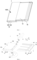
- FIG. 1 is a structural schematic view of a support assembly in some embodiments of the present disclosure
- FIG. 2 is an exploded schematic view of the support assembly of FIG. 1 in some embodiments of the present disclosure
- a support assembly 1 is configured to support a flexible screen.
- the flexible screen may be a flexible OLED (Organic Light Emitting Diode) screen, a flexible Micro LED screen, or the like.
- the support assembly 1 includes a body mechanism 10 and a first support member 12.
- the body mechanism 10 includes a first surface 1000, and the first surface 1000 is configured to support a part of a flexible screen. In some embodiments, the first surface 1000 is also configured to fix the part of the flexible screen through an adhesive element or the like. At least a part of the first support member 12 is located on an outer side of the body mechanism 10 and arranged side by side with the body mechanism 10, to support the flexible screen extending out of the first surface 1000.
- the first support member 12 includes a first end 121 and a second end 123, and the first end 121 and the second end 123 are disposed along a length direction of the first support member 12. The first end 121 and the second end 123 respectively refer to two opposite ends along the length direction when the first support member 12 is fully unfolded.
- the first end 121 is fixed relative to the body mechanism 10, and the second end 123 may slide in a direction close to or away from the body mechanism 10, to change a size of a support surface formed by the first support member 12 and the body mechanism 10.
- the first support member 12 includes multiple flexible members 120 disposed side by side in a sliding direction X, and adjacent flexible members 120 are connected to each other to form a netlike structure. This design mode may improve flexibility of the first support member 12 in the sliding direction X.
- shapes of holes of the netlike structure may be approximated as a quadrilateral, such as a rhombus, etc.
- the first support member 12 is configured to support the flexible screen that extends out of the first surface 1000, thereby providing strong support for the flexible screen, especially when users touch the flexible screen.
- the first support member 12 includes multiple flexible members 120 arranged side by side or in parallel, and adjacent flexible members 120 are connected to each other to form the netlike structure.
- This design mode may improve the flexibility of the first support member 12 in the sliding direction X.
- the first support member 12 may be rolled with a smaller radius in the sliding direction, to reduce a volume occupied by the first support member 12, which facilitates to make the display device light and thin.
- the support assembly 1 provided in some embodiments of the present disclosure further includes a second support member 16.
- the second support member 16 has a certain degree of rigidity, and the flexibility of the second support member 16 is less than that of the first support member 12.
- the second support member 16 is stacked on a side of the first support member 12 away from the flexible screen 2 when the first support member 12 supports the flexible screen 2.
- FIG. 3 is a structural schematic view illustrating a part of the support assembly of FIG. 1 and a flexible screen in some embodiments of the present disclosure.
- the body mechanism 10 is configured to support the flexible screen 2 located on the first surface 1000 of the body mechanism 10.
- the remaining part of the flexible screen 2 located on the outer side of the body mechanism 10 is supported by the first support member 12 and the second support member 16 that are stacked on each other during unfolding the remaining part of the flexible screen 2.
- the first support member 12 with a certain degree of flexibility may better fit with or be better attached to the flexible screen 2, and the second support member 16 with a certain degree of rigidity may compensate for the strength of the first support member 12.
- the first support member 12 and the second support member 16 may provide strong support for the flexible screen 2, especially when the users touch the flexible screen 2.
- the second support member 16 is slidably connected to the body mechanism 10.
- a sliding direction X of the second end 123 relative to the body mechanism 10 is the same as a sliding direction X of the second support member 16 relative to the body mechanism 10.
- This design mode may allow the first support member 12 and the second support member 14 to synchronously translate, to provide synchronous support for an unfolded flexible screen, thereby achieving a better support effect.
- the second end 123 and the second support member 16 simultaneously approach or move away from the body mechanism 10 along the sliding direction X.
- This design mode allows the support assembly 1 to have a relatively simple structure.
- the support assembly 1 provided in the present disclosure also includes a translation mechanism 18, and the translation mechanism 18 is slidably connected to the body mechanism 10.
- the second support member 16 includes a fixed end 164, and the second end 123 of the first support member 12 and the fixed end 164 are fixed relative to the translation mechanism 18.
- the translation mechanism 18 may synchronously drive the second support member 16 and the second end 123 to slide relative to the body mechanism 10, in order to reduce the difficulty of sliding the second support member 16 and the second end 123 relative to the body mechanism 10.
- the support assembly 1 provided in the present disclosure also includes a rolling shaft 14, and the rolling shaft 14 is configured to roll the first support member 12.
- One of the first end 121 and the second end 123 is fixedly connected to the rolling shaft 14.
- the rolling shaft 14 may make the process of rolling and unfolding the first support member 12 relatively simple.
- the rolling shaft 14 may approach or move away from the body mechanism 10 along the sliding direction X, driving the first support member 12 to roll or unfold.
- the rolling shaft 14 may be located on the outer side of the body mechanism 10. In some embodiments, the rolling shaft 14 may be disposed side by side with the body mechanism 10 in the sliding direction X where the rolling shaft 14 slides relative to the body mechanism 10.
- the first end 121 of the first support member 12 is fixed on the body mechanism 10, and the second end 123 of the first support member 12 is fixed on the rolling shaft 14.
- the rolling shaft 14 may drive the first support member 12 to roll or unfold.
- the rolling shaft 14 approaches the body mechanism 10 along the sliding direction X, and the second end 123 also approaches the body mechanism 10 along the sliding direction X.
- a part of the first support member 12 is rolled on the rolling shaft 14, and an area of a support surface formed by the first support member 12 decreases.
- the rolling shaft 14 moves away from the body mechanism 10 along the sliding direction X, and the second end 123 also moves away from the body mechanism 10 along the sliding direction X because the second end 123 is fixed on the rolling shaft 14.
- the part of the first support member 12 rolled on the rolling shaft 14 is unfolded, and the area of the support surface formed by the first support member 12 increases.
- the method of driving the first support member 12 to roll or unfold through the rolling shaft 14 is relatively simple, and the process of rolling or unfolding the first support member 12 is easier.
- an edge of the first surface 1000 of the body mechanism 10 is adjacent to the first support member 12, and the edge of the first surface 1000 of the body mechanism 10 is provided with a step part 1002.
- the first end 121 of the first support member 12 is located on the step part 1002 and fixedly connected to the step part 1002. This design mode may reduce the difficulty of fixing the first support member 12 with the body mechanism 10, which facilitates to reduce the thickness of the support assembly 1.
- the first end 121 of the first support member 12 may be fixedly connected to the step part 1002 through the adhesive element or the like.
- the body mechanism 10 includes a first plate body 100.
- the first plate body 100 includes the first surface 1000 and a second surface 1004 opposite to the first surface 1000.
- the first plate body 100 includes the step part 1002.
- a thickness of the first support member 12 is the same as a height of the step part 1002. This design mode may allow a side of the unfolded first support member 12 facing the flexible screen 2 to be flush with the first surface 1000, so as to make the unfolded flexible screen 2 more flat and improve the display effect.
- FIG. 4 is a structural schematic view of a body mechanism of FIG. 1 from another perspective.
- the body mechanism 10 further defines an accommodate groove 1006.
- At least a part of the second support member 16 is located in the accommodate groove 1006 and is slidably connected to the accommodate groove 1006. That is, the accommodate groove 1006 may play a certain guiding role in the sliding of the second support member 16.
- an extending direction of the accommodate groove 1006 is parallel to the sliding direction X, so that a direction of unfolding the second support member 16 is the same as a direction of unfolding the first support member 12.
- the second support member 16 and the first support member 12 may synchronously support the flexible screen 2.
- both the step part 1002 and the accommodate groove 1006 may be located on the first plate body 100, and the accommodate groove 1006 is located on a side of the second surface 1004.
- the structural design of the body mechanism 10 is relatively simple.
- the step part 1002 in the first direction Y that is directed from the first surface 1000 to the second surface 1004, includes a bottom 10020, and the bottom 10020 includes a hollow area.
- the accommodate groove 1006 extends to the hollow area, and a side of the second support member 16 facing the first support member 12 is flush with the bottom 10020.
- This design mode may allow the second support member 16 to be in direct contact with the first support member 12, and the joint support formed by the second support member 16 and the first support member 12 may better support the flexible screen.
- a second direction Z is perpendicular to the sliding direction X and the first direction Y.
- a width of the body mechanism 10 is greater than a width of the second support member 16, and a width of the accommodate groove 1006 may be equal to the width of the second support member 16 slidable in the accommodate groove 1006.
- This design mode may allow only a part of the bottom 10020 of the step part 1002 to be passed through or penetrated by the accommodate groove 1006, and the remaining part of the bottom 10020 that is not passed through or penetrated by the accommodate groove 1006 may be fixedly connected to the first support member 12, to ensure the fixing effect between the first support member 12 and the step part 1002.
- the support assembly 1 provided in the present disclosure further includes the translation mechanism 18, and the translation mechanism 18 is slidably connected to the body mechanism 10.
- the second support member 16 includes the fixed end 164, the rolling shaft 14 and the fixed end 164 are fixedly connected to the translation mechanism 18, and the rolling shaft 14 is located on the side of the fixed end 164 away from the body mechanism 10.
- the translation mechanism 18 may synchronously drive the second support member 16 and the rolling shaft 14 to slide relative to the body mechanism 10, in order to reduce the difficulty of sliding the second support member 16 and the rolling shaft 14 relative to the body mechanism 10.
- the body mechanism 10 in the direction perpendicular to the first surface 1000 (i.e. the first direction Y), the body mechanism 10 further includes a second plate body 102 that is opposite to and spaced apart from the first plate body 100.
- the translation mechanism 18 includes at least one extension plate body 180.
- the extension plate body 180 is located between the first plate body 100 and the second plate body 102, and the extension plate body 180 is slidably connected to the first plate body 100 and the second plate body 102.
- each of the first plate body 100 and the second plate body 102 defines a guide groove at a position corresponding to the extension plate body 180.
- An extending direction of the guide groove is parallel to the sliding direction X.
- Two opposite sides of the extension plate body 180 in the first direction Y are respectively arranged in one guide groove at a corresponding position.
- the sliding connection mode between the body mechanism 10 and the translation mechanism 18 is relatively simple.
- the translation mechanism 18 in the second direction Z, includes two extension plate bodies 180 that are opposite to and spaced apart from each other.
- the first plate body 100 includes two first edges 1008 that are opposite to and spaced apart from each other.
- Each of the extension plate bodies 180 is provided at a position of a corresponding one of the first edges 1008.
- the fixed end 164 of the second support member 16 and two opposite ends of the rolling shaft 14 in the second direction Z may be fixedly connected to the two extension plate bodies 180, respectively.
- the translation mechanism 18 may further include a first connecting plate body 182 that connects two extension plate bodies 180.
- the first connecting plate body 182 is located on a side of each of the extension plate bodies 180 away from the body mechanism 10.
- the body mechanism 10 further includes a second connecting plate body 104 that connects the first plate body 100 and the second plate body 102.
- the second connecting plate body 104 is located on a side of the first plate body 100 away from the translation mechanism 18.
- FIG. 5 is a structural schematic view illustrating a support assembly and a flexible screen in some embodiments of the present disclosure.
- FIG. 6 is an exploded schematic view of the support assembly of FIG. 5 .
- the support assembly 1 of FIGS. 5-6 is different from the support assembly 1 of FIG.
- the first end 121 of the first support member 12 is fixed on the rolling shaft 14, the rolling shaft 14 is fixed relative to the body mechanism 10, and the second end 123 of the first support member 12 is configured to approach or move away from the body mechanism 10 along the sliding direction X.
- the second end 123 of the first support member 12 is fixedly connected to the translation mechanism 18, and the fixed end 164 of the second support member 16 is located on a side away from the body mechanism 10.
- the rolling shaft 14 may slide in a direction close to or away from the translation mechanism 18 to drive the first support member 12 to roll or unfold.
- the sliding direction X of the translation mechanism 18 relative to the body mechanism 10 is the same as the sliding direction X of the second support member 16 relative to the body mechanism 10.
- the rolling shaft 14 since the rolling shaft 14 is fixed relative to the body mechanism 10, the rolling shaft 14 slides in the direction close to or away from the translation mechanism 18, that is, the body mechanism 10 slides in the direction close to or away from the translation mechanism 18. In other words, the translation mechanism 18 slides in the direction close to or away from the body mechanism 10. In case that the translation mechanism 18 approaches the body mechanism 10 or the rolling shaft 14 along the sliding direction X, the second end 123 also approaches the body mechanism 10 or the rolling shaft 14 along the sliding direction X, and the rolling shaft 14 drives the first support member 12 to roll.
- the second end 123 also moves away from the body mechanism 10 or the rolling shaft 14 along the sliding direction X, and the rolling shaft 14 drives the first support member 12 to unfold.
- This design mode may allow the support assembly 1 to have a relatively simple structure, and this design mode may provide better smoothness and feel.
- the first support member 12 and the second support member 16 have a larger support area for the flexible screen 2.
- the rolling shaft 14 is located on an inner side of the body mechanism 10, and the body mechanism 10 includes a hollow part 106.
- the first end 121 of the first support member 12 passes through the hollow part 106 and is fixedly connected to the rolling shaft 14.
- the body mechanism 10 includes the first plate body 100 and the second plate body 102 that are opposite to and spaced apart from each other.
- the rolling shaft 14 is located between the first plate body 100 and the second plate body 102.
- a side of the first plate body 100 away from the second plate body 102 is configured to support the flexible screen 2 (as shown in FIG. 5 ).
- the first plate body 100 is provided with the hollow part 106.
- the structural of the body mechanism 10 with the hollow part 106 is relatively simple.
- the first plate body 100 is provided with the accommodate groove 1006 that is slidably connected to the second support member 16.
- the specific structure of the accommodate groove 1006 is described in the above embodiments and will not be further described here.
- the second support member 16 includes the fixed end 164 fixed to the translation mechanism 18. In the sliding direction X, the hollow part 106 is farther away from the fixed end 164 than the accommodate groove 1006.
- a length extending direction of the accommodate groove 1006 is parallel to the sliding direction X, and a length extending direction of the hollow part 106 is parallel to the second direction Z.
- one end of the first support member 12 may be fixedly connected to the fixed end 164 of the second support member 16. This design mode may allow the first support member 12 and the second support member 16 to synchronously support the unfolded flexible screen 2.
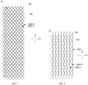
- FIG. 7 is a partial schematic view of a first support member of FIG. 2 in some embodiments of the present disclosure.
- the flexibility of the first support member 12 in the sliding direction X is greater than the flexibility of the first support member 12 in the second direction Z.
- the above design mode with greater flexibility in the sliding direction X may reduce the difficulty of rolling the first support member 12 through the rolling shaft 14, and may also allow the first support member 12 to be rolled with a very small radius.
- the above design mode with less flexibility in the second direction Z may allow the first support member 12 to have a certain degree of rigidity in the second direction Z when unfolding the first support member 12, thereby improving the support effect.
- each of the flexible members 120 extends in a spiral-shape structure.
- This design mode may allow the flexible members 120 to have a certain degree of rigidity in the second direction Z.
- a wire diameter of each of the flexible members 120 is in a range from 0.05mm to 1mm (such as 0.06mm, 0.07mm, 0.08mm, 0.09mm, etc.).
- the outer diameter of the spiral-shape structure formed by each of the flexible members 120 is in a range from 0.05mm to 3mm (such as 0.1mm, 0.5mm, 1mm, 1.5mm, 2mm, 2.5mm, etc.).
- This design mode may reduce the thickness and rolling radius of the final formed first support member 12.
- adjacent flexible members 120 are misaligned and intersect with each other to form the netlike structure.
- the structural design of the flexible members 120 is relatively simple, and adjacent flexible members 120 may be connected to each other without an additional connecting member.
- each of the flexible members 120 includes convex parts 1200 and concave parts 1202 that are alternately disposed.
- a top end A of each convex part 1200 of each of the flexible members 120 intersects with a bottom end B of the corresponding one of the concave parts 1202 of an adjacent one of the flexible members 120.
- FIG. 8 is a structural schematic view of the first support member of FIG. 2 in some embodiments of the present disclosure.
- the first support member 12 includes multiple connecting members 122 and multiple flexible members 120.
- the connecting members 122 are arranged side by side or in parallel with the flexible members 120 in the sliding direction X. Two adjacent of the flexible members 120 are connected by a corresponding one of the connecting members 122.
- This structural design of the first support member 12 is relatively simple and easy to implement.
- each of the flexible members 120 includes convex parts 1200 and concave parts 1202 that are alternately disposed.
- the top A of each convex part 1200 of one of two adjacent flexible members 120 intersects with the connecting member 122 located between the two adjacent flexible members 120.
- the bottom end B of each concave part 1202 of the other of two adjacent flexible members 120 intersects with the connecting member 122 located between the two adjacent flexible members 120.
- the structural design of the first support member 12 is relatively simple and easy to implement.
- each of the connecting members 122 may be a zigzag shape, and each of the connecting members 122 includes corner points 1220 spaced apart from each other. The position where each flexible member 120 intersects with the corresponding one of the connecting members 122 is located at a corresponding one of the corner points 1220.
- FIG. 9 is a structural schematic view of the first support member of FIG. 2 in some embodiments of the present disclosure.
- Multiple ends 1204 of adjacent flexible members 120 intersect with each other. This design mode may reduce the misalignment of the first support member 12 in the second direction Z during rolling or unfolding.
- the ends 1204 of the adjacent flexible members 120 may be flush and connected with each other to form a fixedly locking structure, further reducing the probability of the first support member 12 being misaligned in the second direction Z during rolling or unfolding.
- the second support member 16 includes multiple support strips 160 and a connecting strip 162.
- the multiple support strips 160 are arranged side by side in the second direction Z, and each support strip 160 may extend along the sliding direction X.
- the connecting strip 162 extends along the second direction Z and is fixedly connected to each support strip 160. This design mode may reduce usage cost of the second support member 16.
- the multiple support strips 160 may be configured to support at intervals. That is, the multiple support strips 160 are spaced apart from each other.
- the support strips 160 extending along the sliding direction X may compensate for the rigidity of the first support member 12 in the sliding direction X, so that the joint support effect of the support strip 160 and the first support member 12 is better.
- the connecting strip 162 is fixedly connected to an end of each of the support strips 160 away from the body mechanism 10. This structural design is relatively simple. In some embodiments, the number of the connecting strips 162 may also be multiple, and the second support member 16 may also form the netlike structure. In some embodiments, the connecting strip 162 farthest away from the body mechanism 10 forms the fixed end 164.
- the body mechanism 10 defines multiple accommodate grooves 1006 with the same extending direction.
- Each support strip 160 is located in a corresponding one of the accommodate grooves 1006, and slidably connected to the corresponding one of the accommodate grooves 1006.
- This structural design is relatively simple and may ensure that the sliding direction X of each support strip 160 remains the same.
- the second support member 16 is a magnet, and the first support member 12 may be attracted by the magnet.
- a material of the first support member 12 may be stainless steel, etc. This design mode may allow the unfolded first support member 12 to be tightly attached to the second support member 16 to further improve the support effect.
- FIG. 10 is a partial schematic view illustrating the first support member and a second support member of FIG. 2 in some embodiments of the present disclosure.
- the first support member 12 When the first support member 12 and the second support member 16 are unfolded, the first support member 12 includes a first part 124 and a second part 126 that are alternately disposed.
- An orthogonal projection of the first part 124 on the second support member 16 overlaps with or coincides with the support strips 160.
- An orthogonal projection of the second part 126 on the second support member 16 is staggered with the support strips 160.
- An aperture diameter of the netlike structure of the first part 124 is greater than an aperture diameter of the netlike structure of the second part 122.
- the smaller the aperture diameter of the netlike structure the larger the density of a support mesh of the first support member 12, the better the support performance, but the smaller the rolling performance.
- the netlike structure of the first support member 12 has a density change.
- a part ((i.e. the first part 124) of the first support member 12 corresponding to or facing the second support member 16 has relatively sparse holes, and accordingly the support performance of the first part 124 of the first support member 12 becomes weaker. Due to the support compensation provided by the second support member 16, the support performance of the entire support assembly 1 corresponding to the second support member 16 is not weakened. On the contrary, it may improve the overall rolling performance of the first support member 12.
- each of the support strips 160 in the second support member 16 is a linear and non-retractable structure.
- each of the support strips 160 may also be in a retractable form to reduce a volume occupied by each of the support strips 160.
- each of the support strips 160 includes multiple support parts that are slidably connected in sequence, and one of the multiple support parts is fixedly connected to the translation mechanism 18. This design mode may reduce a volume occupied by the second support member 16.
- FIG. 11 is a structural schematic view of the support assembly in some embodiments of the present disclosure.
- Each of the support strips 160 includes a first support part 1600 and a second support part 1602.
- the outer surface of the first support part 1600 is slidably connected to the outer surface of the second support part 1602, and the second support part 1602 is fixedly connected to the translation mechanism 18.
- the second support part 1602 first slides along the sliding direction X with the translation mechanism 18.
- the second support part 1602 drives the first support part 1600 to slide out of the corresponding one of the accommodate grooves 1006.
- an extending length of the second support part 1602 in the sliding direction X is the same as an extending length of the corresponding one of the accommodate grooves 1006 in the sliding direction X.
- An extending length of the first support part 1600 in the sliding direction X is less than or equal to the extending length of the corresponding one of the accommodate grooves 1006 in the sliding direction X.
- the second support part 1602 defines a groove 16020, and the groove 16020 is configured to accommodate the first support part 1600 and is slidably connected to the first support part 1600.
- FIG. 12 is a structural schematic view of the support assembly in some embodiments of the present disclosure.
- the support strip 160 includes the first support part 1600, the second support part 1602, and a third support part 1604 that are slidably connected to each other.
- the third support part 1604 is fixedly connected to the translation mechanism 18.
- An outer surface of the second support part 1602 is slidably connected to the inner surface of the accommodate space of the first support part 1600, and an outer surface of the third support part 1604 is slidably connected to the inner surface of the accommodate space of the second support part 1602.
- widths of the support strips 160 of the second support member 16 in the second direction Z are the same or equal to each other along a direction away from the body mechanism 10.
- FIG. 13 is a structural schematic view of the second support member of FIG. 2 in some embodiments of the present disclosure.
- the widths of the support strips 160 in the second direction Z gradually increase along the direction away from the body mechanism 10.
- FIG. 14 is a structural schematic view of the second support member of FIG. 2 in some embodiments of the present disclosure.
- the widths of the support strips 160 in the second direction Z sharply and stepwise increase along the direction away from the body mechanism 10, such that a plurality of steps are formed by the support strips 160.
- the above two design modes may allow the support assembly to provide higher support strength in the direction away from the body mechanism.
- the support assembly 1 may also include a rotating shaft 11.
- the rotating shaft 11 is located on a side of the rolling shaft 14 away from the body mechanism 10, and configured to limit the sliding of the flexible screen 2.
- the rotating shaft 11 is configured to be fixedly connected to an end of the flexible screen 2, so that the flexible screen 2 may be rolled on the rotating shaft 11. This design mode may make the rolling and unfolding process of flexible screen 2 easier.
- the first support member 12 and the flexible screen 2 are arranged separately and independently. The flexible screen 2 is rolled and stored on the rotating shaft 11, and the first support member 12 is rolled and stored on the rolling shaft 14. During the rolling and storage process, the first support member 12 will not squeeze or press the flexible screen 2, reducing the probability of damage to the flexible screen 2 during the rolling process.
- the rotating shaft 11 and the rolling shaft 14 are parallel to each other, and the rotating shaft 11 may be fixedly connected to the translation mechanism 18.
- a thickness of the first support member 12 is greater than that of the flexible screen 2, and a radius of the rolling shaft 14 is smaller or less than that of the rotating shaft 11.
- This design mode may make the rolling radius of flexible screen 2 larger during the rolling process, thereby reducing a bending stress of flexible screen 2.
- a cylinder formed by the rolling shaft 14 and the first support member 12 located on a periphery of the rolling shaft 14 has a first radius.
- a cylinder formed by the rotating shaft 11 and the flexible screen 2 located on a periphery of the rotating shaft 11 has a second radius. The first radius is smaller or less than the second radius, and the difference between the first radius and the second radius is the thickness of the flexible screen 2, so that the display surface of the flexible screen 2 exposed after fully rolling is flat.
- Some embodiments of the present disclosure also provide a display device.
- the rotating shaft 11, the rolling shaft 14, and the second support member 16 follow the translation mechanism 18 to move away from the body mechanism 10 along the sliding direction X, because the rotating shaft 11, the rolling shaft 14, and the second support member 16 are fixedly connected to the translation mechanism 18.
- the flexible screen 2 rolled on the rotating shaft 11 is unfolded, and the first support member 12 rolled on the rolling shaft 14 is unfolded.
- the second support member 16 accommodated in the accommodate groove 1006 of the body mechanism 10 slides out of the accommodate groove 1006 and is stacked on the side of the first support member 12 away from the flexible screen 2.
- the first support member 12 and the second support member 16 may support the flexible screen 2 located on the outer side of the body mechanism 10.
- the rotating shaft 11, the rolling shaft 14, and the second support member 16 follow the translation mechanism 18 to approach the body mechanism 10 along the sliding direction X, because the rotating shaft 11, the rolling shaft 14, and the second support member 16 are fixedly connected to the translation mechanism 18.
- the flexible screen 2 located on the outer side of the body mechanism 10 and unfolded may be rolled on the rotating shaft 11.
- the first support member 12 located on the outer side of the body mechanism 10 and unfolded may be rolled on the rolling shaft 14.
- the second support member 16 sliding out of the accommodate groove 1006 may be slid into the accommodate groove 1006.
- the rotating shaft 11 and the second support member 16 follow the translation mechanism 18 to move away from the body mechanism 10 along the sliding direction X, because the rotating shaft 11 and the second support member 16 are fixedly connected to the translation mechanism 18. Because the rolling shaft 14 is fixedly connected to the body mechanism 10, the rolling shaft 14 moves away from the translation mechanism 18 along the sliding direction X with the body mechanism 10.
- the flexible screen 2 rolled on the rotating shaft 11 is unfolded, and the first support member 12 rolled on the rolling shaft 14 is unfolded.
- the second support member 16 accommodated in the accommodate groove 1006 of the body mechanism 10 slides out of the accommodate groove 1006 and is stacked on the side of the first support member 12 away from the flexible screen 2.
- the first support member 12 and the second support member 16 may support the flexible screen 2 located on the outer side of the body mechanism 10.
- the rotating shaft 11 and the second support member 16 follow the translation mechanism 18 to approach the body mechanism 10 along the sliding direction X, because the rotating shaft 11 and the second support member 16 are fixedly connected to the translation mechanism 18. Because the rolling shaft 14 is fixedly connected to the body mechanism 10, the rolling shaft 14 follow the body mechanism 10 to approach the translation mechanism 18 along the sliding direction X.
- the flexible screen 2 located on the outer side of the body mechanism 10 and unfolded may be rolled on the rotating shaft 11.
- the first support member 12 located on the outer side of the body mechanism 10 and unfolded may be rolled on the rolling shaft 14.
- the second support member 16 sliding out of the accommodate groove 1006 may be slid into the accommodate groove 1006.
- FIG. 15 is a structural schematic view of the support assembly and the flexible screen in some embodiments of the present disclosure.
- the first support member 12 is configured to fit with or be attached to the flexible screen 2.
- the rolling shaft 14 is configured to drive the flexible screen 2 and the first support member 12 to roll or unfold together.
- the display device including the flexible screen 2 and the support assembly 1 is a rollable display device.
- the flexible screen 2 and the support assembly 1 may also form a slidable display device.
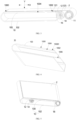
- FIGS. 16 and 17 FIG. 16 is a structural schematic view of a display device in some embodiments of the present disclosure.
- FIG. 17 is a structural schematic view of the display device of FIG. 16 when the display device is fully unfolded.
- the flexible screen 2 partially surrounds a side of the rotating shaft 11 away from the body mechanism 10 and slides along a circumferential direction of the rotating shaft 11.
- the flexible screen 2 located on the side of the first plate body 100 facing the second plate body 102 is accommodated in a non-rolling form.
- the flexible screen 2 when the flexible screen 2 is not fully unfolded, the flexible screen 2 includes a first part 20 and a second part 22 connected to each other.
- the first part 20 is located on the first plate body 100 and may be fixedly connected to the first plate body 100.
- the other parts of the flexible screen 2 except the first part 20 form the second part 22.
- a sub-part of the second part 22 may be located between the first plate body 100 and the second plate body 102, and the sub-part of the second part 22 may be parallel to the first part 20.
- the second part 22 may slide away from the outer side of the body mechanism 10 along the rotating shaft 11 to roll or unfold.
- the current mainstream flexible screen supports include perforated steel-sheet-type supports and watch-chain-type supports.
- supporting and rolling properties of the perforated steel-sheet-type supports are related to their material properties, thickness, and density of holes.
- thicknesses will be inevitably reduced, apertures will be inevitably increased, and spacing between adjacent holes will be inevitably reduced.
- it will inevitably weaken the supporting property and damage the perforated steel-sheet-type supports.
- each perforated steel-sheet-type support is a whole piece structure, and an accumulated stress is large during rolling, which will cause a large gap between adjacent perforated steel-sheet-type supports.
- the watch-chain-type support includes multiple joints that are connected together through thin shafts.
- the rolling radius of the watch-chain-type support depends on lengths of the joints and rolling diameters of thin shafts. Due to the influence of structure and manufacturing process, it is impossible to achieve extremely small joint length and rolling diameter.
- Each of the joints is fixed by the thin shafts, thus the watch-chain-type support cannot move flexibly along a rolling direction of the flexible screen, and cannot roll together with the flexible screen.
- the first support member of the support assembly is a netlike structure formed by spiral flexible members.
- the connection of each spiral flexible member in the sliding direction X is very flexible, each flexible member may be rolled in the sliding direction X with a very small radius, and each spiral flexible member has a certain strength in the second direction Z.
- the two adjacent of the flexible members are connected to each other only through a simple intersection.
- the first support member may flexibly move a small distance in the sliding direction X, to compensate for the displacement difference caused by being different from a neutral layer of the flexible screen during the rolling process.
- the first support member and the flexible screen may be arranged side by side and rolled on different shafts. In some embodiments, the first support member may also be attached to the flexible screen and rolled on the same rolling shafts with the flexible screen, and the design mode is more flexible.
- the second support member is arranged below the first support member. The second support member may provide a certain support strength for the first support member and the flexible screen disposed on or above the second support member. When the second support member has magnetism, the second support member may also adsorb the first support member disposed on or above the second support member, making the loose structure of the first and second support members to be tightly adhered to each other and further improving an overall strength of the first support member.
- FIG. 18 is a partial schematic view of the first support member of FIG. 2 in some embodiments of the present disclosure.
- a wire diameter of each of the flexible members of the first support member in some embodiments of the present disclosure is 0.3mm.
- a diameter D1 of the spiral-shape structure formed by each of the flexible members is 1.2mm.
- An aperture diameter D2 of the netlike structure of the first support member is 0.5mm (i.e. 1.2-0.3*2-0.1, and a gap at the intersection is 0.1).
- a rolling radius of the first support member is half of a diameter of the spiral-shape structure (i.e. 0.6mm).
- a support force born by the first supporting member is 3N in a deformation range of 1mm.
- the aperture diameter of the netlike structure of the first support member is reduced to 0.1mm; and within the deformation range of 1mm, the support force born by an area of the first support member which is not supported by the support strips is 8N.
- the perforated steel-sheet-type support has an aperture diameter of 0.5mm, a hole spacing of 0.5mm, a thickness of 0.05mm, and a rolling radius of 1mm.
- the support force born by the perforated steel-sheet-type support is 0.5N.
- the second support member is disposed on a side of the perforated steel-sheet-type support, and the distance between adjacent support strips of the second support member is 50mm, the support force born by an area of the perforated steel-sheet-type support which is not supported by the support strips is 2N.
- the first support member provided in some embodiments of the present disclosure has a smaller rolling radius and may improve the support force when unfolding the first support member.
Landscapes
- Engineering & Computer Science (AREA)
- Theoretical Computer Science (AREA)
- General Engineering & Computer Science (AREA)
- Computer Hardware Design (AREA)
- Physics & Mathematics (AREA)
- General Physics & Mathematics (AREA)
- Human Computer Interaction (AREA)
- Signal Processing (AREA)
- Mechanical Engineering (AREA)
- Microelectronics & Electronic Packaging (AREA)
- Devices For Indicating Variable Information By Combining Individual Elements (AREA)
- Overhead Projectors And Projection Screens (AREA)
Abstract
Description
- The present application claims priorities to
Chinese Patent Application No. 202210508007.9, entitled "SUPPORT ASSEMBLY AND DISPLAY DEVICE", filed on May 10, 2022 Chinese Patent Application No. 202211215762.4, entitled "SUPPORT ASSEMBLY AND DISPLAY DEVICE", filed on September 30, 2022 - The present disclosure relates to the technical field of display, and in particular to a support assembly and a display device.
- With the development of display technology, flexible screens appear. Sizes of the flexible screens may be adjusted according to display requirements, and it may minimize spaces occupied by the flexible screens during storage and carrying of the flexible screens.
- At present, in order to improve the display effect of an unfolded flexible screen, a support assembly is generally disposed below the unfolded flexible screen. How to reduce a volume of the support assembly has become a research hotspot.
- The present disclosure provides a support assembly and a display device. The support assembly may provide more effective support for an unfolded flexible screen, and reduce a volume of a first support member after rolling the first support member.
- To solve the above technical problems, a technical solution adopted in the present disclosure is to provide a support assembly that is configured to support a flexible screen. The support assembly includes a body mechanism and a first support member. A first surface of the body mechanism is configured to support a part of the flexible screen. At least a part of the first support member is located an outer side of the body mechanism, disposed side by side with the body mechanism, and configured to support another part of the flexible screen which extends out of the first surface. The first support member includes a first end and a second end disposed along a length direction of the first support member. The first end is fixed relative to the body mechanism, and the second end is configured to slide along a direction close to or away from the body mechanism. In a sliding direction, the first support member includes a plurality of flexible members disposed side by side, and two adjacent of the plurality of flexible members are connected to each other to form a netlike structure.
- To solve the above technical problems, another technical solution adopted in the present disclosure is to provide a display device. The display device includes a flexible screen and the support assembly described above, and the support assembly is configured to support the flexible screen.
- Different from the existing technologies, the effects of the present disclosure are as follows. The support assembly provided in the present disclosure is configured to support the flexible screen. The support assembly includes the body mechanism and the first support member. The first surface of the body mechanism is configured to support a part of the flexible screen. The first support member is configured to support another part of the flexible screen which extends out of the first surface. The first support member is configured to provide strong support for the flexible screen, especially when users touch the flexible screen. In a sliding direction of the first support member, the first support member includes multiple flexible members disposed side by side, and two adjacent flexible members are connected to each other to form a netlike structure. This design mode may improve the flexibility of the first support member in the sliding direction. During subsequent rolling of the flexible screen, the first support member may be rolled with a smaller radius in the sliding direction, to reduce a volume occupied by the first support member, which facilitates to make the display device light and thin.
- In order to more clearly illustrate the technical solutions in some embodiments of the present disclosure, hereinafter, a brief introduction will be given to the accompanying drawings that are used in the description of some embodiments. Obviously, the accompanying drawings in the description below are merely some embodiments of the present disclosure. For those of ordinary skill in the art, other accompanying drawings may be obtained based on these accompanying drawings without any creative efforts.
-
FIG. 1 is a structural schematic view of a support assembly in some embodiments of the present disclosure. -
FIG. 2 is an exploded schematic view of the support assembly ofFIG. 1 in some embodiments of the present disclosure. -
FIG. 3 is a structural schematic view illustrating a part of the support assembly ofFIG. 1 and a flexible screen in some embodiments of the present disclosure. -
FIG. 4 is a structural schematic view of a body mechanism ofFIG. 1 from another perspective. -
FIG. 5 is a structural schematic view illustrating a support assembly and a flexible screen in some embodiments of the present disclosure. -
FIG. 6 is an exploded schematic view of the support assembly ofFIG. 5 . -
FIG. 7 is a partial schematic view of a first support member ofFIG. 2 in some embodiments of the present disclosure. -
FIG. 8 is a structural schematic view of the first support member ofFIG. 2 in some embodiments of the present disclosure. -
FIG. 9 is a structural schematic view of the first support member ofFIG. 2 in some embodiments of the present disclosure. -
FIG. 10 is a partial schematic view illustrating the first support member and a second support member ofFIG. 2 in some embodiments of the present disclosure. -
FIG. 11 is a structural schematic view of the support assembly in some embodiments of the present disclosure. -
FIG. 12 is a structural schematic view of the support assembly in some embodiments of the present disclosure. -
FIG. 13 is a structural schematic view of the second support member ofFIG. 2 in some embodiments of the present disclosure. -
FIG. 14 is a structural schematic view of the second support member ofFIG. 2 in some embodiments of the present disclosure. -
FIG. 15 is a structural schematic view of the support assembly and the flexible screen in some embodiments of the present disclosure. -
FIG. 16 is a structural schematic view of a display device in some embodiments of the present disclosure. -
FIG. 17 is a structural schematic view of the display device ofFIG. 16 when the display device is fully unfolded. -
FIG. 18 is a partial schematic view of the first support member ofFIG. 2 in some embodiments of the present disclosure. - The technical solutions in some embodiments of the present disclosure may be clearly and completely described in conjunction with accompanying drawings in some embodiments of the present disclosure. Obviously, the described embodiments are only a part of the embodiments of the present disclosure, and not all embodiments. Based on the embodiments in the present disclosure, all other embodiments obtained by those of ordinary skill in the art without creative effort are within the scope of the present disclosure.
- Referring to
FIGS. 1 and 2, FIG. 1 is a structural schematic view of a support assembly in some embodiments of the present disclosure, andFIG. 2 is an exploded schematic view of the support assembly ofFIG. 1 in some embodiments of the present disclosure. Asupport assembly 1 is configured to support a flexible screen. The flexible screen may be a flexible OLED (Organic Light Emitting Diode) screen, a flexible Micro LED screen, or the like. Thesupport assembly 1 includes abody mechanism 10 and afirst support member 12. - In some embodiments, the
body mechanism 10 includes afirst surface 1000, and thefirst surface 1000 is configured to support a part of a flexible screen. In some embodiments, thefirst surface 1000 is also configured to fix the part of the flexible screen through an adhesive element or the like. At least a part of thefirst support member 12 is located on an outer side of thebody mechanism 10 and arranged side by side with thebody mechanism 10, to support the flexible screen extending out of thefirst surface 1000. Thefirst support member 12 includes afirst end 121 and asecond end 123, and thefirst end 121 and thesecond end 123 are disposed along a length direction of thefirst support member 12. Thefirst end 121 and thesecond end 123 respectively refer to two opposite ends along the length direction when thefirst support member 12 is fully unfolded. Thefirst end 121 is fixed relative to thebody mechanism 10, and thesecond end 123 may slide in a direction close to or away from thebody mechanism 10, to change a size of a support surface formed by thefirst support member 12 and thebody mechanism 10. As shown inFIG. 7 , thefirst support member 12 includes multipleflexible members 120 disposed side by side in a sliding direction X, and adjacentflexible members 120 are connected to each other to form a netlike structure. This design mode may improve flexibility of thefirst support member 12 in the sliding direction X. In some embodiments, shapes of holes of the netlike structure may be approximated as a quadrilateral, such as a rhombus, etc. - In the above design mode, the
first support member 12 is configured to support the flexible screen that extends out of thefirst surface 1000, thereby providing strong support for the flexible screen, especially when users touch the flexible screen. In the sliding direction X of thefirst support member 12, thefirst support member 12 includes multipleflexible members 120 arranged side by side or in parallel, and adjacentflexible members 120 are connected to each other to form the netlike structure. This design mode may improve the flexibility of thefirst support member 12 in the sliding direction X. During subsequent rolling of the flexible screen, thefirst support member 12 may be rolled with a smaller radius in the sliding direction, to reduce a volume occupied by thefirst support member 12, which facilitates to make the display device light and thin. - Referring to
FIG. 2 , thesupport assembly 1 provided in some embodiments of the present disclosure further includes asecond support member 16. Thesecond support member 16 has a certain degree of rigidity, and the flexibility of thesecond support member 16 is less than that of thefirst support member 12. Thesecond support member 16 is stacked on a side of thefirst support member 12 away from theflexible screen 2 when thefirst support member 12 supports theflexible screen 2. - In some embodiments, as shown in
FIG. 3, FIG. 3 is a structural schematic view illustrating a part of the support assembly ofFIG. 1 and a flexible screen in some embodiments of the present disclosure. Thebody mechanism 10 is configured to support theflexible screen 2 located on thefirst surface 1000 of thebody mechanism 10. The remaining part of theflexible screen 2 located on the outer side of thebody mechanism 10 is supported by thefirst support member 12 and thesecond support member 16 that are stacked on each other during unfolding the remaining part of theflexible screen 2. Thefirst support member 12 with a certain degree of flexibility may better fit with or be better attached to theflexible screen 2, and thesecond support member 16 with a certain degree of rigidity may compensate for the strength of thefirst support member 12. Thefirst support member 12 and thesecond support member 16 may provide strong support for theflexible screen 2, especially when the users touch theflexible screen 2. - In some embodiments, the
second support member 16 is slidably connected to thebody mechanism 10. A sliding direction X of thesecond end 123 relative to thebody mechanism 10 is the same as a sliding direction X of thesecond support member 16 relative to thebody mechanism 10. This design mode may allow thefirst support member 12 and thesecond support member 14 to synchronously translate, to provide synchronous support for an unfolded flexible screen, thereby achieving a better support effect. - In one embodiment, as shown in
FIG. 3 , thesecond end 123 and thesecond support member 16 simultaneously approach or move away from thebody mechanism 10 along the sliding direction X. This design mode allows thesupport assembly 1 to have a relatively simple structure. - In some embodiments, referring to
FIG. 2 , thesupport assembly 1 provided in the present disclosure also includes atranslation mechanism 18, and thetranslation mechanism 18 is slidably connected to thebody mechanism 10. In the sliding direction X, thesecond support member 16 includes afixed end 164, and thesecond end 123 of thefirst support member 12 and thefixed end 164 are fixed relative to thetranslation mechanism 18. In the above design mode, thetranslation mechanism 18 may synchronously drive thesecond support member 16 and thesecond end 123 to slide relative to thebody mechanism 10, in order to reduce the difficulty of sliding thesecond support member 16 and thesecond end 123 relative to thebody mechanism 10. - Referring to
FIG. 3 , thesupport assembly 1 provided in the present disclosure also includes a rollingshaft 14, and the rollingshaft 14 is configured to roll thefirst support member 12. One of thefirst end 121 and thesecond end 123 is fixedly connected to the rollingshaft 14. The rollingshaft 14 may make the process of rolling and unfolding thefirst support member 12 relatively simple. - In some embodiments, as shown in
FIGS. 2 and3 , the rollingshaft 14 may approach or move away from thebody mechanism 10 along the sliding direction X, driving thefirst support member 12 to roll or unfold. The rollingshaft 14 may be located on the outer side of thebody mechanism 10. In some embodiments, the rollingshaft 14 may be disposed side by side with thebody mechanism 10 in the sliding direction X where the rollingshaft 14 slides relative to thebody mechanism 10. Thefirst end 121 of thefirst support member 12 is fixed on thebody mechanism 10, and thesecond end 123 of thefirst support member 12 is fixed on the rollingshaft 14. The rollingshaft 14 may drive thefirst support member 12 to roll or unfold. In some embodiments, the rollingshaft 14 approaches thebody mechanism 10 along the sliding direction X, and thesecond end 123 also approaches thebody mechanism 10 along the sliding direction X. A part of thefirst support member 12 is rolled on the rollingshaft 14, and an area of a support surface formed by thefirst support member 12 decreases. The rollingshaft 14 moves away from thebody mechanism 10 along the sliding direction X, and thesecond end 123 also moves away from thebody mechanism 10 along the sliding direction X because thesecond end 123 is fixed on the rollingshaft 14. The part of thefirst support member 12 rolled on the rollingshaft 14 is unfolded, and the area of the support surface formed by thefirst support member 12 increases. In the above design mode, the method of driving thefirst support member 12 to roll or unfold through the rollingshaft 14 is relatively simple, and the process of rolling or unfolding thefirst support member 12 is easier. - As shown in
FIGS. 2 and3 , in the sliding direction X, an edge of thefirst surface 1000 of thebody mechanism 10 is adjacent to thefirst support member 12, and the edge of thefirst surface 1000 of thebody mechanism 10 is provided with astep part 1002. Thefirst end 121 of thefirst support member 12 is located on thestep part 1002 and fixedly connected to thestep part 1002. This design mode may reduce the difficulty of fixing thefirst support member 12 with thebody mechanism 10, which facilitates to reduce the thickness of thesupport assembly 1. - In some embodiments, the
first end 121 of thefirst support member 12 may be fixedly connected to thestep part 1002 through the adhesive element or the like. - In some embodiments, the
body mechanism 10 includes afirst plate body 100. Thefirst plate body 100 includes thefirst surface 1000 and asecond surface 1004 opposite to thefirst surface 1000. Thefirst plate body 100 includes thestep part 1002. In a first direction Y that is directed from thefirst surface 1000 to thesecond surface 1004, a thickness of thefirst support member 12 is the same as a height of thestep part 1002. This design mode may allow a side of the unfoldedfirst support member 12 facing theflexible screen 2 to be flush with thefirst surface 1000, so as to make the unfoldedflexible screen 2 more flat and improve the display effect. - Referring to
FIGS. 2 and4, FIG. 4 is a structural schematic view of a body mechanism ofFIG. 1 from another perspective. Thebody mechanism 10 further defines an accommodategroove 1006. At least a part of thesecond support member 16 is located in the accommodategroove 1006 and is slidably connected to the accommodategroove 1006. That is, the accommodategroove 1006 may play a certain guiding role in the sliding of thesecond support member 16. In some embodiments, an extending direction of the accommodategroove 1006 is parallel to the sliding direction X, so that a direction of unfolding thesecond support member 16 is the same as a direction of unfolding thefirst support member 12. Thesecond support member 16 and thefirst support member 12 may synchronously support theflexible screen 2. - In some embodiments, both the
step part 1002 and the accommodategroove 1006 may be located on thefirst plate body 100, and the accommodategroove 1006 is located on a side of thesecond surface 1004. The structural design of thebody mechanism 10 is relatively simple. - In some embodiments, as shown in
FIGS. 2 and4 , in the first direction Y that is directed from thefirst surface 1000 to thesecond surface 1004, thestep part 1002 includes a bottom 10020, and the bottom 10020 includes a hollow area. The accommodategroove 1006 extends to the hollow area, and a side of thesecond support member 16 facing thefirst support member 12 is flush with thebottom 10020. This design mode may allow thesecond support member 16 to be in direct contact with thefirst support member 12, and the joint support formed by thesecond support member 16 and thefirst support member 12 may better support the flexible screen. - In some embodiments, as shown in
FIG. 2 , a second direction Z is perpendicular to the sliding direction X and the first direction Y. In the second direction Z, a width of thebody mechanism 10 is greater than a width of thesecond support member 16, and a width of the accommodategroove 1006 may be equal to the width of thesecond support member 16 slidable in the accommodategroove 1006. This design mode may allow only a part of thebottom 10020 of thestep part 1002 to be passed through or penetrated by the accommodategroove 1006, and the remaining part of the bottom 10020 that is not passed through or penetrated by the accommodategroove 1006 may be fixedly connected to thefirst support member 12, to ensure the fixing effect between thefirst support member 12 and thestep part 1002. - In some embodiments, referring to
FIGS. 1 and 2 , thesupport assembly 1 provided in the present disclosure further includes thetranslation mechanism 18, and thetranslation mechanism 18 is slidably connected to thebody mechanism 10. In the sliding direction X where the rollingshaft 14 slides relative to thebody mechanism 10, thesecond support member 16 includes thefixed end 164, the rollingshaft 14 and thefixed end 164 are fixedly connected to thetranslation mechanism 18, and the rollingshaft 14 is located on the side of thefixed end 164 away from thebody mechanism 10. In the above design mode, thetranslation mechanism 18 may synchronously drive thesecond support member 16 and the rollingshaft 14 to slide relative to thebody mechanism 10, in order to reduce the difficulty of sliding thesecond support member 16 and the rollingshaft 14 relative to thebody mechanism 10. - In some embodiments, in the direction perpendicular to the first surface 1000 (i.e. the first direction Y), the
body mechanism 10 further includes asecond plate body 102 that is opposite to and spaced apart from thefirst plate body 100. Thetranslation mechanism 18 includes at least oneextension plate body 180. Theextension plate body 180 is located between thefirst plate body 100 and thesecond plate body 102, and theextension plate body 180 is slidably connected to thefirst plate body 100 and thesecond plate body 102. In some embodiments, each of thefirst plate body 100 and thesecond plate body 102 defines a guide groove at a position corresponding to theextension plate body 180. An extending direction of the guide groove is parallel to the sliding direction X. Two opposite sides of theextension plate body 180 in the first direction Y are respectively arranged in one guide groove at a corresponding position. The sliding connection mode between thebody mechanism 10 and thetranslation mechanism 18 is relatively simple. - In some embodiments, as shown in
FIG. 2 , in the second direction Z, thetranslation mechanism 18 includes twoextension plate bodies 180 that are opposite to and spaced apart from each other. Thefirst plate body 100 includes twofirst edges 1008 that are opposite to and spaced apart from each other. Each of theextension plate bodies 180 is provided at a position of a corresponding one of thefirst edges 1008. - In some embodiments, the
fixed end 164 of thesecond support member 16 and two opposite ends of the rollingshaft 14 in the second direction Z may be fixedly connected to the twoextension plate bodies 180, respectively. - In some embodiments, the
translation mechanism 18 may further include a first connectingplate body 182 that connects twoextension plate bodies 180. The first connectingplate body 182 is located on a side of each of theextension plate bodies 180 away from thebody mechanism 10. In some embodiments, thebody mechanism 10 further includes a second connectingplate body 104 that connects thefirst plate body 100 and thesecond plate body 102. The second connectingplate body 104 is located on a side of thefirst plate body 100 away from thetranslation mechanism 18. - In some embodiments, the rolling
shaft 14 is located on the outer side of thebody mechanism 10, and the rollingshaft 14 may approach or move away from thebody mechanism 10. In some embodiments, the rollingshaft 14 may also be fixed relative to thebody mechanism 10. In some embodiments, referring toFIGS. 5-6 ,FIG. 5 is a structural schematic view illustrating a support assembly and a flexible screen in some embodiments of the present disclosure.FIG. 6 is an exploded schematic view of the support assembly ofFIG. 5 . In some embodiments, thesupport assembly 1 ofFIGS. 5-6 is different from thesupport assembly 1 ofFIG. 2 in that: thefirst end 121 of thefirst support member 12 is fixed on the rollingshaft 14, the rollingshaft 14 is fixed relative to thebody mechanism 10, and thesecond end 123 of thefirst support member 12 is configured to approach or move away from thebody mechanism 10 along the sliding direction X. In some embodiments, thesecond end 123 of thefirst support member 12 is fixedly connected to thetranslation mechanism 18, and thefixed end 164 of thesecond support member 16 is located on a side away from thebody mechanism 10. The rollingshaft 14 may slide in a direction close to or away from thetranslation mechanism 18 to drive thefirst support member 12 to roll or unfold. The sliding direction X of thetranslation mechanism 18 relative to thebody mechanism 10 is the same as the sliding direction X of thesecond support member 16 relative to thebody mechanism 10. In some embodiments, since the rollingshaft 14 is fixed relative to thebody mechanism 10, the rollingshaft 14 slides in the direction close to or away from thetranslation mechanism 18, that is, thebody mechanism 10 slides in the direction close to or away from thetranslation mechanism 18. In other words, thetranslation mechanism 18 slides in the direction close to or away from thebody mechanism 10. In case that thetranslation mechanism 18 approaches thebody mechanism 10 or the rollingshaft 14 along the sliding direction X, thesecond end 123 also approaches thebody mechanism 10 or the rollingshaft 14 along the sliding direction X, and the rollingshaft 14 drives thefirst support member 12 to roll. In case that thetranslation mechanism 18 moves away from thebody mechanism 10 or the rollingshaft 14 along the sliding direction X, thesecond end 123 also moves away from thebody mechanism 10 or the rollingshaft 14 along the sliding direction X, and the rollingshaft 14 drives thefirst support member 12 to unfold. This design mode may allow thesupport assembly 1 to have a relatively simple structure, and this design mode may provide better smoothness and feel. Thefirst support member 12 and thesecond support member 16 have a larger support area for theflexible screen 2. - In some embodiments, as shown in
FIGS. 5 and6 , the rollingshaft 14 is located on an inner side of thebody mechanism 10, and thebody mechanism 10 includes ahollow part 106. Thefirst end 121 of thefirst support member 12 passes through thehollow part 106 and is fixedly connected to the rollingshaft 14. This structural design mode is relatively simple. - In some embodiments, as shown in
FIGS. 5 and6 , thebody mechanism 10 includes thefirst plate body 100 and thesecond plate body 102 that are opposite to and spaced apart from each other. The rollingshaft 14 is located between thefirst plate body 100 and thesecond plate body 102. A side of thefirst plate body 100 away from thesecond plate body 102 is configured to support the flexible screen 2 (as shown inFIG. 5 ). Thefirst plate body 100 is provided with thehollow part 106. The structural of thebody mechanism 10 with thehollow part 106 is relatively simple. - In some embodiments, the
first plate body 100 is provided with the accommodategroove 1006 that is slidably connected to thesecond support member 16. The specific structure of the accommodategroove 1006 is described in the above embodiments and will not be further described here. Thesecond support member 16 includes thefixed end 164 fixed to thetranslation mechanism 18. In the sliding direction X, thehollow part 106 is farther away from thefixed end 164 than the accommodategroove 1006. - In some embodiments, a length extending direction of the accommodate
groove 1006 is parallel to the sliding direction X, and a length extending direction of thehollow part 106 is parallel to the second direction Z. And/or, one end of thefirst support member 12 may be fixedly connected to thefixed end 164 of thesecond support member 16. This design mode may allow thefirst support member 12 and thesecond support member 16 to synchronously support the unfoldedflexible screen 2. - Referring to
FIG. 7, FIG. 7 is a partial schematic view of a first support member ofFIG. 2 in some embodiments of the present disclosure. The flexibility of thefirst support member 12 in the sliding direction X is greater than the flexibility of thefirst support member 12 in the second direction Z. The above design mode with greater flexibility in the sliding direction X may reduce the difficulty of rolling thefirst support member 12 through the rollingshaft 14, and may also allow thefirst support member 12 to be rolled with a very small radius. The above design mode with less flexibility in the second direction Z may allow thefirst support member 12 to have a certain degree of rigidity in the second direction Z when unfolding thefirst support member 12, thereby improving the support effect. - In some embodiments, in the second direction Z, each of the
flexible members 120 extends in a spiral-shape structure. This design mode may allow theflexible members 120 to have a certain degree of rigidity in the second direction Z. In some embodiments, a wire diameter of each of theflexible members 120 is in a range from 0.05mm to 1mm (such as 0.06mm, 0.07mm, 0.08mm, 0.09mm, etc.). The outer diameter of the spiral-shape structure formed by each of theflexible members 120 is in a range from 0.05mm to 3mm (such as 0.1mm, 0.5mm, 1mm, 1.5mm, 2mm, 2.5mm, etc.). This design mode may reduce the thickness and rolling radius of the final formedfirst support member 12. - In some embodiments, in the sliding direction X, adjacent
flexible members 120 are misaligned and intersect with each other to form the netlike structure. The structural design of theflexible members 120 is relatively simple, and adjacentflexible members 120 may be connected to each other without an additional connecting member. - In some embodiments, as shown in
FIG. 7 , each of theflexible members 120 includesconvex parts 1200 andconcave parts 1202 that are alternately disposed. A top end A of eachconvex part 1200 of each of theflexible members 120 intersects with a bottom end B of the corresponding one of theconcave parts 1202 of an adjacent one of theflexible members 120. The above mode of forming thefirst support member 12 is relatively simple and easy to implement. - In other embodiments, the
first support member 12 may also be formed by other structural design modes. In some embodiments, referring toFIG. 8, FIG. 8 is a structural schematic view of the first support member ofFIG. 2 in some embodiments of the present disclosure. Thefirst support member 12 includes multiple connectingmembers 122 and multipleflexible members 120. The connectingmembers 122 are arranged side by side or in parallel with theflexible members 120 in the sliding direction X. Two adjacent of theflexible members 120 are connected by a corresponding one of the connectingmembers 122. This structural design of thefirst support member 12 is relatively simple and easy to implement. - In some embodiments, as shown in
FIG. 8 , in the sliding direction X, allflexible members 120 are aligned with each other. Each of theflexible members 120 includesconvex parts 1200 andconcave parts 1202 that are alternately disposed. The top A of eachconvex part 1200 of one of two adjacentflexible members 120 intersects with the connectingmember 122 located between the two adjacentflexible members 120. The bottom end B of eachconcave part 1202 of the other of two adjacentflexible members 120 intersects with the connectingmember 122 located between the two adjacentflexible members 120. The structural design of thefirst support member 12 is relatively simple and easy to implement. - In some embodiments, each of the connecting
members 122 may be a zigzag shape, and each of the connectingmembers 122 includescorner points 1220 spaced apart from each other. The position where eachflexible member 120 intersects with the corresponding one of the connectingmembers 122 is located at a corresponding one of the corner points 1220. - In some embodiments, referring to
FIG. 9, FIG. 9 is a structural schematic view of the first support member ofFIG. 2 in some embodiments of the present disclosure. Multiple ends 1204 of adjacentflexible members 120 intersect with each other. This design mode may reduce the misalignment of thefirst support member 12 in the second direction Z during rolling or unfolding. In some embodiments, theends 1204 of the adjacentflexible members 120 may be flush and connected with each other to form a fixedly locking structure, further reducing the probability of thefirst support member 12 being misaligned in the second direction Z during rolling or unfolding. - In some embodiments, as shown in
FIG. 2 , thesecond support member 16 includes multiple support strips 160 and a connectingstrip 162. The multiple support strips 160 are arranged side by side in the second direction Z, and eachsupport strip 160 may extend along the sliding direction X. The connectingstrip 162 extends along the second direction Z and is fixedly connected to eachsupport strip 160. This design mode may reduce usage cost of thesecond support member 16. - In some embodiments, as shown in
FIGS. 2 and7 , due to the certain rigidity of thefirst support member 12 in the second direction Z, the multiple support strips 160 may be configured to support at intervals. That is, the multiple support strips 160 are spaced apart from each other. The support strips 160 extending along the sliding direction X may compensate for the rigidity of thefirst support member 12 in the sliding direction X, so that the joint support effect of thesupport strip 160 and thefirst support member 12 is better. - In some embodiments, the connecting
strip 162 is fixedly connected to an end of each of the support strips 160 away from thebody mechanism 10. This structural design is relatively simple. In some embodiments, the number of the connectingstrips 162 may also be multiple, and thesecond support member 16 may also form the netlike structure. In some embodiments, the connectingstrip 162 farthest away from thebody mechanism 10 forms thefixed end 164. - In some embodiments, as shown in
FIGS. 2 and4 , thebody mechanism 10 defines multiple accommodategrooves 1006 with the same extending direction. Eachsupport strip 160 is located in a corresponding one of the accommodategrooves 1006, and slidably connected to the corresponding one of the accommodategrooves 1006. This structural design is relatively simple and may ensure that the sliding direction X of eachsupport strip 160 remains the same. - In some embodiments, the
second support member 16 is a magnet, and thefirst support member 12 may be attracted by the magnet. In some embodiments, a material of thefirst support member 12 may be stainless steel, etc. This design mode may allow the unfoldedfirst support member 12 to be tightly attached to thesecond support member 16 to further improve the support effect. - In some embodiments, referring to
FIG. 10, FIG. 10 is a partial schematic view illustrating the first support member and a second support member ofFIG. 2 in some embodiments of the present disclosure. When thefirst support member 12 and thesecond support member 16 are unfolded, thefirst support member 12 includes afirst part 124 and asecond part 126 that are alternately disposed. An orthogonal projection of thefirst part 124 on thesecond support member 16 overlaps with or coincides with the support strips 160. An orthogonal projection of thesecond part 126 on thesecond support member 16 is staggered with the support strips 160. An aperture diameter of the netlike structure of thefirst part 124 is greater than an aperture diameter of the netlike structure of thesecond part 122. Generally speaking, the smaller the aperture diameter of the netlike structure, the larger the density of a support mesh of thefirst support member 12, the better the support performance, but the smaller the rolling performance. In the above design mode, in the second direction Z, the netlike structure of thefirst support member 12 has a density change. A part ((i.e. the first part 124) of thefirst support member 12 corresponding to or facing thesecond support member 16 has relatively sparse holes, and accordingly the support performance of thefirst part 124 of thefirst support member 12 becomes weaker. Due to the support compensation provided by thesecond support member 16, the support performance of theentire support assembly 1 corresponding to thesecond support member 16 is not weakened. On the contrary, it may improve the overall rolling performance of thefirst support member 12. - In some embodiments, referring to
FIG. 2 orFIG. 6 , each of the support strips 160 in thesecond support member 16 is a linear and non-retractable structure. In some embodiments, each of the support strips 160 may also be in a retractable form to reduce a volume occupied by each of the support strips 160. In some embodiments, each of the support strips 160 includes multiple support parts that are slidably connected in sequence, and one of the multiple support parts is fixedly connected to thetranslation mechanism 18. This design mode may reduce a volume occupied by thesecond support member 16. - In some embodiments, outer surfaces of two adjacent of the support parts located on the
same support strip 160 are slidably connected to each other. In some embodiments, as shown inFIG. 11, FIG. 11 is a structural schematic view of the support assembly in some embodiments of the present disclosure. Each of the support strips 160 includes afirst support part 1600 and asecond support part 1602. The outer surface of thefirst support part 1600 is slidably connected to the outer surface of thesecond support part 1602, and thesecond support part 1602 is fixedly connected to thetranslation mechanism 18. During unfolding, thesecond support part 1602 first slides along the sliding direction X with thetranslation mechanism 18. When thesecond support part 1602 slides to the end of the stroke relative to thefirst support part 1600, thesecond support part 1602 then drives thefirst support part 1600 to slide out of the corresponding one of the accommodategrooves 1006. - In some embodiments, an extending length of the
second support part 1602 in the sliding direction X is the same as an extending length of the corresponding one of the accommodategrooves 1006 in the sliding direction X. An extending length of thefirst support part 1600 in the sliding direction X is less than or equal to the extending length of the corresponding one of the accommodategrooves 1006 in the sliding direction X. When the extending length of thefirst support part 1600 in the sliding direction X is less than the extending length of the corresponding one of the accommodategrooves 1006, as shown inFIG. 11 , thesecond support part 1602 defines agroove 16020, and thegroove 16020 is configured to accommodate thefirst support part 1600 and is slidably connected to thefirst support part 1600. - In some embodiments, one of two adjacent support parts located on the
same support strip 160 defines an accommodate space, and an outer surface of the other of the two adjacent support parts located on thesame support strip 160 is slidably connected to an inner surface of the accommodate space. In some embodiments, the extending length of each support part in the sliding direction X is the same as the extending length of the corresponding one of the accommodategrooves 1006. In some embodiments, referring toFIG. 12, FIG. 12 is a structural schematic view of the support assembly in some embodiments of the present disclosure. Thesupport strip 160 includes thefirst support part 1600, thesecond support part 1602, and athird support part 1604 that are slidably connected to each other. Thethird support part 1604 is fixedly connected to thetranslation mechanism 18. An outer surface of thesecond support part 1602 is slidably connected to the inner surface of the accommodate space of thefirst support part 1600, and an outer surface of thethird support part 1604 is slidably connected to the inner surface of the accommodate space of thesecond support part 1602. - In some embodiments, referring to
FIG. 2 orFIG. 6 , widths of the support strips 160 of thesecond support member 16 in the second direction Z are the same or equal to each other along a direction away from thebody mechanism 10. In some embodiments, as shown inFIG. 13, FIG. 13 is a structural schematic view of the second support member ofFIG. 2 in some embodiments of the present disclosure. The widths of the support strips 160 in the second direction Z gradually increase along the direction away from thebody mechanism 10. As shown inFIG. 14, FIG. 14 is a structural schematic view of the second support member ofFIG. 2 in some embodiments of the present disclosure. The widths of the support strips 160 in the second direction Z sharply and stepwise increase along the direction away from thebody mechanism 10, such that a plurality of steps are formed by the support strips 160. Generally speaking, the farther the flexible screen is away from the body mechanism, the lower the strength of the flexible screen, and the higher the required support strength provided by the support assembly for the flexible screen. The above two design modes may allow the support assembly to provide higher support strength in the direction away from the body mechanism. - Referring to
FIGS. 2 and3 , thesupport assembly 1 provided in some embodiments of the present disclosure may also include arotating shaft 11. The rotatingshaft 11 is located on a side of the rollingshaft 14 away from thebody mechanism 10, and configured to limit the sliding of theflexible screen 2. - In some embodiments, the rotating
shaft 11 is configured to be fixedly connected to an end of theflexible screen 2, so that theflexible screen 2 may be rolled on therotating shaft 11. This design mode may make the rolling and unfolding process offlexible screen 2 easier. In some embodiments, thefirst support member 12 and theflexible screen 2 are arranged separately and independently. Theflexible screen 2 is rolled and stored on therotating shaft 11, and thefirst support member 12 is rolled and stored on the rollingshaft 14. During the rolling and storage process, thefirst support member 12 will not squeeze or press theflexible screen 2, reducing the probability of damage to theflexible screen 2 during the rolling process. - In some embodiments, the rotating
shaft 11 and the rollingshaft 14 are parallel to each other, and therotating shaft 11 may be fixedly connected to thetranslation mechanism 18. - In some embodiments, a thickness of the
first support member 12 is greater than that of theflexible screen 2, and a radius of the rollingshaft 14 is smaller or less than that of therotating shaft 11. This design mode may make the rolling radius offlexible screen 2 larger during the rolling process, thereby reducing a bending stress offlexible screen 2. In some embodiments, when thefirst support member 12 and theflexible screen 2 are fully rolled, a cylinder formed by the rollingshaft 14 and thefirst support member 12 located on a periphery of the rollingshaft 14 has a first radius. A cylinder formed by the rotatingshaft 11 and theflexible screen 2 located on a periphery of therotating shaft 11 has a second radius. The first radius is smaller or less than the second radius, and the difference between the first radius and the second radius is the thickness of theflexible screen 2, so that the display surface of theflexible screen 2 exposed after fully rolling is flat. - Some embodiments of the present disclosure also provide a display device. In some embodiments, as shown in
FIGS. 2 ,3, and 4 , when thetranslation mechanism 18 moves away from thebody mechanism 10 along the sliding direction X under an external force (i.e. when the display device is unfolded), the rotatingshaft 11, the rollingshaft 14, and thesecond support member 16 follow thetranslation mechanism 18 to move away from thebody mechanism 10 along the sliding direction X, because therotating shaft 11, the rollingshaft 14, and thesecond support member 16 are fixedly connected to thetranslation mechanism 18. Theflexible screen 2 rolled on therotating shaft 11 is unfolded, and thefirst support member 12 rolled on the rollingshaft 14 is unfolded. Thesecond support member 16 accommodated in the accommodategroove 1006 of thebody mechanism 10 slides out of the accommodategroove 1006 and is stacked on the side of thefirst support member 12 away from theflexible screen 2. Thefirst support member 12 and thesecond support member 16 may support theflexible screen 2 located on the outer side of thebody mechanism 10. - In some embodiments, as shown in
FIGS. 2 ,3, and 4 , when thetranslation mechanism 18 approaches thebody mechanism 10 along the sliding direction X under the external force (i.e. when the display device is rolled), the rotatingshaft 11, the rollingshaft 14, and thesecond support member 16 follow thetranslation mechanism 18 to approach thebody mechanism 10 along the sliding direction X, because therotating shaft 11, the rollingshaft 14, and thesecond support member 16 are fixedly connected to thetranslation mechanism 18. In this case, theflexible screen 2 located on the outer side of thebody mechanism 10 and unfolded may be rolled on therotating shaft 11. Thefirst support member 12 located on the outer side of thebody mechanism 10 and unfolded may be rolled on the rollingshaft 14. Thesecond support member 16 sliding out of the accommodategroove 1006 may be slid into the accommodategroove 1006. - In some embodiments, as shown in
FIGS. 5 and6 , when thetranslation mechanism 18 moves away from thebody mechanism 10 along the sliding direction X under the external force (i.e. when the display device is unfolded), the rotatingshaft 11 and thesecond support member 16 follow thetranslation mechanism 18 to move away from thebody mechanism 10 along the sliding direction X, because therotating shaft 11 and thesecond support member 16 are fixedly connected to thetranslation mechanism 18. Because the rollingshaft 14 is fixedly connected to thebody mechanism 10, the rollingshaft 14 moves away from thetranslation mechanism 18 along the sliding direction X with thebody mechanism 10. Theflexible screen 2 rolled on therotating shaft 11 is unfolded, and thefirst support member 12 rolled on the rollingshaft 14 is unfolded. Thesecond support member 16 accommodated in the accommodategroove 1006 of thebody mechanism 10 slides out of the accommodategroove 1006 and is stacked on the side of thefirst support member 12 away from theflexible screen 2. Thefirst support member 12 and thesecond support member 16 may support theflexible screen 2 located on the outer side of thebody mechanism 10. - In some embodiments, as shown in
FIGS. 5 and6 , when thetranslation mechanism 18 approaches thebody mechanism 10 along the sliding direction X under the external force (i.e. when the display device is rolled), the rotatingshaft 11 and thesecond support member 16 follow thetranslation mechanism 18 to approach thebody mechanism 10 along the sliding direction X, because therotating shaft 11 and thesecond support member 16 are fixedly connected to thetranslation mechanism 18. Because the rollingshaft 14 is fixedly connected to thebody mechanism 10, the rollingshaft 14 follow thebody mechanism 10 to approach thetranslation mechanism 18 along the sliding direction X. Theflexible screen 2 located on the outer side of thebody mechanism 10 and unfolded may be rolled on therotating shaft 11. Thefirst support member 12 located on the outer side of thebody mechanism 10 and unfolded may be rolled on the rollingshaft 14. Thesecond support member 16 sliding out of the accommodategroove 1006 may be slid into the accommodategroove 1006. - In some embodiments, the
flexible screen 2 and thefirst support member 12 are separately and independently rolled. In some embodiments, as shown inFIG. 15, FIG. 15 is a structural schematic view of the support assembly and the flexible screen in some embodiments of the present disclosure. Thefirst support member 12 is configured to fit with or be attached to theflexible screen 2. The rollingshaft 14 is configured to drive theflexible screen 2 and thefirst support member 12 to roll or unfold together. - In some embodiments, the display device including the
flexible screen 2 and thesupport assembly 1 is a rollable display device. In some embodiments, theflexible screen 2 and thesupport assembly 1 may also form a slidable display device. In some embodiments, as shown inFIGS. 16 and 17, FIG. 16 is a structural schematic view of a display device in some embodiments of the present disclosure.FIG. 17 is a structural schematic view of the display device ofFIG. 16 when the display device is fully unfolded. Theflexible screen 2 partially surrounds a side of therotating shaft 11 away from thebody mechanism 10 and slides along a circumferential direction of therotating shaft 11. Theflexible screen 2 located on the side of thefirst plate body 100 facing thesecond plate body 102 is accommodated in a non-rolling form. In some embodiments, as shown inFIG. 16 , when theflexible screen 2 is not fully unfolded, theflexible screen 2 includes afirst part 20 and asecond part 22 connected to each other. Thefirst part 20 is located on thefirst plate body 100 and may be fixedly connected to thefirst plate body 100. The other parts of theflexible screen 2 except thefirst part 20 form thesecond part 22. A sub-part of thesecond part 22 may be located between thefirst plate body 100 and thesecond plate body 102, and the sub-part of thesecond part 22 may be parallel to thefirst part 20. Thesecond part 22 may slide away from the outer side of thebody mechanism 10 along the rotatingshaft 11 to roll or unfold. - The current mainstream flexible screen supports include perforated steel-sheet-type supports and watch-chain-type supports. Generally speaking, supporting and rolling properties of the perforated steel-sheet-type supports are related to their material properties, thickness, and density of holes. In order to achieve a small rolling radius, for the perforated steel-sheet-type supports, thicknesses will be inevitably reduced, apertures will be inevitably increased, and spacing between adjacent holes will be inevitably reduced. However, it will inevitably weaken the supporting property and damage the perforated steel-sheet-type supports. Besides, each perforated steel-sheet-type support is a whole piece structure, and an accumulated stress is large during rolling, which will cause a large gap between adjacent perforated steel-sheet-type supports. The watch-chain-type support includes multiple joints that are connected together through thin shafts. The rolling radius of the watch-chain-type support depends on lengths of the joints and rolling diameters of thin shafts. Due to the influence of structure and manufacturing process, it is impossible to achieve extremely small joint length and rolling diameter. Each of the joints is fixed by the thin shafts, thus the watch-chain-type support cannot move flexibly along a rolling direction of the flexible screen, and cannot roll together with the flexible screen.
- Compared with the perforated steel sheet type supports and the watch-chain-type supports, the first support member of the support assembly provided in some embodiments of the present disclosure is a netlike structure formed by spiral flexible members. The connection of each spiral flexible member in the sliding direction X is very flexible, each flexible member may be rolled in the sliding direction X with a very small radius, and each spiral flexible member has a certain strength in the second direction Z. There is no locked fixed connection between two adjacent flexible members. The two adjacent of the flexible members are connected to each other only through a simple intersection. Thus, the first support member may flexibly move a small distance in the sliding direction X, to compensate for the displacement difference caused by being different from a neutral layer of the flexible screen during the rolling process. In some embodiments, the first support member and the flexible screen may be arranged side by side and rolled on different shafts. In some embodiments, the first support member may also be attached to the flexible screen and rolled on the same rolling shafts with the flexible screen, and the design mode is more flexible. In some embodiments, the second support member is arranged below the first support member. The second support member may provide a certain support strength for the first support member and the flexible screen disposed on or above the second support member. When the second support member has magnetism, the second support member may also adsorb the first support member disposed on or above the second support member, making the loose structure of the first and second support members to be tightly adhered to each other and further improving an overall strength of the first support member.
- In some embodiments, referring to
FIG. 18, FIG. 18 is a partial schematic view of the first support member ofFIG. 2 in some embodiments of the present disclosure. A wire diameter of each of the flexible members of the first support member in some embodiments of the present disclosure is 0.3mm. A diameter D1 of the spiral-shape structure formed by each of the flexible members is 1.2mm. An aperture diameter D2 of the netlike structure of the first support member is 0.5mm (i.e. 1.2-0.3*2-0.1, and a gap at the intersection is 0.1). A rolling radius of the first support member is half of a diameter of the spiral-shape structure (i.e. 0.6mm). When the first supporting member independently supports the flexible screen, a support force born by the first supporting member is 3N in a deformation range of 1mm. When the first support member and the second support member cooperatively support the flexible screen, and a distance between adjacent support strips of the second support member is 50mm, the aperture diameter of the netlike structure of the first support member is reduced to 0.1mm; and within the deformation range of 1mm, the support force born by an area of the first support member which is not supported by the support strips is 8N. - In some embodiments, the perforated steel-sheet-type support has an aperture diameter of 0.5mm, a hole spacing of 0.5mm, a thickness of 0.05mm, and a rolling radius of 1mm. Within a deformation range of 1mm, the support force born by the perforated steel-sheet-type support is 0.5N. When the second support member is disposed on a side of the perforated steel-sheet-type support, and the distance between adjacent support strips of the second support member is 50mm, the support force born by an area of the perforated steel-sheet-type support which is not supported by the support strips is 2N.
- According to the above comparison, it may be found that compared with existing perforated steel-sheet-type support, the first support member provided in some embodiments of the present disclosure has a smaller rolling radius and may improve the support force when unfolding the first support member.
- The above description is only some embodiments of the present disclosure, and is not intended to limit the scope of the present disclosure. Any equivalent structure or equivalent flow transformation made by using the contents of the specification and accompanying drawings of the present disclosure, or directly or indirectly applied to other related technical fields, is included in the scope of the patent protection of the present disclosure.
Claims (20)
- A support assembly configured to support a flexible screen, comprising:a body mechanism, wherein a first surface of the body mechanism is configured to support a part of the flexible screen; anda first support member, wherein at least a part of the first support member is arranged side by side with the body mechanism, and configured to support another part of the flexible screen which extends out of the first surface; the first support member comprises a first end and a second end disposed along a length direction of the first support member, the first end is fixed relative to the body mechanism, and the second end is configured to slide along a direction close to or away from the body mechanism; and in a sliding direction, the first support member comprises a plurality of flexible members disposed side by side, and two adjacent of the plurality of flexible members are connected to each other to form a netlike structure.
- The support assembly as claimed in claim 1, further comprising a second support member,wherein flexibility of the second support member is less than flexibility of the first support member, the second support member is stacked on a side of the first support member away from the flexible screen when the first support member supports the flexible screen, and the second support member and the first support member are configured to jointly support the flexible screen; andwherein the second support member is slidably connected to the body mechanism, and a sliding direction of the second end relative to the body mechanism is the same as a sliding direction of the second support member relative to the body mechanism.
- The support assembly as claimed in claim 2, further comprising a translation mechanism, wherein the second end and the second support member simultaneously approach or move away from the body mechanism along the sliding direction; and
wherein the translation mechanism is slidably connected to the body mechanism; and in the sliding direction, the second support member comprises a fixed end, and the second end and the fixed end are fixed relative to the translation mechanism. - The support assembly as claimed in claim 3, further comprising a rolling shaft configured to roll the first support member, wherein one of the first end and the second end is fixedly connected to the rolling shaft; and
the first support member is configured to be attached to the flexible screen, and at least a part of the flexible screen and at least a part of the first support member are rolled on the rolling shaft. - The support assembly as claimed in claim 4, wherein the first end is fixedly disposed on the body mechanism, the second end is fixedly disposed on the rolling shaft, and the rolling shaft is configured to approach or move away from the body mechanism along the sliding direction.
- The support assembly as claimed in claim 5, wherein the rolling shaft is fixedly disposed on the translation mechanism and located on a side of the fixed end away from the body mechanism;in the sliding direction, a step part is disposed on an edge of the first surface of the body mechanism adjacent to the first support member, and the first end of the first support member is located on the step part and fixedly connected to the step part; andthe body mechanism comprises a first plate body, and the first plate body comprises the first surface and a second surface opposite to the first surface; in a first direction directed from the first surface to the second surface, a thickness of the first support member is the same as a height of the step part.
- The support assembly as claimed in claim 4, wherein the first end is fixed on the rolling shaft, the rolling shaft is fixed relative to the body mechanism, and the second end is configured to approach or move away from the body mechanism along the sliding direction.
- The support assembly as claimed in claim 7, wherein the second end is fixed on the translation mechanism and located on a side of the fixed end away from the body mechanism; and
the rolling shaft is located on an inner side of the body mechanism, the body mechanism comprises a hollow part, and the first end of the first support member passes through the hollow part and is fixedly connected to the rolling shaft. - The support assembly as claimed in any one of claims 2 to 8, wherein the body mechanism defines an accommodate groove, an extending direction of the accommodate groove is parallel to the sliding direction, and at least a part of the second support member is located in the accommodate groove and slidably connected to the accommodate groove.
- The support assembly as claimed in claim 9, wherein in the sliding direction, a step part is disposed on an edge of the first surface of the body mechanism adj acent to the first support member; the body mechanism comprises a first plate body, the first plate body comprises the first surface and a second surface opposite to each other; in a first direction directed from the first surface to the second surface, the step part comprises a bottom, the bottom defines a hollow area, the accommodate groove extends to the hollow area, and a side of the second support member facing the first surface is flush with the bottom.
- The support assembly as claimed in any one of claims 2 to 8, wherein the flexibility of the first support member in the sliding direction is greater than the flexibility of the first support member in a second direction, and the second direction is perpendicular to the sliding direction.
- The support assembly as claimed in claim 11, wherein in the second direction, each of the plurality of flexible members extends in a spiral-shape structure;ends of two adjacent of the plurality of flexible members intersect with each other;in the sliding direction, the two adjacent of the plurality of flexible members are misaligned and intersect with each other to form the netlike structure; andeach of the flexible members comprises convex parts and concave parts disposed alternately with each other, and top ends of the convex parts of each of the plurality of flexible members intersect with bottom ends of concave parts of an adjacent one of the plurality of flexible members.
- The support assembly as claimed in claim 11, wherein the first support member comprises a plurality of connecting members disposed side by side with the plurality of flexible members, and two adjacent flexible members are connected by a corresponding one of the plurality of connecting member; in the sliding direction, all the flexible members are aligned with each other; and each of the plurality of flexible members comprises convex parts and concave parts disposed alternately with each other, top ends of the convex parts of one of the two adjacent flexible members intersect with a corresponding one of the plurality of connecting members located between the two adjacent flexible members, and bottom ends of the concave parts of the other of the two adjacent flexible members intersect with the corresponding one of the plurality of connecting members located between the two adjacent flexible members.
- The support assembly as claimed in claim 11, wherein the second support member comprises:a plurality of support strips, arranged side by side in the second direction; anda connecting strip, extending along the second direction and fixedly connected to each of the plurality of support strips.
- The support assembly as claimed in claim 14, wherein the connecting strip is fixedly connected to an end of each of the plurality of support strips away from the body mechanism;the body mechanism defines a plurality of accommodate grooves, each of plurality of support strips is located in a corresponding one of the plurality of accommodate grooves, and each of plurality of support strips is slidably connected to the corresponding one of the plurality of accommodate grooves;the second support member is a magnet and configured to attract the first support member;when the first support member and the second support member are unfolded, the first support member comprises a first and a second part disposed alternately with each other; an orthogonal projection of the first part on the second support member coincides with the plurality of support strips, and an orthogonal projection of the second part on the second support member is staggered with the plurality of support strips; and an aperture diameter of the netlike structure of the first part is greater than an aperture diameter of the netlike structure of the second part;each of the plurality of support strips is retractable and comprises a plurality of support parts that are slidably connected in sequence, and one of the plurality of support parts is fixedly connected to the translation mechanism;outer surfaces of two adjacent of the plurality of support parts located on the same support strip are slidably connected to each other; or one of the two adjacent of plurality of support parts located on the same support strip defines an accommodate space, and an outer surface of the other of the two adjacent support parts is slidably connected to an inner surface of the accommodate space; andin a direction away from the body mechanism, widths of the plurality of support strips gradually increase in the second direction, or widths of the plurality of support strips sharply and stepwise increase in the second direction.
- The support assembly as claimed in any one of claims 2 to 8, wherein in a direction perpendicular to the first surface, the body mechanism comprises a first plate body and a second plate body that are opposite to and spaced apart from each other; and
a translation mechanism comprises at least one extension plate body located between the first plate body and the second plate body, and the at least one extension plate body is slidably connected to the first plate body and the second plate body. - The support assembly as claimed in claim 16, wherein in a second direction perpendicular to the sliding direction, the translation mechanism comprises two extension plate bodies that are opposite to and spaced apart from each other.
- The support assembly as claimed in claim 4, further comprising a rotating shaft located on a side of the rolling shaft away from the body mechanism, wherein the rotating shaft is configured to limit sliding of the flexible screen.
- The support assembly as claimed in claim 18, wherein a thickness of the first support member is greater than a thickness of the flexible screen, and a radius of the rolling shaft is smaller than a radius of the rotating shaft.
- A display device, comprising:a flexible screen; anda support assembly as claimed in any one of claims 1 to 19, wherein the support assembly is configured to support the flexible screen.
Applications Claiming Priority (3)
| Application Number | Priority Date | Filing Date | Title |
|---|---|---|---|
| CN202210508007 | 2022-05-10 | ||
| CN202211215762.4A CN115654268B (en) | 2022-05-10 | 2022-09-30 | Support assembly and display device |
| PCT/CN2022/135163 WO2023216559A1 (en) | 2022-05-10 | 2022-11-29 | Support assembly and display apparatus |
Publications (2)
| Publication Number | Publication Date |
|---|---|
| EP4343195A1 true EP4343195A1 (en) | 2024-03-27 |
| EP4343195A4 EP4343195A4 (en) | 2024-11-06 |
Family
ID=84986274
Family Applications (1)
| Application Number | Title | Priority Date | Filing Date |
|---|---|---|---|
| EP22941494.1A Pending EP4343195A4 (en) | 2022-05-10 | 2022-11-29 | Support assembly and display apparatus |
Country Status (5)
| Country | Link |
|---|---|
| US (1) | US20240074072A1 (en) |
| EP (1) | EP4343195A4 (en) |
| KR (1) | KR102880748B1 (en) |
| CN (1) | CN115654268B (en) |
| WO (1) | WO2023216559A1 (en) |
Families Citing this family (6)
| Publication number | Priority date | Publication date | Assignee | Title |
|---|---|---|---|---|
| US11071218B2 (en) * | 2019-04-10 | 2021-07-20 | Apple Inc. | Electronic devices having sliding expandable displays |
| CN118369705A (en) * | 2022-10-14 | 2024-07-19 | 京东方科技集团股份有限公司 | Support member and manufacturing method thereof, flexible display module and electronic device |
| CN117532673A (en) * | 2023-11-07 | 2024-02-09 | 河北众帮生物科技有限公司 | Pressureless conveying die-cutting device and technology |
| CN117601185A (en) * | 2023-11-07 | 2024-02-27 | 河北众帮生物科技有限公司 | A pressureless conveying roller cutting device and process |
| CN118760369B (en) * | 2024-06-27 | 2025-12-30 | 湖北方寸触控科技有限公司 | A 2.5D high-definition vehicle touch screen bonding device |
| CN119832808B (en) * | 2025-01-16 | 2025-12-09 | 上海天马微电子有限公司 | Display device and electronic apparatus |
Family Cites Families (24)
| Publication number | Priority date | Publication date | Assignee | Title |
|---|---|---|---|---|
| KR102631840B1 (en) * | 2016-10-06 | 2024-01-31 | 삼성디스플레이 주식회사 | Expandable display device |
| JP2020514789A (en) * | 2016-12-30 | 2020-05-21 | シェンジェン ロイオル テクノロジーズ カンパニー リミテッドShenzhen Royole Technologies Co., Ltd. | Support assembly and display |
| CN110033707B (en) * | 2019-05-06 | 2024-03-26 | 武汉华星光电半导体显示技术有限公司 | Display device |
| CN110491289B (en) * | 2019-07-29 | 2024-03-15 | 武汉华星光电半导体显示技术有限公司 | Display device |
| KR102689566B1 (en) * | 2020-03-24 | 2024-07-30 | 삼성전자주식회사 | Display apparatus |
| CN111510536B (en) * | 2020-05-26 | 2025-04-25 | 武汉华星光电半导体显示技术有限公司 | Display device |
| CN111508373B (en) * | 2020-05-26 | 2024-09-24 | 武汉华星光电半导体显示技术有限公司 | Flexible display device |
| CN111599278B (en) * | 2020-06-03 | 2022-05-31 | 京东方科技集团股份有限公司 | Display device and electronic equipment |
| CN212659253U (en) * | 2020-06-22 | 2021-03-05 | 京东方科技集团股份有限公司 | Display device |
| CN111833748B (en) * | 2020-07-13 | 2022-06-07 | Oppo广东移动通信有限公司 | Flexible display device and electronic apparatus |
| WO2022015048A1 (en) * | 2020-07-14 | 2022-01-20 | 삼성전자 주식회사 | Electronic device comprising rollable display |
| CN112150930A (en) * | 2020-09-27 | 2020-12-29 | 武汉华星光电半导体显示技术有限公司 | Display device |
| KR102933558B1 (en) * | 2020-11-12 | 2026-03-05 | 삼성디스플레이 주식회사 | Display device |
| WO2022119337A1 (en) * | 2020-12-02 | 2022-06-09 | 삼성전자주식회사 | Electronic device |
| CN112530286B (en) * | 2020-12-03 | 2022-09-27 | 武汉华星光电半导体显示技术有限公司 | Flattening module capable of curling flexible screen and display device |
| CN112797277B (en) * | 2021-01-27 | 2022-11-11 | 昆山国显光电有限公司 | Support structure and display device |
| CN112767840B (en) * | 2021-01-29 | 2023-01-20 | 昆山国显光电有限公司 | Display module and display device |
| CN113066385B (en) * | 2021-04-09 | 2022-09-02 | 昆山国显光电有限公司 | Supporting structure and display device |
| CN113176808B (en) * | 2021-04-12 | 2023-03-21 | 维沃移动通信有限公司 | Electronic equipment and screen module |
| CN113257132A (en) * | 2021-05-24 | 2021-08-13 | 昆山国显光电有限公司 | Slippage display device |
| KR20230021209A (en) * | 2021-08-04 | 2023-02-14 | 삼성디스플레이 주식회사 | Display Device |
| CN113888969B (en) * | 2021-09-23 | 2023-10-13 | 武汉天马微电子有限公司 | Flexible display devices and electronic equipment |
| CN114170911A (en) * | 2021-12-15 | 2022-03-11 | 武汉华星光电半导体显示技术有限公司 | Slidable display device |
| CN114220350B (en) * | 2021-12-28 | 2024-04-26 | 昆山国显光电有限公司 | Support structure and display device |
-
2022
- 2022-09-30 CN CN202211215762.4A patent/CN115654268B/en active Active
- 2022-11-29 KR KR1020237043873A patent/KR102880748B1/en active Active
- 2022-11-29 WO PCT/CN2022/135163 patent/WO2023216559A1/en not_active Ceased
- 2022-11-29 EP EP22941494.1A patent/EP4343195A4/en active Pending
-
2023
- 2023-11-07 US US18/503,252 patent/US20240074072A1/en active Pending
Also Published As
| Publication number | Publication date |
|---|---|
| US20240074072A1 (en) | 2024-02-29 |
| KR20240005120A (en) | 2024-01-11 |
| CN115654268A (en) | 2023-01-31 |
| EP4343195A4 (en) | 2024-11-06 |
| KR102880748B1 (en) | 2025-11-06 |
| WO2023216559A1 (en) | 2023-11-16 |
| CN115654268B (en) | 2025-08-08 |
Similar Documents
| Publication | Publication Date | Title |
|---|---|---|
| EP4343195A1 (en) | Support assembly and display apparatus | |
| US20250328168A1 (en) | Flexible display apparatus and support assembly | |
| US11968791B2 (en) | Slidable display device | |
| US11023009B2 (en) | Folding member and display device including the same | |
| US12011909B2 (en) | Display device | |
| CN112991948A (en) | Support piece and display device | |
| KR102524651B1 (en) | Foldable display device | |
| CN115273658A (en) | Display device | |
| CN113257124A (en) | Display screen module and electronic equipment | |
| KR20200117773A (en) | Hinge Apparatus And Foldable Display Apparatus Having The Same | |
| CN114333584A (en) | Folding display panel and manufacturing method thereof | |
| CN110010009A (en) | Rollable display device | |
| CN106794652A (en) | Folding line pressing component, folding line press-in template and folding line press-in device | |
| WO2023005342A1 (en) | Support plate, display screen, and electronic device | |
| KR20200117780A (en) | Hinge Apparatus And Foldable Display Apparatus Having The Same | |
| CN116168604A (en) | Display device | |
| DE112021001206T5 (en) | Flexible support plate, method for its manufacture and display device | |
| TWI457884B (en) | Flexible liquid crystal display and flexible fluid display | |
| US20230132879A1 (en) | Support assembly and display device | |
| US20070057608A1 (en) | Structure of adjustable sliding device | |
| EP4085602B1 (en) | An electronic device having a rolling display comprising magnetic means for flattening the display when extracted | |
| CN217875107U (en) | Supporting assembly and display device | |
| CN104315310A (en) | Long-stroke high-precision positioning platform with symmetrically-distributed corrugated sheets | |
| CN113843349B (en) | Folding device and folding method using same | |
| JP3232263U (en) | Bunk body and cot |
Legal Events
| Date | Code | Title | Description |
|---|---|---|---|
| STAA | Information on the status of an ep patent application or granted ep patent |
Free format text: STATUS: THE INTERNATIONAL PUBLICATION HAS BEEN MADE |
|
| PUAI | Public reference made under article 153(3) epc to a published international application that has entered the european phase |
Free format text: ORIGINAL CODE: 0009012 |
|
| STAA | Information on the status of an ep patent application or granted ep patent |
Free format text: STATUS: REQUEST FOR EXAMINATION WAS MADE |
|
| 17P | Request for examination filed |
Effective date: 20231219 |
|
| AK | Designated contracting states |
Kind code of ref document: A1 Designated state(s): AL AT BE BG CH CY CZ DE DK EE ES FI FR GB GR HR HU IE IS IT LI LT LU LV MC ME MK MT NL NO PL PT RO RS SE SI SK SM TR |
|
| A4 | Supplementary search report drawn up and despatched |
Effective date: 20241009 |
|
| RIC1 | Information provided on ipc code assigned before grant |
Ipc: G09F 9/33 20060101ALI20241002BHEP Ipc: G09F 9/30 20060101ALI20241002BHEP Ipc: F16M 11/04 20060101AFI20241002BHEP |
|
| DAV | Request for validation of the european patent (deleted) | ||
| DAX | Request for extension of the european patent (deleted) |