EP4343188A1 - Solenoid device and solenoid valve of fuel injection device - Google Patents
Solenoid device and solenoid valve of fuel injection device Download PDFInfo
- Publication number
- EP4343188A1 EP4343188A1 EP22849073.6A EP22849073A EP4343188A1 EP 4343188 A1 EP4343188 A1 EP 4343188A1 EP 22849073 A EP22849073 A EP 22849073A EP 4343188 A1 EP4343188 A1 EP 4343188A1
- Authority
- EP
- European Patent Office
- Prior art keywords
- core
- valve
- solenoid
- valve unit
- axial direction
- Prior art date
- Legal status (The legal status is an assumption and is not a legal conclusion. Google has not performed a legal analysis and makes no representation as to the accuracy of the status listed.)
- Pending
Links
Images




Classifications
-
- F—MECHANICAL ENGINEERING; LIGHTING; HEATING; WEAPONS; BLASTING
- F02—COMBUSTION ENGINES; HOT-GAS OR COMBUSTION-PRODUCT ENGINE PLANTS
- F02M—SUPPLYING COMBUSTION ENGINES IN GENERAL WITH COMBUSTIBLE MIXTURES OR CONSTITUENTS THEREOF
- F02M47/00—Fuel-injection apparatus operated cyclically with fuel-injection valves actuated by fluid pressure
- F02M47/02—Fuel-injection apparatus operated cyclically with fuel-injection valves actuated by fluid pressure of accumulator-injector type, i.e. having fuel pressure of accumulator tending to open, and fuel pressure in other chamber tending to close, injection valves and having means for periodically releasing that closing pressure
- F02M47/027—Electrically actuated valves draining the chamber to release the closing pressure
-
- F—MECHANICAL ENGINEERING; LIGHTING; HEATING; WEAPONS; BLASTING
- F02—COMBUSTION ENGINES; HOT-GAS OR COMBUSTION-PRODUCT ENGINE PLANTS
- F02M—SUPPLYING COMBUSTION ENGINES IN GENERAL WITH COMBUSTIBLE MIXTURES OR CONSTITUENTS THEREOF
- F02M63/00—Other fuel-injection apparatus having pertinent characteristics not provided for in groups F02M39/00 - F02M57/00 or F02M67/00; Details, component parts, or accessories of fuel-injection apparatus, not provided for in, or of interest apart from, the apparatus of groups F02M39/00 - F02M61/00 or F02M67/00; Combination of fuel pump with other devices, e.g. lubricating oil pump
- F02M63/0012—Valves
- F02M63/0014—Valves characterised by the valve actuating means
- F02M63/0015—Valves characterised by the valve actuating means electrical, e.g. using solenoid
- F02M63/0017—Valves characterised by the valve actuating means electrical, e.g. using solenoid using electromagnetic operating means
-
- F—MECHANICAL ENGINEERING; LIGHTING; HEATING; WEAPONS; BLASTING
- F02—COMBUSTION ENGINES; HOT-GAS OR COMBUSTION-PRODUCT ENGINE PLANTS
- F02M—SUPPLYING COMBUSTION ENGINES IN GENERAL WITH COMBUSTIBLE MIXTURES OR CONSTITUENTS THEREOF
- F02M51/00—Fuel-injection apparatus characterised by being operated electrically
- F02M51/06—Injectors peculiar thereto with means directly operating the valve needle
- F02M51/061—Injectors peculiar thereto with means directly operating the valve needle using electromagnetic operating means
- F02M51/0625—Injectors peculiar thereto with means directly operating the valve needle using electromagnetic operating means characterised by arrangement of mobile armatures
- F02M51/0635—Injectors peculiar thereto with means directly operating the valve needle using electromagnetic operating means characterised by arrangement of mobile armatures having a plate-shaped or undulated armature not entering the winding
- F02M51/0642—Injectors peculiar thereto with means directly operating the valve needle using electromagnetic operating means characterised by arrangement of mobile armatures having a plate-shaped or undulated armature not entering the winding the armature having a valve attached thereto
-
- F—MECHANICAL ENGINEERING; LIGHTING; HEATING; WEAPONS; BLASTING
- F02—COMBUSTION ENGINES; HOT-GAS OR COMBUSTION-PRODUCT ENGINE PLANTS
- F02M—SUPPLYING COMBUSTION ENGINES IN GENERAL WITH COMBUSTIBLE MIXTURES OR CONSTITUENTS THEREOF
- F02M63/00—Other fuel-injection apparatus having pertinent characteristics not provided for in groups F02M39/00 - F02M57/00 or F02M67/00; Details, component parts, or accessories of fuel-injection apparatus, not provided for in, or of interest apart from, the apparatus of groups F02M39/00 - F02M61/00 or F02M67/00; Combination of fuel pump with other devices, e.g. lubricating oil pump
- F02M63/0012—Valves
- F02M63/0014—Valves characterised by the valve actuating means
- F02M63/0015—Valves characterised by the valve actuating means electrical, e.g. using solenoid
- F02M63/0017—Valves characterised by the valve actuating means electrical, e.g. using solenoid using electromagnetic operating means
- F02M63/0019—Valves characterised by the valve actuating means electrical, e.g. using solenoid using electromagnetic operating means characterised by the arrangement of electromagnets or fixed armatures
-
- F—MECHANICAL ENGINEERING; LIGHTING; HEATING; WEAPONS; BLASTING
- F16—ENGINEERING ELEMENTS AND UNITS; GENERAL MEASURES FOR PRODUCING AND MAINTAINING EFFECTIVE FUNCTIONING OF MACHINES OR INSTALLATIONS; THERMAL INSULATION IN GENERAL
- F16K—VALVES; TAPS; COCKS; ACTUATING-FLOATS; DEVICES FOR VENTING OR AERATING
- F16K31/00—Actuating devices; Operating means; Releasing devices
- F16K31/02—Actuating devices; Operating means; Releasing devices electric; magnetic
- F16K31/06—Actuating devices; Operating means; Releasing devices electric; magnetic using a magnet, e.g. diaphragm valves, cutting off by means of a liquid
-
- F—MECHANICAL ENGINEERING; LIGHTING; HEATING; WEAPONS; BLASTING
- F02—COMBUSTION ENGINES; HOT-GAS OR COMBUSTION-PRODUCT ENGINE PLANTS
- F02M—SUPPLYING COMBUSTION ENGINES IN GENERAL WITH COMBUSTIBLE MIXTURES OR CONSTITUENTS THEREOF
- F02M2200/00—Details of fuel-injection apparatus, not otherwise provided for
- F02M2200/04—Fuel-injection apparatus having means for avoiding effect of cavitation, e.g. erosion
-
- F—MECHANICAL ENGINEERING; LIGHTING; HEATING; WEAPONS; BLASTING
- F02—COMBUSTION ENGINES; HOT-GAS OR COMBUSTION-PRODUCT ENGINE PLANTS
- F02M—SUPPLYING COMBUSTION ENGINES IN GENERAL WITH COMBUSTIBLE MIXTURES OR CONSTITUENTS THEREOF
- F02M2200/00—Details of fuel-injection apparatus, not otherwise provided for
- F02M2200/16—Sealing of fuel injection apparatus not otherwise provided for
Definitions
- the present disclosure relates to a solenoid device and a solenoid valve of a fuel injection device.
- a common rail type fuel injection device applied to a diesel engine or the like includes a fuel pump, a common rail, and a fuel injection valve.
- the fuel pump sucks fuel from a fuel tank, pressurizes the fuel, and supplies the fuel to the common rail as high-pressure fuel.
- the common rail maintains the high-pressure fuel supplied from the fuel pump at a predetermined pressure.
- the fuel injection valve opens and closes an injection valve to inject the high-pressure fuel from the common rail into a combustion chamber of the diesel engine.
- the fuel injection valve has, for example, a solenoid valve having a solenoid device that generates an electromagnetic force by causing a current to flow through a coil wound around a core, and a valve unit formed using a magnetic body.
- a solenoid valve for example, a configuration in which a fuel flow path is pressed by causing an elastic force to act on the valve unit is made, and in a case where an electromagnetic force is not generated by the solenoid device, the fuel flow path is pressed to be closed by the elastic force.
- valve unit in a case where an electromagnetic force is generated by the solenoid device, the valve unit is pulled toward a core side of the solenoid device by the electromagnetic force, and the valve unit is separated from the flow path to cause the flow path to be in an open state (for example, refer to PTL 1 and the like).
- the present disclosure has been made in view of the above, and an object of the present disclosure is to provide a solenoid device and a solenoid valve of a fuel injection device that are excellent in cavitation wear resistance and can maintain reliability of operation.
- a solenoid device is a solenoid device that drives a valve unit of a solenoid valve provided to a fuel injection device by an electromagnetic force
- the solenoid device includes a core formed in a tubular shape and having an opposing surface that opposes the valve unit, a coil wound around the core; and a recessed portion provided in the opposing surface of the core at a position that overlaps with the valve unit as viewed from an axial direction of a central axis of the core.
- a solenoid valve of a fuel injection device includes the solenoid device described above, and a valve unit that is formed using a magnetic body, that is disposed to oppose the opposing surface of the core, to which an elastic force is applied in a direction away from the core in the axial direction, that presses, in a case where an electromagnetic force is not generated in the solenoid device, a fuel flow passage by the elastic force to close the flow passage, and that opens, in a case where an electromagnetic force is generated in the solenoid device, the flow passage by being pulled toward the core to a position, at which the valve unit comes into contact with the opposing surface, to be separated from the flow passage by the electromagnetic force.
- a solenoid device and a solenoid valve of a fuel injection device that are excellent in cavitation wear resistance and can maintain reliability of operation.
- Fig. 1 is a schematic configuration diagram showing an example of a fuel injection device 10 of the present embodiment. As shown in Fig. 1 , the fuel injection device 10 is installed in a diesel engine (internal combustion engine) .
- the fuel injection device 10 includes a fuel pump 11, a common rail 12, and a plurality of fuel injection valves 13.
- a fuel tank 14 is connected to the fuel pump 11 via a fuel line L11.
- the fuel pump 11 sucks fuel stored in the fuel tank 14 from the fuel line L11 and pressurizes the fuel to generate high-pressure fuel.
- a common rail 12 is connected to the fuel pump 11 via a fuel high-pressure line L12.
- the common rail 12 maintains the high-pressure fuel supplied from the fuel pump 11 at a predetermined pressure.
- the fuel injection valves 13 are respectively connected to the common rail 12 via a plurality of (four in the present embodiment) fuel supply lines L13.
- the fuel injection valve 13 opens and closes a solenoid valve to inject the high-pressure fuel of the common rail 12 into each cylinder (combustion chamber) of the diesel engine.
- Fig. 2 is a vertical sectional view showing an example of the fuel injection valve 13.
- the fuel injection valve 13 has a shape extending in an axial direction of a central axis AX, and has an injection unit 20 and a solenoid valve 40.
- a fuel injection port 30 side in the axial direction of the central axis AX will be referred to as a tip end side
- a solenoid valve 40 side will be referred to as a base end side.
- the injection unit 20 has a casing 21 and a piston valve 22.
- the casing 21 includes a fuel inflow port 24, an injection-side flow path 25, a control-side flow path 26, an injection-side pressure chamber 27, a control-side pressure chamber 28, a cylinder chamber 29, a fuel injection port 30, a fuel discharge port 31, and a solenoid valve-side pressure chamber 32.
- the fuel from the fuel supply line L13 flows into the fuel inflow port 24.
- the injection-side flow path 25 connects the fuel inflow port 24 and the injection-side pressure chamber 27.
- the control-side flow path 26 connects the fuel inflow port 24 and the control-side pressure chamber 28.
- the injection-side pressure chamber 27 is connected to the fuel injection port 30.
- the fuel injection port 30 is disposed at an end portion on a tip end side of the casing 21, and jets fuel toward each cylinder of the diesel engine.
- the control-side pressure chamber 28 is connected to the fuel discharge port 31.
- the fuel discharge port 31 is disposed at an end portion on a base end side of the casing 21, and is connected to the solenoid valve-side pressure chamber 32.
- the solenoid valve-side pressure chamber 32 is connected to the solenoid valve 40 (a space section 46d to be described later).
- the cylinder chamber 29 is connected to the injection-side pressure chamber 27 and the control-side pressure chamber 28.
- the cylinder chamber 29 accommodates the piston valve 22.
- the cylinder chamber 29 is connected to the solenoid valve-side pressure chamber 32 via a flow path 29a.
- the piston valve 22 is accommodated in the cylinder chamber 29 and is provided to be movable toward an injection-side pressure chamber 27 side or a control-side pressure chamber 28 side.
- the piston valve 22 has a spring seat member 22a, a control-side piston member 22b, a connecting member 22c, and a valve body 22d.
- the spring seat member 22a, the control-side piston member 22b, and the connecting member 22c are integrated.
- the spring seat member 22a receives an elastic force of an elastic member 23 to be described later.
- the control-side piston member 22b receives a pressure of the control-side pressure chamber 28.
- the connecting member 22c connects the spring seat member 22a and the control-side piston member 22b.
- the valve body 22d protrudes from the spring seat member 22a toward the tip end side in the axial direction of the central axis AX.
- the valve body 22d comes into contact with the spring seat member 22a by a resultant force of a receiving pressure from each pressure chamber and the elastic force.
- the valve body 22d is formed in a shape such that a tip portion thereof can close the fuel injection port 30.
- the valve body 22d receives a pressure of the injection-side pressure chamber 27.
- the piston valve 22 In a case where the pressure of the injection-side pressure chamber 27 is smaller than a resultant force of the pressure of the control-side pressure chamber 28 and the elastic force of the elastic member 23, the piston valve 22 is in a state of being pressed toward the injection-side pressure chamber 27 side. In this case, the fuel injection port 30 is in a state of being closed by the valve body 22d. From this state, in a case where the pressure of the injection-side pressure chamber 27 becomes larger than the resultant force of the pressure of the control-side pressure chamber 28 and the elastic force of the elastic member 23, the piston valve 22 is in a state of being pressed toward the control-side pressure chamber 28 side. In this case, the valve body 22d is separated from the fuel injection port 30, and the fuel injection port 30 is in an open state.
- the solenoid valve 40 has a solenoid device 41 and a valve unit 42.
- Fig. 3 is a vertical sectional view showing an example of the solenoid valve 40.
- Fig. 3 shows a part of Fig. 2 in an enlarged scale.
- the solenoid device 41 drives the valve unit 42 along the axial direction of the central axis AX by an electromagnetic force.
- the solenoid device 41 includes a core 43, a coil 44, a casing 45, a tubular member 46, and a terminal fixing member 47.
- the core 43 has a magnetic body portion 50 and a sealing portion 49.
- the magnetic body portion 50 has a tubular portion 43a, a flange portion 43b, and a side surface part 43c.
- the tubular portion 43a is formed, for example, in a cylindrical shape.
- the flange portion 43b has, for example, a disk shape and is disposed on a base end side of the core 43.
- Each of the tubular portion 43a and the flange portion 43b is disposed such that each central axis thereof coincides with the central axis AX of the fuel injection valve 13.
- the side surface part 43c has a cylindrical shape that involves the tubular portion 43a.
- the side surface part 43c is disposed with an interval in a radial direction from the tubular portion 43a and extends toward a tip end side.
- the tubular portion 43a, the flange portion 43b, and the side surface part 43c are formed using a magnetic body (magnetic body portion 50).
- the core 43 accommodates the coil 44 in a space section 43e surrounded by a tubular portion 43a, a flange portion 43b, and a side surface part 43c.
- the tubular portion 43a, the flange portion 43b, and the side surface part 43c constitute the magnetic body portion 50 that is open to a valve unit 42 side, accommodates the coil 44, and has the annular space section 43e as viewed from the axial direction of the central axis AX.
- the core 43 is provided with the space section 43e, but is actually in a state where the coil 44 is disposed.
- the space section 43e in which the coil 44 is disposed is sealed by the sealing portion 49.
- the sealing portion 49 is formed using, for example, a resin material.
- the core 43 has an opposing surface 43h, which will be described later, opposing the valve unit 42.
- the opposing surface 43h is disposed at an end portion on a tip end side of the core 43.
- an end portion on a tip end side of the tubular portion 43a, an end portion on a tip end side of the side surface part 43c, and an end portion on a tip end side of the sealing portion 49 constitute the opposing surface 43h.
- the sealing portion 49 has a recessed portion 43f on an end surface on the tip end side.
- the recessed portion 43f is formed in a state where a part of the sealing portion 49 is recessed toward the base end side.
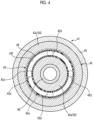
- Fig. 4 is a diagram showing an example of the solenoid device 41 shown in Fig. 3 as viewed from the tip end side.
- the recessed portion 43f has an annular shape centered on the central axis AX as viewed from the axial direction of the central axis AX.
- the recessed portion 43f is provided over one circumference in an axis-surrounding direction of the central axis AX.
- the recessed portion 43f is disposed at a position that overlaps a through-hole 42d of the valve unit 42, which will be described later, as viewed from the axial direction of the central axis AX.
- Figs. 5 to 7 are diagrams showing examples of a cross-sectional configuration of the recessed portion 43f.
- the recessed portion 43f may be formed in a state where both sides of the sealing portion 49 in the radial direction are left. According to this configuration, the space section 43e can be more reliably sealed on both sides of the sealing portion 49 in the radial direction.
- the recessed portion 43f may be formed to have a uniform depth over the entire radial direction. According to this configuration, in an end surface on the tip end side of the core 43, a sufficient area of the recessed portion 43f can be secured as viewed from the axial direction of the central axis AX. Further, as shown in Fig.
- the core 43 may have a configuration in which the core 43 has a chamfered section 43g at an end portion of the space section 43e on a tip end side in the axial direction of the central axis AX.
- the chamfered section 43g is provided on an outer peripheral side of the tubular portion 43a and on an inner peripheral side of the side surface part 43c, respectively.
- Each of the chamfered sections 43g has a tapered shape that is inclined toward the base end side toward the space section 43e side.
- the coil 44 is disposed in a state of being wound around the tubular portion 43a.
- the coil 44 penetrates the casing 45, which will be described later, and is connected to a power source part (not shown).
- the solenoid device 41 generates an electromagnetic force by causing a current to flow through the coil 44.
- the casing 45 accommodates the core 43 and the coil 44.
- the casing 45 is formed using, for example, a resin material.
- the casing 45 has a supporting part 45a that supports an elastic member 48 to be described later.
- the terminal fixing member 47 is disposed between the core 43 and the casing 45, which will be described later, in the axial direction of the central axis AX, and fixes a terminal 44a connected to the coil 44.
- the terminal 44a penetrates the casing 45 and is drawn out to an outside.
- the terminal fixing member 47 is formed using, for example, a resin material or the like.
- the tubular member 46 is disposed on an inner peripheral side of the core 43.
- the tubular member 46 is formed using, for example, a metallic material.
- the tubular member 46 may be metal that is a non-magnetic body.
- the tubular member 46 has, for example, a cylindrical shape, and is disposed such that a central axis thereof coincides with the central axis AX of the fuel injection valve 13.
- the tubular member 46 is disposed at a position where an end surface 46b on a tip end side comes into contact with the valve unit 42. In the present embodiment, the end surface 46b is flush with, for example, a tip end side end surface of the side surface part 43c of the core 43 and the tip end side end surface of the sealing portion 49.
- the elastic member 48 is accommodated on an inner peripheral side of the tubular member 46 in a state where an end portion on a base end side is supported by the supporting part 45a of the casing 45.
- the elastic member 48 applies an elastic force to the valve unit 42 toward a tip end side in the axial direction of the central axis AX.
- the valve unit 42 moves in the axial direction of the central axis AX by an electromagnetic force generated by the solenoid device 41.
- the valve unit 42 has an armature 42a, a valve body 42b, a stepped portion 42c, and a through-hole 42d.
- the armature 42a is formed using a magnetic body.
- the armature 42a has, for example, a disk shape.
- the armature 42a is disposed to oppose the end portion on the tip end side of the core 43 of the solenoid device 41.
- the valve body 42b extends from the armature 42a toward a tip end side.
- the valve body 42b is formed in a shape such that a tip portion thereof can close the fuel discharge port 31.
- the valve body 42b may be formed of a magnetic body or a non-magnetic body.
- the through-hole 42d is provided to penetrate the armature 42a in the axial direction of the central axis AX.
- the through-holes 42d are disposed with intervals in the axis-surrounding direction of the central axis AX as viewed from the axial direction of the central axis AX.
- a case where the through-holes 42d are disposed at 90° intervals around the central axis AX is given as an example, but the present embodiment is not limited to this configuration.
- FIG. 8 is a vertical sectional view showing an example of operation of the solenoid valve 40.
- Fig. 8 shows an example in a case where a current is passed through the coil 44.
- the armature 42a is pulled toward a core 43 side by the electromagnetic force, and the valve body 42b is separated from the fuel discharge port 31.
- the fuel discharge port 31 is in an open state.
- the pressure of the control-side pressure chamber 28 is reduced.
- the piston valve 22 moves to the control-side pressure chamber 28 side.
- the valve body 22d of the piston valve 22 is separated from the fuel injection port 30, and the fuel injection port 30 is in an open state.
- the fuel injection port 30 is in an open state, the fuel that has flowed from the fuel inflow port 24 into the injection-side pressure chamber 27 through the injection-side flow path 25 is injected from the fuel injection port 30.
- the stepped portion 42c of the valve unit 42 comes into contact with the end surface 46b of the tubular member 46, as shown in Fig. 8 .
- the tubular member 46 functions as a stopper that restricts movement of the valve unit 42 toward the base end side.
- the electromagnetic force of the solenoid device 41 is turned off so that the valve unit 42 is pressed by the elastic force of the elastic member 48 toward the tip end side in the axial direction of the central axis AX and is separated from the core 43, and the valve body 42b seals the fuel discharge port 31.
- the recessed portion 43f is provided on the end surface on the tip end side of the core 43, a region in which fuel can be disposed is secured between the core 43 and the valve unit 42. Since the region is provided, when the valve unit 42 moves in a direction away from the core 43, occurrence of cavitation is suppressed, and thus damage to the core 43 due to cavitation is suppressed.
- the solenoid device 41 is the solenoid device 41 that drives the valve unit 42 of the solenoid valve 40 provided to the fuel injection device 10 by an electromagnetic force, and includes the core 43 formed in a tubular shape and having the opposing surface 43h that opposes the valve unit 42, the coil 44 wound around the core 43, and the recessed portion 43f provided in the opposing surface 43h of the core 43 at a position that overlaps with the valve unit 42 as viewed from the axial direction of the central axis AX of the core 43.
- the recessed portion 43f is provided on the end surface on the tip end side of the core 43, a region in which fuel can be disposed is secured between the core 43 and the valve unit 42. Since the region is provided, for example, when the valve unit 42 moves in a direction away from the core 43, occurrence of cavitation is suppressed, and thus damage to the core 43 due to cavitation is suppressed. Accordingly, it is possible to provide the solenoid device 41 that is excellent in cavitation wear resistance and can maintain reliability of operation.
- the recessed portion 43f has an annular shape centered on the central axis AX as viewed from the axial direction of the central axis AX. According to this configuration, since a region in which fuel can be disposed can be secured over the entire axial direction of the central axis AX, occurrence of cavitation can be more reliably suppressed.
- the core 43 includes the magnetic body portion 50 that is formed using a magnetic body, is open to the valve unit 42 side, accommodates the coil 44, and includes the annular space section 43e as viewed from the axial direction, and the sealing portion 49 that is formed using a resin material and seals the space section 43e, and the recessed portion 43f is provided at the sealing portion 49.
- the recessed portion 43f is provided in a part of the core 43 that does not affect the generation of an electromagnetic force, occurrence of cavitation can be suppressed without lowering drivability of the valve unit 42.
- the magnetic body portion 50 includes the chamfered section 43g at the end portion of the space section 43e on the valve unit 42 side in the axial direction. According to this configuration, occurrence of cavitation can be more reliably suppressed.
- the solenoid valve 40 of the fuel injection device 10 includes the solenoid device 41 described above, and the valve unit 42 that is formed using a magnetic body, that is disposed to oppose the opposing surface 43h of the core 43, to which an elastic force is applied in the direction away from the core 43 in the axial direction, that presses, in a case where an electromagnetic force is not generated in the solenoid device 41, a fuel flow passage by the elastic force to close the flow passage, and that opens, in a case where an electromagnetic force is generated in the solenoid device 41, the flow passage by being pulled toward the core 43 to a position, at which the valve unit 42 comes into contact with the opposing surface 43h, to be separated from the flow passage by the electromagnetic force.
- the solenoid device 41 which can suppress damage to the core 43 due to cavitation and can maintain reliability of operation by suppressing occurrence of cavitation during driving of the valve unit 42, is included, it is possible to obtain the solenoid valve 40, for example, having a long life.
- the valve unit 42 includes the armature 42a that opposes the opposing surface 43h, the valve body 42b that extends from the armature 42a in the axial direction, the armature 42a includes the through-hole 42d that penetrates the armature 42a in the axial direction, and the recessed portion 43f is disposed at a position that overlaps with the through-hole 42d as viewed from the axial direction.
- the recessed portion 43f communicates with the tip end side of the valve unit 42 via the through-hole 42d, it is possible to more reliably suppress occurrence of cavitation when the valve unit 42 moves.
- the technical scope of the present invention is not limited to the embodiment described above, and can be appropriately changed without departing from the scope of the present invention.
- the configuration in which the solenoid valve 40 is provided in the fuel injection valve 13 of the fuel injection device 10 has been described as an example, but the present invention is not limited thereto.
- the solenoid valve 40 may be provided at another portion of the fuel injection device 10.
- a form of the fuel injection device 10 and a form of the fuel pump 11 are not limited to the embodiment described above.
- the number of the common rail 12 and the fuel injection valves 13, a connection position of the fuel pump 11, and the like can be appropriately set.
Landscapes
- Engineering & Computer Science (AREA)
- General Engineering & Computer Science (AREA)
- Mechanical Engineering (AREA)
- Physics & Mathematics (AREA)
- Electromagnetism (AREA)
- Chemical & Material Sciences (AREA)
- Combustion & Propulsion (AREA)
- Fluid Mechanics (AREA)
- Fuel-Injection Apparatus (AREA)
- Magnetically Actuated Valves (AREA)
Abstract
Description
- The present disclosure relates to a solenoid device and a solenoid valve of a fuel injection device.
- A common rail type fuel injection device applied to a diesel engine or the like includes a fuel pump, a common rail, and a fuel injection valve. The fuel pump sucks fuel from a fuel tank, pressurizes the fuel, and supplies the fuel to the common rail as high-pressure fuel. The common rail maintains the high-pressure fuel supplied from the fuel pump at a predetermined pressure. The fuel injection valve opens and closes an injection valve to inject the high-pressure fuel from the common rail into a combustion chamber of the diesel engine.
- The fuel injection valve has, for example, a solenoid valve having a solenoid device that generates an electromagnetic force by causing a current to flow through a coil wound around a core, and a valve unit formed using a magnetic body. In such a solenoid valve, for example, a configuration in which a fuel flow path is pressed by causing an elastic force to act on the valve unit is made, and in a case where an electromagnetic force is not generated by the solenoid device, the fuel flow path is pressed to be closed by the elastic force. Further, in a case where an electromagnetic force is generated by the solenoid device, the valve unit is pulled toward a core side of the solenoid device by the electromagnetic force, and the valve unit is separated from the flow path to cause the flow path to be in an open state (for example, refer to PTL 1 and the like).
- [PTL 1]
Japanese Unexamined Patent Application Publication No. 2010-101349 - In the solenoid valve as described above, for example, when the valve unit separates from the core, a negative pressure temporarily occurs in a gap between the valve unit and the core, and cavitation may occur. The cavitation collapses when a pressure in the gap between the valve unit and the core is restored, and damages a part of the core. For this reason, for example, if the solenoid device is operated for a long period of time, reliability of operation may decrease.
- The present disclosure has been made in view of the above, and an object of the present disclosure is to provide a solenoid device and a solenoid valve of a fuel injection device that are excellent in cavitation wear resistance and can maintain reliability of operation.
- A solenoid device according to the present disclosure is a solenoid device that drives a valve unit of a solenoid valve provided to a fuel injection device by an electromagnetic force, the solenoid device includes a core formed in a tubular shape and having an opposing surface that opposes the valve unit, a coil wound around the core; and a recessed portion provided in the opposing surface of the core at a position that overlaps with the valve unit as viewed from an axial direction of a central axis of the core.
- A solenoid valve of a fuel injection device according to the present disclosure includes the solenoid device described above, and a valve unit that is formed using a magnetic body, that is disposed to oppose the opposing surface of the core, to which an elastic force is applied in a direction away from the core in the axial direction, that presses, in a case where an electromagnetic force is not generated in the solenoid device, a fuel flow passage by the elastic force to close the flow passage, and that opens, in a case where an electromagnetic force is generated in the solenoid device, the flow passage by being pulled toward the core to a position, at which the valve unit comes into contact with the opposing surface, to be separated from the flow passage by the electromagnetic force.
- According to the present disclosure, it is possible to provide a solenoid device and a solenoid valve of a fuel injection device that are excellent in cavitation wear resistance and can maintain reliability of operation.
-
-
Fig. 1 is a schematic configuration diagram showing an example of a fuel injection device of the present embodiment. -
Fig. 2 is a vertical sectional view showing an example of a fuel injection valve. -
Fig. 3 is a vertical sectional view showing an example of a solenoid valve. -
Fig. 4 is a diagram showing an example of a solenoid device shown inFig. 3 as viewed from a tip end side. -
Fig. 5 is a diagram showing an example of a cross-sectional configuration of a recessed portion. -
Fig. 6 is a diagram showing an example of a cross-sectional configuration of a recessed portion. -
Fig. 7 is a diagram showing an example of a cross-sectional configuration of a recessed portion. -
Fig. 8 is a vertical sectional view showing an example of operation of the solenoid valve. - Hereinafter, an embodiment of a solenoid device and a solenoid valve of a fuel injection device according to the present disclosure will be described with reference to the drawings. The invention is not limited to the embodiment. Further, components in the following embodiment include components that can be easily replaced by those skilled in the art or components that are substantially the same.
-
Fig. 1 is a schematic configuration diagram showing an example of afuel injection device 10 of the present embodiment. As shown inFig. 1 , thefuel injection device 10 is installed in a diesel engine (internal combustion engine) . Thefuel injection device 10 includes afuel pump 11, acommon rail 12, and a plurality offuel injection valves 13. - A
fuel tank 14 is connected to thefuel pump 11 via a fuel line L11. Thefuel pump 11 sucks fuel stored in thefuel tank 14 from the fuel line L11 and pressurizes the fuel to generate high-pressure fuel. Acommon rail 12 is connected to thefuel pump 11 via a fuel high-pressure line L12. Thecommon rail 12 maintains the high-pressure fuel supplied from thefuel pump 11 at a predetermined pressure. Thefuel injection valves 13 are respectively connected to thecommon rail 12 via a plurality of (four in the present embodiment) fuel supply lines L13. Thefuel injection valve 13 opens and closes a solenoid valve to inject the high-pressure fuel of thecommon rail 12 into each cylinder (combustion chamber) of the diesel engine. -
Fig. 2 is a vertical sectional view showing an example of thefuel injection valve 13. As shown inFig. 2 , thefuel injection valve 13 has a shape extending in an axial direction of a central axis AX, and has aninjection unit 20 and asolenoid valve 40. Hereinafter, in describing a configuration of thefuel injection valve 13, afuel injection port 30 side in the axial direction of the central axis AX will be referred to as a tip end side, and asolenoid valve 40 side will be referred to as a base end side. - The
injection unit 20 has acasing 21 and a piston valve 22. Thecasing 21 includes afuel inflow port 24, an injection-side flow path 25, a control-side flow path 26, an injection-side pressure chamber 27, a control-side pressure chamber 28, acylinder chamber 29, afuel injection port 30, afuel discharge port 31, and a solenoid valve-side pressure chamber 32. - The fuel from the fuel supply line L13 flows into the
fuel inflow port 24. The injection-side flow path 25 connects thefuel inflow port 24 and the injection-side pressure chamber 27. The control-side flow path 26 connects thefuel inflow port 24 and the control-side pressure chamber 28. - The injection-
side pressure chamber 27 is connected to thefuel injection port 30. Thefuel injection port 30 is disposed at an end portion on a tip end side of thecasing 21, and jets fuel toward each cylinder of the diesel engine. - The control-
side pressure chamber 28 is connected to thefuel discharge port 31. Thefuel discharge port 31 is disposed at an end portion on a base end side of thecasing 21, and is connected to the solenoid valve-side pressure chamber 32. The solenoid valve-side pressure chamber 32 is connected to the solenoid valve 40 (aspace section 46d to be described later). - The
cylinder chamber 29 is connected to the injection-side pressure chamber 27 and the control-side pressure chamber 28. Thecylinder chamber 29 accommodates the piston valve 22. Thecylinder chamber 29 is connected to the solenoid valve-side pressure chamber 32 via aflow path 29a. - The piston valve 22 is accommodated in the
cylinder chamber 29 and is provided to be movable toward an injection-side pressure chamber 27 side or a control-side pressure chamber 28 side. The piston valve 22 has aspring seat member 22a, a control-side piston member 22b, a connectingmember 22c, and avalve body 22d. Thespring seat member 22a, the control-side piston member 22b, and the connectingmember 22c are integrated. Thespring seat member 22a receives an elastic force of anelastic member 23 to be described later. The control-side piston member 22b receives a pressure of the control-side pressure chamber 28. The connectingmember 22c connects thespring seat member 22a and the control-side piston member 22b. Thevalve body 22d protrudes from thespring seat member 22a toward the tip end side in the axial direction of the central axis AX. Thevalve body 22d comes into contact with thespring seat member 22a by a resultant force of a receiving pressure from each pressure chamber and the elastic force. Thevalve body 22d is formed in a shape such that a tip portion thereof can close thefuel injection port 30. Thevalve body 22d receives a pressure of the injection-side pressure chamber 27. - In a case where the pressure of the injection-
side pressure chamber 27 is smaller than a resultant force of the pressure of the control-side pressure chamber 28 and the elastic force of theelastic member 23, the piston valve 22 is in a state of being pressed toward the injection-side pressure chamber 27 side. In this case, thefuel injection port 30 is in a state of being closed by thevalve body 22d. From this state, in a case where the pressure of the injection-side pressure chamber 27 becomes larger than the resultant force of the pressure of the control-side pressure chamber 28 and the elastic force of theelastic member 23, the piston valve 22 is in a state of being pressed toward the control-side pressure chamber 28 side. In this case, thevalve body 22d is separated from thefuel injection port 30, and thefuel injection port 30 is in an open state. - The
solenoid valve 40 has asolenoid device 41 and avalve unit 42.Fig. 3 is a vertical sectional view showing an example of thesolenoid valve 40.Fig. 3 shows a part ofFig. 2 in an enlarged scale. As shown inFig. 3 , thesolenoid device 41 drives thevalve unit 42 along the axial direction of the central axis AX by an electromagnetic force. Thesolenoid device 41 includes a core 43, acoil 44, acasing 45, atubular member 46, and aterminal fixing member 47. - The
core 43 has amagnetic body portion 50 and a sealingportion 49. Themagnetic body portion 50 has atubular portion 43a, aflange portion 43b, and aside surface part 43c. Thetubular portion 43a is formed, for example, in a cylindrical shape. Theflange portion 43b has, for example, a disk shape and is disposed on a base end side of thecore 43. Each of thetubular portion 43a and theflange portion 43b is disposed such that each central axis thereof coincides with the central axis AX of thefuel injection valve 13. - The
side surface part 43c has a cylindrical shape that involves thetubular portion 43a. Theside surface part 43c is disposed with an interval in a radial direction from thetubular portion 43a and extends toward a tip end side. Thetubular portion 43a, theflange portion 43b, and theside surface part 43c are formed using a magnetic body (magnetic body portion 50). Thecore 43 accommodates thecoil 44 in aspace section 43e surrounded by atubular portion 43a, aflange portion 43b, and aside surface part 43c. That is, thetubular portion 43a, theflange portion 43b, and theside surface part 43c constitute themagnetic body portion 50 that is open to avalve unit 42 side, accommodates thecoil 44, and has theannular space section 43e as viewed from the axial direction of the central axis AX. When viewed as a single body, thecore 43 is provided with thespace section 43e, but is actually in a state where thecoil 44 is disposed. Thespace section 43e in which thecoil 44 is disposed is sealed by the sealingportion 49. The sealingportion 49 is formed using, for example, a resin material. Thecore 43 has an opposingsurface 43h, which will be described later, opposing thevalve unit 42. The opposingsurface 43h is disposed at an end portion on a tip end side of thecore 43. In the present embodiment, an end portion on a tip end side of thetubular portion 43a, an end portion on a tip end side of theside surface part 43c, and an end portion on a tip end side of the sealingportion 49 constitute the opposingsurface 43h. - The sealing
portion 49 has a recessedportion 43f on an end surface on the tip end side. The recessedportion 43f is formed in a state where a part of the sealingportion 49 is recessed toward the base end side.Fig. 4 is a diagram showing an example of thesolenoid device 41 shown inFig. 3 as viewed from the tip end side. As shown inFig. 4 , the recessedportion 43f has an annular shape centered on the central axis AX as viewed from the axial direction of the central axis AX. The recessedportion 43f is provided over one circumference in an axis-surrounding direction of the central axis AX. The recessedportion 43f is disposed at a position that overlaps a through-hole 42d of thevalve unit 42, which will be described later, as viewed from the axial direction of the central axis AX. -
Figs. 5 to 7 are diagrams showing examples of a cross-sectional configuration of the recessedportion 43f. As shown inFig. 5 , the recessedportion 43f may be formed in a state where both sides of the sealingportion 49 in the radial direction are left. According to this configuration, thespace section 43e can be more reliably sealed on both sides of the sealingportion 49 in the radial direction. In addition, as shown inFig. 6 , the recessedportion 43f may be formed to have a uniform depth over the entire radial direction. According to this configuration, in an end surface on the tip end side of the core 43, a sufficient area of the recessedportion 43f can be secured as viewed from the axial direction of the central axis AX. Further, as shown inFig. 7 , in addition to the configuration ofFig. 6 , thecore 43 may have a configuration in which thecore 43 has a chamferedsection 43g at an end portion of thespace section 43e on a tip end side in the axial direction of the central axis AX. The chamferedsection 43g is provided on an outer peripheral side of thetubular portion 43a and on an inner peripheral side of theside surface part 43c, respectively. Each of the chamferedsections 43g has a tapered shape that is inclined toward the base end side toward thespace section 43e side. - As shown in
Fig. 3 , thecoil 44 is disposed in a state of being wound around thetubular portion 43a. Thecoil 44 penetrates thecasing 45, which will be described later, and is connected to a power source part (not shown). Thesolenoid device 41 generates an electromagnetic force by causing a current to flow through thecoil 44. - The
casing 45 accommodates thecore 43 and thecoil 44. Thecasing 45 is formed using, for example, a resin material. Thecasing 45 has a supporting part 45a that supports anelastic member 48 to be described later. Further, theterminal fixing member 47 is disposed between the core 43 and thecasing 45, which will be described later, in the axial direction of the central axis AX, and fixes a terminal 44a connected to thecoil 44. The terminal 44a penetrates thecasing 45 and is drawn out to an outside. Theterminal fixing member 47 is formed using, for example, a resin material or the like. - The
tubular member 46 is disposed on an inner peripheral side of thecore 43. Thetubular member 46 is formed using, for example, a metallic material. Thetubular member 46 may be metal that is a non-magnetic body. Thetubular member 46 has, for example, a cylindrical shape, and is disposed such that a central axis thereof coincides with the central axis AX of thefuel injection valve 13. Thetubular member 46 is disposed at a position where anend surface 46b on a tip end side comes into contact with thevalve unit 42. In the present embodiment, theend surface 46b is flush with, for example, a tip end side end surface of theside surface part 43c of thecore 43 and the tip end side end surface of the sealingportion 49. - The
elastic member 48 is accommodated on an inner peripheral side of thetubular member 46 in a state where an end portion on a base end side is supported by the supporting part 45a of thecasing 45. Theelastic member 48 applies an elastic force to thevalve unit 42 toward a tip end side in the axial direction of the central axis AX. - The
valve unit 42 moves in the axial direction of the central axis AX by an electromagnetic force generated by thesolenoid device 41. Thevalve unit 42 has anarmature 42a, avalve body 42b, a steppedportion 42c, and a through-hole 42d. Thearmature 42a is formed using a magnetic body. Thearmature 42a has, for example, a disk shape. Thearmature 42a is disposed to oppose the end portion on the tip end side of thecore 43 of thesolenoid device 41. Thevalve body 42b extends from thearmature 42a toward a tip end side. Thevalve body 42b is formed in a shape such that a tip portion thereof can close thefuel discharge port 31. Thevalve body 42b may be formed of a magnetic body or a non-magnetic body. - The through-
hole 42d is provided to penetrate thearmature 42a in the axial direction of the central axis AX. The through-holes 42d are disposed with intervals in the axis-surrounding direction of the central axis AX as viewed from the axial direction of the central axis AX. In the present embodiment, as shown by the one-point chain line inFig. 4 , for example, a case where the through-holes 42d are disposed at 90° intervals around the central axis AX is given as an example, but the present embodiment is not limited to this configuration. - Operation of the
fuel injection valve 13 configured as described above will be described. In a case where no current is passed through thecoil 44 of thesolenoid device 41, no electromagnetic force is generated in thesolenoid device 41. In this case, in thevalve unit 42, thevalve body 42b presses thefuel discharge port 31 toward the tip end side by the elastic force of theelastic member 48. As a result, thefuel discharge port 31 is in a closed state. - In a state where the
fuel discharge port 31 is in a closed state, the resultant force of the receiving pressure of the control-side pressure chamber 28 and the elastic force of theelastic member 23 becomes larger than the receiving pressure of the injection-side pressure chamber 27. Therefore, the piston valve 22 presses thefuel injection port 30 to close thefuel injection port 30. - Further, in a case where a current is passed through the
coil 44 of thesolenoid device 41, an electromagnetic force is generated in thesolenoid device 41.Fig. 8 is a vertical sectional view showing an example of operation of thesolenoid valve 40.Fig. 8 shows an example in a case where a current is passed through thecoil 44. As shown inFig. 8 , in a case where an electromagnetic force is generated in thesolenoid device 41, in thevalve unit 42, thearmature 42a is pulled toward a core 43 side by the electromagnetic force, and thevalve body 42b is separated from thefuel discharge port 31. As a result, thefuel discharge port 31 is in an open state. - By opening the
fuel discharge port 31, the pressure of the control-side pressure chamber 28 is reduced. In a case where the resultant force of the receiving pressure of the control-side pressure chamber 28 and the elastic force of theelastic member 23 becomes smaller than the receiving pressure of the injection-side pressure chamber 27, the piston valve 22 moves to the control-side pressure chamber 28 side. In this case, thevalve body 22d of the piston valve 22 is separated from thefuel injection port 30, and thefuel injection port 30 is in an open state. In a case where thefuel injection port 30 is in an open state, the fuel that has flowed from thefuel inflow port 24 into the injection-side pressure chamber 27 through the injection-side flow path 25 is injected from thefuel injection port 30. - In the above operation, in a case where the
valve unit 42 is pulled toward the core 43 side by the electromagnetic force of thesolenoid device 41, the steppedportion 42c of thevalve unit 42 comes into contact with theend surface 46b of thetubular member 46, as shown inFig. 8 . In this case, thetubular member 46 functions as a stopper that restricts movement of thevalve unit 42 toward the base end side. - After the stepped
portion 42c of thevalve unit 42 comes into contact with theend surface 46b of thetubular member 46, the electromagnetic force of thesolenoid device 41 is turned off so that thevalve unit 42 is pressed by the elastic force of theelastic member 48 toward the tip end side in the axial direction of the central axis AX and is separated from thecore 43, and thevalve body 42b seals thefuel discharge port 31. In the present embodiment, since the recessedportion 43f is provided on the end surface on the tip end side of the core 43, a region in which fuel can be disposed is secured between the core 43 and thevalve unit 42. Since the region is provided, when thevalve unit 42 moves in a direction away from thecore 43, occurrence of cavitation is suppressed, and thus damage to thecore 43 due to cavitation is suppressed. - As described above, the
solenoid device 41 according to the present embodiment is thesolenoid device 41 that drives thevalve unit 42 of thesolenoid valve 40 provided to thefuel injection device 10 by an electromagnetic force, and includes the core 43 formed in a tubular shape and having the opposingsurface 43h that opposes thevalve unit 42, thecoil 44 wound around thecore 43, and the recessedportion 43f provided in the opposingsurface 43h of the core 43 at a position that overlaps with thevalve unit 42 as viewed from the axial direction of the central axis AX of thecore 43. - According to this configuration, since the recessed
portion 43f is provided on the end surface on the tip end side of the core 43, a region in which fuel can be disposed is secured between the core 43 and thevalve unit 42. Since the region is provided, for example, when thevalve unit 42 moves in a direction away from thecore 43, occurrence of cavitation is suppressed, and thus damage to thecore 43 due to cavitation is suppressed. Accordingly, it is possible to provide thesolenoid device 41 that is excellent in cavitation wear resistance and can maintain reliability of operation. - In the
solenoid device 41 according to the present embodiment, the recessedportion 43f has an annular shape centered on the central axis AX as viewed from the axial direction of the central axis AX. According to this configuration, since a region in which fuel can be disposed can be secured over the entire axial direction of the central axis AX, occurrence of cavitation can be more reliably suppressed. - In the
solenoid device 41 according to the present embodiment, thecore 43 includes themagnetic body portion 50 that is formed using a magnetic body, is open to thevalve unit 42 side, accommodates thecoil 44, and includes theannular space section 43e as viewed from the axial direction, and the sealingportion 49 that is formed using a resin material and seals thespace section 43e, and the recessedportion 43f is provided at the sealingportion 49. According to this configuration, since the recessedportion 43f is provided in a part of the core 43 that does not affect the generation of an electromagnetic force, occurrence of cavitation can be suppressed without lowering drivability of thevalve unit 42. - In the
solenoid device 41 according to the present embodiment, themagnetic body portion 50 includes the chamferedsection 43g at the end portion of thespace section 43e on thevalve unit 42 side in the axial direction. According to this configuration, occurrence of cavitation can be more reliably suppressed. - The
solenoid valve 40 of thefuel injection device 10 according to the present embodiment includes thesolenoid device 41 described above, and thevalve unit 42 that is formed using a magnetic body, that is disposed to oppose the opposingsurface 43h of the core 43, to which an elastic force is applied in the direction away from the core 43 in the axial direction, that presses, in a case where an electromagnetic force is not generated in thesolenoid device 41, a fuel flow passage by the elastic force to close the flow passage, and that opens, in a case where an electromagnetic force is generated in thesolenoid device 41, the flow passage by being pulled toward the core 43 to a position, at which thevalve unit 42 comes into contact with the opposingsurface 43h, to be separated from the flow passage by the electromagnetic force. - According to this configuration, since the
solenoid device 41, which can suppress damage to thecore 43 due to cavitation and can maintain reliability of operation by suppressing occurrence of cavitation during driving of thevalve unit 42, is included, it is possible to obtain thesolenoid valve 40, for example, having a long life. - In the
solenoid valve 40 of thefuel injection device 10 according to the present embodiment, thevalve unit 42 includes thearmature 42a that opposes the opposingsurface 43h, thevalve body 42b that extends from thearmature 42a in the axial direction, thearmature 42a includes the through-hole 42d that penetrates thearmature 42a in the axial direction, and the recessedportion 43f is disposed at a position that overlaps with the through-hole 42d as viewed from the axial direction. According to this configuration, since the recessedportion 43f communicates with the tip end side of thevalve unit 42 via the through-hole 42d, it is possible to more reliably suppress occurrence of cavitation when thevalve unit 42 moves. - The technical scope of the present invention is not limited to the embodiment described above, and can be appropriately changed without departing from the scope of the present invention. For example, in the embodiment described above, the configuration in which the
solenoid valve 40 is provided in thefuel injection valve 13 of thefuel injection device 10 has been described as an example, but the present invention is not limited thereto. Thesolenoid valve 40 may be provided at another portion of thefuel injection device 10. - Further, a form of the
fuel injection device 10 and a form of thefuel pump 11 are not limited to the embodiment described above. For example, the number of thecommon rail 12 and thefuel injection valves 13, a connection position of thefuel pump 11, and the like can be appropriately set. -
- 10 fuel injection device
- 11 fuel pump
- 12 common rail
- 13 fuel injection valve
- 14 fuel tank
- 20 injection unit
- 21, 45 casing
- 22 piston valve
- 22a spring seat member
- 22b control-side piston member
- 22c connecting member
- 22d, 42b valve body
- 23, 48 elastic member
- 24 fuel inflow port
- 25 injection-side flow path
- 26 control-side flow path
- 27 injection-side pressure chamber
- 28 control-side pressure chamber
- 29 cylinder chamber
- 30 fuel injection port
- 31 fuel discharge port
- 32 solenoid valve-side pressure chamber
- 40 solenoid valve
- 41 solenoid device
- 42 valve unit
- 42a armature
- 42c stepped portion
- 42d through-hole
- 43 core
- 43a tubular portion
- 43b flange portion
- 43c side surface part
- 43e space section
- 43g chamfered section
- 43h opposing surface
- 44 coil
- 45a supporting part
- 46 tubular member
- 46b end surface
- 47 terminal fixing member
- 49 sealing portion
- 43f recessed portion
- 50 magnetic body portion
- AX central axis
- L11 fuel line
- L12 fuel high-pressure line
- L13 fuel supply line
Claims (6)
- A solenoid device that drives a valve unit of a solenoid valve provided to a fuel injection device by an electromagnetic force, the solenoid device comprising:a core formed in a tubular shape and having an opposing surface that opposes the valve unit;a coil wound around the core; anda recessed portion provided in the opposing surface of the core at a position that overlaps with the valve unit as viewed from an axial direction of a central axis of the core.
- The solenoid device according to Claim 1,
wherein the recessed portion has an annular shape centered on the central axis as viewed from the axial direction. - The solenoid device according to Claim 1 or 2,wherein the core includes a magnetic body portion that is formed using a magnetic body, is open to a valve unit side, accommodates the coil, and includes an annular space section as viewed from the axial direction, and a sealing portion that is formed using a resin material and seals the space section, andthe recessed portion is provided at the sealing portion.
- The solenoid device according to Claim 3,
wherein the magnetic body portion includes a chamfered section at an end portion of the space section on the side of the valve unit in the axial direction. - A solenoid valve of a fuel injection device comprising:the solenoid device according to any one of Claims 1 to 4; anda valve unit that is formed using a magnetic body, that is disposed to oppose the opposing surface of the core, to which an elastic force is applied in a direction away from the core in the axial direction, that presses, in a case where an electromagnetic force is not generated in the solenoid device, a fuel flow passage by the elastic force to close the flow passage, and that opens, in a case where an electromagnetic force is generated in the solenoid device, the flow passage by being pulled toward the core to a position, at which the valve unit comes into contact with the opposing surface, to be separated from the flow passage by the electromagnetic force.
- The solenoid valve of the fuel injection device according to Claim 5,wherein the valve unit includes an armature that opposes the opposing surface, and a valve body that extends from the armature in the axial direction,the armature includes a through-hole that penetrates the armature in the axial direction, andthe recessed portion is disposed at a position that overlaps with the through-hole as viewed from the axial direction.
Applications Claiming Priority (2)
| Application Number | Priority Date | Filing Date | Title |
|---|---|---|---|
| JP2021122449A JP7770129B2 (en) | 2021-07-27 | 2021-07-27 | Solenoid device and solenoid valve of fuel injection device |
| PCT/JP2022/024917 WO2023007998A1 (en) | 2021-07-27 | 2022-06-22 | Solenoid device and solenoid valve of fuel injection device |
Publications (2)
| Publication Number | Publication Date |
|---|---|
| EP4343188A1 true EP4343188A1 (en) | 2024-03-27 |
| EP4343188A4 EP4343188A4 (en) | 2024-10-02 |
Family
ID=85086664
Family Applications (1)
| Application Number | Title | Priority Date | Filing Date |
|---|---|---|---|
| EP22849073.6A Pending EP4343188A4 (en) | 2021-07-27 | 2022-06-22 | SOLENOID DEVICE AND SOLENOID VALVE OF FUEL INJECTION DEVICE |
Country Status (6)
| Country | Link |
|---|---|
| US (1) | US20240254954A1 (en) |
| EP (1) | EP4343188A4 (en) |
| JP (1) | JP7770129B2 (en) |
| KR (1) | KR20240009455A (en) |
| CN (1) | CN117545917A (en) |
| WO (1) | WO2023007998A1 (en) |
Family Cites Families (15)
| Publication number | Priority date | Publication date | Assignee | Title |
|---|---|---|---|---|
| US4899935A (en) * | 1988-03-14 | 1990-02-13 | Yamaha Hatsudoki Kabushiki Kaisha | Valve support for accumulator type fuel injection nozzle |
| US5082180A (en) * | 1988-12-28 | 1992-01-21 | Diesel Kiki Co., Ltd. | Electromagnetic valve and unit fuel injector with electromagnetic valve |
| JPH04106575U (en) * | 1991-02-27 | 1992-09-14 | エヌオーケー株式会社 | solenoid |
| DE4428869C2 (en) * | 1993-08-06 | 1997-08-07 | Zexel Corp | magnetic valve |
| US6027037A (en) * | 1995-12-05 | 2000-02-22 | Denso Corporation | Accumulator fuel injection apparatus for internal combustion engine |
| JP2003269288A (en) | 2002-03-15 | 2003-09-25 | Bosch Automotive Systems Corp | Fuel injector |
| JP4022856B2 (en) | 2002-03-15 | 2007-12-19 | 株式会社デンソー | Electromagnetic actuator |
| JP4026592B2 (en) * | 2003-12-24 | 2007-12-26 | 株式会社デンソー | Fuel injection valve |
| JP2006194237A (en) * | 2004-12-14 | 2006-07-27 | Denso Corp | Electromagnetic actuator |
| JP2007064364A (en) * | 2005-08-31 | 2007-03-15 | Denso Corp | solenoid valve |
| JP4166796B2 (en) * | 2006-04-20 | 2008-10-15 | 三菱電機株式会社 | Electromagnetic fuel injection device |
| JP5101456B2 (en) * | 2008-10-21 | 2012-12-19 | 三菱重工業株式会社 | Solenoid solenoid valve device |
| JP6376988B2 (en) * | 2014-09-02 | 2018-08-22 | 株式会社デンソー | Fuel injection valve |
| JP6797085B2 (en) * | 2017-07-10 | 2020-12-09 | ヤンマーパワーテクノロジー株式会社 | Fuel injection pump |
| DE102019215119A1 (en) * | 2019-10-01 | 2021-04-01 | Robert Bosch Gmbh | Fuel injector |
-
2021
- 2021-07-27 JP JP2021122449A patent/JP7770129B2/en active Active
-
2022
- 2022-06-22 KR KR1020237043271A patent/KR20240009455A/en not_active Ceased
- 2022-06-22 US US18/570,980 patent/US20240254954A1/en active Pending
- 2022-06-22 EP EP22849073.6A patent/EP4343188A4/en active Pending
- 2022-06-22 CN CN202280044191.4A patent/CN117545917A/en active Pending
- 2022-06-22 WO PCT/JP2022/024917 patent/WO2023007998A1/en not_active Ceased
Also Published As
| Publication number | Publication date |
|---|---|
| KR20240009455A (en) | 2024-01-22 |
| JP2023018371A (en) | 2023-02-08 |
| US20240254954A1 (en) | 2024-08-01 |
| EP4343188A4 (en) | 2024-10-02 |
| WO2023007998A1 (en) | 2023-02-02 |
| CN117545917A (en) | 2024-02-09 |
| JP7770129B2 (en) | 2025-11-14 |
Similar Documents
| Publication | Publication Date | Title |
|---|---|---|
| EP3315760B1 (en) | Flow rate control valve and high-pressure fuel supply pump | |
| US9828957B2 (en) | Fuel injector and method for manufacturing fuel injector | |
| JP2007205234A (en) | Fuel injection valve | |
| CN111373139A (en) | High pressure fuel pump | |
| EP1967729B1 (en) | An electromagnetic valve for the dosage of fuel in an internal combustion engine | |
| EP4343188A1 (en) | Solenoid device and solenoid valve of fuel injection device | |
| JP4120632B2 (en) | Fuel injection valve | |
| CN110651117A (en) | Electromagnetic valve, electromagnetic suction valve mechanism, and high-pressure fuel pump | |
| US20170016417A1 (en) | Fuel injection device | |
| JP4577654B2 (en) | Electromagnetic drive device and fuel injection valve using the same | |
| JP2009281346A (en) | Fuel injection device | |
| JP5093212B2 (en) | Fuel injection valve | |
| EP4343189A1 (en) | Solenoid device and solenoid valve of fuel injection device | |
| CN113175402B (en) | Solenoid Fuel Injection Valve | |
| JP2007154855A (en) | Fuel injection valve | |
| CN112955643B (en) | Solenoid mechanism and high-pressure fuel pump | |
| EP4339446A1 (en) | Fuel injection valve, and method for driving fuel injection valve | |
| CN108779747B (en) | fuel injection device | |
| CN120712404A (en) | Electromagnetic actuator and fuel injection device | |
| EP4671524A1 (en) | FUEL INJECTION DEVICE | |
| JP2005083201A (en) | Fuel injection valve | |
| CN119173688A (en) | Solenoid valve mechanism and fuel pump | |
| CN117321300A (en) | Solenoid fuel injection valve |
Legal Events
| Date | Code | Title | Description |
|---|---|---|---|
| STAA | Information on the status of an ep patent application or granted ep patent |
Free format text: STATUS: THE INTERNATIONAL PUBLICATION HAS BEEN MADE |
|
| PUAI | Public reference made under article 153(3) epc to a published international application that has entered the european phase |
Free format text: ORIGINAL CODE: 0009012 |
|
| STAA | Information on the status of an ep patent application or granted ep patent |
Free format text: STATUS: REQUEST FOR EXAMINATION WAS MADE |
|
| 17P | Request for examination filed |
Effective date: 20231219 |
|
| AK | Designated contracting states |
Kind code of ref document: A1 Designated state(s): AL AT BE BG CH CY CZ DE DK EE ES FI FR GB GR HR HU IE IS IT LI LT LU LV MC MK MT NL NO PL PT RO RS SE SI SK SM TR |
|
| A4 | Supplementary search report drawn up and despatched |
Effective date: 20240830 |
|
| RIC1 | Information provided on ipc code assigned before grant |
Ipc: F02M 63/00 20060101ALI20240826BHEP Ipc: F02M 47/02 20060101ALI20240826BHEP Ipc: F02M 51/06 20060101ALI20240826BHEP Ipc: F16K 31/06 20060101AFI20240826BHEP |
|
| DAV | Request for validation of the european patent (deleted) | ||
| DAX | Request for extension of the european patent (deleted) |