EP4343177A1 - Centrifugal compensation control method, apparatus and system for transmission, and storage medium and vehicle - Google Patents
Centrifugal compensation control method, apparatus and system for transmission, and storage medium and vehicle Download PDFInfo
- Publication number
- EP4343177A1 EP4343177A1 EP22824153.5A EP22824153A EP4343177A1 EP 4343177 A1 EP4343177 A1 EP 4343177A1 EP 22824153 A EP22824153 A EP 22824153A EP 4343177 A1 EP4343177 A1 EP 4343177A1
- Authority
- EP
- European Patent Office
- Prior art keywords
- signal
- vehicle
- status
- condition
- centrifugal compensation
- Prior art date
- Legal status (The legal status is an assumption and is not a legal conclusion. Google has not performed a legal analysis and makes no representation as to the accuracy of the status listed.)
- Granted
Links
Images


Classifications
-
- F—MECHANICAL ENGINEERING; LIGHTING; HEATING; WEAPONS; BLASTING
- F16—ENGINEERING ELEMENTS AND UNITS; GENERAL MEASURES FOR PRODUCING AND MAINTAINING EFFECTIVE FUNCTIONING OF MACHINES OR INSTALLATIONS; THERMAL INSULATION IN GENERAL
- F16H—GEARING
- F16H63/00—Control outputs from the control unit to change-speed- or reversing-gearings for conveying rotary motion or to other devices than the final output mechanism
- F16H63/40—Control outputs from the control unit to change-speed- or reversing-gearings for conveying rotary motion or to other devices than the final output mechanism comprising signals other than signals for actuating the final output mechanisms
- F16H63/50—Signals to an engine or motor
- F16H63/502—Signals to an engine or motor for smoothing gear shifts
-
- F—MECHANICAL ENGINEERING; LIGHTING; HEATING; WEAPONS; BLASTING
- F16—ENGINEERING ELEMENTS AND UNITS; GENERAL MEASURES FOR PRODUCING AND MAINTAINING EFFECTIVE FUNCTIONING OF MACHINES OR INSTALLATIONS; THERMAL INSULATION IN GENERAL
- F16H—GEARING
- F16H61/00—Control functions within control units of change-speed- or reversing-gearings for conveying rotary motion ; Control of exclusively fluid gearing, friction gearing, gearings with endless flexible members or other particular types of gearing
- F16H61/02—Control functions within control units of change-speed- or reversing-gearings for conveying rotary motion ; Control of exclusively fluid gearing, friction gearing, gearings with endless flexible members or other particular types of gearing characterised by the signals used
- F16H61/0202—Control functions within control units of change-speed- or reversing-gearings for conveying rotary motion ; Control of exclusively fluid gearing, friction gearing, gearings with endless flexible members or other particular types of gearing characterised by the signals used the signals being electric
- F16H61/0204—Control functions within control units of change-speed- or reversing-gearings for conveying rotary motion ; Control of exclusively fluid gearing, friction gearing, gearings with endless flexible members or other particular types of gearing characterised by the signals used the signals being electric for gearshift control, e.g. control functions for performing shifting or generation of shift signal
- F16H61/0213—Control functions within control units of change-speed- or reversing-gearings for conveying rotary motion ; Control of exclusively fluid gearing, friction gearing, gearings with endless flexible members or other particular types of gearing characterised by the signals used the signals being electric for gearshift control, e.g. control functions for performing shifting or generation of shift signal characterised by the method for generating shift signals
-
- F—MECHANICAL ENGINEERING; LIGHTING; HEATING; WEAPONS; BLASTING
- F16—ENGINEERING ELEMENTS AND UNITS; GENERAL MEASURES FOR PRODUCING AND MAINTAINING EFFECTIVE FUNCTIONING OF MACHINES OR INSTALLATIONS; THERMAL INSULATION IN GENERAL
- F16H—GEARING
- F16H59/00—Control inputs to control units of change-speed- or reversing-gearings for conveying rotary motion
- F16H59/14—Inputs being a function of torque or torque demand
- F16H59/18—Inputs being a function of torque or torque demand dependent on the position of the accelerator pedal
-
- F—MECHANICAL ENGINEERING; LIGHTING; HEATING; WEAPONS; BLASTING
- F16—ENGINEERING ELEMENTS AND UNITS; GENERAL MEASURES FOR PRODUCING AND MAINTAINING EFFECTIVE FUNCTIONING OF MACHINES OR INSTALLATIONS; THERMAL INSULATION IN GENERAL
- F16H—GEARING
- F16H61/00—Control functions within control units of change-speed- or reversing-gearings for conveying rotary motion ; Control of exclusively fluid gearing, friction gearing, gearings with endless flexible members or other particular types of gearing
- F16H61/02—Control functions within control units of change-speed- or reversing-gearings for conveying rotary motion ; Control of exclusively fluid gearing, friction gearing, gearings with endless flexible members or other particular types of gearing characterised by the signals used
- F16H61/0262—Control functions within control units of change-speed- or reversing-gearings for conveying rotary motion ; Control of exclusively fluid gearing, friction gearing, gearings with endless flexible members or other particular types of gearing characterised by the signals used the signals being hydraulic
-
- F—MECHANICAL ENGINEERING; LIGHTING; HEATING; WEAPONS; BLASTING
- F16—ENGINEERING ELEMENTS AND UNITS; GENERAL MEASURES FOR PRODUCING AND MAINTAINING EFFECTIVE FUNCTIONING OF MACHINES OR INSTALLATIONS; THERMAL INSULATION IN GENERAL
- F16H—GEARING
- F16H61/00—Control functions within control units of change-speed- or reversing-gearings for conveying rotary motion ; Control of exclusively fluid gearing, friction gearing, gearings with endless flexible members or other particular types of gearing
- F16H61/04—Smoothing ratio shift
-
- F—MECHANICAL ENGINEERING; LIGHTING; HEATING; WEAPONS; BLASTING
- F16—ENGINEERING ELEMENTS AND UNITS; GENERAL MEASURES FOR PRODUCING AND MAINTAINING EFFECTIVE FUNCTIONING OF MACHINES OR INSTALLATIONS; THERMAL INSULATION IN GENERAL
- F16H—GEARING
- F16H59/00—Control inputs to control units of change-speed- or reversing-gearings for conveying rotary motion
- F16H59/68—Inputs being a function of gearing status
- F16H2059/683—Sensing pressure in control systems or in fluid-controlled devices, e.g. by pressure sensors
-
- F—MECHANICAL ENGINEERING; LIGHTING; HEATING; WEAPONS; BLASTING
- F16—ENGINEERING ELEMENTS AND UNITS; GENERAL MEASURES FOR PRODUCING AND MAINTAINING EFFECTIVE FUNCTIONING OF MACHINES OR INSTALLATIONS; THERMAL INSULATION IN GENERAL
- F16H—GEARING
- F16H59/00—Control inputs to control units of change-speed- or reversing-gearings for conveying rotary motion
- F16H59/36—Inputs being a function of speed
- F16H59/44—Inputs being a function of speed dependent on machine speed, e.g. the vehicle speed
-
- F—MECHANICAL ENGINEERING; LIGHTING; HEATING; WEAPONS; BLASTING
- F16—ENGINEERING ELEMENTS AND UNITS; GENERAL MEASURES FOR PRODUCING AND MAINTAINING EFFECTIVE FUNCTIONING OF MACHINES OR INSTALLATIONS; THERMAL INSULATION IN GENERAL
- F16H—GEARING
- F16H61/00—Control functions within control units of change-speed- or reversing-gearings for conveying rotary motion ; Control of exclusively fluid gearing, friction gearing, gearings with endless flexible members or other particular types of gearing
- F16H61/68—Control functions within control units of change-speed- or reversing-gearings for conveying rotary motion ; Control of exclusively fluid gearing, friction gearing, gearings with endless flexible members or other particular types of gearing specially adapted for stepped gearings
- F16H61/684—Control functions within control units of change-speed- or reversing-gearings for conveying rotary motion ; Control of exclusively fluid gearing, friction gearing, gearings with endless flexible members or other particular types of gearing specially adapted for stepped gearings without interruption of drive
- F16H61/688—Control functions within control units of change-speed- or reversing-gearings for conveying rotary motion ; Control of exclusively fluid gearing, friction gearing, gearings with endless flexible members or other particular types of gearing specially adapted for stepped gearings without interruption of drive with two inputs, e.g. selection of one of two torque-flow paths by clutches
Definitions
- the present application relates to the field of vehicle control technology, and in particular to a method, an apparatus and a system of centrifugal compensation control for a transmission, a storage medium, and a vehicle.
- the dual-clutch transmission is referred to as DCT.
- DCT The dual-clutch transmission
- a centrifugal compensation strategy is adopted in the DCT to optimize a shift operation of the DCT.
- the principal centrifugal compensation control strategy for the DCT is to centrifugally supplement a torque transmission pressure of the clutch by means of an engine speed and an actual pressure of the clutch.
- an abnormal noise may be generated by the DCT, which will affect the customer's experience.
- Embodiments of the present application provide a method of centrifugal compensation control for a transmission, an apparatus, a system, a storage medium, and a vehicle, which aim to address the problems existing in the above special circumstances.
- a method of centrifugal compensation control for a transmission includes that: collecting a vehicle working-condition signal and determining a vehicle condition status according to the vehicle working-condition signal; collecting a hydraulic module signal and determining a clutch oil-filling status according to the hydraulic module signal; and performing a centrifugal compensation on the transmission according to the vehicle condition status and the clutch oil-filling status.
- the vehicle working-condition signal includes an accelerator pedal signal, an ESP (Electronic Stability Program) signal, a gear signal and a vehicle speed signal.
- ESP Electronic Stability Program
- the vehicle condition status includes an in-situ large-throttle starting state, a large-throttle parking state, and a driving and gear-shifting state.
- the step of determining the vehicle condition status according to the vehicle working-condition signal includes that: Determining that the vehicle condition status is the in-situ large-throttle starting state in case that an opening-degree from the accelerator pedal signal is greater than a first opening-degree threshold, the gear signal is at a first gear, the ESP signal is a break-free or parking signal, and the vehicle speed signal has a first speed threshold.
- the vehicle condition status is the large-throttle parking state in case that the opening-degree from the accelerator pedal signal is greater than the first opening-degree threshold, the gear signal is at the first gear, the ESP signal is a braking or parking signal, and the vehicle speed signal has a second speed threshold.
- the vehicle condition status is the driving and gear-shifting state in case that the opening-degree from the accelerator pedal signal is greater than a second opening-degree threshold, the gear signal is at or above a second gear, the ESP signal is the brake-free or parking signal, and the vehicle speed signal has a third speed threshold.
- the hydraulic module signal includes a position signal of a piston and a position signal of a hydraulic valve plate.
- the clutch oil-filling status includes a status before a clutch is oil-filled and a status after the clutch is oil-filled.
- the step of determining the clutch oil-filling status according to the hydraulic module signal includes that: It is determined that the clutch oil-filling status is the status before the clutch is oil-filled in case that the position signal of the piston moves from a bottom dead center position toward a top dead center position and the position signal of the hydraulic valve plate is a switched-on signal.
- the clutch oil-filling status is the status after the clutch is oil-filled in case that the position signal of the piston moves from the top dead center position toward the bottom dead center position, and the position signal of the hydraulic valve plate is a switched-off signal.
- the step of performing the centrifugal compensation on the transmission according to the vehicle condition status and clutch oil-filling status includes steps of: determining, according to the vehicle condition status, whether the centrifugal compensation is performed with respect to a current working condition; and determining, according to the clutch oil-filling status, a cut-in timing for the centrifugal compensation.
- the centrifugal compensation is performed in a state before the clutch is oil-filled.
- the centrifugal compensation is performed in a state after the clutch is oil-filled.
- the centrifugal compensation is performed in a state after the clutch is oil-filled.
- an apparatus of centrifugal compensation control for a transmission which includes: a first acquisition module, a second acquisition module, and an execution module.
- the first acquisition module is configured to collect a vehicle working-condition signal and determine a vehicle condition status according to the vehicle working-condition signal.
- the second acquisition module is configured to collect a hydraulic module signal and determine a clutch oil-filling status according to the hydraulic module signal.
- An execution module is configured to perform a centrifugal compensation on the transmission according to the vehicle condition status and clutch oil-filling status.
- a system of centrifugal compensation control for a transmission includes: an ECU (Electronic Control Unit) control unit, a TCU (Transmission Control Unit) control unit, a DCT (Dual-Clutch Transmission) clutch assembly, and an accelerator pedal.
- ECU Electronic Control Unit
- TCU Transmission Control Unit
- DCT Dual-Clutch Transmission
- the ECU is configured to collect a vehicle working-condition signal and determine the vehicle condition status according to the vehicle working-condition signal.
- the vehicle working-condition signal includes an accelerator pedal signal, an ESP signal, a gear signal, and a vehicle speed signal.
- the TCU is configured to collect a hydraulic module signal and determine a clutch oil-filling status according to the hydraulic module signal, to perform a centrifugal compensation for the DCT.
- the TCU is configured to collect the hydraulic module signal.
- the hydraulic module signal includes a position signal of a piston and a position signal of a hydraulic valve plate.
- the DCT clutch assembly is configured to execute a centrifugal compensation execution instruction issued by the TCU.
- the accelerator pedal is configured to collect control information from a vehicle owner.
- a readable storage medium stores a program of centrifugal compensation control for a transmission.
- the program of centrifugal compensation control for the transmission when executed by a processor, causes steps of the method of centrifugal compensation control for the transmission proposed in the first aspect of the embodiments of the present application to be implemented.
- a vehicle including the system of centrifugal compensation control for the transmission provided in the third aspect of the embodiments of the present application.
- the method of centrifugal compensation control for the transmission described in this application has the following advantages that: in the present application, the vehicle working-condition signal is collected and the vehicle condition status is determined according to the vehicle working-condition signal, the hydraulic module signal is collected and the clutch oil-filling status is determined according to the hydraulic module signal, and then, the centrifugal compensation is performed on the transmission according to the vehicle condition status and the clutch oil-filling status.
- the technical solution of this application is more simplified, has a low failure rate, does not require additional auxiliary hardware, and is low in cost, which has a wide range of applications, adapts to new and old models, and is conducive to upgrading old models. It can save a wire assembly as no additional system component is required. It is more convenient for after-sales troubleshooting and maintenance.
- the later rectification cycle is shortened, and the early identification and optimization space can provide guarantee for later rectification.
- the centrifugal compensation control strategy of the DCT is to centrifugally supplement the torque transmission pressure of the clutch by utilizing the engine speed and the actual pressure of the clutch.
- the DCT will produce abnormal noise and affect the customer's experience.
- the present application provides a method of centrifugal compensation control for a transmission, which aims to collect a vehicle working-condition signal, determine a vehicle condition status according to the vehicle working-condition signal; collect a hydraulic module signal, and determine a clutch the oil-filling status according to the hydraulic module signal; and perform a centrifugal compensation on the transmission according to the vehicle condition status and the clutch oil-filling status.
- FIG. 1 a schematic diagram of a system of centrifugal compensation control for a transmission is shown.
- the system includes: an ECU, a TCU, an accelerator pedal, and a DCT clutch assembly.
- the ECU is configured to collect a vehicle working-condition signal and determine a vehicle condition status according to the vehicle working-condition signal.
- the vehicle working-condition signal includes an accelerator pedal signal, an ESP signals, a gear signal, and a vehicle speed signal.
- the ECU collects the vehicle working-condition signal while the vehicle is driving.
- the vehicle working-condition signal collected by the ECU includes the accelerator pedal signal, the ESP signal, the gear signal, and the vehicle speed signal.
- the vehicle working-condition signal is collected through and fed back by an ESP hydraulic control unit and a speed sensor to the ECU.
- the collected vehicle working-condition signal is used as an input and compared with a preset threshold to determine a working condition of the vehicle, and the working condition of the vehicle as an output result is fed back to the TCU.
- the TCU is configured to collect a hydraulic module signal and determine the clutch oil-filling status according to the hydraulic module signal, to perform a centrifugal compensation on the DCT.
- the TCU is configured to collect a hydraulic module signal.
- the hydraulic module signal includes a position signal of a piston and a position signal of a hydraulic valve plate.
- the TCU is configured to collect the hydraulic module signal.
- the hydraulic module signal includes the position signals of the piston and the hydraulic valve plate.
- the position signals of the piston and the hydraulic valve plate are collected through and fed back by a sensor of the hydraulic-module to the TCU.
- the TCU determines the clutch oil-filling status by comparing the collected position signals with a preset working condition, and then controls the centrifugal compensation cut-in timing of the DCT with reference to the vehicle condition.
- the accelerator pedal is configured to collect control information from a vehicle owner.
- the accelerator pedal belongs to a control apparatus, and a displacement transducer is installed on the accelerator pedal.
- the ECU electronic control unit will collect an opening variation and an acceleration of the displacement transducer, and determine the driver's driving intention according to a built-in algorithm, and then send a corresponding control signal to a control motor of an engine throttle, so as to control the engine's power output.
- the DCT clutch assembly belongs to an execution apparatus, and the DCT clutch assembly is configured to execute a centrifugal compensation execution instruction issued by the TCU.
- the execution apparatus i.e., the DCT clutch assembly, executes the centrifugal compensation execution instruction issued by the TCU to perform the centrifugal compensation in a state after the clutch is oil-filled, which reduces the impact of the gear during a driving and gear-shifting state and improves the shift smoothness.
- an embodiment of the present application provides a method of centrifugal compensation control for a transmission. Referring to FIG. 2.
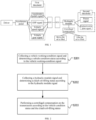
- FIG. 2 shows a step flow chart of a method of centrifugal compensation control for a transmission according to an embodiment of the present application. The method includes the following step: S201, S202, and S203.
- step S201 a vehicle working-condition signal is collected, and a vehicle condition status is determined according to the vehicle working-condition signal.
- the centrifugal compensation cut-in timing of the existing controls is only determined based on the engine speed and the actual pressure of the clutch of the transmission.
- the vehicle working-condition signal is not collected, resulting in abnormal noise in the DCT under a specific working condition.
- the specific working condition may be an in-situ large-throttle starting state, a large-throttle parking state, and a driving and gear-shifting state.
- the abnormal gear noise may occur, so the operation coverage of the vehicle working condition is narrow.
- the ECU collects various working-condition signals during operation of the vehicle.
- the vehicle working-condition signals are collected through and fed back by the ESP hydraulic control unit and speed sensor to the TCU to expand the operation coverage of working conditions, and the collected vehicle working-condition signals are compared with working conditions corresponding to different preset thresholds to determine a vehicle status corresponding to the current vehicle working-condition signal.
- a hydraulic module signal is collected, and a clutch oil-filling status is determined according to the hydraulic module signal.
- the working signal of the hydraulic module of the DCT is not collected, and oil-filling characteristics of the DCT are not fully utilized, resulting in a reduced service life of the gear of the transmission due to the impact of the gear during shifting.
- the oil-filling characteristics refer to an engagement or a disengagement of the clutch controlled by a wet dual-clutch transmission, which is achieved by filling and releasing hydraulic oil into a hydraulic oil chamber of the clutch.
- the clutch is engaged when the oil pressure chamber is filled with oil, and the clutch is disengaged when the hydraulic oil in the oil pressure chamber is discharged.
- the speed of clutch oil-filling has an important impact on a realization of a shift control rule of the DCT, a starting performance of the vehicle, a shift smoothness and other shift quality.
- the TCU is configured to collect the hydraulic module signal.
- the TCU is configured to collect the hydraulic module signal.
- the hydraulic module signal includes the position signals of the piston and the hydraulic valve plate.
- the clutch oil-filling status is determined by comparing the hydraulic module signal with preset conditions of the hydraulic module signal corresponding to different oil-filling statuses of the clutch.
- step S203 a centrifugal compensation is performed on the transmission according to the vehicle condition status and the clutch oil-filling status.
- the TCU combines the vehicle condition status fed back by the ECU with the determined clutch oil-filling status to perform the centrifugal compensation on the DCT to reduce the abnormal gear impact noise generated by the DCT during the vehicle's starting and shifting process.
- the cut-in timing of the centrifugal compensation for the DCT can be controlled through the vehicle conditions and the operations of the hydraulic module of the transmission, to reduce the abnormal gear impact noise generated by the DCT during the vehicle's starting and shifting process, and improve the product reliability.
- the vehicle working-condition signal includes an accelerator pedal signal, an ESP signal, a gear position signal and a vehicle speed signal
- the vehicle condition status includes an in-situ large-throttle starting state, a large-throttle parking state, and a driving and gear-shifting state.
- the vehicle working-condition signal is collected through a signal input device such as an ESP hydraulic control unit and a rotation speed sensor, as a condition for determining the vehicle condition status, and the current vehicle condition status of the vehicle is determined based on the vehicle working-condition signal.
- a signal input device such as an ESP hydraulic control unit and a rotation speed sensor
- the gear signal is at a first gear
- the ESP signal is a brake-free or parking signal
- the vehicle speed signal has a first speed threshold
- the vehicle condition status is the in-situ large-throttle starting state.
- the gear signal is at the first gear
- the ESP signal is a braking or parking signal
- the vehicle speed signal has a second speed threshold
- the vehicle condition status is the large-throttle parking state.
- the gear signal is at or above a second gear
- the ESP signal is the brake-free or parking signal
- the vehicle speed signal has a third speed threshold
- the vehicle condition status is the driving and gear-shifting state.
- Table 1 Corresponding conditions between vehicle working-condition signals and vehicle condition statuses Vehicle Condition Status Opening-degree of Accelerator Pedal Gear Signal ESP Signal Vehicle Speed Signal Vehicle Condition A Opening-degree above 50% 1 st gear Brake-free/parking signal 15 km/h Starting in-situ at a large throttle B Opening-degree above 50% 1 st gear Braking/parking signal 0 Parking at a large throttle C opening-degree above 30% 2nd gear or above Brake-free/parking signal Above 35 km/h Driving status
- the corresponding conditions between the vehicle working-condition signals and the vehicle condition statuses are shown in Table 1, in case that the opening-degree from the accelerator pedal signal is greater than 50%, the gear signal is at the first gear, and the ESP signal is the brake-free or parking signal and the vehicle speed signal is 15 kilometers per hour, that is, the working conditions corresponding to vehicle condition status A are met in this case, that is, the vehicle is in the in-situ large-throttle starting state in this case.
- the gear signal is at the first gear
- the ESP signal is a braking or parking signal
- the vehicle speed signal is zero, that is, the working conditions corresponding to vehicle condition status B are met in this case, that is, the vehicle is in the large-throttle parking state in this case.
- the accelerator pedal signal is greater than 30%
- the gear signal is at or above the second gear
- the ESP signal is the brake-free or parking signal
- the vehicle speed signal is 35 kilometers per hour, that is, the working conditions corresponding to vehicle condition status C are met in this case, that is, the vehicle is in the driving and gear-shifting state in this case.
- the hydraulic module signal includes a position signal of a piston and a position signal of a hydraulic valve plate;
- the clutch oil-filling status includes a status before a clutch is oil-filled and a status after the clutch is oil-filled.
- a hydraulic module signal is collected, and the step of determining the clutch oil-filling status according to the hydraulic module signal includes that: It is determined that the clutch oil-filling status is the status before the clutch is oil-filled when the position signal of the hydraulic valve plate is a switched-on signal and the position signal of the piston is moving from a bottom dead center position and to a top dead center position.
- the clutch oil-filling status is the status after the clutch is oil-filled when the position signal of the hydraulic valve plate is a switched-off signal and the position signal of the piston is moving from the top dead center position toward the bottom dead center position.
- Table 2 Conditions corresponding to the clutch oil-filling status and the hydraulic module signal Position Signal of Piston Remark s Position Signal of Hydraulic Valve Plate Oil Filling Characteristic Oil-filling Status Bottom dead center to top dead center Thrust Switched on Oil-pressure chamber is filled with oil, and the clutch is engaged Before the oil is filled Top dead center to bottom dead center Suction Switched off Hydraulic oil in the oil-pressure chamber is discharged, and the clutch is disengaged after the oil is filled
- the corresponding conditions between the clutch oil-filling status and the hydraulic module signal are shown in Table 2. It is indicated that the piston is at a lower position of the cylinder when the piston position is at the bottom dead center position; and it is indicated that the piston position is at a peak position of the cylinder when the piston position is at the top dead center position.
- the position signal of the piston moves from the bottom dead center position toward the top dead center position, indicating that the oil chamber is in an oil-inlet state, then it is indicated that a thrust signal is provided at this time, and the position signal of the hydraulic valve plate is the switched-on signal, and then the oil filling characteristic is to fill the oil-pressure chamber with oil, and the clutch is engaged, that is, the logical relationship corresponding to the clutch before the oil is filled is met in this case, that is, the clutch oil-filling status at this time is the status before the clutch is oil-filled.
- the oil-filling characteristic at this time is to discharge the hydraulic oil from the oil pressure chamber and the clutch is disengaged, that is, the logical relationship corresponding to the clutch after the oil is filled is met at this time, that is, the clutch oil-filling status at this time is the status after the clutch is oil-filled.
- the method of performing the centrifugal compensation on the transmission according to the vehicle condition status and the clutch oil-filling status may include the following steps S301-S303.
- the cut-in timing for the centrifugal compensation is determined according to the clutch oil-filling status. That is, by adding a variety of vehicle working condition information and comparing the information with the preset threshold, the current vehicle condition status is determined, and then combined with the comparison result of the clutch oil-filling status and the preset hydraulic module signal to determine the cut-in timing of the centrifugal compensation, which greatly improves the effect of centrifugal compensation.
- Table 3 Execution results corresponding to a combination of vehicle condition status and clutch oil-filling status Logical Combination Vehicle Condition Status Clutch Oil-filling Status Execution Result 1 A Before the oil is filled When the vehicle is starting in situ with a large throttle, the centrifugal compensation is performed before the clutch oil chamber is filled with oil. 2 B After the oil is filled When the vehicle is parking with a large throttle, the centrifugal compensation is performed in a state after the clutch is oil-filled. 3 C After the oil is filled When the vehicle is driving and shifting, the centrifugal compensation is performed in a state after the clutch is oil-filled.
- step S301 the centrifugal compensation is performed before the clutch is filled with oil when the vehicle condition status is the in-situ large-throttle starting state.
- the execution result corresponding to the combination of the vehicle condition status and the clutch filling state shown in Table 3 is corresponded to the logic combination 1, that is, when the vehicle condition status is the in-situ large-throttle starting state, that is, the vehicle condition status is corresponded to the logic relationship A.
- the clutch oil-filling status is before the oil-filling of the clutch, that is, the vehicle is in the in-situ large-throttle starting state
- the centrifugal compensation is performed before the clutch oil chamber is filled with oil.
- step S302 the centrifugal compensation is performed in a state after the clutch is oil-filled when the vehicle condition status is the large-throttle parking state.
- the execution result corresponding to the combination of the vehicle condition status and the clutch oil-filling status shown in Table 3 is corresponded to the logic combination 2, that is, when the vehicle condition status is the in-situ large-throttle starting state, that is, the vehicle condition status is corresponded to the logic relationship B, when the clutch oil-filling status is before the oil-filling of the clutch , that is, when the vehicle is in the large-throttle parking state, the centrifugal compensation is performed in the status after the clutch is oil-filled.
- step S303 the centrifugal compensation is performed in a state after the clutch is oil-filled when the vehicle condition status is the driving and gear-shifting state.
- the execution result corresponding to the combination of the vehicle condition status and the clutch oil-filling status shown in Table 3 is corresponded to the logic combination 2, that is, when the vehicle condition status is the in-situ large-throttle starting state, that is, the vehicle condition status is corresponded to the logic relationship C, when the clutch oil-filling status is before the oil-filling of the clutch, that is, the vehicle is in the driving and gear-shifting state, the centrifugal compensation is performed in the status after the clutch is oil-filled.
- FIG. 4 is a schematic diagram of an apparatus of centrifugal compensation control for a transmission in an embodiment of the present application.
- the apparatus include: a first acquisition module 401, a second acquisition module 402 and an execution module 403.
- the first acquisition module 401 is configured to collect a vehicle working-condition signal and determine a vehicle condition status according to the vehicle working-condition signal.
- the second acquisition module 402 is configured to collect a hydraulic module signal and determine a clutch oil-filling status according to the hydraulic module signal;
- the execution module 403 is configured to perform a centrifugal compensation on the transmission according to the vehicle condition status and the clutch oil-filling status.
- an embodiment of the present application provides a readable storage medium, in which a program of centrifugal compensation control for the transmission is stored.
- the program of centrifugal compensation control for the transmission when executed by a processor, causes steps of the method for the centrifugal compensation control of the transmission provided in a first aspect of the embodiments of the present application to be implemented.
- an embodiment of the present application provides a vehicle, including the apparatus or system of centrifugal compensation control for the transmission as provided in a third aspect of the embodiments of the present application.
- the vehicle may perform a logical calculation to determine the vehicle working condition by collecting the accelerator pedal signal, the ESP signal, the vehicle gear signal, and the vehicle speed signal.
- the vehicle working-condition signal is input into the TCU as a condition for determining the vehicle condition status.
- the TCU collects the position signal of the piston and the position signal of the hydraulic valve plate of the hydraulic module of DCT to determine whether the hydraulic module is before or after the clutch is oil-filled as a condition for determining a cut-in timing, and the centrifugal compensation is performed on the DCT through a logical matching.
- the embodiment of the present application may be provided as methods, devices, or computer program products.
- the embodiment of the present application may take the form of a full hardware embodiment, a full software embodiment, or an embodiment that combines software and hardware aspects.
- the embodiment of the present application may take the form of a computer program product implemented on one or more computer-available storage media (including but not limited to a disk storage, a CD-ROM, an optical storage, etc.) having computer-available program code embodied therein.
- Embodiments of the present application are described with reference to flow charts and/or block diagrams of methods, terminal devices (systems), and computer program products according to the embodiments of the present application.
- each process and/or block in the flow charts and/or block diagrams, and combinations of processes and/or blocks in the flow charts and/or block diagrams may be implemented by computer program instructions.
- These computer program instructions may be provided to a processor of a general-purpose computer, a special-purpose computer, an embedded processor, or other programmable data processing terminal devices to produce a machine such that the instructions, when executed by the processor of the computer or other programmable data processing terminal device, enable the functions specified in the process or processes of the flow charts and/or the block or blocks of the block diagrams to be implemented.
- These computer program instructions may also be stored in a computer-readable memory that causes a computer or other programmable data processing terminal equipment to operate in a particular manner, such that the instructions stored in the computer-readable memory produce an article of manufacture including the instruction means, the instruction means implements the functions specified in a process or processes of the flow charts and/or a block or blocks of the block diagrams.
- These computer program instructions may also be loaded onto a computer or other programmable data processing terminal equipment, so that a series of operating steps are performed on the computer or other programmable terminal equipment to produce computer-implemented processing, thereby causing the computer or other programmable terminal equipment to perform a computer-implemented process.
- the instructions executed on provide steps for implementing the functions specified in a process or processes of the flow charts and/or a block or blocks of the block diagrams.
- the device embodiments described above are only illustrative.
- the units described as separate components may or may not be physically separated.
- the components shown as units may or may not be physical units, that is, they may be located in one location, or may be distributed across multiple network units. Some or all of the modules may be selected according to actual needs to achieve the purpose of the solution of this embodiment, that, for persons of ordinary skill in the art can be understood and implemented without any creative effort.
- Various component embodiments of the present application may be implemented in hardware, or in software modules running on one or more processors, or in a combination thereof. It should be understood for persons skilled in the art that a microprocessor or a digital signal processor (DSP) may be used in practice to implement some or all functions of some or all components in the computing processing device according to the embodiments of the present application.
- DSP digital signal processor
- the present application may also be implemented as an apparatus or device program (e.g., the computer program and computer program product) for performing part or all of the methods described herein.
- Such a program for implementing the present application may be stored on a computer-readable medium, or may be in the form of one or more signals. Such signals may be downloaded from an Internet website, or provided on a carrier signal, or in any other form.
- FIG. 5 shows a computing processing device that may implement the methods according to the present application.
- the computing processing device conventionally includes a processor 1010 and a computer program product or computer-readable medium in the form of memory 1020.
- the memory 1020 may be electronic memory such as a flash memory, an EEPROM (Electrically Erasable Programmable Read Only Memory), an EPROM, a hard disk, or a ROM.
- the memory 1020 has a storage space 1030 for program codes 1031 for executing any method steps in the above-mentioned methods.
- the storage space 1030 for program codes may include individual program codes 1031 respectively used to implement various steps in the above method. These program codes may be read from or written into one or more computer program products.
- These computer program products include program code carriers such as a hard disk, a compact disk (CD), a memory card or a floppy disk. Such computer program products are typically portable or fixed storage units as described with reference to FIG. 6 .
- the storage unit may have storage segments, storage spaces, etc. arranged similarly to the memory 1020 in the computing processing device of FIG. 5 .
- the program code may, for example, be compressed in a suitable form.
- the storage unit includes a computer-readable code 103 1', i.e., a code that can be read by, for example, a processor such as 1010, which code, when executed by a computing processing device, causes the computing processing device to perform various steps of the methods described above.
Landscapes
- Engineering & Computer Science (AREA)
- General Engineering & Computer Science (AREA)
- Mechanical Engineering (AREA)
- Control Of Transmission Device (AREA)
Abstract
Description
- This application claims the benefit of
Chinese Patent Application No. 202110682731.9 filed on June 18, 2021 - The present application relates to the field of vehicle control technology, and in particular to a method, an apparatus and a system of centrifugal compensation control for a transmission, a storage medium, and a vehicle.
- The dual-clutch transmission is referred to as DCT. To improve the vehicle's starting performance, shift smoothness and shift response, a centrifugal compensation strategy is adopted in the DCT to optimize a shift operation of the DCT.
- In existing technologies, the principal centrifugal compensation control strategy for the DCT is to centrifugally supplement a torque transmission pressure of the clutch by means of an engine speed and an actual pressure of the clutch. However, under certain working conditions, an abnormal noise may be generated by the DCT, which will affect the customer's experience.
- Embodiments of the present application provide a method of centrifugal compensation control for a transmission, an apparatus, a system, a storage medium, and a vehicle, which aim to address the problems existing in the above special circumstances.
- To solve the above technical problems, the present application is implemented as follows: In accordance with a first aspect of the embodiments of the present application, a method of centrifugal compensation control for a transmission is provided. The method includes that: collecting a vehicle working-condition signal and determining a vehicle condition status according to the vehicle working-condition signal; collecting a hydraulic module signal and determining a clutch oil-filling status according to the hydraulic module signal; and performing a centrifugal compensation on the transmission according to the vehicle condition status and the clutch oil-filling status.
- Optionally, the vehicle working-condition signal includes an accelerator pedal signal, an ESP (Electronic Stability Program) signal, a gear signal and a vehicle speed signal.
- The vehicle condition status includes an in-situ large-throttle starting state, a large-throttle parking state, and a driving and gear-shifting state.
- Optionally, the step of determining the vehicle condition status according to the vehicle working-condition signal includes that:
Determining that the vehicle condition status is the in-situ large-throttle starting state in case that an opening-degree from the accelerator pedal signal is greater than a first opening-degree threshold, the gear signal is at a first gear, the ESP signal is a break-free or parking signal, and the vehicle speed signal has a first speed threshold. - Determining that the vehicle condition status is the large-throttle parking state in case that the opening-degree from the accelerator pedal signal is greater than the first opening-degree threshold, the gear signal is at the first gear, the ESP signal is a braking or parking signal, and the vehicle speed signal has a second speed threshold.
- Determining that the vehicle condition status is the driving and gear-shifting state in case that the opening-degree from the accelerator pedal signal is greater than a second opening-degree threshold, the gear signal is at or above a second gear, the ESP signal is the brake-free or parking signal, and the vehicle speed signal has a third speed threshold.
- Optionally, the hydraulic module signal includes a position signal of a piston and a position signal of a hydraulic valve plate.
- The clutch oil-filling status includes a status before a clutch is oil-filled and a status after the clutch is oil-filled.
- Optionally, the step of determining the clutch oil-filling status according to the hydraulic module signal includes that:
It is determined that the clutch oil-filling status is the status before the clutch is oil-filled in case that the position signal of the piston moves from a bottom dead center position toward a top dead center position and the position signal of the hydraulic valve plate is a switched-on signal. - It is determined that the clutch oil-filling status is the status after the clutch is oil-filled in case that the position signal of the piston moves from the top dead center position toward the bottom dead center position, and the position signal of the hydraulic valve plate is a switched-off signal.
- Optionally, the step of performing the centrifugal compensation on the transmission according to the vehicle condition status and clutch oil-filling status includes steps of: determining, according to the vehicle condition status, whether the centrifugal compensation is performed with respect to a current working condition; and determining, according to the clutch oil-filling status, a cut-in timing for the centrifugal compensation. Where, when the vehicle condition status is the in-situ large-throttle starting state, the centrifugal compensation is performed in a state before the clutch is oil-filled.
- When the vehicle condition status is the large-throttle parking state, the centrifugal compensation is performed in a state after the clutch is oil-filled.
- When the vehicle condition status is the driving and gear-shifting state, the centrifugal compensation is performed in a state after the clutch is oil-filled.
- In accordance with a second aspect of the embodiments of the present application, an apparatus of centrifugal compensation control for a transmission is provided, which includes: a first acquisition module, a second acquisition module, and an execution module.
- The first acquisition module is configured to collect a vehicle working-condition signal and determine a vehicle condition status according to the vehicle working-condition signal. The second acquisition module is configured to collect a hydraulic module signal and determine a clutch oil-filling status according to the hydraulic module signal.
- An execution module is configured to perform a centrifugal compensation on the transmission according to the vehicle condition status and clutch oil-filling status.
- In accordance with a third aspect of the embodiments of the present application, a system of centrifugal compensation control for a transmission is provided. The system includes: an ECU (Electronic Control Unit) control unit, a TCU (Transmission Control Unit) control unit, a DCT (Dual-Clutch Transmission) clutch assembly, and an accelerator pedal.
- The ECU is configured to collect a vehicle working-condition signal and determine the vehicle condition status according to the vehicle working-condition signal. The vehicle working-condition signal includes an accelerator pedal signal, an ESP signal, a gear signal, and a vehicle speed signal.
- The TCU is configured to collect a hydraulic module signal and determine a clutch oil-filling status according to the hydraulic module signal, to perform a centrifugal compensation for the DCT. The TCU is configured to collect the hydraulic module signal. The hydraulic module signal includes a position signal of a piston and a position signal of a hydraulic valve plate.
- The DCT clutch assembly is configured to execute a centrifugal compensation execution instruction issued by the TCU.
- The accelerator pedal is configured to collect control information from a vehicle owner.
- In accordance with a fourth aspect of the embodiments of the present application, a readable storage medium is provided. The storage medium stores a program of centrifugal compensation control for a transmission. The program of centrifugal compensation control for the transmission, when executed by a processor, causes steps of the method of centrifugal compensation control for the transmission proposed in the first aspect of the embodiments of the present application to be implemented.
- In accordance with a fifth aspect of the embodiments of the present application, a vehicle is provided, including the system of centrifugal compensation control for the transmission provided in the third aspect of the embodiments of the present application.
- Compared with the existing technologies, the method of centrifugal compensation control for the transmission described in this application has the following advantages that: in the present application, the vehicle working-condition signal is collected and the vehicle condition status is determined according to the vehicle working-condition signal, the hydraulic module signal is collected and the clutch oil-filling status is determined according to the hydraulic module signal, and then, the centrifugal compensation is performed on the transmission according to the vehicle condition status and the clutch oil-filling status. By adding the recognition of the accelerator pedal signal, the ESP signal, the vehicle speed signal, and the vehicle gear signal, as a condition for determining the vehicle condition status of the centrifugal compensation control strategy, and by taking a recognition of position signals of the piston and hydraulic valve plate of the hydraulic module as a condition for determining a centrifugal compensation cut-in timing of the centrifugal compensation control strategy, an operation coverage of vehicle working conditions of the centrifugal compensation control strategy is expanded, the abnormal noise of the DCT during starting or shifting is reduced, the impact of the gear during shifting is reduced, and the service life of the transmission prolonged. Moreover, the technical solution of this application is more simplified, has a low failure rate, does not require additional auxiliary hardware, and is low in cost, which has a wide range of applications, adapts to new and old models, and is conducive to upgrading old models. It can save a wire assembly as no additional system component is required. It is more convenient for after-sales troubleshooting and maintenance. The later rectification cycle is shortened, and the early identification and optimization space can provide guarantee for later rectification.
- To explain the technical solutions of the embodiments of the present application more clearly, the drawings that need to be used in the description of the embodiments of the present application will be briefly introduced below. Obviously, the drawings in the following description are merely some embodiments of the present application. For persons of ordinary skills in the art, other drawings may also be obtained based on these drawings without exerting creative efforts.
-
FIG. 1 is a schematic diagram of a system of centrifugal compensation control for a transmission in accordance with an embodiment of the present application; -
FIG. 2 is a step flow chart of a method of centrifugal compensation control for a transmission in accordance with an embodiment of the present application; -
FIG. 3 is another step flow chart of a method of centrifugal compensation control for a transmission in accordance with an embodiment of the present application; -
FIG. 4 is a schematic diagram of an apparatus of centrifugal compensation control for a transmission in accordance with an embodiment of the present application; -
FIG. 5 is a structural block diagram of an electronic device provided by an embodiment of the present application; and -
FIG. 6 is a schematic diagram of a hardware structure of the electronic equipment provided by an embodiment of the present application. - The technical solutions in the embodiments of the present application will be clearly and completely described below with reference to the drawings in the embodiments of the present application. Obviously, the described embodiments are part of the embodiments of the present application, rather than all of the embodiments. Based on the embodiments in this application, all other embodiments obtained by those of ordinary skill in the art without exerting creative efforts shall fall within the protection scope of the present application.
- In related technologies, the centrifugal compensation control strategy of the DCT is to centrifugally supplement the torque transmission pressure of the clutch by utilizing the engine speed and the actual pressure of the clutch. However, under certain working conditions, the DCT will produce abnormal noise and affect the customer's experience.
- To overcome the above problems, the present application provides a method of centrifugal compensation control for a transmission, which aims to collect a vehicle working-condition signal, determine a vehicle condition status according to the vehicle working-condition signal; collect a hydraulic module signal, and determine a clutch the oil-filling status according to the hydraulic module signal; and perform a centrifugal compensation on the transmission according to the vehicle condition status and the clutch oil-filling status. By adding a recognition of an accelerator pedal signal, an ESP signal, a vehicle speed signal, and a vehicle gear signal, as a condition of determining the vehicle condition status of the centrifugal compensation control strategy, and by taking a recognition of position signals of a piston and a hydraulic valve plate of a hydraulic module as a condition of determining a centrifugal compensation cut-in timing of the centrifugal compensation control strategy, the operation coverage of vehicle working conditions of the centrifugal compensation control strategy is expanded, an abnormal noise during starting or shifting of the DCT is reduced, the impact of the gear during shifting is reduced, and the service life of the transmission is prolonged.
- An embodiment of the present application provides a system of centrifugal compensation control for the DCT. Referring to
FIG. 1 , a schematic diagram of a system of centrifugal compensation control for a transmission is shown. As shown inFIG. 1 , the system includes: an ECU, a TCU, an accelerator pedal, and a DCT clutch assembly. - The ECU is configured to collect a vehicle working-condition signal and determine a vehicle condition status according to the vehicle working-condition signal. The vehicle working-condition signal includes an accelerator pedal signal, an ESP signals, a gear signal, and a vehicle speed signal.
- In this implementation, the ECU collects the vehicle working-condition signal while the vehicle is driving. The vehicle working-condition signal collected by the ECU includes the accelerator pedal signal, the ESP signal, the gear signal, and the vehicle speed signal. The vehicle working-condition signal is collected through and fed back by an ESP hydraulic control unit and a speed sensor to the ECU. The collected vehicle working-condition signal is used as an input and compared with a preset threshold to determine a working condition of the vehicle, and the working condition of the vehicle as an output result is fed back to the TCU.
- The TCU is configured to collect a hydraulic module signal and determine the clutch oil-filling status according to the hydraulic module signal, to perform a centrifugal compensation on the DCT. The TCU is configured to collect a hydraulic module signal. The hydraulic module signal includes a position signal of a piston and a position signal of a hydraulic valve plate.
- In this implementation, the TCU is configured to collect the hydraulic module signal. The hydraulic module signal includes the position signals of the piston and the hydraulic valve plate. The position signals of the piston and the hydraulic valve plate are collected through and fed back by a sensor of the hydraulic-module to the TCU. The TCU determines the clutch oil-filling status by comparing the collected position signals with a preset working condition, and then controls the centrifugal compensation cut-in timing of the DCT with reference to the vehicle condition.
- The accelerator pedal is configured to collect control information from a vehicle owner.
- In this implementation, the accelerator pedal belongs to a control apparatus, and a displacement transducer is installed on the accelerator pedal. When a driver steps on the accelerator pedal, the ECU electronic control unit will collect an opening variation and an acceleration of the displacement transducer, and determine the driver's driving intention according to a built-in algorithm, and then send a corresponding control signal to a control motor of an engine throttle, so as to control the engine's power output.
- The DCT clutch assembly belongs to an execution apparatus, and the DCT clutch assembly is configured to execute a centrifugal compensation execution instruction issued by the TCU.
- In this implementation, the execution apparatus, i.e., the DCT clutch assembly, executes the centrifugal compensation execution instruction issued by the TCU to perform the centrifugal compensation in a state after the clutch is oil-filled, which reduces the impact of the gear during a driving and gear-shifting state and improves the shift smoothness. Based on the same inventive concept, an embodiment of the present application provides a method of centrifugal compensation control for a transmission. Referring to
FIG. 2. FIG. 2 shows a step flow chart of a method of centrifugal compensation control for a transmission according to an embodiment of the present application. The method includes the following step: S201, S202, and S203. - In step S201, a vehicle working-condition signal is collected, and a vehicle condition status is determined according to the vehicle working-condition signal.
- In this implementation, the centrifugal compensation cut-in timing of the existing controls is only determined based on the engine speed and the actual pressure of the clutch of the transmission. The vehicle working-condition signal is not collected, resulting in abnormal noise in the DCT under a specific working condition. The specific working condition may be an in-situ large-throttle starting state, a large-throttle parking state, and a driving and gear-shifting state. When the vehicle is in the above-mentioned specific working condition, the abnormal gear noise may occur, so the operation coverage of the vehicle working condition is narrow. The ECU collects various working-condition signals during operation of the vehicle. The vehicle working-condition signals are collected through and fed back by the ESP hydraulic control unit and speed sensor to the TCU to expand the operation coverage of working conditions, and the collected vehicle working-condition signals are compared with working conditions corresponding to different preset thresholds to determine a vehicle status corresponding to the current vehicle working-condition signal. In step S202, a hydraulic module signal is collected, and a clutch oil-filling status is determined according to the hydraulic module signal.
- In this implementation, in the related arts, the working signal of the hydraulic module of the DCT is not collected, and oil-filling characteristics of the DCT are not fully utilized, resulting in a reduced service life of the gear of the transmission due to the impact of the gear during shifting. The oil-filling characteristics refer to an engagement or a disengagement of the clutch controlled by a wet dual-clutch transmission, which is achieved by filling and releasing hydraulic oil into a hydraulic oil chamber of the clutch. The clutch is engaged when the oil pressure chamber is filled with oil, and the clutch is disengaged when the hydraulic oil in the oil pressure chamber is discharged. The speed of clutch oil-filling has an important impact on a realization of a shift control rule of the DCT, a starting performance of the vehicle, a shift smoothness and other shift quality. The TCU is configured to collect the hydraulic module signal. The TCU is configured to collect the hydraulic module signal. The hydraulic module signal includes the position signals of the piston and the hydraulic valve plate. The clutch oil-filling status is determined by comparing the hydraulic module signal with preset conditions of the hydraulic module signal corresponding to different oil-filling statuses of the clutch.
- In step S203, a centrifugal compensation is performed on the transmission according to the vehicle condition status and the clutch oil-filling status.
- In this implementation, the TCU combines the vehicle condition status fed back by the ECU with the determined clutch oil-filling status to perform the centrifugal compensation on the DCT to reduce the abnormal gear impact noise generated by the DCT during the vehicle's starting and shifting process.
- In the embodiment of the present application, by adding monitoring of multiple vehicle working-condition signals and hydraulic module signals to the DCT centrifugal supplement control strategy, the cut-in timing of the centrifugal compensation for the DCT can be controlled through the vehicle conditions and the operations of the hydraulic module of the transmission, to reduce the abnormal gear impact noise generated by the DCT during the vehicle's starting and shifting process, and improve the product reliability. In one possible implementation, the vehicle working-condition signal includes an accelerator pedal signal, an ESP signal, a gear position signal and a vehicle speed signal, and the vehicle condition status includes an in-situ large-throttle starting state, a large-throttle parking state, and a driving and gear-shifting state.
- In this implementation, the vehicle working-condition signal is collected through a signal input device such as an ESP hydraulic control unit and a rotation speed sensor, as a condition for determining the vehicle condition status, and the current vehicle condition status of the vehicle is determined based on the vehicle working-condition signal.
- When an opening-degree from the accelerator pedal signal is greater than a first opening-degree threshold, the gear signal is at a first gear, the ESP signal is a brake-free or parking signal, and the vehicle speed signal has a first speed threshold, the vehicle condition status is the in-situ large-throttle starting state.
- When the opening-degree from the accelerator pedal signal is greater than the first opening-degree threshold, the gear signal is at the first gear, the ESP signal is a braking or parking signal, and the vehicle speed signal has a second speed threshold, the vehicle condition status is the large-throttle parking state.
- When the opening-degree from the accelerator pedal signal is greater than a second opening-degree threshold, the gear signal is at or above a second gear, the ESP signal is the brake-free or parking signal, and the vehicle speed signal has a third speed threshold, the vehicle condition status is the driving and gear-shifting state.
Table 1: Corresponding conditions between vehicle working-condition signals and vehicle condition statuses Vehicle Condition Status Opening-degree of Accelerator Pedal Gear Signal ESP Signal Vehicle Speed Signal Vehicle Condition A Opening-degree above 50% 1 st gear Brake-free/parking signal 15 km/h Starting in-situ at a large throttle B Opening-degree above 50% 1 st gear Braking/parking signal 0 Parking at a large throttle C opening-degree above 30% 2nd gear or above Brake-free/parking signal Above 35 km/h Driving status - In this implementation, the corresponding conditions between the vehicle working-condition signals and the vehicle condition statuses are shown in Table 1, in case that the opening-degree from the accelerator pedal signal is greater than 50%, the gear signal is at the first gear, and the ESP signal is the brake-free or parking signal and the vehicle speed signal is 15 kilometers per hour, that is, the working conditions corresponding to vehicle condition status A are met in this case, that is, the vehicle is in the in-situ large-throttle starting state in this case.
- In case that the opening-degree from the accelerator pedal signal is greater than 50%, the gear signal is at the first gear, the ESP signal is a braking or parking signal and the vehicle speed signal is zero, that is, the working conditions corresponding to vehicle condition status B are met in this case, that is, the vehicle is in the large-throttle parking state in this case.
- In case that the accelerator pedal signal is greater than 30%, the gear signal is at or above the second gear, the ESP signal is the brake-free or parking signal and the vehicle speed signal is 35 kilometers per hour, that is, the working conditions corresponding to vehicle condition status C are met in this case, that is, the vehicle is in the driving and gear-shifting state in this case.
- In a possible implementation, the hydraulic module signal includes a position signal of a piston and a position signal of a hydraulic valve plate; the clutch oil-filling status includes a status before a clutch is oil-filled and a status after the clutch is oil-filled.
- In this implementation, it is determined, by adding signal collections of the position signals of the piston and hydraulic valve plate of the hydraulic module, whether the hydraulic module has completed the oil filling of a hydraulic chamber of the clutch, as a condition for determining the cut-in timing of the centrifugal compensation control, where the oil-filling characteristic of the DCT is fully utilized.
- In another possible implementation, a hydraulic module signal is collected, and the step of determining the clutch oil-filling status according to the hydraulic module signal includes that:
It is determined that the clutch oil-filling status is the status before the clutch is oil-filled when the position signal of the hydraulic valve plate is a switched-on signal and the position signal of the piston is moving from a bottom dead center position and to a top dead center position. - It is determined that the clutch oil-filling status is the status after the clutch is oil-filled when the position signal of the hydraulic valve plate is a switched-off signal and the position signal of the piston is moving from the top dead center position toward the bottom dead center position.
Table 2: Conditions corresponding to the clutch oil-filling status and the hydraulic module signal Position Signal of Piston Remark s Position Signal of Hydraulic Valve Plate Oil Filling Characteristic Oil-filling Status Bottom dead center to top dead center Thrust Switched on Oil-pressure chamber is filled with oil, and the clutch is engaged Before the oil is filled Top dead center to bottom dead center Suction Switched off Hydraulic oil in the oil-pressure chamber is discharged, and the clutch is disengaged after the oil is filled - In this implementation, the corresponding conditions between the clutch oil-filling status and the hydraulic module signal are shown in Table 2. It is indicated that the piston is at a lower position of the cylinder when the piston position is at the bottom dead center position; and it is indicated that the piston position is at a peak position of the cylinder when the piston position is at the top dead center position. When the position signal of the piston moves from the bottom dead center position toward the top dead center position, indicating that the oil chamber is in an oil-inlet state, then it is indicated that a thrust signal is provided at this time, and the position signal of the hydraulic valve plate is the switched-on signal, and then the oil filling characteristic is to fill the oil-pressure chamber with oil, and the clutch is engaged, that is, the logical relationship corresponding to the clutch before the oil is filled is met in this case, that is, the clutch oil-filling status at this time is the status before the clutch is oil-filled.
- When the position signal of the piston moves from the top dead center position toward the bottom dead center position, indicating that the oil chamber is in an oil-outlet state, then it is indicated that a suction signal is provided at this time, and the position signal of the hydraulic valve plate is the switched-off signal. The oil-filling characteristic at this time is to discharge the hydraulic oil from the oil pressure chamber and the clutch is disengaged, that is, the logical relationship corresponding to the clutch after the oil is filled is met at this time, that is, the clutch oil-filling status at this time is the status after the clutch is oil-filled.
- As shown in
FIG. 3 , the method of performing the centrifugal compensation on the transmission according to the vehicle condition status and the clutch oil-filling status may include the following steps S301-S303. - In this implementation, it is determined according to the vehicle condition status whether a centrifugal compensation is performed with respect to the current working condition, that is, the cut-in timing for the centrifugal compensation is determined according to the clutch oil-filling status. That is, by adding a variety of vehicle working condition information and comparing the information with the preset threshold, the current vehicle condition status is determined, and then combined with the comparison result of the clutch oil-filling status and the preset hydraulic module signal to determine the cut-in timing of the centrifugal compensation, which greatly improves the effect of centrifugal compensation.
Table 3: Execution results corresponding to a combination of vehicle condition status and clutch oil-filling status Logical Combination Vehicle Condition Status Clutch Oil-filling Status Execution Result 1 A Before the oil is filled When the vehicle is starting in situ with a large throttle, the centrifugal compensation is performed before the clutch oil chamber is filled with oil. 2 B After the oil is filled When the vehicle is parking with a large throttle, the centrifugal compensation is performed in a state after the clutch is oil-filled. 3 C After the oil is filled When the vehicle is driving and shifting, the centrifugal compensation is performed in a state after the clutch is oil-filled. - In step S301, the centrifugal compensation is performed before the clutch is filled with oil when the vehicle condition status is the in-situ large-throttle starting state.
- In this implementation, the execution result corresponding to the combination of the vehicle condition status and the clutch filling state shown in Table 3 is corresponded to the logic combination 1, that is, when the vehicle condition status is the in-situ large-throttle starting state, that is, the vehicle condition status is corresponded to the logic relationship A. When the clutch oil-filling status is before the oil-filling of the clutch, that is, the vehicle is in the in-situ large-throttle starting state, the centrifugal compensation is performed before the clutch oil chamber is filled with oil.
- In step S302, the centrifugal compensation is performed in a state after the clutch is oil-filled when the vehicle condition status is the large-throttle parking state.
- In this implementation, the execution result corresponding to the combination of the vehicle condition status and the clutch oil-filling status shown in Table 3 is corresponded to the logic combination 2, that is, when the vehicle condition status is the in-situ large-throttle starting state, that is, the vehicle condition status is corresponded to the logic relationship B, when the clutch oil-filling status is before the oil-filling of the clutch , that is, when the vehicle is in the large-throttle parking state, the centrifugal compensation is performed in the status after the clutch is oil-filled.
- In step S303, the centrifugal compensation is performed in a state after the clutch is oil-filled when the vehicle condition status is the driving and gear-shifting state.
- In this implementation, the execution result corresponding to the combination of the vehicle condition status and the clutch oil-filling status shown in Table 3 is corresponded to the logic combination 2, that is, when the vehicle condition status is the in-situ large-throttle starting state, that is, the vehicle condition status is corresponded to the logic relationship C, when the clutch oil-filling status is before the oil-filling of the clutch, that is, the vehicle is in the driving and gear-shifting state, the centrifugal compensation is performed in the status after the clutch is oil-filled.
- Based on the same inventive concept, an apparatus of centrifugal compensation control for a transmission is provided in this application. Referring to
FIG. 4 , which is a schematic diagram of an apparatus of centrifugal compensation control for a transmission in an embodiment of the present application. As shown inFIG. 4 , the apparatus include: afirst acquisition module 401, asecond acquisition module 402 and anexecution module 403. Thefirst acquisition module 401 is configured to collect a vehicle working-condition signal and determine a vehicle condition status according to the vehicle working-condition signal. - The
second acquisition module 402 is configured to collect a hydraulic module signal and determine a clutch oil-filling status according to the hydraulic module signal; - The
execution module 403 is configured to perform a centrifugal compensation on the transmission according to the vehicle condition status and the clutch oil-filling status. Based on the same inventive concept, an embodiment of the present application provides a readable storage medium, in which a program of centrifugal compensation control for the transmission is stored. The program of centrifugal compensation control for the transmission, when executed by a processor, causes steps of the method for the centrifugal compensation control of the transmission provided in a first aspect of the embodiments of the present application to be implemented. - Based on the same inventive concept, an embodiment of the present application provides a vehicle, including the apparatus or system of centrifugal compensation control for the transmission as provided in a third aspect of the embodiments of the present application. In this implementation, the vehicle may perform a logical calculation to determine the vehicle working condition by collecting the accelerator pedal signal, the ESP signal, the vehicle gear signal, and the vehicle speed signal. The vehicle working-condition signal is input into the TCU as a condition for determining the vehicle condition status. Then, the TCU collects the position signal of the piston and the position signal of the hydraulic valve plate of the hydraulic module of DCT to determine whether the hydraulic module is before or after the clutch is oil-filled as a condition for determining a cut-in timing, and the centrifugal compensation is performed on the DCT through a logical matching.
- It should be understood for persons skilled in the art that examples of the embodiments of the present application may be provided as methods, devices, or computer program products. Thus, the embodiment of the present application may take the form of a full hardware embodiment, a full software embodiment, or an embodiment that combines software and hardware aspects. Furthermore, the embodiment of the present application may take the form of a computer program product implemented on one or more computer-available storage media (including but not limited to a disk storage, a CD-ROM, an optical storage, etc.) having computer-available program code embodied therein. Embodiments of the present application are described with reference to flow charts and/or block diagrams of methods, terminal devices (systems), and computer program products according to the embodiments of the present application. It will be understood that each process and/or block in the flow charts and/or block diagrams, and combinations of processes and/or blocks in the flow charts and/or block diagrams, may be implemented by computer program instructions. These computer program instructions may be provided to a processor of a general-purpose computer, a special-purpose computer, an embedded processor, or other programmable data processing terminal devices to produce a machine such that the instructions, when executed by the processor of the computer or other programmable data processing terminal device, enable the functions specified in the process or processes of the flow charts and/or the block or blocks of the block diagrams to be implemented.
- These computer program instructions may also be stored in a computer-readable memory that causes a computer or other programmable data processing terminal equipment to operate in a particular manner, such that the instructions stored in the computer-readable memory produce an article of manufacture including the instruction means, the instruction means implements the functions specified in a process or processes of the flow charts and/or a block or blocks of the block diagrams.
- These computer program instructions may also be loaded onto a computer or other programmable data processing terminal equipment, so that a series of operating steps are performed on the computer or other programmable terminal equipment to produce computer-implemented processing, thereby causing the computer or other programmable terminal equipment to perform a computer-implemented process. The instructions executed on provide steps for implementing the functions specified in a process or processes of the flow charts and/or a block or blocks of the block diagrams.
- The device embodiments described above are only illustrative. The units described as separate components may or may not be physically separated. The components shown as units may or may not be physical units, that is, they may be located in one location, or may be distributed across multiple network units. Some or all of the modules may be selected according to actual needs to achieve the purpose of the solution of this embodiment, that, for persons of ordinary skill in the art can be understood and implemented without any creative effort.
- Various component embodiments of the present application may be implemented in hardware, or in software modules running on one or more processors, or in a combination thereof. It should be understood for persons skilled in the art that a microprocessor or a digital signal processor (DSP) may be used in practice to implement some or all functions of some or all components in the computing processing device according to the embodiments of the present application. The present application may also be implemented as an apparatus or device program (e.g., the computer program and computer program product) for performing part or all of the methods described herein. Such a program for implementing the present application may be stored on a computer-readable medium, or may be in the form of one or more signals. Such signals may be downloaded from an Internet website, or provided on a carrier signal, or in any other form.
- For example,
FIG. 5 shows a computing processing device that may implement the methods according to the present application. The computing processing device conventionally includes aprocessor 1010 and a computer program product or computer-readable medium in the form ofmemory 1020. Thememory 1020 may be electronic memory such as a flash memory, an EEPROM (Electrically Erasable Programmable Read Only Memory), an EPROM, a hard disk, or a ROM. Thememory 1020 has astorage space 1030 forprogram codes 1031 for executing any method steps in the above-mentioned methods. For example, thestorage space 1030 for program codes may includeindividual program codes 1031 respectively used to implement various steps in the above method. These program codes may be read from or written into one or more computer program products. These computer program products include program code carriers such as a hard disk, a compact disk (CD), a memory card or a floppy disk. Such computer program products are typically portable or fixed storage units as described with reference toFIG. 6 . The storage unit may have storage segments, storage spaces, etc. arranged similarly to thememory 1020 in the computing processing device ofFIG. 5 . The program code may, for example, be compressed in a suitable form. Typically, the storage unit includes a computer-readable code 103 1', i.e., a code that can be read by, for example, a processor such as 1010, which code, when executed by a computing processing device, causes the computing processing device to perform various steps of the methods described above. - Although preferred embodiments of the embodiments of the present application have been described, those skilled in the art may make additional variations and modifications to these embodiments once the basic inventive concepts are acknowledged. Therefore, the appended claims are intended to be construed to include the preferred embodiments and all variations and modifications that fall within the scope of the embodiments of the present application.
- Finally, it should be noted that in this article, relational terms such as first and second are only used to distinguish one entity or operation from another entity or operation, and do not necessarily require or imply any such actual relationship or sequence between these entities or operations. Furthermore, the terms "comprise," "include," or any other variation thereof are intended to cover a non-exclusive inclusion such that a process, a method, an article, or a terminal equipment that includes a list of elements includes not only those elements, but also elements not expressly listed or other elements inherent to such process, method, article or terminal equipment. In the absence of further limitation, an element defined by the statement "comprises/comprising a..." does not exclude the presence of additional identical elements in a process, method, article or terminal equipment that includes the stated element.
- The above is a detailed introduction to a method of centrifugal compensation control for a transmission, a device, a system, a storage medium and a vehicle provided by the present application. Specific examples are used in this article to illustrate the principles and implementation methods of the present application. The illustration of the above embodiments is intended only to assist in understanding the methodology and the core idea of the present application. Meanwhile, for persons of ordinary skill in the field, there may be variations in the specific implementations and the range of application based on the ideas of the present application. In summary, the content of this specification should not be construed as a limitation on this application.
Claims (12)
- A method of centrifugal compensation control for a transmission, characterized in that, the method is applied to a DCT, and comprises steps of:collecting a vehicle working-condition signal, and determining a vehicle condition status according to the vehicle working-condition signal;collecting a hydraulic module signal, and determining a clutch oil-filling status according to the hydraulic module signal;performing a centrifugal compensation on the transmission according to the vehicle condition status and the clutch oil-filling status.
- The method of centrifugal compensation control for the transmission according to claim 1, characterized in that, the vehicle working-condition signal comprises an accelerator pedal signal, an ESP signal, a gear signal and a vehicle speed signal;
the vehicle condition status comprises an in-situ large-throttle starting state, a large-throttle parking state, and a driving and gear-shifting state. - The method of centrifugal compensation control for the transmission according to claim 2, characterized in that, the step of determining the vehicle condition status according to the vehicle working-condition signal comprises:determining that the vehicle condition status is the in-situ large-throttle starting state in case that an opening-degree from the accelerator pedal signal is greater than a first opening-degree threshold, the gear signal is at a first gear, the ESP signal is a break-free or parking signal, and the vehicle speed signal has a first speed threshold;determining that the vehicle condition status is the large-throttle parking state in case that the opening-degree from the accelerator pedal signal is greater than the first opening-degree threshold, the gear signal is at the first gear, the ESP signal is a braking or parking signal, and the vehicle speed signal has a second speed threshold; anddetermining that the vehicle condition status is the driving and gear-shifting state in case that the opening-degree from the accelerator pedal signal is greater than a second opening-degree threshold, the gear signal is at or above a second gear, the ESP signal is the brake-free or parking signal, and the vehicle speed signal has a third speed threshold.
- The method of centrifugal compensation control for the transmission according to claim 1, characterized in that, the hydraulic module signal comprises a position signal of a piston and a position signal of a hydraulic valve plate;
the clutch oil-filling status comprises a status before a clutch is oil-filled and a status after the clutch is oil-filled. - The method of centrifugal compensation control for the transmission according to claim 4, characterized in that, the step of determining the clutch oil-filling status according to the hydraulic module signal comprises:determining that the clutch oil-filling status is the status before the clutch is oil-filled in case that the position signal of the piston moves from a bottom dead center position toward a top dead center position and the position signal of the hydraulic valve plate is a switched-on signal; anddetermining that the clutch oil-filling status is the status after the clutch is oil-filled in case that the position signal of the piston moves from the top dead center position toward the bottom dead center position, and the position signal of the hydraulic valve plate is a switched-off signal.
- The method of centrifugal compensation control for the transmission according to claim 1, characterized in that, the step of performing the centrifugal compensation on the transmission according to the vehicle condition status and the clutch oil-filling status comprises:determining, according to the vehicle condition status, whether the centrifugal compensation is performed with respect to a current working condition;determining, according to the clutch oil-filling status, a cut-in timing for the centrifugal compensation;wherein the centrifugal compensation is performed in a state before a clutch is oiled-filled when the vehicle condition status is an in-situ large-throttle starting state;the centrifugal compensation is performed in a state after the clutch is oil-filled when the vehicle condition status is a large-throttle parking state; andthe centrifugal compensation is performed in a state after the clutch is oil-filled when the vehicle condition status is a driving and gear-shifting state.
- An apparatus of centrifugal compensation control for a transmission, characterized in that, the apparatus comprises:a first acquisition module, configured to collect a vehicle working-condition signal and determine a vehicle condition status according to the vehicle working-condition signal;a second acquisition module, configured to collect a hydraulic module signal and determine a clutch oil-filling status according to the hydraulic module signal; andan execution module, configured to perform a centrifugal compensation on the transmission according to the vehicle condition status and clutch oil-filling status.
- A system of centrifugal compensation control for a transmission, characterized in that, the system comprises:an ECU, configured to collect a vehicle working-condition signal and determine a vehicle condition status according to the vehicle working-condition signal, the vehicle working-condition signal comprises an accelerator pedal signal, an ESP signal, a gear signal, and a vehicle speed signal;a TCU, configured to collect a hydraulic module signal and determine a clutch oil-filling status according to the hydraulic module signal, to perform a centrifugal compensation on the DCT, the TCU is configured to collect the hydraulic module signal, the hydraulic module signal comprises a position signal of a piston and a position signal of a hydraulic valve plate;a DCT clutch assembly, configured to execute a centrifugal compensation execution instruction issued by the TCU; andan accelerator pedal, configured to collect control information from a vehicle owner.
- A vehicle, characterized by comprising the system of centrifugal compensation control for the transmission according to claim 8.
- An electronic device, characterized by comprising a processor, a memory and a program or instruction stored on the memory and executable on the processor, the program or instruction, when executed by the processor, enables steps of the method of centrifugal compensation control for the transmission according to any one of claims 1-6 to be implemented.
- A computer program comprising a computer readable code that, when running on a computing processing device, causes the computing processing device to perform steps of the method of centrifugal compensation control for the transmission according to any one of claims 1-6.
- A readable storage medium, characterized in that, the readable storage medium stores a program or instruction, and the program or instruction, when executed by a processor, causes the computer program according to claim 11 to be implemented.
Applications Claiming Priority (2)
| Application Number | Priority Date | Filing Date | Title |
|---|---|---|---|
| CN202110682731.9A CN114811026B (en) | 2021-06-18 | 2021-06-18 | Gearbox centrifugal compensation control method, device, system, storage medium and vehicle |
| PCT/CN2022/098388 WO2022262673A1 (en) | 2021-06-18 | 2022-06-13 | Centrifugal compensation control method, apparatus and system for transmission, and storage medium and vehicle |
Publications (3)
| Publication Number | Publication Date |
|---|---|
| EP4343177A1 true EP4343177A1 (en) | 2024-03-27 |
| EP4343177A4 EP4343177A4 (en) | 2024-10-09 |
| EP4343177B1 EP4343177B1 (en) | 2025-12-03 |
Family
ID=82525939
Family Applications (1)
| Application Number | Title | Priority Date | Filing Date |
|---|---|---|---|
| EP22824153.5A Active EP4343177B1 (en) | 2021-06-18 | 2022-06-13 | Centrifugal compensation control method, apparatus and system for transmission, and storage medium and vehicle |
Country Status (3)
| Country | Link |
|---|---|
| EP (1) | EP4343177B1 (en) |
| CN (1) | CN114811026B (en) |
| WO (1) | WO2022262673A1 (en) |
Families Citing this family (1)
| Publication number | Priority date | Publication date | Assignee | Title |
|---|---|---|---|---|
| CN117212360A (en) * | 2023-09-26 | 2023-12-12 | 重庆青山工业有限责任公司 | Multi-paradigm clutch oil filling method and system based on working conditions |
Family Cites Families (11)
| Publication number | Priority date | Publication date | Assignee | Title |
|---|---|---|---|---|
| EP1195537B1 (en) * | 2000-10-05 | 2003-03-12 | Ford Global Technologies, Inc., A subsidiary of Ford Motor Company | Transmission double clutch with two input shafts |
| CN102213310B (en) * | 2010-04-07 | 2014-09-24 | 通用汽车环球科技运作有限责任公司 | System and method for automatic transmission shift control |
| DE102013108509B4 (en) * | 2012-08-14 | 2024-02-15 | GM Global Technology Operations LLC (n. d. Gesetzen des Staates Delaware) | Transmission clutch piston compensator feed circuit |
| CN106286814B (en) * | 2016-10-28 | 2018-02-13 | 安徽江淮汽车集团股份有限公司 | A kind of oil-filled control method of wet-type dual-clutch and system |
| CN110094496B (en) * | 2018-01-31 | 2020-08-07 | 长城汽车股份有限公司 | A torque control method, device and vehicle |
| CN108343733A (en) * | 2018-02-13 | 2018-07-31 | 重庆长安汽车股份有限公司 | A kind of the clutch temp control method and system of wet type DCT |
| CN110725944B (en) * | 2018-07-17 | 2020-12-18 | 长城汽车股份有限公司 | Shift compensation control method, system and vehicle for vehicle |
| CN108953588B (en) * | 2018-07-18 | 2020-05-22 | 南京奥吉智能汽车技术研究院有限公司 | Pressure self-adaptive control method of wet-type double clutch |
| KR102177599B1 (en) * | 2018-12-12 | 2020-11-12 | 현대트랜시스(주) | Shift control method for vehecle with dct |
| KR102598966B1 (en) * | 2019-05-17 | 2023-11-06 | 현대자동차주식회사 | Transmission control apparatus and transmission control method of vehicle |
| CN112161050B (en) * | 2020-10-31 | 2021-12-31 | 重庆青山工业有限责任公司 | Clutch pressure compensation control method of wet DCT |
-
2021
- 2021-06-18 CN CN202110682731.9A patent/CN114811026B/en active Active
-
2022
- 2022-06-13 EP EP22824153.5A patent/EP4343177B1/en active Active
- 2022-06-13 WO PCT/CN2022/098388 patent/WO2022262673A1/en not_active Ceased
Also Published As
| Publication number | Publication date |
|---|---|
| EP4343177B1 (en) | 2025-12-03 |
| WO2022262673A1 (en) | 2022-12-22 |
| CN114811026B (en) | 2023-07-25 |
| CN114811026A (en) | 2022-07-29 |
| EP4343177A4 (en) | 2024-10-09 |
Similar Documents
| Publication | Publication Date | Title |
|---|---|---|
| US8554452B2 (en) | Economic ISG system and control method thereof | |
| CN109353226B (en) | A torque filter control method for pure electric vehicles | |
| EP4343177A1 (en) | Centrifugal compensation control method, apparatus and system for transmission, and storage medium and vehicle | |
| CN112208345B (en) | Vehicle energy recovery control method, storage medium, and electronic device | |
| CN102923078A (en) | Automobile air compression device and control method | |
| US10814859B2 (en) | Hybrid electric vehicle and method of controlling shift thereof | |
| CN114056301B (en) | Soft stop control method and system of electronic control brake booster and vehicle | |
| CN114738399A (en) | Pressure zero point self-adaptive control method for wet DCT (dual clutch transmission) | |
| CN118977715A (en) | Vehicle torque control method, device, and electronic equipment | |
| CN113799760A (en) | Automobile energy management method, device, equipment and computer readable storage medium | |
| CN115013118B (en) | Crankcase pressure control method and device, vehicle and electronic device | |
| CN116677477B (en) | Methods, devices, computer-readable storage media, and vehicles for controlling engine oil dilution ratio | |
| EP2767815B1 (en) | System for monitoring the wear of the gears of a vehicle transmission | |
| CN118220112A (en) | Engine torque control method and device | |
| CN113978442B (en) | Vehicle control method and unit, vehicle control system and vehicle | |
| CN116443005B (en) | Vehicle control method, device, vehicle and storage medium | |
| CN114542302A (en) | Engine control method and related device | |
| CN110525423B (en) | Control system and method for safe service of complex electromechanical system based on reliability prediction | |
| CN111976701A (en) | AMT control method, device and equipment for mining truck | |
| CN114641633B (en) | Clutch assembly for automated manual transmission | |
| CN120426277B (en) | Hydraulic system health assessment method, device and vehicle | |
| CN119773754A (en) | Method and device for predicting power output data of vehicle in multi-driving scene | |
| CN115596560B (en) | Startup control method for electronic pump used in automobile hydraulic system | |
| CN121989910A (en) | Vehicle control methods, devices, equipment, storage media and program products | |
| CN117097728A (en) | Speed reducer operation data recovery method and system |
Legal Events
| Date | Code | Title | Description |
|---|---|---|---|
| STAA | Information on the status of an ep patent application or granted ep patent |
Free format text: STATUS: THE INTERNATIONAL PUBLICATION HAS BEEN MADE |
|
| PUAI | Public reference made under article 153(3) epc to a published international application that has entered the european phase |
Free format text: ORIGINAL CODE: 0009012 |
|
| STAA | Information on the status of an ep patent application or granted ep patent |
Free format text: STATUS: REQUEST FOR EXAMINATION WAS MADE |
|
| 17P | Request for examination filed |
Effective date: 20231218 |
|
| AK | Designated contracting states |
Kind code of ref document: A1 Designated state(s): AL AT BE BG CH CY CZ DE DK EE ES FI FR GB GR HR HU IE IS IT LI LT LU LV MC MK MT NL NO PL PT RO RS SE SI SK SM TR |
|
| DAV | Request for validation of the european patent (deleted) | ||
| DAX | Request for extension of the european patent (deleted) | ||
| A4 | Supplementary search report drawn up and despatched |
Effective date: 20240911 |
|
| RIC1 | Information provided on ipc code assigned before grant |
Ipc: F16H 61/02 20060101AFI20240905BHEP |
|
| REG | Reference to a national code |
Ref country code: DE Ref legal event code: R079 Free format text: PREVIOUS MAIN CLASS: F16H0061020000 Ref country code: DE Ref legal event code: R079 Ref document number: 602022026280 Country of ref document: DE Free format text: PREVIOUS MAIN CLASS: F16H0061020000 Ipc: F16H0063500000 |
|
| GRAP | Despatch of communication of intention to grant a patent |
Free format text: ORIGINAL CODE: EPIDOSNIGR1 |
|
| RIC1 | Information provided on ipc code assigned before grant |
Ipc: F16H 63/50 20060101AFI20250616BHEP |
|
| STAA | Information on the status of an ep patent application or granted ep patent |
Free format text: STATUS: GRANT OF PATENT IS INTENDED |
|
| INTG | Intention to grant announced |
Effective date: 20250723 |
|
| GRAS | Grant fee paid |
Free format text: ORIGINAL CODE: EPIDOSNIGR3 |
|
| P01 | Opt-out of the competence of the unified patent court (upc) registered |
Free format text: CASE NUMBER: UPC_APP_7526_4343177/2025 Effective date: 20250918 |
|
| GRAA | (expected) grant |
Free format text: ORIGINAL CODE: 0009210 |
|
| STAA | Information on the status of an ep patent application or granted ep patent |
Free format text: STATUS: THE PATENT HAS BEEN GRANTED |
|
| AK | Designated contracting states |
Kind code of ref document: B1 Designated state(s): AL AT BE BG CH CY CZ DE DK EE ES FI FR GB GR HR HU IE IS IT LI LT LU LV MC MK MT NL NO PL PT RO RS SE SI SK SM TR |
|
| REG | Reference to a national code |
Ref country code: CH Ref legal event code: F10 Free format text: ST27 STATUS EVENT CODE: U-0-0-F10-F00 (AS PROVIDED BY THE NATIONAL OFFICE) Effective date: 20251203 Ref country code: GB Ref legal event code: FG4D |
|
| REG | Reference to a national code |
Ref country code: DE Ref legal event code: R096 Ref document number: 602022026280 Country of ref document: DE |
|
| REG | Reference to a national code |
Ref country code: IE Ref legal event code: FG4D |
|
| REG | Reference to a national code |
Ref country code: NL Ref legal event code: MP Effective date: 20251203 |
|
| PG25 | Lapsed in a contracting state [announced via postgrant information from national office to epo] |
Ref country code: ES Free format text: LAPSE BECAUSE OF FAILURE TO SUBMIT A TRANSLATION OF THE DESCRIPTION OR TO PAY THE FEE WITHIN THE PRESCRIBED TIME-LIMIT Effective date: 20251203 |
|
| REG | Reference to a national code |
Ref country code: LT Ref legal event code: MG9D |
|
| PG25 | Lapsed in a contracting state [announced via postgrant information from national office to epo] |
Ref country code: NO Free format text: LAPSE BECAUSE OF FAILURE TO SUBMIT A TRANSLATION OF THE DESCRIPTION OR TO PAY THE FEE WITHIN THE PRESCRIBED TIME-LIMIT Effective date: 20260303 |
|
| PG25 | Lapsed in a contracting state [announced via postgrant information from national office to epo] |
Ref country code: FI Free format text: LAPSE BECAUSE OF FAILURE TO SUBMIT A TRANSLATION OF THE DESCRIPTION OR TO PAY THE FEE WITHIN THE PRESCRIBED TIME-LIMIT Effective date: 20251203 Ref country code: HR Free format text: LAPSE BECAUSE OF FAILURE TO SUBMIT A TRANSLATION OF THE DESCRIPTION OR TO PAY THE FEE WITHIN THE PRESCRIBED TIME-LIMIT Effective date: 20251203 |
|
| PG25 | Lapsed in a contracting state [announced via postgrant information from national office to epo] |
Ref country code: RS Free format text: LAPSE BECAUSE OF FAILURE TO SUBMIT A TRANSLATION OF THE DESCRIPTION OR TO PAY THE FEE WITHIN THE PRESCRIBED TIME-LIMIT Effective date: 20260303 |
|
| PG25 | Lapsed in a contracting state [announced via postgrant information from national office to epo] |
Ref country code: PL Free format text: LAPSE BECAUSE OF FAILURE TO SUBMIT A TRANSLATION OF THE DESCRIPTION OR TO PAY THE FEE WITHIN THE PRESCRIBED TIME-LIMIT Effective date: 20251203 |
|
| PG25 | Lapsed in a contracting state [announced via postgrant information from national office to epo] |
Ref country code: LV Free format text: LAPSE BECAUSE OF FAILURE TO SUBMIT A TRANSLATION OF THE DESCRIPTION OR TO PAY THE FEE WITHIN THE PRESCRIBED TIME-LIMIT Effective date: 20251203 |