EP4343120A1 - Passively orientable pressure probe - Google Patents
Passively orientable pressure probe Download PDFInfo
- Publication number
- EP4343120A1 EP4343120A1 EP23198052.5A EP23198052A EP4343120A1 EP 4343120 A1 EP4343120 A1 EP 4343120A1 EP 23198052 A EP23198052 A EP 23198052A EP 4343120 A1 EP4343120 A1 EP 4343120A1
- Authority
- EP
- European Patent Office
- Prior art keywords
- flow
- movable member
- pressure probe
- central axis
- pressure
- Prior art date
- Legal status (The legal status is an assumption and is not a legal conclusion. Google has not performed a legal analysis and makes no representation as to the accuracy of the status listed.)
- Pending
Links
Images



Classifications
-
- F—MECHANICAL ENGINEERING; LIGHTING; HEATING; WEAPONS; BLASTING
- F01—MACHINES OR ENGINES IN GENERAL; ENGINE PLANTS IN GENERAL; STEAM ENGINES
- F01D—NON-POSITIVE DISPLACEMENT MACHINES OR ENGINES, e.g. STEAM TURBINES
- F01D17/00—Regulating or controlling by varying flow
- F01D17/02—Arrangement of sensing elements
- F01D17/08—Arrangement of sensing elements responsive to condition of working-fluid, e.g. pressure
-
- F—MECHANICAL ENGINEERING; LIGHTING; HEATING; WEAPONS; BLASTING
- F01—MACHINES OR ENGINES IN GENERAL; ENGINE PLANTS IN GENERAL; STEAM ENGINES
- F01D—NON-POSITIVE DISPLACEMENT MACHINES OR ENGINES, e.g. STEAM TURBINES
- F01D21/00—Shutting-down of machines or engines, e.g. in emergency; Regulating, controlling, or safety means not otherwise provided for
- F01D21/003—Arrangements for testing or measuring
-
- F—MECHANICAL ENGINEERING; LIGHTING; HEATING; WEAPONS; BLASTING
- F01—MACHINES OR ENGINES IN GENERAL; ENGINE PLANTS IN GENERAL; STEAM ENGINES
- F01D—NON-POSITIVE DISPLACEMENT MACHINES OR ENGINES, e.g. STEAM TURBINES
- F01D21/00—Shutting-down of machines or engines, e.g. in emergency; Regulating, controlling, or safety means not otherwise provided for
- F01D21/14—Shutting-down of machines or engines, e.g. in emergency; Regulating, controlling, or safety means not otherwise provided for responsive to other specific conditions
-
- G—PHYSICS
- G01—MEASURING; TESTING
- G01F—MEASURING VOLUME, VOLUME FLOW, MASS FLOW OR LIQUID LEVEL; METERING BY VOLUME
- G01F1/00—Measuring the volume flow or mass flow of fluid or fluent solid material wherein the fluid passes through a meter in a continuous flow
- G01F1/05—Measuring the volume flow or mass flow of fluid or fluent solid material wherein the fluid passes through a meter in a continuous flow by using mechanical effects
- G01F1/34—Measuring the volume flow or mass flow of fluid or fluent solid material wherein the fluid passes through a meter in a continuous flow by using mechanical effects by measuring pressure or differential pressure
- G01F1/36—Measuring the volume flow or mass flow of fluid or fluent solid material wherein the fluid passes through a meter in a continuous flow by using mechanical effects by measuring pressure or differential pressure the pressure or differential pressure being created by the use of flow constriction
- G01F1/40—Details of construction of the flow constriction devices
- G01F1/46—Pitot tubes
-
- F—MECHANICAL ENGINEERING; LIGHTING; HEATING; WEAPONS; BLASTING
- F05—INDEXING SCHEMES RELATING TO ENGINES OR PUMPS IN VARIOUS SUBCLASSES OF CLASSES F01-F04
- F05D—INDEXING SCHEME FOR ASPECTS RELATING TO NON-POSITIVE-DISPLACEMENT MACHINES OR ENGINES, GAS-TURBINES OR JET-PROPULSION PLANTS
- F05D2250/00—Geometry
- F05D2250/20—Three-dimensional
- F05D2250/24—Three-dimensional ellipsoidal
- F05D2250/241—Three-dimensional ellipsoidal spherical
-
- F—MECHANICAL ENGINEERING; LIGHTING; HEATING; WEAPONS; BLASTING
- F05—INDEXING SCHEMES RELATING TO ENGINES OR PUMPS IN VARIOUS SUBCLASSES OF CLASSES F01-F04
- F05D—INDEXING SCHEME FOR ASPECTS RELATING TO NON-POSITIVE-DISPLACEMENT MACHINES OR ENGINES, GAS-TURBINES OR JET-PROPULSION PLANTS
- F05D2250/00—Geometry
- F05D2250/70—Shape
- F05D2250/71—Shape curved
-
- F—MECHANICAL ENGINEERING; LIGHTING; HEATING; WEAPONS; BLASTING
- F05—INDEXING SCHEMES RELATING TO ENGINES OR PUMPS IN VARIOUS SUBCLASSES OF CLASSES F01-F04
- F05D—INDEXING SCHEME FOR ASPECTS RELATING TO NON-POSITIVE-DISPLACEMENT MACHINES OR ENGINES, GAS-TURBINES OR JET-PROPULSION PLANTS
- F05D2260/00—Function
- F05D2260/80—Diagnostics
-
- F—MECHANICAL ENGINEERING; LIGHTING; HEATING; WEAPONS; BLASTING
- F05—INDEXING SCHEMES RELATING TO ENGINES OR PUMPS IN VARIOUS SUBCLASSES OF CLASSES F01-F04
- F05D—INDEXING SCHEME FOR ASPECTS RELATING TO NON-POSITIVE-DISPLACEMENT MACHINES OR ENGINES, GAS-TURBINES OR JET-PROPULSION PLANTS
- F05D2270/00—Control
- F05D2270/80—Devices generating input signals, e.g. transducers, sensors, cameras or strain gauges
-
- G—PHYSICS
- G01—MEASURING; TESTING
- G01P—MEASURING LINEAR OR ANGULAR SPEED, ACCELERATION, DECELERATION, OR SHOCK; INDICATING PRESENCE, ABSENCE, OR DIRECTION, OF MOVEMENT
- G01P5/00—Measuring speed of fluids, e.g. of air stream; Measuring speed of bodies relative to fluids, e.g. of ship, of aircraft
- G01P5/14—Measuring speed of fluids, e.g. of air stream; Measuring speed of bodies relative to fluids, e.g. of ship, of aircraft by measuring differences of pressure in the fluid
- G01P5/16—Measuring speed of fluids, e.g. of air stream; Measuring speed of bodies relative to fluids, e.g. of ship, of aircraft by measuring differences of pressure in the fluid using Pitot tubes, e.g. Machmeter
- G01P5/165—Arrangements or constructions of Pitot tubes
Definitions
- the disclosure relates generally to aircraft engines and, more particularly, to systems and methods used for measuring pressure of an airflow flowing through such engines.
- Stagnation pressure is usually measured using a Pitot probe or Kiel head probe located within an airflow.
- the stagnation pressure to be measured is preferably as close as possible to the real value.
- a difference between the real value and the measured value varies with an angle defined between the Pitot probe or Kiel head probe and the incoming airflow.
- an aircraft engine comprising: a pressure probe for measuring a total pressure of a flow flowing through the aircraft engine, the pressure probe having: a static member having a front face facing the flow and a back face opposed to the front face, an inlet at the front face and an outlet at the back face, the outlet fluidly connected to the inlet and connectable to a pressure sensor, the front face defining a curved surface; a movable member movably engaged to the static member, the movable member movable relative to the static member about a center of rotation of the movable member, the movable member having a central axis, the movable member having an engagement section matingly engaged to the front face to slide against the curved surface, the engagement section having an opening for receiving the flow and fluidly connected to the inlet of the static member, and an orientation section protruding from the engagement section along the central axis and located rearward of the center of rotation relative to a direction of the flow, the orientation section defining an external surface exposed to the
- the aircraft engine may have any of the following features, in any combinations.
- the movable member is movable relative to the static member from a first position in which a force exerted by the flow on the external surface is non-axisymmetric thereby creating a moment on the movable member about the center of rotation to a second position in which the force is axisymmetric.
- the external surface is oriented such as to be intersected by the flow at least when the central axis is non-parallel to the flow to move the movable member relative to the static member.
- a conduit section protrudes from the engagement section along the central axis and located forward of the center of rotation, the conduit section having a conduit inlet for receiving the flow and a conduit outlet fluidly connected to an opening and to the inlet of the static member.
- the inlet of the static member is defined by a plurality of apertures extending through the curved surface.
- more than one of the plurality of apertures are in register with an opening of the engagement section at a plurality of positions of the movable member relative to the static member.
- the static member includes a sphere disposed at an end of a conduit leading to the pressure sensor, the curved surface defined by the sphere, the engagement section matingly engaged to the sphere.
- the sphere is hollow.
- the back face is defined by the sphere, a seal secured to the movable member to seal a gap defined between the back face and the movable member.
- the movable member has a frustoconical shape and flares away from the central axis in a direction of the flow.
- a pressure probe for measuring a total pressure of a flow comprising: a static member having a front face facing the flow and a back face opposed to the front face, an inlet at the front face and an outlet at the back face, the outlet fluidly connected to the inlet and connectable to a pressure sensor, the front face defining a curved surface; a movable member movably engaged to the static member, the movable member movable relative to the static member about a center of rotation of the movable member, the movable member having a central axis, the movable member having an engagement section matingly engaged to the front face to slide against the curved surface, the engagement section having an opening for receiving the flow and fluidly connected to the inlet of the static member, and an orientation section protruding from the engagement section along the central axis and located rearward of the center of rotation relative to a direction of the flow, the orientation section defining an external surface exposed to the flow, facing away from the central axis, and extending
- the pressure probe may include any of the following features, in any combinations.
- the movable member is movable relative to the static member from a first position in which the a force exerted by the flow on the external surface is non-axisymmetric thereby creating a moment on the movable member about the center of rotation to a second position in which the force is axisymmetric.
- the external surface oriented such as to be intersected by the flow at least when the central axis is non-parallel to the flow to move the movable member relative to the static member.
- a conduit section protrudes from the engagement section along the central axis and located forward of the center of rotation, the conduit section having a conduit inlet for receiving the flow and a conduit outlet fluidly connected to opening and to the inlet of the static member.
- the inlet of the static member is defined by a plurality of apertures extending through the curved surface.
- more than one of the plurality of apertures are in register with an opening of the engagement section at a plurality of positions of the movable member relative to the static member.
- the static member includes a sphere disposed at an end of a conduit leading to the pressure sensor, the curved surface defined by the sphere, the engagement section matingly engaged to the sphere.
- the sphere is hollow.
- the back face is defined by the sphere, a seal secured to the movable member to seal a gap defined between the back face and the movable member.
- the movable member has a frustoconical shape and flares away from the central axis in a direction of the flow.
- Fig. 1 illustrates an aircraft engine depicted as a gas turbine engine 10 of a type preferably provided for use in subsonic flight, generally comprising in serial flow communication a fan 12 through which ambient air is propelled, a compressor section 14 for pressurizing the air, a combustor 16 in which the compressed air is mixed with fuel and ignited for generating an annular stream of hot combustion gases, and a turbine section 18 for extracting energy from the combustion gases.
- the fan 12, the compressor section 14, and the turbine section 18 are rotatable about a central axis 11 of the gas turbine engine 10.
- the gas turbine engine 10 comprises a high-pressure spool having a high-pressure shaft 20 drivingly engaging a high-pressure turbine 18A of the turbine section 18 to a high-pressure compressor 14A of the compressor section 14, and a low-pressure spool having a low-pressure shaft 21 drivingly engaging a low-pressure turbine 18B of the turbine section to a low-pressure compressor 14B of the compressor section 14 and drivingly engaged to the fan 12.
- a high-pressure spool having a high-pressure shaft 20 drivingly engaging a high-pressure turbine 18A of the turbine section 18 to a high-pressure compressor 14A of the compressor section 14, and a low-pressure spool having a low-pressure shaft 21 drivingly engaging a low-pressure turbine 18B of the turbine section to a low-pressure compressor 14B of the compressor section 14 and drivingly engaged to the fan 12.
- a pressure probe 30 may be used.
- the pressure probe 30 may be located at any suitable locations. For instance, in the embodiment shown, the pressure probe 30 is located within a bypass duct 22 located radially between an outer casing 23 and a core casing 24. However, the pressure probe 30 may be located at any other required locations.
- the pressure probe 30 may be located at a first location L1 upstream of the gas turbine engine 10 during bench testing of said engine; it may be located at a second location L2 between the low-pressure compressor 14B and the high-pressure compressor 14A; it may be located at a third location L3 downstream of the combustor 16; it may be located at a fourth location L4 between the high-pressure turbine 18A and the low-pressure turbine 18B; it may be located at a fifth location L5 downstream of the gas turbine engine 10.
- the pressure probe 30 may be located between stages of the compressor section 14 or between stages of the turbine section 18.
- the gas turbine engine 10 may be equipped with more than one pressure probe 30 distributed at many possible locations.
- the pressure probe 30 may be fluidly connected to a pressure sensor 40 able to convert a pressure force into a signal indicative of a pressure.
- the pressure sensor 40 may be operatively connected to a controller 50 of the gas turbine engine 10.
- the controller 50 may vary some operating parameters of the gas turbine engine 10 as a function of the pressure thereby measured.
- the pressure sensor 40 may be operatively connected to a data acquisition system for engine testing purposes.
- the pressure probe 30 includes a static member 31 and a movable member 32.
- the movable member 32 to is able to move relative to the static member 31 to orient itself with the flow F0 flowing towards the pressure probe 30.
- the pressure probe 30 has an inlet 30I and an outlet 300.
- the outlet 300 is fluidly connected to the pressure sensor 40 ( Fig. 1 ).
- the inlet 30I is oriented to receive air from the flow F0.
- the measurement of stagnation pressure is usually made with a Pitot probe or Kiel head probe located in the free air stream.
- the ratio of the measured value versus the real value usually named recovery ratio, can vary between 0 and 1. For example, 0.99 indicates that 99% of the real pressure is effectively measured.
- the recovery characteristics can be evaluated with calibration tests.
- One of the factors that affects the recovery ratio is the angle of the air stream versus the probe angle. When the probe pressure hole is facing the air stream, recovery is optimal, and it decreases as incoming air angle increases. To reduce the loss of recovery, a Kiel head probe may be used to augment the incoming air angle range.
- a Kiel head probe stagnation pressure measurement is less sensitive to yaw/pitch angle. Yet a Kiel head also has its limits. Limits are characterized as an angle range (i.e. ⁇ 35°) where the measurement error in stagnation pressure is below a certain amount (i.e. ⁇ 1% error). For turbine engine tests or aerodynamic tests, the Kiel head acceptance angle range may not be sufficient for all stagnation pressure measurement needs. This is true especially where the air stream angle can vary significantly (i.e., air stream behind variable guide vanes, air stream behind a rotor operating at various speeds and mass flows). There are other solutions like a five-hole probe. However, this type of probes requires specific calibration.
- the disclosed pressure probe 30 may alleviate these drawbacks.
- the pressure probe 30 disclosed herein may augment the acceptance angle at which the recovery is optimal by orienting itself to face the free air stream. It mechanically moves to face the flow.
- the static member 31 includes a conduit 33 that is fluidly connected to the outlet 300 of the pressure probe 30 and that leads to the pressure sensor 40 ( Fig. 1 ).
- a sphere 34 is secured to an end of the conduit 33.
- the sphere 34 may be hollow and defines a front face 31A and a back face 31B of the static member 31.
- a dashed line illustrates an imaginary separation between the front face 31A and the back face 31B.
- the front face 31A defines a curved surface 31C, which is herein of spherical shape but any suitable shape is contemplated.
- the static member 31 has a static member inlet 31I at the front face 31A and a static member outlet 310 at the back face 31B.
- the static member inlet 31I is fluidly connected to the static member outlet 310, which is itself fluidly connected to the pressure sensor 40 ( Fig. 1 ) via the conduit 33.
- the static member inlet 31I is defined by a plurality of apertures 31D extending through the front face 31A. These apertures 31D may be equidistantly spaced from one another and uniformly distributed. The back face 31B may be free of the apertures 31D. Each of these apertures 31D is fluidly connected to the static member outlet 310 of the static member 31.
- the movable member 32 includes an engagement section 35 movably engaged to the static member 31.
- the movable member 32 is movable relative to the static member 31 about a center of rotation R0.
- the movable member 32 has a central axis A, which may intersect the center of rotation R0.
- the engagement section 35 is matingly engaged to the front face 31A of the static member 31 to slide against the curved surface 31C.
- the engagement section 35 has a shape that substantially correspond to that of the curved surface 31C such that the engagement section 35 may move relative to the curved surface 31C.
- the engagement section 35 is therefore matingly engaged to the sphere 34.
- the movable member 32 may move relative to the static member 31 about a first direction D1 parallel to the central axis A, and about a plurality of directions normal to the central axis A, one of those directions, referred to below as a second direction D2, is illustrated with arrows in Fig. 2 .
- the engagement section 35 has an opening 35A shown with a dashed line.
- the opening 35A is used for receiving the flow F0 and is fluidly connected to the static member inlet 31I, herein the apertures 31D, of the static member 31.
- the opening 35A may be in register with more than one of the apertures 31D regardless of the position of the movable member 32 relative to the static member 31. This may ensure that the pressure sensor 40 is suitably exposed to the air pressure of the flow F0.
- the movable member 32 may include a conduit section 36 protruding from the engagement section 35 along the central axis A.
- the conduit section 36 may be located forward of the center of rotation R0 relative to the direction of the flow F0.
- the conduit section 36 and the engagement section 35 are shown herein as being monolithic parts of a single body, but may be two separate parts secured (e.g., fastened, welded) together.
- the conduit section 36 has a conduit inlet 36I and a conduit outlet 360 fluidly connected to the conduit inlet 36I and to the opening 35A of the engagement section 35.
- conduit section 36 has a chamfer 36A at the conduit inlet 36I. This chamfer 36A may help in increasing a range of angle between the flow F0 and the central axis A.
- the pressure probe 30 includes an orientation section 37, also referred to as a skirt.
- the orientation section 37 protrudes from the engagement section 35 along the central axis A and is located rearward of the center of rotation R0 relative to the direction of the flow F0.
- the orientation section 37 and the engagement section 35 may be parts of a single monolithic body or, as shown herein, may be connected together via a threaded connection 38.
- the threaded connection 38 may be replaced by any connection means such as, for instance, snap fit, fasteners, tongue and groove, welding, and so on.
- the orientation section 37 defines an external surface 37A that faces away from the central axis A and that is exposed to the flow F0.
- the orientation section 37 has herein a frustoconical shape and flares away from the central axis A in a direction of the flow F0, but any other suitable shape is contemplated.
- the orientation section 37 defines an opening angle A3 that may be about 45 degrees.
- the angle A3 may vary from 20 to 50 degrees.
- the angle A3 may be selected to meet air flow angle needs. In some cases, the opening angle A3 may be zero or less than zero.
- the external surface 37A extends circumferentially around the central axis A. In the embodiment shown, the external surface 37A extends about a full circumference around the central axis A.
- the external surface 37A may be defined by a plurality of tabs or fins circumferentially distributed about the central axis A.
- the external surface 37A may define a plurality of apertures such as to reduce a drag exerted on the flow F0 by the orientation section 37.
- the external surface 37A may be axisymmetric about the central axis A. It will be appreciated that an area of the external surface 37A contacted with the flow F0 may be greater than that of an external surface of the conduit section 36.
- the movable member 32 is movable relative to the static member 31 from a first position ( Fig. 2 ) to a second position ( Fig. 3 ) as a result of a force imparted by the flow F0 on the external surface 37A.
- the movable member 32 may be located at a plurality of positions relative to the static member 31. In other words, when the central axis A is non-parallel to the flow F0, a force of the flow F0 exerted on the external surface 37A of the orientation section 37 is non-axisymmetric.
- the external surface 37A is oriented such as to be intersected by the flow F0 at least when the central axis A is non-parallel to the flow F0 to move the movable member 32 relative to the static member 31 from the first position to the second position. That is, in Fig. 2 , the force exerted by the flow F0 on a lower half of the external surface 37A may be greater than that exerted on an upper half of the external surface 37A. In turn, this force on the external surface 37A of the orientation section 37 creates a moment on the movable member 32 about the center of rotation R0 to pivot the movable member 32 from the first position of Fig. 2 to the second position of Fig.
- the force exerted on the external surface 37A may be axisymmetric.
- a difference between maximal and minimal forces exerted on the external surface 37A is reduced by moving the movable member 32 from the first position to the second position.
- a first angle A1 defined between the central axis A and the flow F0 in the first position of the movable member 32 is different than a second angle A2 defined between the central axis A and the flow F0 in the second position of the movable member 32.
- the second angle A2 is less than the first angle A1.
- the second angle A2 may be zero such that the central axis A is parallel to the flow F0. Stated differently, the angle between the flow F0 and the central axis A decreases form the first position to the second position.
- the orientation section 37 may therefore act as a parachute to passively orient the movable member 32 parallel, or as close as possible to a parallel orientation, to the flow F0 to minimize a drag force exerted on the movable member 32 by the flow F0.
- the pressure probe 30 is non-actuated and the movable member 32 is free from engagement with an actuator.
- a seal 39 such as an O-ring, is disposed between the sphere 34 and the movable member 32.
- the seal 39 may be secured to the movable member 32 proximate where the orientation section 37 is secured to the engagement section 35.
- the seal 39 rides against the back face 31B of the static member 31; said back face 31B being defined by the sphere 34 in the present embodiment.
- the seal 39 seals a gap between the movable member 32 and the sphere 34.
- the seal 39 may therefore ensure that all of the air that enters the inlet 30I of the pressure probe 30 reaches the pressure sensor 40 ( Fig. 1 ).
- all of the apertures 31D are located on the front face 31A of the movable member 32; the front face 31A defined by the sphere 34.
- the back face 31B is free of the apertures 31D.
- the surface of the sphere 34 that is in contact with the seal 39 when the movable member 32 moves relative to the static member 31 is free of the apertures 31D. This may ensure that none of the apertures 31D is located rearward of the seal 39 to avoid air not reaching the pressure sensor 40.
- Other means of sealing could be employed with respect to the manufacturing characteristics. Small aft leakage could be acceptable as long as the recovery ratio stays optimal.
- the seal 39 may be omitted if the "sphericity" of the contact area between the back face 31B and the orientation section 37 is significant enough to only allow a negligible air leak between the two. This air leak should be negligible enough so that it does not reduce the quality of the stagnation pressure measurement.
- the orientation section 37 angle A3 may be adjusted to meet the angle range needed.
- the orientation section 37 may be plain or perforated to achieve the self-facing performance required function of size, Mach number, density, fluid type.
- the rake 60 includes a frame 61 onto which are secured a plurality, three in the embodiment shown, but more or less may be used, of the pressure probes 30 described above. Each of these pressure probes 30 is fluidly connected to a respective pressure sensor 40.
- the probe when the probe is inserted in a free air stream, it aligns itself to face the flow. If the flow angle is higher than the mechanical angle that the probe can moves, the impact tube itself can accept an additional angle range with optimal recovery ratio from that mechanical angle position.
- the pressure probe 30 may be movable solely in one direction (e.g., pitch or yaw).
- the probe sphere size may be as small as few millimeters or bigger for structural integrity and available space.
- the pressure probe 30 and pressure probe rake 60 may be installed in the free air stream upstream or downstream of the gas turbine engine 10. In some cases, the pressure probe 30 and pressure probe rake 60 may be installed within the engine at locations where determining the total pressure is required.
- the disclosed pressure probe 30 may also be used for other types of aerodynamics or fluid dynamics testing. Like aircrafts, cars, wind tunnel tests, and so on.
Landscapes
- Engineering & Computer Science (AREA)
- Mechanical Engineering (AREA)
- General Engineering & Computer Science (AREA)
- Physics & Mathematics (AREA)
- Fluid Mechanics (AREA)
- General Physics & Mathematics (AREA)
- Measuring Fluid Pressure (AREA)
Abstract
Description
- The disclosure relates generally to aircraft engines and, more particularly, to systems and methods used for measuring pressure of an airflow flowing through such engines.
- Stagnation pressure is usually measured using a Pitot probe or Kiel head probe located within an airflow. For best measurement quality, the stagnation pressure to be measured is preferably as close as possible to the real value. A difference between the real value and the measured value varies with an angle defined between the Pitot probe or Kiel head probe and the incoming airflow. Thus, improvements in measuring the stagnation pressure are sought.
- In one aspect, there is provided an aircraft engine, comprising: a pressure probe for measuring a total pressure of a flow flowing through the aircraft engine, the pressure probe having: a static member having a front face facing the flow and a back face opposed to the front face, an inlet at the front face and an outlet at the back face, the outlet fluidly connected to the inlet and connectable to a pressure sensor, the front face defining a curved surface; a movable member movably engaged to the static member, the movable member movable relative to the static member about a center of rotation of the movable member, the movable member having a central axis, the movable member having an engagement section matingly engaged to the front face to slide against the curved surface, the engagement section having an opening for receiving the flow and fluidly connected to the inlet of the static member, and an orientation section protruding from the engagement section along the central axis and located rearward of the center of rotation relative to a direction of the flow, the orientation section defining an external surface exposed to the flow and facing away from the central axis.
- The aircraft engine may have any of the following features, in any combinations.
- In some embodiments, the movable member is movable relative to the static member from a first position in which a force exerted by the flow on the external surface is non-axisymmetric thereby creating a moment on the movable member about the center of rotation to a second position in which the force is axisymmetric.
- In some embodiments, the external surface is oriented such as to be intersected by the flow at least when the central axis is non-parallel to the flow to move the movable member relative to the static member.
- In some embodiments, a conduit section protrudes from the engagement section along the central axis and located forward of the center of rotation, the conduit section having a conduit inlet for receiving the flow and a conduit outlet fluidly connected to an opening and to the inlet of the static member.
- In some embodiments, the inlet of the static member is defined by a plurality of apertures extending through the curved surface.
- In some embodiments, more than one of the plurality of apertures are in register with an opening of the engagement section at a plurality of positions of the movable member relative to the static member.
- In some embodiments, the static member includes a sphere disposed at an end of a conduit leading to the pressure sensor, the curved surface defined by the sphere, the engagement section matingly engaged to the sphere.
- In some embodiments, the sphere is hollow.
- In some embodiments, the back face is defined by the sphere, a seal secured to the movable member to seal a gap defined between the back face and the movable member.
- In some embodiments, the movable member has a frustoconical shape and flares away from the central axis in a direction of the flow.
- In another aspect, there is provided a pressure probe for measuring a total pressure of a flow, comprising: a static member having a front face facing the flow and a back face opposed to the front face, an inlet at the front face and an outlet at the back face, the outlet fluidly connected to the inlet and connectable to a pressure sensor, the front face defining a curved surface; a movable member movably engaged to the static member, the movable member movable relative to the static member about a center of rotation of the movable member, the movable member having a central axis, the movable member having an engagement section matingly engaged to the front face to slide against the curved surface, the engagement section having an opening for receiving the flow and fluidly connected to the inlet of the static member, and an orientation section protruding from the engagement section along the central axis and located rearward of the center of rotation relative to a direction of the flow, the orientation section defining an external surface exposed to the flow, facing away from the central axis, and extending circumferentially around the central axis.
- The pressure probe may include any of the following features, in any combinations.
- In some embodiments, the movable member is movable relative to the static member from a first position in which the a force exerted by the flow on the external surface is non-axisymmetric thereby creating a moment on the movable member about the center of rotation to a second position in which the force is axisymmetric.
- In some embodiments, the external surface oriented such as to be intersected by the flow at least when the central axis is non-parallel to the flow to move the movable member relative to the static member.
- In some embodiments, a conduit section protrudes from the engagement section along the central axis and located forward of the center of rotation, the conduit section having a conduit inlet for receiving the flow and a conduit outlet fluidly connected to opening and to the inlet of the static member.
- In some embodiments, the inlet of the static member is defined by a plurality of apertures extending through the curved surface.
- In some embodiments, more than one of the plurality of apertures are in register with an opening of the engagement section at a plurality of positions of the movable member relative to the static member.
- In some embodiments, the static member includes a sphere disposed at an end of a conduit leading to the pressure sensor, the curved surface defined by the sphere, the engagement section matingly engaged to the sphere.
- In some embodiments, the sphere is hollow.
- In some embodiments, the back face is defined by the sphere, a seal secured to the movable member to seal a gap defined between the back face and the movable member.
- In some embodiments, the movable member has a frustoconical shape and flares away from the central axis in a direction of the flow.
- Reference is now made to the accompanying figures in which:
-
Fig. 1 is a schematic cross sectional view of an aircraft engine depicted as a gas turbine engine; -
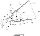
Fig. 2 is a cross-sectional view of a pressure probe in accordance with one embodiment to be used with the gas turbine engine ofFig. 1 , the pressure probe shown in a first position; -
Fig. 3 is another cross-sectional view of the pressure probe ofFig. 2 shown in a second position; and -
Fig. 4 is a top view of a pressure probe rake including a plurality of the pressure probes ofFig. 2 , some of the pressure probes having parts removed for illustration purposes. -
Fig. 1 illustrates an aircraft engine depicted as agas turbine engine 10 of a type preferably provided for use in subsonic flight, generally comprising in serial flow communication afan 12 through which ambient air is propelled, acompressor section 14 for pressurizing the air, acombustor 16 in which the compressed air is mixed with fuel and ignited for generating an annular stream of hot combustion gases, and aturbine section 18 for extracting energy from the combustion gases. Thefan 12, thecompressor section 14, and theturbine section 18 are rotatable about acentral axis 11 of thegas turbine engine 10. - In the embodiment shown, the
gas turbine engine 10 comprises a high-pressure spool having a high-pressure shaft 20 drivingly engaging a high-pressure turbine 18A of theturbine section 18 to a high-pressure compressor 14A of thecompressor section 14, and a low-pressure spool having a low-pressure shaft 21 drivingly engaging a low-pressure turbine 18B of the turbine section to a low-pressure compressor 14B of thecompressor section 14 and drivingly engaged to thefan 12. It will be understood that the contents of the present disclosure may be applicable to any suitable engines, such as turboprops and turboshafts, and reciprocating engines, such as piston and rotary engines without departing from the scope of the present disclosure. - In some cases, during flight or during experimental testing of the
gas turbine engine 10, it may be required to determine a total pressure of an air flow F0 moving through thegas turbine engine 10. To this extend apressure probe 30 may be used. Thepressure probe 30 may be located at any suitable locations. For instance, in the embodiment shown, thepressure probe 30 is located within abypass duct 22 located radially between anouter casing 23 and acore casing 24. However, thepressure probe 30 may be located at any other required locations. For instance, thepressure probe 30 may be located at a first location L1 upstream of thegas turbine engine 10 during bench testing of said engine; it may be located at a second location L2 between the low-pressure compressor 14B and the high-pressure compressor 14A; it may be located at a third location L3 downstream of thecombustor 16; it may be located at a fourth location L4 between the high-pressure turbine 18A and the low-pressure turbine 18B; it may be located at a fifth location L5 downstream of thegas turbine engine 10. Thepressure probe 30 may be located between stages of thecompressor section 14 or between stages of theturbine section 18. Thegas turbine engine 10 may be equipped with more than onepressure probe 30 distributed at many possible locations. - The
pressure probe 30 may be fluidly connected to apressure sensor 40 able to convert a pressure force into a signal indicative of a pressure. Thepressure sensor 40 may be operatively connected to acontroller 50 of thegas turbine engine 10. Thecontroller 50 may vary some operating parameters of thegas turbine engine 10 as a function of the pressure thereby measured. Thepressure sensor 40 may be operatively connected to a data acquisition system for engine testing purposes. - Referring now to
Fig. 2 , thepressure probe 30 is described in more detail. In the embodiment shown, thepressure probe 30 includes astatic member 31 and amovable member 32. As will be explained below, themovable member 32 to is able to move relative to thestatic member 31 to orient itself with the flow F0 flowing towards thepressure probe 30. Thepressure probe 30 has an inlet 30I and anoutlet 300. Theoutlet 300 is fluidly connected to the pressure sensor 40 (Fig. 1 ). The inlet 30I is oriented to receive air from the flow F0. - The measurement of stagnation pressure is usually made with a Pitot probe or Kiel head probe located in the free air stream. For best measurement quality, the stagnation pressure to be measured is as close as possible to the real value. The ratio of the measured value versus the real value, usually named recovery ratio, can vary between 0 and 1. For example, 0.99 indicates that 99% of the real pressure is effectively measured. The recovery characteristics can be evaluated with calibration tests. One of the factors that affects the recovery ratio is the angle of the air stream versus the probe angle. When the probe pressure hole is facing the air stream, recovery is optimal, and it decreases as incoming air angle increases. To reduce the loss of recovery, a Kiel head probe may be used to augment the incoming air angle range. With a Kiel head probe, stagnation pressure measurement is less sensitive to yaw/pitch angle. Yet a Kiel head also has its limits. Limits are characterized as an angle range (i.e. ±35°) where the measurement error in stagnation pressure is below a certain amount (i.e. <1% error). For turbine engine tests or aerodynamic tests, the Kiel head acceptance angle range may not be sufficient for all stagnation pressure measurement needs. This is true especially where the air stream angle can vary significantly (i.e., air stream behind variable guide vanes, air stream behind a rotor operating at various speeds and mass flows). There are other solutions like a five-hole probe. However, this type of probes requires specific calibration.
- The disclosed
pressure probe 30 may alleviate these drawbacks. Thepressure probe 30 disclosed herein may augment the acceptance angle at which the recovery is optimal by orienting itself to face the free air stream. It mechanically moves to face the flow. - Still referring to
Fig. 2 , thestatic member 31 includes aconduit 33 that is fluidly connected to theoutlet 300 of thepressure probe 30 and that leads to the pressure sensor 40 (Fig. 1 ). Asphere 34 is secured to an end of theconduit 33. Thesphere 34 may be hollow and defines a front face 31A and aback face 31B of thestatic member 31. A dashed line illustrates an imaginary separation between the front face 31A and theback face 31B. The front face 31A defines a curved surface 31C, which is herein of spherical shape but any suitable shape is contemplated. Thestatic member 31 has a static member inlet 31I at the front face 31A and astatic member outlet 310 at theback face 31B. The static member inlet 31I is fluidly connected to thestatic member outlet 310, which is itself fluidly connected to the pressure sensor 40 (Fig. 1 ) via theconduit 33. In the embodiment shown, the static member inlet 31I is defined by a plurality ofapertures 31D extending through the front face 31A. Theseapertures 31D may be equidistantly spaced from one another and uniformly distributed. Theback face 31B may be free of theapertures 31D. Each of theseapertures 31D is fluidly connected to thestatic member outlet 310 of thestatic member 31. - The
movable member 32 includes anengagement section 35 movably engaged to thestatic member 31. Themovable member 32 is movable relative to thestatic member 31 about a center of rotation R0. Themovable member 32 has a central axis A, which may intersect the center of rotation R0. Theengagement section 35 is matingly engaged to the front face 31A of thestatic member 31 to slide against the curved surface 31C. Stated differently, theengagement section 35 has a shape that substantially correspond to that of the curved surface 31C such that theengagement section 35 may move relative to the curved surface 31C. Theengagement section 35 is therefore matingly engaged to thesphere 34. Themovable member 32 may move relative to thestatic member 31 about a first direction D1 parallel to the central axis A, and about a plurality of directions normal to the central axis A, one of those directions, referred to below as a second direction D2, is illustrated with arrows inFig. 2 . - The
engagement section 35 has anopening 35A shown with a dashed line. Theopening 35A is used for receiving the flow F0 and is fluidly connected to the static member inlet 31I, herein theapertures 31D, of thestatic member 31. As shown inFig. 2 , theopening 35A may be in register with more than one of theapertures 31D regardless of the position of themovable member 32 relative to thestatic member 31. This may ensure that thepressure sensor 40 is suitably exposed to the air pressure of the flow F0. - The
movable member 32 may include aconduit section 36 protruding from theengagement section 35 along the central axis A. Theconduit section 36 may be located forward of the center of rotation R0 relative to the direction of the flow F0. Theconduit section 36 and theengagement section 35 are shown herein as being monolithic parts of a single body, but may be two separate parts secured (e.g., fastened, welded) together. Theconduit section 36 has a conduit inlet 36I and aconduit outlet 360 fluidly connected to the conduit inlet 36I and to theopening 35A of theengagement section 35. Thus, air enters theconduit section 36 via the conduit inlet 36I, exits theconduit section 36 via theconduit outlet 360 and flows within theengagement section 35 via theopening 35A to reach theapertures 31D of thestatic member 31. Theconduit section 36 has achamfer 36A at the conduit inlet 36I. Thischamfer 36A may help in increasing a range of angle between the flow F0 and the central axis A. - To orient the
movable member 32 relative to thestatic member 31 such that theopening 35A of theengagement section 35, and herein the conduit inlet 36I of theconduit section 36, are aligned parallel to the direction of the flow F0, thepressure probe 30 includes anorientation section 37, also referred to as a skirt. Theorientation section 37 protrudes from theengagement section 35 along the central axis A and is located rearward of the center of rotation R0 relative to the direction of the flow F0. Theorientation section 37 and theengagement section 35 may be parts of a single monolithic body or, as shown herein, may be connected together via a threadedconnection 38. The threadedconnection 38 may be replaced by any connection means such as, for instance, snap fit, fasteners, tongue and groove, welding, and so on. - The
orientation section 37 defines anexternal surface 37A that faces away from the central axis A and that is exposed to the flow F0. Theorientation section 37 has herein a frustoconical shape and flares away from the central axis A in a direction of the flow F0, but any other suitable shape is contemplated. Theorientation section 37 defines an opening angle A3 that may be about 45 degrees. The angle A3 may vary from 20 to 50 degrees. The angle A3 may be selected to meet air flow angle needs. In some cases, the opening angle A3 may be zero or less than zero. Theexternal surface 37A extends circumferentially around the central axis A. In the embodiment shown, theexternal surface 37A extends about a full circumference around the central axis A. Alternatively, theexternal surface 37A may be defined by a plurality of tabs or fins circumferentially distributed about the central axis A. Theexternal surface 37A may define a plurality of apertures such as to reduce a drag exerted on the flow F0 by theorientation section 37. Theexternal surface 37A may be axisymmetric about the central axis A. It will be appreciated that an area of theexternal surface 37A contacted with the flow F0 may be greater than that of an external surface of theconduit section 36. - Referring to
Figs. 2 and3 , in use, themovable member 32 is movable relative to thestatic member 31 from a first position (Fig. 2 ) to a second position (Fig. 3 ) as a result of a force imparted by the flow F0 on theexternal surface 37A. It will be appreciated that themovable member 32 may be located at a plurality of positions relative to thestatic member 31. In other words, when the central axis A is non-parallel to the flow F0, a force of the flow F0 exerted on theexternal surface 37A of theorientation section 37 is non-axisymmetric. Stated differently, theexternal surface 37A is oriented such as to be intersected by the flow F0 at least when the central axis A is non-parallel to the flow F0 to move themovable member 32 relative to thestatic member 31 from the first position to the second position. That is, inFig. 2 , the force exerted by the flow F0 on a lower half of theexternal surface 37A may be greater than that exerted on an upper half of theexternal surface 37A. In turn, this force on theexternal surface 37A of theorientation section 37 creates a moment on themovable member 32 about the center of rotation R0 to pivot themovable member 32 from the first position ofFig. 2 to the second position ofFig. 3 in which the force exerted on theexternal surface 37A may be axisymmetric. In some embodiments, a difference between maximal and minimal forces exerted on theexternal surface 37A is reduced by moving themovable member 32 from the first position to the second position. In some cases, it may not be possible to make the force axisymmetric and theorientation section 37 may abut against theconduit 33. - Still referring to
Figs. 2-3 , a first angle A1 defined between the central axis A and the flow F0 in the first position of themovable member 32 is different than a second angle A2 defined between the central axis A and the flow F0 in the second position of themovable member 32. Herein, the second angle A2 is less than the first angle A1. Herein, the second angle A2 may be zero such that the central axis A is parallel to the flow F0. Stated differently, the angle between the flow F0 and the central axis A decreases form the first position to the second position. Theorientation section 37 may therefore act as a parachute to passively orient themovable member 32 parallel, or as close as possible to a parallel orientation, to the flow F0 to minimize a drag force exerted on themovable member 32 by the flow F0. Put differently, thepressure probe 30 is non-actuated and themovable member 32 is free from engagement with an actuator. - As shown in
Fig. 2 , aseal 39, such as an O-ring, is disposed between thesphere 34 and themovable member 32. Theseal 39 may be secured to themovable member 32 proximate where theorientation section 37 is secured to theengagement section 35. Theseal 39 rides against theback face 31B of thestatic member 31; said back face 31B being defined by thesphere 34 in the present embodiment. Thus, theseal 39 seals a gap between themovable member 32 and thesphere 34. Theseal 39 may therefore ensure that all of the air that enters the inlet 30I of thepressure probe 30 reaches the pressure sensor 40 (Fig. 1 ). Moreover, all of theapertures 31D are located on the front face 31A of themovable member 32; the front face 31A defined by thesphere 34. Theback face 31B is free of theapertures 31D. In other words, the surface of thesphere 34 that is in contact with theseal 39 when themovable member 32 moves relative to thestatic member 31 is free of theapertures 31D. This may ensure that none of theapertures 31D is located rearward of theseal 39 to avoid air not reaching thepressure sensor 40. Other means of sealing could be employed with respect to the manufacturing characteristics. Small aft leakage could be acceptable as long as the recovery ratio stays optimal. In some embodiments, theseal 39 may be omitted if the "sphericity" of the contact area between theback face 31B and theorientation section 37 is significant enough to only allow a negligible air leak between the two. This air leak should be negligible enough so that it does not reduce the quality of the stagnation pressure measurement. Theorientation section 37 angle A3 may be adjusted to meet the angle range needed. Theorientation section 37 may be plain or perforated to achieve the self-facing performance required function of size, Mach number, density, fluid type. - Referring now to
Fig. 4 , a pressure probe rake is shown at 60. Therake 60 includes a frame 61 onto which are secured a plurality, three in the embodiment shown, but more or less may be used, of the pressure probes 30 described above. Each of these pressure probes 30 is fluidly connected to arespective pressure sensor 40. - Once all assembled, when the probe is inserted in a free air stream, it aligns itself to face the flow. If the flow angle is higher than the mechanical angle that the probe can moves, the impact tube itself can accept an additional angle range with optimal recovery ratio from that mechanical angle position.
- In an alternate embodiment, the
pressure probe 30 may be movable solely in one direction (e.g., pitch or yaw). The probe sphere size may be as small as few millimeters or bigger for structural integrity and available space. - The
pressure probe 30 andpressure probe rake 60 may be installed in the free air stream upstream or downstream of thegas turbine engine 10. In some cases, thepressure probe 30 andpressure probe rake 60 may be installed within the engine at locations where determining the total pressure is required. - The disclosed
pressure probe 30 may also be used for other types of aerodynamics or fluid dynamics testing. Like aircrafts, cars, wind tunnel tests, and so on. - The embodiments described in this document provide non-limiting examples of possible implementations of the present technology. Upon review of the present disclosure, a person of ordinary skill in the art will recognize that changes may be made to the embodiments described herein without departing from the scope of the present technology. Yet further modifications could be implemented by a person of ordinary skill in the art in view of the present disclosure, which modifications would be within the scope of the present technology.
Claims (11)
- A pressure probe (30) for measuring a total pressure of a flow (F0), comprising:a static member (31) having a front face (31A) facing the flow (F0) and a back face (31B) opposed to the front face (31A), an inlet (31I) at the front face (31A) and an outlet (310) at the back face (31B), the outlet (310) fluidly connected to the inlet (31I) and connectable to a pressure sensor (40), the front face (31A) defining a curved surface (31C);a movable member (32) movably engaged to the static member (31), the movable member (32) movable relative to the static member (31) about a center of rotation (R0) of the movable member (32), the movable member (32) having a central axis (A), the movable member (32) comprising:an engagement section (35) matingly engaged to the front face (31A) to slide against the curved surface (31C), the engagement section (35) having an opening (35A) for receiving the flow (F0) and fluidly connected to the inlet (31I) of the static member (31); andan orientation section (37) protruding from the engagement section (35) along the central axis (A) and located rearward of the center of rotation (R0) relative to a direction of the flow (F0), the orientation section (37) defining an external surface (37A) exposed to the flow (F0), facing away from the central axis (A), and extending circumferentially around the central axis (A).
- The pressure probe (30) of claim 1, wherein the movable member (32) is movable relative to the static member (31) from a first position in which a force exerted by the flow (F0) on the external surface (37A) is non-axisymmetric thereby creating a moment on the movable member (32) about the center of rotation (R0) to a second position in which the force is axisymmetric.
- The pressure probe (30) of claim 1 or 2, wherein the external surface (37A) is oriented such as to be intersected by the flow (F0) at least when the central axis (A) is non-parallel to the flow (F0) to move the movable member (32) relative to the static member (31).
- The pressure probe (30) of any of the preceding claims, comprising a conduit section (36) protruding from the engagement section (35) along the central axis (A) and located forward of the center of rotation (R0), the conduit section (36) having a conduit inlet (36I) for receiving the flow (F0) and a conduit outlet (360) fluidly connected to the opening (35A) and to the inlet (31I) of the static member (31).
- The pressure probe (30) of any of the preceding claims, wherein the inlet (31I) of the static member (31) is defined by a plurality of apertures (31D) extending through the curved surface (31C).
- The pressure probe (30) of claim 5, wherein more than one of the plurality of apertures (31D) are in register with an opening (35A) of the engagement section (35) at a plurality of positions of the movable member (32) relative to the static member (31).
- The pressure probe (30) of any of the preceding claims, wherein the static member (31) includes a sphere (34) disposed at an end of a conduit (33) leading to the pressure sensor (40), the curved surface (31C) defined by the sphere (34), the engagement section (35) matingly engaged to the sphere (34).
- The pressure probe (30) of claim 7, wherein the sphere (34) is hollow.
- The pressure probe (30) of claim 7 or 8, wherein the back face (31B) is defined by the sphere (34), a seal (39) secured to the movable member (32) to seal a gap defined between the back face (31B) and the movable member (32).
- The pressure probe (30) of any of the preceding claims, wherein the movable member (32) has a frustoconical shape and flares away from the central axis (A) in a direction of the flow (F0).
- An aircraft engine (10) comprising a pressure probe (30) according to any of the preceding claims.
Applications Claiming Priority (1)
| Application Number | Priority Date | Filing Date | Title |
|---|---|---|---|
| US17/933,134 US11692455B1 (en) | 2022-09-19 | 2022-09-19 | Passively orientable pressure probe |
Publications (1)
| Publication Number | Publication Date |
|---|---|
| EP4343120A1 true EP4343120A1 (en) | 2024-03-27 |
Family
ID=86993240
Family Applications (1)
| Application Number | Title | Priority Date | Filing Date |
|---|---|---|---|
| EP23198052.5A Pending EP4343120A1 (en) | 2022-09-19 | 2023-09-18 | Passively orientable pressure probe |
Country Status (3)
| Country | Link |
|---|---|
| US (1) | US11692455B1 (en) |
| EP (1) | EP4343120A1 (en) |
| CA (1) | CA3210493A1 (en) |
Citations (3)
| Publication number | Priority date | Publication date | Assignee | Title |
|---|---|---|---|---|
| US4733975A (en) * | 1986-07-03 | 1988-03-29 | The United States Of America As Represented By The Secretary Of The Air Force | Unitized high temperature probes |
| US20160115871A1 (en) * | 2014-10-24 | 2016-04-28 | United Technologies Corporation | Cooling configuration for a component |
| US20160363608A1 (en) * | 2015-06-12 | 2016-12-15 | Rolls-Royce Deutschland Ltd & Co Kg | Measuring device and unit having such a measuring device |
Family Cites Families (9)
| Publication number | Priority date | Publication date | Assignee | Title |
|---|---|---|---|---|
| GB759268A (en) * | 1953-07-14 | 1956-10-17 | Power Jets Res & Dev Ltd | Method of mounting instruments in turbines and compressors |
| US4244222A (en) * | 1979-02-01 | 1981-01-13 | General Electric Company | Instrumentation probe |
| US4433584A (en) | 1981-11-27 | 1984-02-28 | United Technologies Corp. | Total pressure probe |
| US4823615A (en) * | 1987-11-04 | 1989-04-25 | Preso Industries | Self-averaging pitot tube probe and method for measuring fluid flow |
| US6487918B1 (en) * | 2000-12-22 | 2002-12-03 | Mestek, Inc. | Airflow sensor for averaging total pressure |
| CA2504074C (en) * | 2005-04-13 | 2013-10-22 | E. H. Price Limited | Airflow sensor |
| US9856743B2 (en) * | 2014-05-28 | 2018-01-02 | Safran Aircraft Engines | Instrumented flow passage of a turbine engine |
| FR3066779B1 (en) * | 2017-05-26 | 2020-04-03 | Safran Aircraft Engines | DEVICE FOR MEASURING PARAMETERS OF AN AERODYNAMIC FLOW FOR A TURBOMACHINE BLADE, BLADE AND A TURBOMACHINE BLADE EQUIPPED WITH SAID MEASUREMENT DEVICE |
| KR102785327B1 (en) | 2019-05-17 | 2025-03-25 | 한화에어로스페이스 주식회사 | Rake apparatus |
-
2022
- 2022-09-19 US US17/933,134 patent/US11692455B1/en active Active
-
2023
- 2023-08-29 CA CA3210493A patent/CA3210493A1/en active Pending
- 2023-09-18 EP EP23198052.5A patent/EP4343120A1/en active Pending
Patent Citations (3)
| Publication number | Priority date | Publication date | Assignee | Title |
|---|---|---|---|---|
| US4733975A (en) * | 1986-07-03 | 1988-03-29 | The United States Of America As Represented By The Secretary Of The Air Force | Unitized high temperature probes |
| US20160115871A1 (en) * | 2014-10-24 | 2016-04-28 | United Technologies Corporation | Cooling configuration for a component |
| US20160363608A1 (en) * | 2015-06-12 | 2016-12-15 | Rolls-Royce Deutschland Ltd & Co Kg | Measuring device and unit having such a measuring device |
Also Published As
| Publication number | Publication date |
|---|---|
| US11692455B1 (en) | 2023-07-04 |
| CA3210493A1 (en) | 2024-03-19 |
Similar Documents
| Publication | Publication Date | Title |
|---|---|---|
| US11879343B2 (en) | Systems for controlling variable outlet guide vanes | |
| US8209953B2 (en) | Gas turbine engine system providing simulated boundary layer thickness increase | |
| EP0186609B1 (en) | Temperature probe | |
| CN110475947B (en) | Pressure sensor assembly for a turbine engine | |
| US20120110979A1 (en) | Flutter sensing system for a gas turbine engine | |
| EP3620630B1 (en) | Method and system for separated flow detection | |
| EP4006315B1 (en) | Variable orientation guide vane for a gas turbine engine, and method of operating adjacent variable orientation first and second vanes disposed in an annular gas path of a gas turbine engine | |
| EP4177442B1 (en) | Air inlet strut for aircraft engine | |
| US12398648B2 (en) | Segmented variable fan outlet guide vane with cam assembly and pass through actuation mechanisms | |
| JP6505179B2 (en) | Exhaust gas temperature detection probe assembly | |
| EP4343120A1 (en) | Passively orientable pressure probe | |
| Krone et al. | Atmospheric crosswind tests of aspirated jet engine intake models | |
| US12546231B2 (en) | High-pressure rotor control system | |
| Campbell et al. | Preliminary evaluation of turbine performance with variable-area turbine nozzles in a turbojet engine | |
| CN115436009B (en) | Jet pipe thrust measurement test system with integrally designed afterbody and jet pipe | |
| Herrmann et al. | Experimental study of chin intakes for airbreathing missiles with high agility | |
| US12146413B1 (en) | Circumferentially variable flow control in fan outlet guide vane assemblies for distortion management and stall margin in gas turbine engines | |
| EP0907004B1 (en) | Arrangement of a gas temperature sensing device in a gas turbine vane | |
| US12276229B2 (en) | Method of operating a turbine engine having a bleed system | |
| US12312997B2 (en) | Turbine engine having a bleed system | |
| EP4696878A1 (en) | Gas turbine engine nozzle with variable area | |
| US20250257689A1 (en) | Bleed-off assembly intake device for an aircraft propulsion system | |
| Lueders | Experimental investigation of advanced concepts to increase turbine blade loading. Volume 5-Performance evaluation of jet-flap rotor blade | |
| Herrmann et al. | Influence of intake orientation on ramjet performance | |
| Martin | Investigation of normal shock inlets for highly maneuverable aircraft |
Legal Events
| Date | Code | Title | Description |
|---|---|---|---|
| PUAI | Public reference made under article 153(3) epc to a published international application that has entered the european phase |
Free format text: ORIGINAL CODE: 0009012 |
|
| STAA | Information on the status of an ep patent application or granted ep patent |
Free format text: STATUS: THE APPLICATION HAS BEEN PUBLISHED |
|
| AK | Designated contracting states |
Kind code of ref document: A1 Designated state(s): AL AT BE BG CH CY CZ DE DK EE ES FI FR GB GR HR HU IE IS IT LI LT LU LV MC ME MK MT NL NO PL PT RO RS SE SI SK SM TR |
|
| STAA | Information on the status of an ep patent application or granted ep patent |
Free format text: STATUS: REQUEST FOR EXAMINATION WAS MADE |
|
| 17P | Request for examination filed |
Effective date: 20240925 |
|
| RBV | Designated contracting states (corrected) |
Designated state(s): AL AT BE BG CH CY CZ DE DK EE ES FI FR GB GR HR HU IE IS IT LI LT LU LV MC ME MK MT NL NO PL PT RO RS SE SI SK SM TR |
|
| GRAP | Despatch of communication of intention to grant a patent |
Free format text: ORIGINAL CODE: EPIDOSNIGR1 |
|
| STAA | Information on the status of an ep patent application or granted ep patent |
Free format text: STATUS: GRANT OF PATENT IS INTENDED |
|
| INTG | Intention to grant announced |
Effective date: 20251208 |
|
| RAP3 | Party data changed (applicant data changed or rights of an application transferred) |
Owner name: PRATT & WHITNEY CANADA CORP. |
|
| RIN1 | Information on inventor provided before grant (corrected) |
Inventor name: DOUCET, FREDERIC |
|
| GRAS | Grant fee paid |
Free format text: ORIGINAL CODE: EPIDOSNIGR3 |
|
| GRAA | (expected) grant |
Free format text: ORIGINAL CODE: 0009210 |
|
| STAA | Information on the status of an ep patent application or granted ep patent |
Free format text: STATUS: THE PATENT HAS BEEN GRANTED |