EP4343117A1 - Method for coating a tip of an aerofoil of a gas turbine engine - Google Patents
Method for coating a tip of an aerofoil of a gas turbine engine Download PDFInfo
- Publication number
- EP4343117A1 EP4343117A1 EP23195970.1A EP23195970A EP4343117A1 EP 4343117 A1 EP4343117 A1 EP 4343117A1 EP 23195970 A EP23195970 A EP 23195970A EP 4343117 A1 EP4343117 A1 EP 4343117A1
- Authority
- EP
- European Patent Office
- Prior art keywords
- tip
- aerofoil
- nickel
- gamma
- layer
- Prior art date
- Legal status (The legal status is an assumption and is not a legal conclusion. Google has not performed a legal analysis and makes no representation as to the accuracy of the status listed.)
- Withdrawn
Links
- 238000000576 coating method Methods 0.000 title claims abstract description 105
- 239000011248 coating agent Substances 0.000 title claims abstract description 102
- 238000000034 method Methods 0.000 title claims abstract description 39
- PXHVJJICTQNCMI-UHFFFAOYSA-N Nickel Chemical compound [Ni] PXHVJJICTQNCMI-UHFFFAOYSA-N 0.000 claims abstract description 230
- 229910052759 nickel Inorganic materials 0.000 claims abstract description 114
- 238000000151 deposition Methods 0.000 claims abstract description 81
- 238000010438 heat treatment Methods 0.000 claims abstract description 68
- 239000002245 particle Substances 0.000 claims abstract description 65
- 239000011159 matrix material Substances 0.000 claims abstract description 55
- 238000009713 electroplating Methods 0.000 claims description 35
- 230000008021 deposition Effects 0.000 claims description 20
- 239000010941 cobalt Substances 0.000 claims description 19
- 229910017052 cobalt Inorganic materials 0.000 claims description 19
- GUTLYIVDDKVIGB-UHFFFAOYSA-N cobalt atom Chemical compound [Co] GUTLYIVDDKVIGB-UHFFFAOYSA-N 0.000 claims description 19
- 239000004411 aluminium Substances 0.000 claims description 14
- 229910052782 aluminium Inorganic materials 0.000 claims description 14
- XAGFODPZIPBFFR-UHFFFAOYSA-N aluminium Chemical compound [Al] XAGFODPZIPBFFR-UHFFFAOYSA-N 0.000 claims description 14
- 239000011651 chromium Substances 0.000 claims description 14
- 239000010936 titanium Substances 0.000 claims description 13
- VYZAMTAEIAYCRO-UHFFFAOYSA-N Chromium Chemical compound [Cr] VYZAMTAEIAYCRO-UHFFFAOYSA-N 0.000 claims description 12
- 229910052804 chromium Inorganic materials 0.000 claims description 12
- 238000001816 cooling Methods 0.000 claims description 12
- 230000006698 induction Effects 0.000 claims description 12
- 229910052719 titanium Inorganic materials 0.000 claims description 12
- RTAQQCXQSZGOHL-UHFFFAOYSA-N Titanium Chemical compound [Ti] RTAQQCXQSZGOHL-UHFFFAOYSA-N 0.000 claims description 11
- 229910052715 tantalum Inorganic materials 0.000 claims description 10
- GUVRBAGPIYLISA-UHFFFAOYSA-N tantalum atom Chemical compound [Ta] GUVRBAGPIYLISA-UHFFFAOYSA-N 0.000 claims description 10
- 229910052582 BN Inorganic materials 0.000 claims description 6
- PZNSFCLAULLKQX-UHFFFAOYSA-N Boron nitride Chemical compound N#B PZNSFCLAULLKQX-UHFFFAOYSA-N 0.000 claims description 6
- 238000004093 laser heating Methods 0.000 claims description 4
- 239000007789 gas Substances 0.000 description 36
- 239000000463 material Substances 0.000 description 28
- 238000007747 plating Methods 0.000 description 16
- 239000008151 electrolyte solution Substances 0.000 description 13
- 230000007704 transition Effects 0.000 description 8
- 239000013078 crystal Substances 0.000 description 5
- 239000000843 powder Substances 0.000 description 5
- 230000015572 biosynthetic process Effects 0.000 description 4
- 229910000601 superalloy Inorganic materials 0.000 description 4
- 238000002485 combustion reaction Methods 0.000 description 3
- 239000002131 composite material Substances 0.000 description 3
- 230000003647 oxidation Effects 0.000 description 3
- 238000007254 oxidation reaction Methods 0.000 description 3
- 230000001141 propulsive effect Effects 0.000 description 3
- 230000009467 reduction Effects 0.000 description 3
- 238000011144 upstream manufacturing Methods 0.000 description 3
- 229910052727 yttrium Inorganic materials 0.000 description 3
- VWQVUPCCIRVNHF-UHFFFAOYSA-N yttrium atom Chemical group [Y] VWQVUPCCIRVNHF-UHFFFAOYSA-N 0.000 description 3
- XKRFYHLGVUSROY-UHFFFAOYSA-N Argon Chemical compound [Ar] XKRFYHLGVUSROY-UHFFFAOYSA-N 0.000 description 2
- IJGRMHOSHXDMSA-UHFFFAOYSA-N Atomic nitrogen Chemical compound N#N IJGRMHOSHXDMSA-UHFFFAOYSA-N 0.000 description 2
- XEEYBQQBJWHFJM-UHFFFAOYSA-N Iron Chemical compound [Fe] XEEYBQQBJWHFJM-UHFFFAOYSA-N 0.000 description 2
- 229910052779 Neodymium Inorganic materials 0.000 description 2
- 239000000919 ceramic Substances 0.000 description 2
- 230000006835 compression Effects 0.000 description 2
- 238000007906 compression Methods 0.000 description 2
- 239000002223 garnet Substances 0.000 description 2
- 239000011521 glass Substances 0.000 description 2
- 238000009413 insulation Methods 0.000 description 2
- 239000000203 mixture Substances 0.000 description 2
- QEFYFXOXNSNQGX-UHFFFAOYSA-N neodymium atom Chemical compound [Nd] QEFYFXOXNSNQGX-UHFFFAOYSA-N 0.000 description 2
- HBMJWWWQQXIZIP-UHFFFAOYSA-N silicon carbide Chemical compound [Si+]#[C-] HBMJWWWQQXIZIP-UHFFFAOYSA-N 0.000 description 2
- 229910000951 Aluminide Chemical group 0.000 description 1
- OKTJSMMVPCPJKN-UHFFFAOYSA-N Carbon Chemical compound [C] OKTJSMMVPCPJKN-UHFFFAOYSA-N 0.000 description 1
- ZOKXTWBITQBERF-UHFFFAOYSA-N Molybdenum Chemical compound [Mo] ZOKXTWBITQBERF-UHFFFAOYSA-N 0.000 description 1
- 229910052769 Ytterbium Inorganic materials 0.000 description 1
- 239000003082 abrasive agent Substances 0.000 description 1
- 229910052786 argon Inorganic materials 0.000 description 1
- 230000009286 beneficial effect Effects 0.000 description 1
- 229910052799 carbon Inorganic materials 0.000 description 1
- 238000005260 corrosion Methods 0.000 description 1
- 230000007797 corrosion Effects 0.000 description 1
- 239000000835 fiber Substances 0.000 description 1
- 239000000446 fuel Substances 0.000 description 1
- 239000001307 helium Substances 0.000 description 1
- 229910052734 helium Inorganic materials 0.000 description 1
- SWQJXJOGLNCZEY-UHFFFAOYSA-N helium atom Chemical compound [He] SWQJXJOGLNCZEY-UHFFFAOYSA-N 0.000 description 1
- 229910052742 iron Inorganic materials 0.000 description 1
- 229910052746 lanthanum Inorganic materials 0.000 description 1
- FZLIPJUXYLNCLC-UHFFFAOYSA-N lanthanum atom Chemical group [La] FZLIPJUXYLNCLC-UHFFFAOYSA-N 0.000 description 1
- 229910001092 metal group alloy Inorganic materials 0.000 description 1
- 239000011156 metal matrix composite Substances 0.000 description 1
- 230000004048 modification Effects 0.000 description 1
- 238000012986 modification Methods 0.000 description 1
- 229910052750 molybdenum Inorganic materials 0.000 description 1
- 239000011733 molybdenum Substances 0.000 description 1
- KERTUBUCQCSNJU-UHFFFAOYSA-L nickel(2+);disulfamate Chemical compound [Ni+2].NS([O-])(=O)=O.NS([O-])(=O)=O KERTUBUCQCSNJU-UHFFFAOYSA-L 0.000 description 1
- 229910052757 nitrogen Inorganic materials 0.000 description 1
- 239000002244 precipitate Substances 0.000 description 1
- 230000001376 precipitating effect Effects 0.000 description 1
- 239000000047 product Substances 0.000 description 1
- 229910052761 rare earth metal Chemical group 0.000 description 1
- 150000002910 rare earth metals Chemical group 0.000 description 1
- 229910010271 silicon carbide Inorganic materials 0.000 description 1
- 239000006104 solid solution Substances 0.000 description 1
- 238000005728 strengthening Methods 0.000 description 1
- 239000012720 thermal barrier coating Substances 0.000 description 1
- WFKWXMTUELFFGS-UHFFFAOYSA-N tungsten Chemical compound [W] WFKWXMTUELFFGS-UHFFFAOYSA-N 0.000 description 1
- 229910052721 tungsten Inorganic materials 0.000 description 1
- 239000010937 tungsten Substances 0.000 description 1
- NAWDYIZEMPQZHO-UHFFFAOYSA-N ytterbium Chemical group [Yb] NAWDYIZEMPQZHO-UHFFFAOYSA-N 0.000 description 1
Images




Classifications
-
- F—MECHANICAL ENGINEERING; LIGHTING; HEATING; WEAPONS; BLASTING
- F01—MACHINES OR ENGINES IN GENERAL; ENGINE PLANTS IN GENERAL; STEAM ENGINES
- F01D—NON-POSITIVE DISPLACEMENT MACHINES OR ENGINES, e.g. STEAM TURBINES
- F01D5/00—Blades; Blade-carrying members; Heating, heat-insulating, cooling or antivibration means on the blades or the members
- F01D5/12—Blades
- F01D5/28—Selecting particular materials; Particular measures relating thereto; Measures against erosion or corrosion
- F01D5/288—Protective coatings for blades
-
- F—MECHANICAL ENGINEERING; LIGHTING; HEATING; WEAPONS; BLASTING
- F01—MACHINES OR ENGINES IN GENERAL; ENGINE PLANTS IN GENERAL; STEAM ENGINES
- F01D—NON-POSITIVE DISPLACEMENT MACHINES OR ENGINES, e.g. STEAM TURBINES
- F01D5/00—Blades; Blade-carrying members; Heating, heat-insulating, cooling or antivibration means on the blades or the members
- F01D5/12—Blades
- F01D5/28—Selecting particular materials; Particular measures relating thereto; Measures against erosion or corrosion
- F01D5/286—Particular treatment of blades, e.g. to increase durability or resistance against corrosion or erosion
-
- C—CHEMISTRY; METALLURGY
- C22—METALLURGY; FERROUS OR NON-FERROUS ALLOYS; TREATMENT OF ALLOYS OR NON-FERROUS METALS
- C22C—ALLOYS
- C22C19/00—Alloys based on nickel or cobalt
-
- C—CHEMISTRY; METALLURGY
- C25—ELECTROLYTIC OR ELECTROPHORETIC PROCESSES; APPARATUS THEREFOR
- C25D—PROCESSES FOR THE ELECTROLYTIC OR ELECTROPHORETIC PRODUCTION OF COATINGS; ELECTROFORMING; APPARATUS THEREFOR
- C25D13/00—Electrophoretic coating characterised by the process
- C25D13/02—Electrophoretic coating characterised by the process with inorganic material
-
- C—CHEMISTRY; METALLURGY
- C25—ELECTROLYTIC OR ELECTROPHORETIC PROCESSES; APPARATUS THEREFOR
- C25D—PROCESSES FOR THE ELECTROLYTIC OR ELECTROPHORETIC PRODUCTION OF COATINGS; ELECTROFORMING; APPARATUS THEREFOR
- C25D15/00—Electrolytic or electrophoretic production of coatings containing embedded materials, e.g. particles, whiskers, wires
-
- C—CHEMISTRY; METALLURGY
- C25—ELECTROLYTIC OR ELECTROPHORETIC PROCESSES; APPARATUS THEREFOR
- C25D—PROCESSES FOR THE ELECTROLYTIC OR ELECTROPHORETIC PRODUCTION OF COATINGS; ELECTROFORMING; APPARATUS THEREFOR
- C25D5/00—Electroplating characterised by the process; Pretreatment or after-treatment of workpieces
- C25D5/10—Electroplating with more than one layer of the same or of different metals
- C25D5/12—Electroplating with more than one layer of the same or of different metals at least one layer being of nickel or chromium
-
- C—CHEMISTRY; METALLURGY
- C25—ELECTROLYTIC OR ELECTROPHORETIC PROCESSES; APPARATUS THEREFOR
- C25D—PROCESSES FOR THE ELECTROLYTIC OR ELECTROPHORETIC PRODUCTION OF COATINGS; ELECTROFORMING; APPARATUS THEREFOR
- C25D5/00—Electroplating characterised by the process; Pretreatment or after-treatment of workpieces
- C25D5/10—Electroplating with more than one layer of the same or of different metals
- C25D5/12—Electroplating with more than one layer of the same or of different metals at least one layer being of nickel or chromium
- C25D5/14—Electroplating with more than one layer of the same or of different metals at least one layer being of nickel or chromium two or more layers being of nickel or chromium, e.g. duplex or triplex layers
-
- C—CHEMISTRY; METALLURGY
- C25—ELECTROLYTIC OR ELECTROPHORETIC PROCESSES; APPARATUS THEREFOR
- C25D—PROCESSES FOR THE ELECTROLYTIC OR ELECTROPHORETIC PRODUCTION OF COATINGS; ELECTROFORMING; APPARATUS THEREFOR
- C25D7/00—Electroplating characterised by the article coated
- C25D7/008—Thermal barrier coatings
-
- F—MECHANICAL ENGINEERING; LIGHTING; HEATING; WEAPONS; BLASTING
- F01—MACHINES OR ENGINES IN GENERAL; ENGINE PLANTS IN GENERAL; STEAM ENGINES
- F01D—NON-POSITIVE DISPLACEMENT MACHINES OR ENGINES, e.g. STEAM TURBINES
- F01D11/00—Preventing or minimising internal leakage of working-fluid, e.g. between stages
- F01D11/08—Preventing or minimising internal leakage of working-fluid, e.g. between stages for sealing space between rotor blade tips and stator
- F01D11/12—Preventing or minimising internal leakage of working-fluid, e.g. between stages for sealing space between rotor blade tips and stator using a rubstrip, e.g. erodible. deformable or resiliently-biased part
- F01D11/122—Preventing or minimising internal leakage of working-fluid, e.g. between stages for sealing space between rotor blade tips and stator using a rubstrip, e.g. erodible. deformable or resiliently-biased part with erodable or abradable material
-
- F—MECHANICAL ENGINEERING; LIGHTING; HEATING; WEAPONS; BLASTING
- F01—MACHINES OR ENGINES IN GENERAL; ENGINE PLANTS IN GENERAL; STEAM ENGINES
- F01D—NON-POSITIVE DISPLACEMENT MACHINES OR ENGINES, e.g. STEAM TURBINES
- F01D5/00—Blades; Blade-carrying members; Heating, heat-insulating, cooling or antivibration means on the blades or the members
- F01D5/12—Blades
- F01D5/14—Form or construction
- F01D5/20—Specially-shaped blade tips to seal space between tips and stator
-
- F—MECHANICAL ENGINEERING; LIGHTING; HEATING; WEAPONS; BLASTING
- F05—INDEXING SCHEMES RELATING TO ENGINES OR PUMPS IN VARIOUS SUBCLASSES OF CLASSES F01-F04
- F05D—INDEXING SCHEME FOR ASPECTS RELATING TO NON-POSITIVE-DISPLACEMENT MACHINES OR ENGINES, GAS-TURBINES OR JET-PROPULSION PLANTS
- F05D2230/00—Manufacture
- F05D2230/30—Manufacture with deposition of material
- F05D2230/31—Layer deposition
-
- F—MECHANICAL ENGINEERING; LIGHTING; HEATING; WEAPONS; BLASTING
- F05—INDEXING SCHEMES RELATING TO ENGINES OR PUMPS IN VARIOUS SUBCLASSES OF CLASSES F01-F04
- F05D—INDEXING SCHEME FOR ASPECTS RELATING TO NON-POSITIVE-DISPLACEMENT MACHINES OR ENGINES, GAS-TURBINES OR JET-PROPULSION PLANTS
- F05D2230/00—Manufacture
- F05D2230/40—Heat treatment
-
- F—MECHANICAL ENGINEERING; LIGHTING; HEATING; WEAPONS; BLASTING
- F05—INDEXING SCHEMES RELATING TO ENGINES OR PUMPS IN VARIOUS SUBCLASSES OF CLASSES F01-F04
- F05D—INDEXING SCHEME FOR ASPECTS RELATING TO NON-POSITIVE-DISPLACEMENT MACHINES OR ENGINES, GAS-TURBINES OR JET-PROPULSION PLANTS
- F05D2230/00—Manufacture
- F05D2230/90—Coating; Surface treatment
-
- F—MECHANICAL ENGINEERING; LIGHTING; HEATING; WEAPONS; BLASTING
- F05—INDEXING SCHEMES RELATING TO ENGINES OR PUMPS IN VARIOUS SUBCLASSES OF CLASSES F01-F04
- F05D—INDEXING SCHEME FOR ASPECTS RELATING TO NON-POSITIVE-DISPLACEMENT MACHINES OR ENGINES, GAS-TURBINES OR JET-PROPULSION PLANTS
- F05D2240/00—Components
- F05D2240/10—Stators
- F05D2240/15—Heat shield
-
- F—MECHANICAL ENGINEERING; LIGHTING; HEATING; WEAPONS; BLASTING
- F05—INDEXING SCHEMES RELATING TO ENGINES OR PUMPS IN VARIOUS SUBCLASSES OF CLASSES F01-F04
- F05D—INDEXING SCHEME FOR ASPECTS RELATING TO NON-POSITIVE-DISPLACEMENT MACHINES OR ENGINES, GAS-TURBINES OR JET-PROPULSION PLANTS
- F05D2260/00—Function
- F05D2260/94—Functionality given by mechanical stress related aspects such as low cycle fatigue [LCF] of high cycle fatigue [HCF]
- F05D2260/941—Functionality given by mechanical stress related aspects such as low cycle fatigue [LCF] of high cycle fatigue [HCF] particularly aimed at mechanical or thermal stress reduction
-
- F—MECHANICAL ENGINEERING; LIGHTING; HEATING; WEAPONS; BLASTING
- F05—INDEXING SCHEMES RELATING TO ENGINES OR PUMPS IN VARIOUS SUBCLASSES OF CLASSES F01-F04
- F05D—INDEXING SCHEME FOR ASPECTS RELATING TO NON-POSITIVE-DISPLACEMENT MACHINES OR ENGINES, GAS-TURBINES OR JET-PROPULSION PLANTS
- F05D2260/00—Function
- F05D2260/95—Preventing corrosion
-
- F—MECHANICAL ENGINEERING; LIGHTING; HEATING; WEAPONS; BLASTING
- F05—INDEXING SCHEMES RELATING TO ENGINES OR PUMPS IN VARIOUS SUBCLASSES OF CLASSES F01-F04
- F05D—INDEXING SCHEME FOR ASPECTS RELATING TO NON-POSITIVE-DISPLACEMENT MACHINES OR ENGINES, GAS-TURBINES OR JET-PROPULSION PLANTS
- F05D2270/00—Control
- F05D2270/01—Purpose of the control system
- F05D2270/11—Purpose of the control system to prolong engine life
-
- F—MECHANICAL ENGINEERING; LIGHTING; HEATING; WEAPONS; BLASTING
- F05—INDEXING SCHEMES RELATING TO ENGINES OR PUMPS IN VARIOUS SUBCLASSES OF CLASSES F01-F04
- F05D—INDEXING SCHEME FOR ASPECTS RELATING TO NON-POSITIVE-DISPLACEMENT MACHINES OR ENGINES, GAS-TURBINES OR JET-PROPULSION PLANTS
- F05D2300/00—Materials; Properties thereof
- F05D2300/10—Metals, alloys or intermetallic compounds
- F05D2300/17—Alloys
- F05D2300/175—Superalloys
-
- F—MECHANICAL ENGINEERING; LIGHTING; HEATING; WEAPONS; BLASTING
- F05—INDEXING SCHEMES RELATING TO ENGINES OR PUMPS IN VARIOUS SUBCLASSES OF CLASSES F01-F04
- F05D—INDEXING SCHEME FOR ASPECTS RELATING TO NON-POSITIVE-DISPLACEMENT MACHINES OR ENGINES, GAS-TURBINES OR JET-PROPULSION PLANTS
- F05D2300/00—Materials; Properties thereof
- F05D2300/10—Metals, alloys or intermetallic compounds
- F05D2300/17—Alloys
- F05D2300/176—Heat-stable alloys
-
- F—MECHANICAL ENGINEERING; LIGHTING; HEATING; WEAPONS; BLASTING
- F05—INDEXING SCHEMES RELATING TO ENGINES OR PUMPS IN VARIOUS SUBCLASSES OF CLASSES F01-F04
- F05D—INDEXING SCHEME FOR ASPECTS RELATING TO NON-POSITIVE-DISPLACEMENT MACHINES OR ENGINES, GAS-TURBINES OR JET-PROPULSION PLANTS
- F05D2300/00—Materials; Properties thereof
- F05D2300/10—Metals, alloys or intermetallic compounds
- F05D2300/18—Intermetallic compounds
-
- F—MECHANICAL ENGINEERING; LIGHTING; HEATING; WEAPONS; BLASTING
- F05—INDEXING SCHEMES RELATING TO ENGINES OR PUMPS IN VARIOUS SUBCLASSES OF CLASSES F01-F04
- F05D—INDEXING SCHEME FOR ASPECTS RELATING TO NON-POSITIVE-DISPLACEMENT MACHINES OR ENGINES, GAS-TURBINES OR JET-PROPULSION PLANTS
- F05D2300/00—Materials; Properties thereof
- F05D2300/20—Oxide or non-oxide ceramics
- F05D2300/22—Non-oxide ceramics
- F05D2300/228—Nitrides
- F05D2300/2282—Nitrides of boron
-
- F—MECHANICAL ENGINEERING; LIGHTING; HEATING; WEAPONS; BLASTING
- F05—INDEXING SCHEMES RELATING TO ENGINES OR PUMPS IN VARIOUS SUBCLASSES OF CLASSES F01-F04
- F05D—INDEXING SCHEME FOR ASPECTS RELATING TO NON-POSITIVE-DISPLACEMENT MACHINES OR ENGINES, GAS-TURBINES OR JET-PROPULSION PLANTS
- F05D2300/00—Materials; Properties thereof
- F05D2300/60—Properties or characteristics given to material by treatment or manufacturing
- F05D2300/611—Coating
Definitions
- the present disclosure generally relates to an aerofoil, and in particular to a method for coating a tip of an aerofoil.
- Turbine blades in gas turbines are generally formed with tip shrouds in order to prevent leakage of air over the tips of the turbine blades.
- the necessity for cost reduction requires that blade numbers are reduced, which makes the use of shrouded blades impractical. This is due to the excessive circumferential length of the shroud.
- Shroudless blades can be run at higher rotational speeds due to their lower weights, but they tend to suffer from overtip leakage compromising performance. Overtip leakage can be minimised by coating the tips of shroudless blades with an abrasive material. Engine casing is also coated with an abradable lining.
- the abrasive tip machines a track in the lining which results in good control of leakage around the tips of the turbine blades.
- Such blades are typically formed as single crystals of a metal alloy to withstand the elevated temperatures in the moving parts of the gas turbine engine.
- an abrasive tip coating generally consists of a ceramic grit, such as cubic boron nitride (cBN) particles or silicon carbide (SiC) particles, embedded in a matrix of refractory coating.
- the refractory coating is relatively ductile and has the disadvantage that it may suffer from creep.
- the ceramic grit may be oxidised.
- a further disadvantage is that the abrasive tip coating itself may be completely lost during the operation of the gas turbine engine.
- the abrasive tip coating consists of an abrasive coating of the cBN particles held in a matrix of MCrAlY (where M is one or more of nickel, cobalt and iron, Cr is chromium, Al is aluminium, and Y is one or more of yttrium, ytterbium, lanthanum and other rare earth metals, or aluminide bond coatings) applied by composite electroplating.
- M is one or more of nickel, cobalt and iron
- Cr is chromium
- Al aluminium
- Y is one or more of yttrium, ytterbium, lanthanum and other rare earth metals, or aluminide bond coatings
- a ductile/brittle transition temperature of MCrAlY is relatively low.
- the relatively low ductile/brittle transition temperature of MCrAlY implies that high operating temperatures of the turbine blade tips coated in this way should be kept low so as to enable the MCrAlY matrix to have sufficient strength to retain the cBN particles. Therefore, upon occurrence of the high operating temperatures of the turbine blade tips, the MCrAlY matrix may have insufficient strength to retain the cBN particles. This may render the abrasive tip coating useless in shroudless turbine blades.
- the abrasive tip coating consists of an abrasive coating of the cBN particles held in a matrix of gamma/gamma prime chemistry.
- abrasive tip coating may have a hot strength of less than 10 MPa at temperatures above 1000 °C.
- abrasive tip coating may have insufficient strength to hold the abrasive particles (cBN particles) in place due to shear loads imparted into the abrasive tip coating. Therefore, there exists a need for a method for improved coating of a tip of a shroudless turbine blade.
- nickel-based gamma/gamma prime chemistry means either nickel-based gamma chemistry or nickel-based gamma prime chemistry.
- a method for coating a tip of an aerofoil includes depositing a layer of nickel-based gamma/gamma prime chemistry on the tip of the aerofoil.
- the method further includes depositing plurality of abrasive particles on the layer of nickel-based gamma/gamma prime chemistry to form a coating matrix.
- the method further includes heating the tip of the aerofoil at a predetermined temperature in order to perform heat treatment of the coating matrix and form a high-strength coating on the tip of the aerofoil.
- Heat treatment of the coating matrix at the predetermined temperature may increase the hot strength to greater than 10 MPa at temperatures above 1000 °C.
- heating of the tip of the aerofoil at the predetermined temperature may form required microstructures which may be compatible with a single crystal base material of the aerofoil.
- the high-strength coating may not suffer from creep.
- the high-strength coating may be relatively less oxidised as compared to already known coatings consisting of cubic boron nitride (cBN) particles embedded in a refractory coating or MCrAlY.
- the ductile/brittle transition temperature of nickel-based gamma/gamma prime chemistry is relatively high.
- the relatively high ductile/brittle transition temperature of nickel-based gamma/gamma prime chemistry implies that the layer of nickel-based gamma/gamma prime chemistry may have sufficient strength to retain the plurality of abrasive particles.
- heat treatment of the nickel-based gamma/gamma prime chemistry leads to formation of gamma/gamma prime super alloy structure with high strength.
- the coating matrix may have sufficient strength to hold the abrasive particles in place in the presence of shear loads imparted into the high-strength coating.
- overtip leakage may be minimised.
- heating the tip of the aerofoil further includes induction heating of the tip.
- the induction heating of the tip may include heating by an induction coil.
- Induction heating is an efficient technique for localized heating of a component (i.e., the tip of the aerofoil).
- the localized induction heating of the tip may refine a structure of the coating matrix such that it has desirable properties with which the high-strength coating can withstand temperatures above 1000 °C.
- heating the tip of the aerofoil further includes laser heating of the tip.
- Lasers are commonly used in industries where intense, localised heat treatment of a component is required. Thus, laser heating of the tip is another efficient technique for localized heating of a component (i.e., the tip of the aerofoil).
- a solid-state laser may be used for heating of the tip.
- the solid-state laser may be neodymium:yttrium aluminium garnet (Nd:YAG) or Nd:glass.
- the method further includes cooling an uncoated portion of the aerofoil during the heating of the tip at the predetermined temperature.
- the cooling of the uncoated portion of the aerofoil maintains a temperature of the uncoated portion below 800 °C. Therefore, a temperature of a parent material of the aerofoil may be kept below 800 °C during the heat treatment of the coating matrix. As a result, properties of the material of the uncoated portion may be kept unchanged during the heat treatment of the coating matrix.
- the cooling of the uncoated portion of the aerofoil may be done by air cooling through internal holes on the aerofoil.
- the method further includes insulating, via a heat shield, the uncoated portion of the aerofoil from the tip of the aerofoil during the heating of the tip at the predetermined temperature.
- insulating via a heat shield, the uncoated portion of the aerofoil from the tip of the aerofoil during the heating of the tip at the predetermined temperature.
- Such an insulation via the heat shield may keep the temperature of the uncoated portion of the aerofoil below 800 °C and further speed up the heat treatment of the coating matrix.
- depositing the layer of nickel-based gamma/gamma prime chemistry on the tip of the aerofoil further includes depositing a layer of nickel and/or cobalt on the tip of the aerofoil.
- Depositing the layer of nickel-based gamma/gamma prime chemistry on the tip of the aerofoil further includes depositing a layer of chromium, aluminium, titanium, and/or tantalum on the layer of nickel and/or cobalt.
- the layer of nickel-based gamma/gamma prime chemistry may act as a thermal barrier coating on the tip of the aerofoil. Further, the layer of nickel-based gamma/gamma prime chemistry in the high-strength coating may increase a spallation resistance of the tip of the aerofoil.
- depositing the layer of nickel-based gamma/gamma prime chemistry on the tip of the aerofoil includes depositing the layer of nickel-based gamma/gamma prime chemistry on the tip by electroplating.
- the deposition of the layer of nickel-based gamma/gamma prime chemistry by electroplating may improve a corrosion resistance of the tip of the aerofoil.
- the deposition of the layer of nickel-based gamma/gamma prime chemistry by electroplating may also improve adhesion between the parent material of the tip and the layer of nickel-based gamma/gamma prime chemistry.
- depositing the plurality of abrasive particles further includes depositing the plurality of abrasive particles by electroplating.
- the deposition of the plurality of abrasive particles by electroplating may reduce wear and tear of the tip of the aerofoil and extend a lifetime of the aerofoil.
- the deposition of the plurality of abrasive particles by electroplating may also improve adhesion between the layer of nickel-based gamma/gamma prime chemistry and the plurality of abrasive particles.
- depositing the layer of nickel-based gamma/gamma prime chemistry on the tip of the aerofoil further includes depositing the layer of nickel-based gamma/gamma prime chemistry by direct laser deposition.
- Depositing the plurality of abrasive particles on the layer of nickel-based gamma/gamma prime chemistry further includes depositing the plurality of abrasive particles by direct laser deposition. Deposition of the layer of nickel-based gamma/gamma prime chemistry on the tip of the aerofoil by direct laser deposition may involve low and controllable heat input to the tip and may also cause minimal distortion of the tip.
- deposition of the plurality of abrasive particles on the layer of nickel-based gamma/gamma prime chemistry by direct laser deposition may involve low and controllable heat input to the layer of nickel-based gamma/gamma prime chemistry.
- each of the plurality of abrasive particles includes cubic boron nitride (cBN).
- cBN particles are well known abrasive particles specifically for advanced wear-resistant characteristics. Therefore, the presence of the cBN particles in high-strength coating may improve wear-resistant properties of the tip of the aerofoil.
- the method further includes providing a vacuum or an inert atmosphere around the tip during the heating of the tip at the predetermined temperature. This may prevent oxidation of the material of the tip of the aerofoil during the heat treatment of the coating matrix.
- the predetermined temperature is between 1200 °C and 1300 °C. Heat treatment of the coating matrix at such temperatures may increase the hot strength of the coating matrix to greater than 10 MPa at operating temperatures of greater than 1000 °C.
- At least some of the abrasive particles are partially embedded within the layer of nickel-based gamma/gamma prime chemistry and partially extend from the layer of nickel-based gamma/gamma prime chemistry. This may enable the layer of nickel-based gamma/gamma prime chemistry to firmly hold the abrasive particles.
- an aerofoil for a gas turbine engine.
- the aerofoil includes a body extending between a root and a tip.
- the aerofoil further includes a high-strength coating disposed on the tip.
- the high-strength coating includes a layer of nickel-based gamma/gamma prime super chemistry and a plurality of abrasive particles disposed on the layer of nickel-based gamma/gamma prime chemistry.
- the ductile/brittle transition temperature of nickel-based gamma/gamma prime chemistry is relatively high.
- the relatively high ductile/brittle transition temperature of nickel-based gamma/gamma prime chemistry implies that the nickel-based gamma/gamma prime chemistry may have sufficient strength to retain the plurality of abrasive particles during the operation of the gas turbine engine.
- heat treatment of the nickel-based gamma/gamma prime chemistry leads to formation of gamma/gamma prime super alloy structure with high strength. As a result, when the aerofoil of the present disclosure is used as a shroudless turbine blade in the gas turbine engine, overtip leakage may be minimised.
- Such a gas turbine engine may comprise an engine core comprising a turbine, a combustor, a compressor, and a core shaft connecting the turbine to the compressor.
- a gas turbine engine may comprise a fan (having fan blades) located upstream of the engine core.
- the gas turbine engine may comprise a gearbox that receives an input from the core shaft and outputs drive to the fan so as to drive the fan at a lower rotational speed than the core shaft.
- the input to the gearbox may be directly from the core shaft, or indirectly from the core shaft, for example via a spur shaft and/or gear.
- the core shaft may rigidly connect the turbine and the compressor, such that the turbine and compressor rotate at the same speed (with the fan rotating at a lower speed).
- the gearbox may be a reduction gearbox (in that the output to the fan is a lower rotational rate than the input from the core shaft). Any type of gearbox may be used.
- the gas turbine engine as described and/or claimed herein may have any suitable general architecture.
- the gas turbine engine may have any desired number of shafts that connect turbines and compressors, for example one, two or three shafts.
- the turbine connected to the core shaft may be a first turbine
- the compressor connected to the core shaft may be a first compressor
- the core shaft may be a first core shaft.
- the engine core may further comprise a second turbine, a second compressor, and a second core shaft connecting the second turbine to the second compressor.
- the second turbine, second compressor, and second core shaft may be arranged to rotate at a higher rotational speed than the first core shaft.
- the second compressor may be positioned axially downstream of the first compressor.
- the second compressor may be arranged to receive (for example directly receive, for example via a generally annular duct) flow from the first compressor.
- a combustor may be provided axially downstream of the fan and compressor(s).
- the combustor may be directly downstream of (for example at the exit of) the second compressor, where a second compressor is provided.
- the flow at the exit to the combustor may be provided to the inlet of the second turbine, where a second turbine is provided.
- the combustor may be provided upstream of the turbine(s).
- each compressor may comprise any number of stages, for example multiple stages.
- Each stage may comprise a row of rotor blades and a row of stator vanes, which may be variable stator vanes (in that their angle of incidence may be variable).
- the row of rotor blades and the row of stator vanes may be axially offset from each other.
- each turbine may comprise any number of stages, for example multiple stages.
- Each stage may comprise a row of rotor blades and a row of stator vanes.
- the row of rotor blades and the row of stator vanes may be axially offset from each other.
- Gas turbine engines in accordance with the present disclosure may have any desired bypass ratio, where the bypass ratio is defined as the ratio of the mass flow rate of the flow through the bypass duct to the mass flow rate of the flow through the core at cruise conditions.
- the bypass duct may be substantially annular.
- the bypass duct may be radially outside the engine core.
- the radially outer surface of the bypass duct may be defined by a nacelle and/or a fan case.
- Specific thrust of an engine may be defined as the net thrust of the engine divided by the total mass flow through the engine. At cruise conditions, the specific thrust of an engine described and/or claimed herein may be less than (or on the order of) any of the following: 110 Nkg-1s, 105 Nkg-1s, 100 Nkg-1s, 95 Nkg-1s, 90 Nkg-1s, 85 Nkg-1s or 80 Nkg-1s.
- the specific thrust may be in an inclusive range bounded by any two of the values in the previous sentence (i.e. the values may form upper or lower bounds), for example in the range of from 80 Nkg-1s to 100 Nkg-1s, or 85 Nkg-1s to 95 Nkg-1s.
- Such engines may be particularly efficient in comparison with conventional gas turbine engines.
- a fan blade and/or aerofoil portion of a fan blade described and/or claimed herein may be manufactured from any suitable material or combination of materials.
- at least a part of the fan blade and/or aerofoil may be manufactured at least in part from a composite, for example a metal matrix composite and/or an organic matrix composite, such as carbon fibre.
- the fan of a gas turbine as described and/or claimed herein may have any desired number of fan blades, for example 14, 16, 18, 20, 22, 24 or 26 fan blades.
- nickel-based gamma/gamma prime chemistry means either nickel-based gamma chemistry or nickel-based gamma prime chemistry.
- FIG. 1 illustrates a gas turbine engine 10 having a principal rotational axis 9.
- the engine 10 comprises an air intake 12 and a propulsive fan 23 that generates two airflows: a core airflow A and a bypass airflow B.
- the gas turbine engine 10 comprises a core 11 that receives the core airflow A.
- the engine core 11 comprises, in axial flow series, a low pressure compressor 14, a high pressure compressor 15, combustion equipment 16, a high pressure turbine 17, a low pressure turbine 19, and a core exhaust nozzle 20.
- a nacelle 21 surrounds the gas turbine engine 10 and defines a bypass duct 22 and a bypass exhaust nozzle 18.
- the bypass airflow B flows through the bypass duct 22.
- the fan 23 is attached to and driven by the low pressure turbine 19 via a shaft 26 and an epicyclic gearbox 30.
- the core airflow A is accelerated and compressed by the low pressure compressor 14 and directed into the high pressure compressor 15 where further compression takes place.
- the compressed air exhausted from the high pressure compressor 15 is directed into the combustion equipment 16 where it is mixed with fuel and the mixture is combusted.
- the resultant hot combustion products then expand through, and thereby drive, the high pressure and low pressure turbines 17, 19 before being exhausted through the core exhaust nozzle 20 to provide some propulsive thrust.
- the high pressure turbine 17 drives the high pressure compressor 15 by a suitable interconnecting shaft 27.
- the fan 23 generally provides the majority of the propulsive thrust.
- the epicyclic gearbox 30 is a reduction gearbox.
- low pressure turbine and “low pressure compressor” as used herein may be taken to mean the lowest pressure turbine stages and lowest pressure compressor stages (i.e. not including the fan 23) respectively and/or the turbine and compressor stages that are connected together by the interconnecting shaft 26 with the lowest rotational speed in the engine (i.e. not including the gearbox output shaft that drives the fan 23).
- the "low pressure turbine” and “low pressure compressor” referred to herein may alternatively be known as the "intermediate pressure turbine” and “intermediate pressure compressor”. Where such alternative nomenclature is used, the fan 23 may be referred to as a first, or lowest pressure, compression stage.
- gas turbine engines to which the present disclosure may be applied may have alternative configurations.
- such engines may have an alternative number of compressors and/or turbines and/or an alternative number of interconnecting shafts.
- the gas turbine engine shown in Figure 1 has a split flow nozzle 18, 20 meaning that the flow through the bypass duct 22 has its own nozzle 18 that is separate to and radially outside the core exhaust nozzle 20.
- this is not limiting, and any aspect of the present disclosure may also apply to engines in which the flow through the bypass duct 22 and the flow through the core 11 are mixed, or combined, before (or upstream of) a single nozzle, which may be referred to as a mixed flow nozzle.
- One or both nozzles may have a fixed or variable area.
- the geometry of the gas turbine engine 10, and components thereof, is defined by a conventional axis system, comprising an axial direction (which is aligned with the rotational axis 9), a radial direction (in the bottom-to-top direction in Figure 1 ), and a circumferential direction (perpendicular to the page in the Figure 1 view).
- the axial, radial and circumferential directions are mutually perpendicular.
- Figure 2 is a perspective view of an aerofoil 100 of the gas turbine engine 10 of Figure 1 , according to an embodiment of the present disclosure.
- the aerofoil 100 is a turbine blade.
- the aerofoil 100 is a turbine blade of the high pressure turbine 17 (shown in Figure 1 ).
- the aerofoil 100 is a turbine blade of the low pressure turbine 19.
- the aerofoil 100 is a shroudless turbine blade.
- the aerofoil 100 includes a body 102 extending between a root 104 and a tip 106.
- the aerofoil 100 is mounted on a disk (not shown) for rotation at operating speeds.
- the root 104 is attached to the disk.
- the aerofoil 100 further includes a platform 108 connecting the root 104 and the body 102.
- the aerofoil 100 further includes a high-strength coating 110 disposed on the tip 106.
- the high-strength coating 110 includes a layer of nickel-based gamma/gamma prime chemistry 112 and a plurality of abrasive particles 114 disposed on the layer of nickel-based gamma/gamma prime chemistry 112.
- the plurality of abrasive particles 114 and the layer of nickel-based gamma/gamma prime chemistry 112 together form a coating matrix 116.
- the coating matrix 116 is further heat treated to form the high-strength coating 110 on the tip 106 of the aerofoil 100.
- each of the plurality of abrasive particles 114 includes cubic boron nitride (cBN).
- cBN particles are well known for advanced wear-resistant characteristics. Therefore, the presence of the cBN particles in the high-strength coating 110 may improve wear-resistant properties of the tip 106 of the aerofoil 100.
- the plurality of abrasive particles 114 may include silicon carbide.
- the nickel-based gamma chemistry is a continuous matrix having a face-centered-cubic (fcc) nickel-based austenitic phase that usually contains a high percentage of solid-solution elements, such as cobalt (Co), chromium (Cr), molybdenum (Mo), and Tungsten (W).
- the nickel-based gamma prime chemistry refers to a primary strengthening phase in nickel-based superalloys, i.e., Ni 3 (Al,Ti), where Ni stands for Nickel, Al stands for Aluminium, and Ti stands for titanium. It is a coherently precipitating phase (i.e., the crystal planes of the precipitate are in registry with the gamma matrix) with an ordered fcc crystal structure.
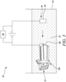
- FIG 3 illustrates an apparatus 50 for depositing the layer of nickel-based gamma/gamma prime chemistry 112 on the tip 106 of the aerofoil 100 of Figure 2 , according to an embodiment of the present disclosure.
- the apparatus 50 is an electroplating apparatus for depositing the layer of nickel-based gamma/gamma prime chemistry 112 on the tip 106.
- the apparatus 50 includes an electroplating cell 52, a cathode 54, an anode 56, and a voltage source 58.
- the electroplating cell 52 contains an electrolytic solution 55.
- the tip 106 of the aerofoil 100 which is to be coated is positioned in the electrolytic solution 55 within the electroplating cell 52 and electrically connected to the voltage source 58.
- the tip 106 of the aerofoil 100 serves as the cathode 54, or negatively charged electrode, of the electroplating cell 52, and is electrically connected to a negative pole of the voltage source 58.
- the voltage source 58 may be a source that delivers constant or varying voltage.
- the voltage source 58 is shown as a battery.
- the apparatus 50 further includes a plating material 59 placed in the electrolytic solution 55 and electrically connected to the voltage source 58.
- the plating material 59 serves as the anode 56, or positively charged electrode, of the electroplating cell 52, and is electrically connected to the positive pole of the voltage source 58.
- the plating material 59 includes the nickel-based gamma/gamma prime chemistry which is to be deposited on the tip 106 of the aerofoil 100.
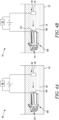
- FIG 4A illustrates an apparatus 60 for depositing a layer of nickel and/or cobalt on the tip 106 of the aerofoil 100 of Figure 2 , according to an embodiment of the present disclosure.
- the apparatus 60 is an electroplating apparatus for depositing the layer of nickel and/or cobalt on the tip 106.
- the layer to be deposited therefore includes nickel, cobalt, or any combinations thereof.
- the apparatus 60 includes an electroplating cell 62, a cathode 64, an anode 66, and a voltage source 68.
- the electroplating cell 62 contains an electrolytic solution 65.
- the tip 106 of the aerofoil 100 which is to be coated is positioned in the electrolytic solution 65 within the electroplating cell 62 and electrically connected to the voltage source 68.
- the tip 106 of the aerofoil 100 serves as the cathode 64, or negatively charged electrode, of the electroplating cell 62, and is electrically connected to a negative pole of the voltage source 68.
- the voltage source 68 may be a source that delivers constant or varying voltage.
- the voltage source 68 is shown as a battery.
- the apparatus 60 further includes a plating material 69 placed in the electrolytic solution 65 and electrically connected to the voltage source 68.
- the plating material 69 serves as the anode 66, or positively charged electrode, of the electroplating cell 62, and is electrically connected to the positive pole of the voltage source 68.
- the plating material 69 includes the nickel and/or cobalt which is to be deposited on the tip 106 of the aerofoil 100.
- the plating material therefore includes nickel, cobalt, or any combinations thereof.
- the plating material 69 is a suspended powder of the nickel and/or cobalt.
- Figure 4B illustrates an apparatus 70 for depositing a layer of chromium, aluminium, titanium, and/or tantalum on the layer of nickel and/or cobalt deposited by the apparatus 60 of Figure 4A , and thereby form the layer of nickel-based gamma/gamma prime chemistry 112 (shown in Figure 2 ), according to an embodiment of the present disclosure.
- the layer to be deposited therefore includes chromium, aluminium, titanium, tantalum, or any combinations thereof.
- the apparatus 70 is an electroplating apparatus for depositing the layer of chromium, aluminium, titanium, and/or tantalum on the layer of nickel and/or cobalt.
- the apparatus 70 includes an electroplating cell 72, a cathode 74, an anode 76, and a voltage source 78.
- the electroplating cell 72 contains an electrolytic solution 75.
- the tip 106 of the aerofoil 100 which is to be coated is positioned in the electrolytic solution 75 within the electroplating cell 72 and electrically connected to the voltage source 78.
- the tip 106 of the aerofoil 100 serves as the cathode 74, or negatively charged electrode, of the electroplating cell 72, and is electrically connected to a negative pole of the voltage source 78.
- the voltage source 78 may be a source that delivers constant or varying voltage.
- the voltage source 78 is shown as a battery.
- the apparatus 70 further includes a plating material 79 placed in the electrolytic solution 75 and electrically connected to the voltage source 78.
- the plating material 79 serves as the anode 76, or positively charged electrode, of the electroplating cell 72, and is electrically connected to the positive pole of the voltage source 78.
- the plating material 79 includes the chromium, aluminium, titanium, and/or tantalum which is to be deposited on the layer of nickel and/or cobalt.
- the plating material therefore includes chromium, aluminium, titanium, tantalum, or any combinations thereof.
- the plating material 79 is a suspended powder of the chromium, aluminium, titanium, and/or tantalum.
- Figure 5 illustrates an apparatus 80 for depositing the plurality of abrasive particles 114 on the layer of nickel-based gamma/gamma prime chemistry 112 deposited by the apparatus 50 of Figure 3 , and thereby form the coating matrix 116, according to an embodiment of the present disclosure.
- the apparatus 80 is an electroplating apparatus for depositing the plurality of abrasive particles 114 on the layer of nickel-based gamma/gamma prime chemistry 112.
- the apparatus 80 includes an electroplating cell 82, a cathode 84, an anode 86, and a voltage source 88.
- the electroplating cell 82 contains an electrolytic solution 85.
- the electrolytic solution 85 may include nickel sulfamate.
- the tip 106 of the aerofoil 100 which is to be coated is positioned in the electrolytic solution 85 within the electroplating cell 82 and electrically connected to the voltage source 88.
- the tip 106 of the aerofoil 100 serves as the cathode 84, or negatively charged electrode, of the electroplating cell 82, and is electrically connected to a negative pole of the voltage source 88.
- the voltage source 88 may be a source that delivers constant or varying voltage.
- the voltage source 88 is shown as a battery.
- the apparatus 80 further includes a plating material 89 placed in the electrolytic solution 85 and electrically connected to the voltage source 88.
- the plating material 89 serves as the anode 86, or positively charged electrode, of the electroplating cell 82, and is electrically connected to the positive pole of the voltage source 88.
- the plating material 89 includes the plurality of abrasive particles 114 which are to be deposited on the layer of nickel-based gamma/gamma prime chemistry 112.
- Figure 6 illustrates an apparatus 200 for depositing the layer of nickel-based gamma/gamma prime chemistry 112 on the tip of the aerofoil 100 of Figure 2 , and further depositing the plurality of abrasive particles 114 on the layer of nickel-based gamma/gamma prime chemistry 112, and thereby form the coating matrix 116, according to an embodiment of the present disclosure.
- the apparatus 200 includes a laser unit 202 configured to emit a laser beam 204 towards the tip 106 of the aerofoil 100.
- the laser unit 202 may be a solid-state laser.
- the solid-state laser may be neodymium:yttrium aluminium garnet (Nd:YAG) or Nd:glass.
- the apparatus 200 further includes a feeder 206 configured to feed powder of nickel-based gamma/gamma prime chemistry and the plurality of abrasive particles 114.
- the feeder 206 may include a nozzle.
- the apparatus 200 is configured to deposit the layer of nickel-based gamma/gamma prime chemistry 112 on the tip 106 by direct laser deposition through the laser beam 204.
- the feeder 206 feeds the powder of nickel-based gamma/gamma prime chemistry towards the tip 106.
- the apparatus 200 is further configured to deposit the plurality of abrasive particles 114 on the layer of nickel-based gamma/gamma prime chemistry 112 by direct laser deposition through the laser beam 204.
- the feeder 206 For depositing the plurality of abrasive particles 114 on the layer of nickel-based gamma/gamma prime chemistry 112 by direct laser deposition, the feeder 206 feeds the plurality of abrasive particles 114 towards the tip 106. The deposition of the plurality of abrasive particles 114 on the layer of nickel-based gamma/gamma prime chemistry 112 leads to formation of the coating matrix 116. In some embodiments, the feeder 206 may feed a mixture of the powder of nickel-based gamma/gamma prime chemistry and the plurality of abrasive particles 114.
- the apparatus 200 further includes a shielding unit 208 configured to emit a shielding gas 210 around the laser beam 204.
- the shielding unit 208 may include a nozzle to emit the shielding gas 210 around the laser beam 204.
- the shielding gas 210 may include at least one of nitrogen, helium, and argon.
- the shielding gas 210 is used to protect the material of the tip 106 from oxidation during laser deposition of the layer of nickel-based gamma/gamma prime chemistry 112 and the plurality of abrasive particles 114. In other words, the shielding gas 210 provides an inert atmosphere around the tip 106.
- FIG 7 illustrates an apparatus 300 for heat treatment of the coating matrix 116 formed by the apparatus 80 of Figure 5 and/or the apparatus 200 of Figure 6 and thereby form the high-strength coating 110 on the tip 106 of the aerofoil 100, according to an embodiment of the present disclosure.
- the apparatus 300 includes a laser unit 302 configured to emit a laser beam 304 towards the tip 106 of the aerofoil 100.
- the laser unit 302 may be a solid-state laser.
- the laser unit 302 may be the same as the laser unit 202 (shown in Figure 6 ).
- the laser unit 302 is configured to heat the tip 106 of the aerofoil 100 at a predetermined temperature and perform the heat treatment of the coating matrix 116.
- the predetermined temperature is between 1200 °C and 1300 °C. Heat treatment of the coating matrix 116 at such temperatures may increase the hot strength of the coating matrix 116 to greater than 10 MPa at operating temperatures of greater than 1000 °C.
- the apparatus 300 further includes a shielding unit 308 configured to emit a shielding gas 310 around the laser beam 304.
- the shielding unit 308 may be the same as the shielding unit 208 shown in Figure 6 .
- the shielding gas 310 is used to protect the material of the tip 106 from oxidation during heat treatment of the coating matrix 116. In other words, the shielding gas 310 provides the inert atmosphere around the tip 106. Once the coating matrix 116 is heat treated, the coating matrix 116 becomes the high-strength coating 110. In some cases, the heat treatment of the coating matrix 116 may be conducted in a vacuum.
- the aerofoil 100 includes an uncoated portion 101 that is separate from the tip 106.
- the aerofoil 100 includes internal holes 103 for air cooling of the uncoated portion 101 of the aerofoil 100 during the heating of the tip 106 via the laser beam 304.
- the cooling of the uncoated portion 101 of the aerofoil 100 maintains a temperature of the uncoated portion 101 below 800 °C. Therefore, a temperature of the parent material of the aerofoil 100 may be kept below 800 °C during the heat treatment of the coating matrix 116. As a result, properties of the material of the uncoated portion 101 may be kept unchanged during the heat treatment of the coating matrix 116.
- a cooling jacket may also be used around the uncoated portion 101 for cooling purposes.
- the apparatus 300 further includes a heat shield 306 to insulate the uncoated portion 101 of the aerofoil 100 from the tip 106 of the aerofoil 100 during the heating of the tip 106 at the predetermined temperature. Such an insulation may keep the temperature of the uncoated portion 101 of the aerofoil 100 below 800 °C and further speed up the heat treatment of the coating matrix 116.
- Figure 8 illustrates an apparatus 300' for heat treatment of the coating matrix 116 formed by the apparatus 80 of Figure 5 and/or the apparatus 200 of Figure 6 and thereby form the high-strength coating 110 on the tip 106 of the aerofoil 100, according to an embodiment of the present disclosure.
- the apparatus 300' is substantially similar to the apparatus 300 of Figure 7 , with common components being referred to by the same numerals. However, the apparatus 300' does not include a laser unit (i.e., the laser unit 302 shown in Figure 7 ). Instead, the apparatus 300' includes an induction heater 303 to heat the tip 106 and perform the heat treatment of the coating matrix 116.
- the induction heater 303 may be an induction coil.
- heat treatment of the coating matrix at the predetermined temperature may increase the hot strength of the coating matrix 116 to greater than 10 MPa at temperatures above 1000 °C.
- heating of the tip 106 of the aerofoil 100 at the predetermined temperature may form required microstructures which may be compatible with a single crystal base material of the aerofoil 100.
- the high-strength coating 110 may not suffer from creep.
- the high-strength coating 110 may be relatively less oxidised as compared to already known coatings consisting of cubic boron nitride (cBN) particles embedded in a refractory coating or MCrAlY.
- the ductile/brittle transition temperature of nickel-based gamma/gamma prime chemistry is relatively high.
- the relatively high ductile/brittle transition temperature of nickel-based gamma/gamma prime chemistry implies that the layer of nickel-based gamma/gamma prime chemistry 112 may have sufficient strength to retain the plurality of abrasive particles 114.
- heat treatment of the nickel-based gamma/gamma prime chemistry leads to formation of gamma/gamma prime super alloy structure with high strength.
- the coating matrix 116 may have sufficient strength to hold the abrasive particles 114 in place in the presence of shear loads imparted into the high-strength coating 110.
- induction heating is an efficient technique for localized heating of a component (i.e., the tip 106 of the aerofoil 100).
- the localized induction heating of the tip 106 may refine a structure of the coating matrix 116 such that it has desirable properties with which the high-strength coating 110 can withstand temperatures above 1000 °C.
- Figure 9 is an enlarged view of the tip 106 of the aerofoil 100 illustrating the high-strength coating 110 on the tip 106, according to an embodiment of the present disclosure. As shown in Figure 9 , at least some of the abrasive particles 114 are partially embedded within the layer of nickel-based gamma/gamma prime chemistry 112 and partially extend from the layer of nickel-based gamma/gamma prime chemistry 112.
- Figure 10 is a flowchart illustrating a method 400 for coating the tip 106 of the aerofoil 100 of Figure 2 , according to an embodiment of the present disclosure.
- the method 400 includes depositing the layer of nickel-based gamma/gamma prime chemistry 112 on the tip 106 of the aerofoil 100.
- depositing the layer of nickel-based gamma/gamma prime chemistry 112 on the tip 106 of the aerofoil 100 further includes depositing the layer of nickel-based gamma/gamma prime chemistry 112 on the tip 106 by electroplating.
- depositing the layer of nickel-based gamma/gamma prime chemistry 112 on the tip 106 of the aerofoil 100 further includes depositing the layer of nickel and/or cobalt on the tip 106 of the aerofoil 100.
- depositing the layer of nickel-based gamma/gamma prime chemistry 112 on the tip 106 of the aerofoil 100 further includes depositing the layer of chromium, aluminium, titanium, and/or tantalum on the layer of nickel and/or cobalt.
- depositing the layer of nickel-based gamma/gamma prime chemistry 112 on the tip 106 of the aerofoil 100 further includes depositing the layer of nickel-based gamma/gamma prime chemistry 112 on the tip 106 by direct laser deposition.
- the method 400 further includes depositing the plurality of abrasive particles 114 on the layer of nickel-based gamma/gamma prime chemistry 112 to form the coating matrix 116.
- depositing the plurality of abrasive particles 114 further includes depositing the plurality of abrasive particles 114 by electroplating.
- depositing the plurality of abrasive particles 114 on the layer of nickel-based gamma/gamma prime chemistry 112 further includes depositing the plurality of abrasive particles 114 by direct laser deposition.
- the method 400 further includes heating the tip 106 of the aerofoil 100 at the predetermined temperature in order to perform heat treatment of the coating matrix 116 and form the high-strength coating 110 on the tip 106 of the aerofoil 100.
- heating the tip 106 of the aerofoil 100 further includes laser heating of the tip 106.
- heating the tip 106 of the aerofoil 100 further includes induction heating of the tip 106.
- the method 400 further includes providing the vacuum or the inert atmosphere around the tip 106 during the heating of the tip 106 at the predetermined temperature.
- the method 400 further includes cooling the uncoated portion 101 of the aerofoil 100 during the heating of the tip 106 at the predetermined temperature.
- the cooling of the uncoated portion 101 of the aerofoil 100 maintains the temperature of the uncoated portion 101 below 800 °C.
- the method 400 further includes insulating, via the heat shield 306, the uncoated portion 101 of the aerofoil 100 from the tip 106 of the aerofoil 100 during the heating of the tip 106 at the predetermined temperature.
Landscapes
- Engineering & Computer Science (AREA)
- Chemical & Material Sciences (AREA)
- Materials Engineering (AREA)
- Metallurgy (AREA)
- Organic Chemistry (AREA)
- Mechanical Engineering (AREA)
- Chemical Kinetics & Catalysis (AREA)
- Electrochemistry (AREA)
- General Engineering & Computer Science (AREA)
- Inorganic Chemistry (AREA)
- Other Surface Treatments For Metallic Materials (AREA)
- Turbine Rotor Nozzle Sealing (AREA)
Abstract
A method (400) for coating a tip (106) of an aerofoil (100) is provided. The method (400) includes depositing a layer of nickel-based gamma/gamma prime chemistry (112) on the tip (106) of the aerofoil (100). The method (400) further includes depositing plurality of abrasive particles (114) on the layer of nickel-based gamma/gamma prime chemistry (112) to form a coating matrix (116). The method (400) further includes heating the tip (106) of the aerofoil (100) at a predetermined temperature in order to perform heat treatment of the coating matrix (116) and increase the strength of the coating (110) on the tip (106) of the aerofoil (100).
Description
- The present disclosure generally relates to an aerofoil, and in particular to a method for coating a tip of an aerofoil.
- Turbine blades in gas turbines are generally formed with tip shrouds in order to prevent leakage of air over the tips of the turbine blades. However, the necessity for cost reduction requires that blade numbers are reduced, which makes the use of shrouded blades impractical. This is due to the excessive circumferential length of the shroud. Shroudless blades can be run at higher rotational speeds due to their lower weights, but they tend to suffer from overtip leakage compromising performance. Overtip leakage can be minimised by coating the tips of shroudless blades with an abrasive material. Engine casing is also coated with an abradable lining. During operation of the gas turbine engine, the abrasive tip machines a track in the lining which results in good control of leakage around the tips of the turbine blades. Such blades are typically formed as single crystals of a metal alloy to withstand the elevated temperatures in the moving parts of the gas turbine engine.
- For a shroudless turbine blade, an abrasive tip coating generally consists of a ceramic grit, such as cubic boron nitride (cBN) particles or silicon carbide (SiC) particles, embedded in a matrix of refractory coating. The refractory coating is relatively ductile and has the disadvantage that it may suffer from creep. In addition, the ceramic grit may be oxidised. A further disadvantage is that the abrasive tip coating itself may be completely lost during the operation of the gas turbine engine.
- In some applications, the abrasive tip coating consists of an abrasive coating of the cBN particles held in a matrix of MCrAlY (where M is one or more of nickel, cobalt and iron, Cr is chromium, Al is aluminium, and Y is one or more of yttrium, ytterbium, lanthanum and other rare earth metals, or aluminide bond coatings) applied by composite electroplating. A ductile/brittle transition temperature of MCrAlY is relatively low. The relatively low ductile/brittle transition temperature of MCrAlY implies that high operating temperatures of the turbine blade tips coated in this way should be kept low so as to enable the MCrAlY matrix to have sufficient strength to retain the cBN particles. Therefore, upon occurrence of the high operating temperatures of the turbine blade tips, the MCrAlY matrix may have insufficient strength to retain the cBN particles. This may render the abrasive tip coating useless in shroudless turbine blades.
- In some applications, the abrasive tip coating consists of an abrasive coating of the cBN particles held in a matrix of gamma/gamma prime chemistry. However, such abrasive tip coating may have a hot strength of less than 10 MPa at temperatures above 1000 °C. As a result, such abrasive tip coating may have insufficient strength to hold the abrasive particles (cBN particles) in place due to shear loads imparted into the abrasive tip coating. Therefore, there exists a need for a method for improved coating of a tip of a shroudless turbine blade.
- As used herein, the term "nickel-based gamma/gamma prime chemistry" means either nickel-based gamma chemistry or nickel-based gamma prime chemistry.
- According to a first aspect there is provided a method for coating a tip of an aerofoil. The method includes depositing a layer of nickel-based gamma/gamma prime chemistry on the tip of the aerofoil. The method further includes depositing plurality of abrasive particles on the layer of nickel-based gamma/gamma prime chemistry to form a coating matrix. The method further includes heating the tip of the aerofoil at a predetermined temperature in order to perform heat treatment of the coating matrix and form a high-strength coating on the tip of the aerofoil.
- Heat treatment of the coating matrix at the predetermined temperature (greater than at least 1000 °C) may increase the hot strength to greater than 10 MPa at temperatures above 1000 °C. In other words, heating of the tip of the aerofoil at the predetermined temperature may form required microstructures which may be compatible with a single crystal base material of the aerofoil. The high-strength coating may not suffer from creep. In addition, the high-strength coating may be relatively less oxidised as compared to already known coatings consisting of cubic boron nitride (cBN) particles embedded in a refractory coating or MCrAlY.
- Due to heat treatment of the coating matrix, the ductile/brittle transition temperature of nickel-based gamma/gamma prime chemistry is relatively high. The relatively high ductile/brittle transition temperature of nickel-based gamma/gamma prime chemistry implies that the layer of nickel-based gamma/gamma prime chemistry may have sufficient strength to retain the plurality of abrasive particles. Moreover, heat treatment of the nickel-based gamma/gamma prime chemistry leads to formation of gamma/gamma prime super alloy structure with high strength. In other words, the coating matrix may have sufficient strength to hold the abrasive particles in place in the presence of shear loads imparted into the high-strength coating. As a result, when the aerofoil having the tip coated by the high-strength coating is used as a shroudless turbine blade in a gas turbine engine, overtip leakage may be minimised.
- In some embodiments, heating the tip of the aerofoil further includes induction heating of the tip. The induction heating of the tip may include heating by an induction coil. Induction heating is an efficient technique for localized heating of a component (i.e., the tip of the aerofoil). The localized induction heating of the tip may refine a structure of the coating matrix such that it has desirable properties with which the high-strength coating can withstand temperatures above 1000 °C.
- In some embodiments, heating the tip of the aerofoil further includes laser heating of the tip. Lasers are commonly used in industries where intense, localised heat treatment of a component is required. Thus, laser heating of the tip is another efficient technique for localized heating of a component (i.e., the tip of the aerofoil). A solid-state laser may be used for heating of the tip. The solid-state laser may be neodymium:yttrium aluminium garnet (Nd:YAG) or Nd:glass.
- In some embodiments, the method further includes cooling an uncoated portion of the aerofoil during the heating of the tip at the predetermined temperature. The cooling of the uncoated portion of the aerofoil maintains a temperature of the uncoated portion below 800 °C. Therefore, a temperature of a parent material of the aerofoil may be kept below 800 °C during the heat treatment of the coating matrix. As a result, properties of the material of the uncoated portion may be kept unchanged during the heat treatment of the coating matrix. In some cases, the cooling of the uncoated portion of the aerofoil may be done by air cooling through internal holes on the aerofoil.
- In some embodiments, the method further includes insulating, via a heat shield, the uncoated portion of the aerofoil from the tip of the aerofoil during the heating of the tip at the predetermined temperature. Such an insulation via the heat shield may keep the temperature of the uncoated portion of the aerofoil below 800 °C and further speed up the heat treatment of the coating matrix.
- In some embodiments, depositing the layer of nickel-based gamma/gamma prime chemistry on the tip of the aerofoil further includes depositing a layer of nickel and/or cobalt on the tip of the aerofoil. Depositing the layer of nickel-based gamma/gamma prime chemistry on the tip of the aerofoil further includes depositing a layer of chromium, aluminium, titanium, and/or tantalum on the layer of nickel and/or cobalt. The layer of nickel-based gamma/gamma prime chemistry may act as a thermal barrier coating on the tip of the aerofoil. Further, the layer of nickel-based gamma/gamma prime chemistry in the high-strength coating may increase a spallation resistance of the tip of the aerofoil.
- In some embodiments, depositing the layer of nickel-based gamma/gamma prime chemistry on the tip of the aerofoil includes depositing the layer of nickel-based gamma/gamma prime chemistry on the tip by electroplating. The deposition of the layer of nickel-based gamma/gamma prime chemistry by electroplating may improve a corrosion resistance of the tip of the aerofoil. The deposition of the layer of nickel-based gamma/gamma prime chemistry by electroplating may also improve adhesion between the parent material of the tip and the layer of nickel-based gamma/gamma prime chemistry.
- In some embodiments, depositing the plurality of abrasive particles further includes depositing the plurality of abrasive particles by electroplating. The deposition of the plurality of abrasive particles by electroplating may reduce wear and tear of the tip of the aerofoil and extend a lifetime of the aerofoil.
- The deposition of the plurality of abrasive particles by electroplating may also improve adhesion between the layer of nickel-based gamma/gamma prime chemistry and the plurality of abrasive particles.
- In some embodiments, depositing the layer of nickel-based gamma/gamma prime chemistry on the tip of the aerofoil further includes depositing the layer of nickel-based gamma/gamma prime chemistry by direct laser deposition. Depositing the plurality of abrasive particles on the layer of nickel-based gamma/gamma prime chemistry further includes depositing the plurality of abrasive particles by direct laser deposition. Deposition of the layer of nickel-based gamma/gamma prime chemistry on the tip of the aerofoil by direct laser deposition may involve low and controllable heat input to the tip and may also cause minimal distortion of the tip. Further, deposition of the plurality of abrasive particles on the layer of nickel-based gamma/gamma prime chemistry by direct laser deposition may involve low and controllable heat input to the layer of nickel-based gamma/gamma prime chemistry.
- In some embodiments, each of the plurality of abrasive particles includes cubic boron nitride (cBN). The cBN particles are well known abrasive particles specifically for advanced wear-resistant characteristics. Therefore, the presence of the cBN particles in high-strength coating may improve wear-resistant properties of the tip of the aerofoil.
- In some embodiments, the method further includes providing a vacuum or an inert atmosphere around the tip during the heating of the tip at the predetermined temperature. This may prevent oxidation of the material of the tip of the aerofoil during the heat treatment of the coating matrix.
- In some embodiments, the predetermined temperature is between 1200 °C and 1300 °C. Heat treatment of the coating matrix at such temperatures may increase the hot strength of the coating matrix to greater than 10 MPa at operating temperatures of greater than 1000 °C.
- In some embodiments, at least some of the abrasive particles are partially embedded within the layer of nickel-based gamma/gamma prime chemistry and partially extend from the layer of nickel-based gamma/gamma prime chemistry. This may enable the layer of nickel-based gamma/gamma prime chemistry to firmly hold the abrasive particles.
- According to a second aspect there is provided an aerofoil for a gas turbine engine. The aerofoil includes a body extending between a root and a tip. The aerofoil further includes a high-strength coating disposed on the tip. The high-strength coating includes a layer of nickel-based gamma/gamma prime super chemistry and a plurality of abrasive particles disposed on the layer of nickel-based gamma/gamma prime chemistry.
- Due to heat treatment of the coating matrix, the ductile/brittle transition temperature of nickel-based gamma/gamma prime chemistry is relatively high. The relatively high ductile/brittle transition temperature of nickel-based gamma/gamma prime chemistry implies that the nickel-based gamma/gamma prime chemistry may have sufficient strength to retain the plurality of abrasive particles during the operation of the gas turbine engine. Moreover, heat treatment of the nickel-based gamma/gamma prime chemistry leads to formation of gamma/gamma prime super alloy structure with high strength. As a result, when the aerofoil of the present disclosure is used as a shroudless turbine blade in the gas turbine engine, overtip leakage may be minimised.
- As noted elsewhere herein, the present disclosure may relate to a gas turbine engine. Such a gas turbine engine may comprise an engine core comprising a turbine, a combustor, a compressor, and a core shaft connecting the turbine to the compressor. Such a gas turbine engine may comprise a fan (having fan blades) located upstream of the engine core.
- Arrangements of the present disclosure may be particularly, although not exclusively, beneficial for fans that are driven via a gearbox. Accordingly, the gas turbine engine may comprise a gearbox that receives an input from the core shaft and outputs drive to the fan so as to drive the fan at a lower rotational speed than the core shaft. The input to the gearbox may be directly from the core shaft, or indirectly from the core shaft, for example via a spur shaft and/or gear. The core shaft may rigidly connect the turbine and the compressor, such that the turbine and compressor rotate at the same speed (with the fan rotating at a lower speed). The gearbox may be a reduction gearbox (in that the output to the fan is a lower rotational rate than the input from the core shaft). Any type of gearbox may be used.
- The gas turbine engine as described and/or claimed herein may have any suitable general architecture. For example, the gas turbine engine may have any desired number of shafts that connect turbines and compressors, for example one, two or three shafts. Purely by way of example, the turbine connected to the core shaft may be a first turbine, the compressor connected to the core shaft may be a first compressor, and the core shaft may be a first core shaft. The engine core may further comprise a second turbine, a second compressor, and a second core shaft connecting the second turbine to the second compressor. The second turbine, second compressor, and second core shaft may be arranged to rotate at a higher rotational speed than the first core shaft.
- In such an arrangement, the second compressor may be positioned axially downstream of the first compressor. The second compressor may be arranged to receive (for example directly receive, for example via a generally annular duct) flow from the first compressor.
- In any gas turbine engine as described and/or claimed herein, a combustor may be provided axially downstream of the fan and compressor(s). For example, the combustor may be directly downstream of (for example at the exit of) the second compressor, where a second compressor is provided. By way of further example, the flow at the exit to the combustor may be provided to the inlet of the second turbine, where a second turbine is provided. The combustor may be provided upstream of the turbine(s).
- The or each compressor (for example the first compressor and second compressor as described above) may comprise any number of stages, for example multiple stages. Each stage may comprise a row of rotor blades and a row of stator vanes, which may be variable stator vanes (in that their angle of incidence may be variable). The row of rotor blades and the row of stator vanes may be axially offset from each other.
- The or each turbine (for example the first turbine and second turbine as described above) may comprise any number of stages, for example multiple stages. Each stage may comprise a row of rotor blades and a row of stator vanes. The row of rotor blades and the row of stator vanes may be axially offset from each other.
- Gas turbine engines in accordance with the present disclosure may have any desired bypass ratio, where the bypass ratio is defined as the ratio of the mass flow rate of the flow through the bypass duct to the mass flow rate of the flow through the core at cruise conditions. The bypass duct may be substantially annular. The bypass duct may be radially outside the engine core. The radially outer surface of the bypass duct may be defined by a nacelle and/or a fan case.
- Specific thrust of an engine may be defined as the net thrust of the engine divided by the total mass flow through the engine. At cruise conditions, the specific thrust of an engine described and/or claimed herein may be less than (or on the order of) any of the following: 110 Nkg-1s, 105 Nkg-1s, 100 Nkg-1s, 95 Nkg-1s, 90 Nkg-1s, 85 Nkg-1s or 80 Nkg-1s. The specific thrust may be in an inclusive range bounded by any two of the values in the previous sentence (i.e. the values may form upper or lower bounds), for example in the range of from 80 Nkg-1s to 100 Nkg-1s, or 85 Nkg-1s to 95 Nkg-1s. Such engines may be particularly efficient in comparison with conventional gas turbine engines.
- A fan blade and/or aerofoil portion of a fan blade described and/or claimed herein may be manufactured from any suitable material or combination of materials. For example at least a part of the fan blade and/or aerofoil may be manufactured at least in part from a composite, for example a metal matrix composite and/or an organic matrix composite, such as carbon fibre.
- The fan of a gas turbine as described and/or claimed herein may have any desired number of fan blades, for example 14, 16, 18, 20, 22, 24 or 26 fan blades.
- The skilled person will appreciate that except where mutually exclusive, a feature or parameter described in relation to any one of the above aspects may be applied to any other aspect. Furthermore, except where mutually exclusive, any feature or parameter described herein may be applied to any aspect and/or combined with any other feature or parameter described herein.
- Embodiments will now be described by way of example only, with reference to the Figures, in which:
-
Figure 1 is a sectional side view of a gas turbine engine; -
Figure 2 is a perspective view of an aerofoil of the gas turbine engine ofFigure 1 , according to an embodiment of the present disclosure; -
Figure 3 illustrates an apparatus for depositing a layer of nickel-based gamma/gamma prime chemistry on a tip of the aerofoil ofFigure 2 , according to an embodiment of the present disclosure; -
Figure 4A illustrates an apparatus for depositing a layer of nickel and/or cobalt on a tip of the aerofoil ofFigure 2 , according to an embodiment of the present disclosure; -
Figure 4B illustrates an apparatus for depositing a layer of chromium, aluminium, titanium, and/or tantalum on the layer of nickel and/or cobalt deposited by the apparatus ofFigure 4A , and thereby form the layer of nickel-based gamma/gamma prime chemistry, according to an embodiment of the present disclosure; -
Figure 5 illustrates an apparatus for depositing a plurality of abrasive particles on the layer of nickel-based gamma/gamma prime chemistry deposited by the apparatus ofFigure 3 , and thereby form a coating matrix, according to an embodiment of the present disclosure; -
Figure 6 illustrates an apparatus for depositing a layer of nickel-based gamma/gamma prime chemistry on a tip of the aerofoil ofFigure 2 , and further depositing a plurality of abrasive particles on the layer of nickel-based gamma/gamma prime chemistry, and thereby form a coating matrix, according to an embodiment of the present disclosure; -
Figure 7 illustrates an apparatus for heat treatment of the coating matrix formed by the apparatus ofFigure 5 and/or the apparatus ofFigure 6 , and thereby form a high-strength coating on a tip of the aerofoil ofFigure 2 , according to an embodiment of the present disclosure; -
Figure 8 illustrates an apparatus for heat treatment of the coating matrix formed by the apparatus ofFigure 5 and/or the apparatus ofFigure 6 , and thereby form a high-strength coating on a tip of the aerofoil ofFigure 2 , according to another embodiment of the present disclosure; -
Figure 9 is an enlarged view of the tip of the aerofoil illustrating the high-strength coating on the tip, according to an embodiment of the present disclosure; and -
Figure 10 is a flowchart illustrating a method for coating a tip of the aerofoil ofFigure 2 , according to an embodiment of the present disclosure. - Aspects and embodiments of the present disclosure will now be discussed with reference to the accompanying figures. Further aspects and embodiments will be apparent to those skilled in the art.
- As used herein, the term "nickel-based gamma/gamma prime chemistry" means either nickel-based gamma chemistry or nickel-based gamma prime chemistry.
-
Figure 1 illustrates agas turbine engine 10 having a principalrotational axis 9. Theengine 10 comprises anair intake 12 and apropulsive fan 23 that generates two airflows: a core airflow A and a bypass airflow B. Thegas turbine engine 10 comprises a core 11 that receives the core airflow A. Theengine core 11 comprises, in axial flow series, alow pressure compressor 14, ahigh pressure compressor 15,combustion equipment 16, ahigh pressure turbine 17, alow pressure turbine 19, and acore exhaust nozzle 20. Anacelle 21 surrounds thegas turbine engine 10 and defines abypass duct 22 and abypass exhaust nozzle 18. The bypass airflow B flows through thebypass duct 22. Thefan 23 is attached to and driven by thelow pressure turbine 19 via ashaft 26 and anepicyclic gearbox 30. - In use, the core airflow A is accelerated and compressed by the
low pressure compressor 14 and directed into thehigh pressure compressor 15 where further compression takes place. The compressed air exhausted from thehigh pressure compressor 15 is directed into thecombustion equipment 16 where it is mixed with fuel and the mixture is combusted. The resultant hot combustion products then expand through, and thereby drive, the high pressure andlow pressure turbines core exhaust nozzle 20 to provide some propulsive thrust. Thehigh pressure turbine 17 drives thehigh pressure compressor 15 by a suitable interconnectingshaft 27. Thefan 23 generally provides the majority of the propulsive thrust. Theepicyclic gearbox 30 is a reduction gearbox.
Note that the terms "low pressure turbine" and "low pressure compressor" as used herein may be taken to mean the lowest pressure turbine stages and lowest pressure compressor stages (i.e. not including the fan 23) respectively and/or the turbine and compressor stages that are connected together by the interconnectingshaft 26 with the lowest rotational speed in the engine (i.e. not including the gearbox output shaft that drives the fan 23). In some literature, the "low pressure turbine" and "low pressure compressor" referred to herein may alternatively be known as the "intermediate pressure turbine" and "intermediate pressure compressor". Where such alternative nomenclature is used, thefan 23 may be referred to as a first, or lowest pressure, compression stage. - Other gas turbine engines to which the present disclosure may be applied may have alternative configurations. For example, such engines may have an alternative number of compressors and/or turbines and/or an alternative number of interconnecting shafts. By way of further example, the gas turbine engine shown in
Figure 1 has asplit flow nozzle bypass duct 22 has itsown nozzle 18 that is separate to and radially outside thecore exhaust nozzle 20. However, this is not limiting, and any aspect of the present disclosure may also apply to engines in which the flow through thebypass duct 22 and the flow through the core 11 are mixed, or combined, before (or upstream of) a single nozzle, which may be referred to as a mixed flow nozzle. One or both nozzles (whether mixed or split flow) may have a fixed or variable area. - The geometry of the
gas turbine engine 10, and components thereof, is defined by a conventional axis system, comprising an axial direction (which is aligned with the rotational axis 9), a radial direction (in the bottom-to-top direction inFigure 1 ), and a circumferential direction (perpendicular to the page in theFigure 1 view). The axial, radial and circumferential directions are mutually perpendicular. -
Figure 2 is a perspective view of anaerofoil 100 of thegas turbine engine 10 ofFigure 1 , according to an embodiment of the present disclosure. In some embodiments, theaerofoil 100 is a turbine blade. In some embodiments, theaerofoil 100 is a turbine blade of the high pressure turbine 17 (shown inFigure 1 ). In some embodiments, theaerofoil 100 is a turbine blade of thelow pressure turbine 19. In the illustrated embodiment ofFigure 2 , theaerofoil 100 is a shroudless turbine blade. - The
aerofoil 100 includes abody 102 extending between aroot 104 and atip 106. Theaerofoil 100 is mounted on a disk (not shown) for rotation at operating speeds. Theroot 104 is attached to the disk. Theaerofoil 100 further includes aplatform 108 connecting theroot 104 and thebody 102. - The
aerofoil 100 further includes a high-strength coating 110 disposed on thetip 106. The high-strength coating 110 includes a layer of nickel-based gamma/gammaprime chemistry 112 and a plurality ofabrasive particles 114 disposed on the layer of nickel-based gamma/gammaprime chemistry 112. The plurality ofabrasive particles 114 and the layer of nickel-based gamma/gammaprime chemistry 112 together form acoating matrix 116. Thecoating matrix 116 is further heat treated to form the high-strength coating 110 on thetip 106 of theaerofoil 100. - In some embodiments, each of the plurality of
abrasive particles 114 includes cubic boron nitride (cBN). The cBN particles are well known for advanced wear-resistant characteristics. Therefore, the presence of the cBN particles in the high-strength coating 110 may improve wear-resistant properties of thetip 106 of theaerofoil 100. In some embodiments, the plurality ofabrasive particles 114 may include silicon carbide. - The nickel-based gamma chemistry is a continuous matrix having a face-centered-cubic (fcc) nickel-based austenitic phase that usually contains a high percentage of solid-solution elements, such as cobalt (Co), chromium (Cr), molybdenum (Mo), and Tungsten (W). The nickel-based gamma prime chemistry refers to a primary strengthening phase in nickel-based superalloys, i.e., Ni3(Al,Ti), where Ni stands for Nickel, Al stands for Aluminium, and Ti stands for titanium. It is a coherently precipitating phase (i.e., the crystal planes of the precipitate are in registry with the gamma matrix) with an ordered fcc crystal structure.
-
Figure 3 illustrates anapparatus 50 for depositing the layer of nickel-based gamma/gammaprime chemistry 112 on thetip 106 of theaerofoil 100 ofFigure 2 , according to an embodiment of the present disclosure. Theapparatus 50 is an electroplating apparatus for depositing the layer of nickel-based gamma/gammaprime chemistry 112 on thetip 106. Theapparatus 50 includes anelectroplating cell 52, acathode 54, ananode 56, and avoltage source 58. Theelectroplating cell 52 contains anelectrolytic solution 55. Thetip 106 of theaerofoil 100 which is to be coated is positioned in theelectrolytic solution 55 within theelectroplating cell 52 and electrically connected to thevoltage source 58. Thetip 106 of theaerofoil 100 serves as thecathode 54, or negatively charged electrode, of theelectroplating cell 52, and is electrically connected to a negative pole of thevoltage source 58. Thevoltage source 58 may be a source that delivers constant or varying voltage. Thevoltage source 58 is shown as a battery. - The
apparatus 50 further includes aplating material 59 placed in theelectrolytic solution 55 and electrically connected to thevoltage source 58. The platingmaterial 59 serves as theanode 56, or positively charged electrode, of theelectroplating cell 52, and is electrically connected to the positive pole of thevoltage source 58. The platingmaterial 59 includes the nickel-based gamma/gamma prime chemistry which is to be deposited on thetip 106 of theaerofoil 100. -
Figure 4A illustrates anapparatus 60 for depositing a layer of nickel and/or cobalt on thetip 106 of theaerofoil 100 ofFigure 2 , according to an embodiment of the present disclosure. Theapparatus 60 is an electroplating apparatus for depositing the layer of nickel and/or cobalt on thetip 106. The layer to be deposited therefore includes nickel, cobalt, or any combinations thereof. Theapparatus 60 includes anelectroplating cell 62, acathode 64, ananode 66, and avoltage source 68. Theelectroplating cell 62 contains anelectrolytic solution 65. Thetip 106 of theaerofoil 100 which is to be coated is positioned in theelectrolytic solution 65 within theelectroplating cell 62 and electrically connected to thevoltage source 68. Thetip 106 of theaerofoil 100 serves as thecathode 64, or negatively charged electrode, of theelectroplating cell 62, and is electrically connected to a negative pole of thevoltage source 68. Thevoltage source 68 may be a source that delivers constant or varying voltage. Thevoltage source 68 is shown as a battery. - The
apparatus 60 further includes a plating material 69 placed in theelectrolytic solution 65 and electrically connected to thevoltage source 68. The plating material 69 serves as theanode 66, or positively charged electrode, of theelectroplating cell 62, and is electrically connected to the positive pole of thevoltage source 68. The plating material 69 includes the nickel and/or cobalt which is to be deposited on thetip 106 of theaerofoil 100. The plating material therefore includes nickel, cobalt, or any combinations thereof. In some embodiments, the plating material 69 is a suspended powder of the nickel and/or cobalt. -
Figure 4B illustrates anapparatus 70 for depositing a layer of chromium, aluminium, titanium, and/or tantalum on the layer of nickel and/or cobalt deposited by theapparatus 60 ofFigure 4A , and thereby form the layer of nickel-based gamma/gamma prime chemistry 112 (shown inFigure 2 ), according to an embodiment of the present disclosure. The layer to be deposited therefore includes chromium, aluminium, titanium, tantalum, or any combinations thereof. Theapparatus 70 is an electroplating apparatus for depositing the layer of chromium, aluminium, titanium, and/or tantalum on the layer of nickel and/or cobalt. Theapparatus 70 includes anelectroplating cell 72, acathode 74, ananode 76, and avoltage source 78. Theelectroplating cell 72 contains anelectrolytic solution 75. Thetip 106 of theaerofoil 100 which is to be coated is positioned in theelectrolytic solution 75 within theelectroplating cell 72 and electrically connected to thevoltage source 78. Thetip 106 of theaerofoil 100 serves as thecathode 74, or negatively charged electrode, of theelectroplating cell 72, and is electrically connected to a negative pole of thevoltage source 78. Thevoltage source 78 may be a source that delivers constant or varying voltage. Thevoltage source 78 is shown as a battery. - The
apparatus 70 further includes a plating material 79 placed in theelectrolytic solution 75 and electrically connected to thevoltage source 78. The plating material 79 serves as theanode 76, or positively charged electrode, of theelectroplating cell 72, and is electrically connected to the positive pole of thevoltage source 78. The plating material 79 includes the chromium, aluminium, titanium, and/or tantalum which is to be deposited on the layer of nickel and/or cobalt. The plating material therefore includes chromium, aluminium, titanium, tantalum, or any combinations thereof. In some embodiments, the plating material 79 is a suspended powder of the chromium, aluminium, titanium, and/or tantalum. -
Figure 5 illustrates anapparatus 80 for depositing the plurality ofabrasive particles 114 on the layer of nickel-based gamma/gammaprime chemistry 112 deposited by theapparatus 50 ofFigure 3 , and thereby form thecoating matrix 116, according to an embodiment of the present disclosure. Theapparatus 80 is an electroplating apparatus for depositing the plurality ofabrasive particles 114 on the layer of nickel-based gamma/gammaprime chemistry 112. Theapparatus 80 includes anelectroplating cell 82, acathode 84, ananode 86, and avoltage source 88. Theelectroplating cell 82 contains anelectrolytic solution 85. Theelectrolytic solution 85 may include nickel sulfamate. Thetip 106 of theaerofoil 100 which is to be coated is positioned in theelectrolytic solution 85 within theelectroplating cell 82 and electrically connected to thevoltage source 88. Thetip 106 of theaerofoil 100 serves as thecathode 84, or negatively charged electrode, of theelectroplating cell 82, and is electrically connected to a negative pole of thevoltage source 88. Thevoltage source 88 may be a source that delivers constant or varying voltage. Thevoltage source 88 is shown as a battery. - The
apparatus 80 further includes aplating material 89 placed in theelectrolytic solution 85 and electrically connected to thevoltage source 88. The platingmaterial 89 serves as theanode 86, or positively charged electrode, of theelectroplating cell 82, and is electrically connected to the positive pole of thevoltage source 88. The platingmaterial 89 includes the plurality ofabrasive particles 114 which are to be deposited on the layer of nickel-based gamma/gammaprime chemistry 112. -
Figure 6 illustrates anapparatus 200 for depositing the layer of nickel-based gamma/gammaprime chemistry 112 on the tip of theaerofoil 100 ofFigure 2 , and further depositing the plurality ofabrasive particles 114 on the layer of nickel-based gamma/gammaprime chemistry 112, and thereby form thecoating matrix 116, according to an embodiment of the present disclosure. Theapparatus 200 includes alaser unit 202 configured to emit alaser beam 204 towards thetip 106 of theaerofoil 100. Thelaser unit 202 may be a solid-state laser. The solid-state laser may be neodymium:yttrium aluminium garnet (Nd:YAG) or Nd:glass. Theapparatus 200 further includes afeeder 206 configured to feed powder of nickel-based gamma/gamma prime chemistry and the plurality ofabrasive particles 114. Thefeeder 206 may include a nozzle. - The
apparatus 200 is configured to deposit the layer of nickel-based gamma/gammaprime chemistry 112 on thetip 106 by direct laser deposition through thelaser beam 204. For depositing the layer of nickel-based gamma/gammaprime chemistry 112 on thetip 106 by direct laser deposition, thefeeder 206 feeds the powder of nickel-based gamma/gamma prime chemistry towards thetip 106. Theapparatus 200 is further configured to deposit the plurality ofabrasive particles 114 on the layer of nickel-based gamma/gammaprime chemistry 112 by direct laser deposition through thelaser beam 204. For depositing the plurality ofabrasive particles 114 on the layer of nickel-based gamma/gammaprime chemistry 112 by direct laser deposition, thefeeder 206 feeds the plurality ofabrasive particles 114 towards thetip 106. The deposition of the plurality ofabrasive particles 114 on the layer of nickel-based gamma/gammaprime chemistry 112 leads to formation of thecoating matrix 116. In some embodiments, thefeeder 206 may feed a mixture of the powder of nickel-based gamma/gamma prime chemistry and the plurality ofabrasive particles 114. - The
apparatus 200 further includes ashielding unit 208 configured to emit a shieldinggas 210 around thelaser beam 204. Theshielding unit 208 may include a nozzle to emit the shieldinggas 210 around thelaser beam 204. In an example, the shieldinggas 210 may include at least one of nitrogen, helium, and argon. The shieldinggas 210 is used to protect the material of thetip 106 from oxidation during laser deposition of the layer of nickel-based gamma/gammaprime chemistry 112 and the plurality ofabrasive particles 114. In other words, the shieldinggas 210 provides an inert atmosphere around thetip 106. -
Figure 7 illustrates anapparatus 300 for heat treatment of thecoating matrix 116 formed by theapparatus 80 ofFigure 5 and/or theapparatus 200 ofFigure 6 and thereby form the high-strength coating 110 on thetip 106 of theaerofoil 100, according to an embodiment of the present disclosure. Theapparatus 300 includes alaser unit 302 configured to emit alaser beam 304 towards thetip 106 of theaerofoil 100. Thelaser unit 302 may be a solid-state laser. Thelaser unit 302 may be the same as the laser unit 202 (shown inFigure 6 ). Thelaser unit 302 is configured to heat thetip 106 of theaerofoil 100 at a predetermined temperature and perform the heat treatment of thecoating matrix 116. In some embodiments, the predetermined temperature is between 1200 °C and 1300 °C. Heat treatment of thecoating matrix 116 at such temperatures may increase the hot strength of thecoating matrix 116 to greater than 10 MPa at operating temperatures of greater than 1000 °C. - The
apparatus 300 further includes ashielding unit 308 configured to emit a shieldinggas 310 around thelaser beam 304. Theshielding unit 308 may be the same as theshielding unit 208 shown inFigure 6 . The shieldinggas 310 is used to protect the material of thetip 106 from oxidation during heat treatment of thecoating matrix 116. In other words, the shieldinggas 310 provides the inert atmosphere around thetip 106. Once thecoating matrix 116 is heat treated, thecoating matrix 116 becomes the high-strength coating 110. In some cases, the heat treatment of thecoating matrix 116 may be conducted in a vacuum. - The
aerofoil 100 includes anuncoated portion 101 that is separate from thetip 106. In some embodiments, theaerofoil 100 includesinternal holes 103 for air cooling of theuncoated portion 101 of theaerofoil 100 during the heating of thetip 106 via thelaser beam 304. The cooling of theuncoated portion 101 of theaerofoil 100 maintains a temperature of theuncoated portion 101 below 800 °C. Therefore, a temperature of the parent material of theaerofoil 100 may be kept below 800 °C during the heat treatment of thecoating matrix 116. As a result, properties of the material of theuncoated portion 101 may be kept unchanged during the heat treatment of thecoating matrix 116. In some cases, a cooling jacket may also be used around theuncoated portion 101 for cooling purposes. - The
apparatus 300 further includes aheat shield 306 to insulate theuncoated portion 101 of theaerofoil 100 from thetip 106 of theaerofoil 100 during the heating of thetip 106 at the predetermined temperature. Such an insulation may keep the temperature of theuncoated portion 101 of theaerofoil 100 below 800 °C and further speed up the heat treatment of thecoating matrix 116. -
Figure 8 illustrates anapparatus 300' for heat treatment of thecoating matrix 116 formed by theapparatus 80 ofFigure 5 and/or theapparatus 200 ofFigure 6 and thereby form the high-strength coating 110 on thetip 106 of theaerofoil 100, according to an embodiment of the present disclosure. Theapparatus 300' is substantially similar to theapparatus 300 ofFigure 7 , with common components being referred to by the same numerals. However, theapparatus 300' does not include a laser unit (i.e., thelaser unit 302 shown inFigure 7 ). Instead, theapparatus 300' includes aninduction heater 303 to heat thetip 106 and perform the heat treatment of thecoating matrix 116. Theinduction heater 303 may be an induction coil. - Referring to
Figures 7 and8 , heat treatment of the coating matrix at the predetermined temperature (greater than at least 1000 °C) may increase the hot strength of thecoating matrix 116 to greater than 10 MPa at temperatures above 1000 °C. In other words, heating of thetip 106 of theaerofoil 100 at the predetermined temperature may form required microstructures which may be compatible with a single crystal base material of theaerofoil 100. The high-strength coating 110 may not suffer from creep. In addition, the high-strength coating 110 may be relatively less oxidised as compared to already known coatings consisting of cubic boron nitride (cBN) particles embedded in a refractory coating or MCrAlY. - Due to heat treatment of the
coating matrix 116, the ductile/brittle transition temperature of nickel-based gamma/gamma prime chemistry is relatively high. The relatively high ductile/brittle transition temperature of nickel-based gamma/gamma prime chemistry implies that the layer of nickel-based gamma/gammaprime chemistry 112 may have sufficient strength to retain the plurality ofabrasive particles 114. Moreover, heat treatment of the nickel-based gamma/gamma prime chemistry leads to formation of gamma/gamma prime super alloy structure with high strength. In other words, thecoating matrix 116 may have sufficient strength to hold theabrasive particles 114 in place in the presence of shear loads imparted into the high-strength coating 110. As a result, when theaerofoil 100 having thetip 106 coated by the high-strength coating 110 is used as a shroudless turbine blade in the gas turbine engine 10 (shown inFigure 1 ), overtip leakage may be minimised. - Moreover, induction heating is an efficient technique for localized heating of a component (i.e., the
tip 106 of the aerofoil 100). The localized induction heating of thetip 106 may refine a structure of thecoating matrix 116 such that it has desirable properties with which the high-strength coating 110 can withstand temperatures above 1000 °C. -
Figure 9 is an enlarged view of thetip 106 of theaerofoil 100 illustrating the high-strength coating 110 on thetip 106, according to an embodiment of the present disclosure. As shown inFigure 9 , at least some of theabrasive particles 114 are partially embedded within the layer of nickel-based gamma/gammaprime chemistry 112 and partially extend from the layer of nickel-based gamma/gammaprime chemistry 112. -
Figure 10 is a flowchart illustrating amethod 400 for coating thetip 106 of theaerofoil 100 ofFigure 2 , according to an embodiment of the present disclosure. Referring toFigures 2 to 10 , atstep 402, themethod 400 includes depositing the layer of nickel-based gamma/gammaprime chemistry 112 on thetip 106 of theaerofoil 100. Referring toFigures 3 and10 , depositing the layer of nickel-based gamma/gammaprime chemistry 112 on thetip 106 of theaerofoil 100 further includes depositing the layer of nickel-based gamma/gammaprime chemistry 112 on thetip 106 by electroplating. Referring toFigures 4A and10 , depositing the layer of nickel-based gamma/gammaprime chemistry 112 on thetip 106 of theaerofoil 100 further includes depositing the layer of nickel and/or cobalt on thetip 106 of theaerofoil 100. Referring toFigures 4B and10 , depositing the layer of nickel-based gamma/gammaprime chemistry 112 on thetip 106 of theaerofoil 100 further includes depositing the layer of chromium, aluminium, titanium, and/or tantalum on the layer of nickel and/or cobalt. Referring toFigures 6 and10 , depositing the layer of nickel-based gamma/gammaprime chemistry 112 on thetip 106 of theaerofoil 100 further includes depositing the layer of nickel-based gamma/gammaprime chemistry 112 on thetip 106 by direct laser deposition. - Referring to
Figures 2 to 10 , atstep 404, themethod 400 further includes depositing the plurality ofabrasive particles 114 on the layer of nickel-based gamma/gammaprime chemistry 112 to form thecoating matrix 116. Referring toFigures 5 and10 , depositing the plurality ofabrasive particles 114 further includes depositing the plurality ofabrasive particles 114 by electroplating. Referring toFigures 6 and10 , depositing the plurality ofabrasive particles 114 on the layer of nickel-based gamma/gammaprime chemistry 112 further includes depositing the plurality ofabrasive particles 114 by direct laser deposition. - Referring to
Figures 2 ,7 ,8 , and10 , atstep 406, themethod 400 further includes heating thetip 106 of theaerofoil 100 at the predetermined temperature in order to perform heat treatment of thecoating matrix 116 and form the high-strength coating 110 on thetip 106 of theaerofoil 100. Referring toFigures 7 and10 , heating thetip 106 of theaerofoil 100 further includes laser heating of thetip 106. Referring toFigures 8 and10 , heating thetip 106 of theaerofoil 100 further includes induction heating of thetip 106. Referring again toFigures 2 ,7 ,8 , and10 , themethod 400 further includes providing the vacuum or the inert atmosphere around thetip 106 during the heating of thetip 106 at the predetermined temperature. Themethod 400 further includes cooling theuncoated portion 101 of theaerofoil 100 during the heating of thetip 106 at the predetermined temperature. The cooling of theuncoated portion 101 of theaerofoil 100 maintains the temperature of theuncoated portion 101 below 800 °C. Themethod 400 further includes insulating, via theheat shield 306, theuncoated portion 101 of theaerofoil 100 from thetip 106 of theaerofoil 100 during the heating of thetip 106 at the predetermined temperature. - It will be understood that the invention is not limited to the embodiments above-described and various modifications and improvements can be made without departing from the concepts described herein. Except where mutually exclusive, any of the features may be employed separately or in combination with any other features and the disclosure extends to and includes all combinations and sub-combinations of one or more features described herein.
Claims (15)
- A method (400) for coating a tip (106) of an aerofoil (100) for a gas turbine engine, the method (400) comprising:depositing a layer of nickel-based gamma/gamma prime chemistry (112) on the tip (106) of the aerofoil (100);depositing plurality of abrasive particles (114) on the layer of nickel-based gamma/gamma prime chemistry (112) to form a coating matrix (116); andheating the tip (106) of the aerofoil (100) at a predetermined temperature in order to perform heat treatment of the coating matrix (116) and increase the strength of the coating (110) on the tip (106) of the aerofoil (100).
- The method (400) of claim 1, wherein heating the tip (106) of the aerofoil (100) further comprises induction heating of the tip (106).
- The method (400) of claim 1, wherein heating the tip (106) of the aerofoil (100) further comprises laser heating of the tip (106).
- The method (400) of any one of the preceding claims, further comprising cooling an uncoated portion (101) of the aerofoil (100) during the heating of the tip (106) at the predetermined temperature, wherein the cooling of the uncoated portion (101) of the aerofoil (100) maintains a temperature of the uncoated portion (101) below 800 °C.
- The method (400) of claim 4, further comprising insulating, via a heat shield (306), the uncoated portion (101) of the aerofoil (100) from the tip (106) of the aerofoil (100) during the heating of the tip (106) at the predetermined temperature.
- The method (400) of any one of the preceding claims, wherein depositing the layer of nickel-based gamma/gamma prime chemistry (112) on the tip (106) of the aerofoil (100) further comprises:depositing a layer of nickel and/or cobalt on the tip (106) of the aerofoil (100); anddepositing a layer of chromium, aluminium, titanium, and/or tantalum on the layer of nickel and/or cobalt.
- The method (400) of claim 1, wherein depositing the layer of nickel-based gamma/gamma prime chemistry (112) on the tip (106) of the aerofoil (100) comprises depositing the layer of nickel-based gamma/gamma prime chemistry (112) on the tip (106) by electroplating.
- The method (400) of claim 1, wherein depositing the plurality of abrasive particles (114) further comprises depositing the plurality of abrasive particles (114) by electroplating.
- The method (400) of claim 1, wherein:depositing the layer of nickel-based gamma/gamma prime chemistry (112) on the tip (106) of the aerofoil (100) further comprises depositing the layer of nickel-based gamma/gamma prime chemistry (112) by direct laser deposition; anddepositing the plurality of abrasive particles (114) on the layer of nickel-based gamma/gamma prime chemistry (112) further comprises depositing the plurality of abrasive particles (114) by direct laser deposition.
- The method (400) of any one of the preceding claims, wherein each of the plurality of abrasive particles (114) comprises cubic boron nitride.
- The method (400) of any one of the preceding claims, further comprising providing a vacuum or an inert atmosphere around the tip (106) during the heating of the tip (106) at the predetermined temperature.
- The method (400) of any one of the preceding claims, wherein the predetermined temperature is between 1200 °C and 1300 °C.
- The method (400) of any one of the preceding claims, wherein at least some of the abrasive particles (114) are partially embedded within the layer of nickel-based gamma/gamma prime chemistry (112) and partially extend from the layer of nickel-based gamma/gamma prime chemistry (112).
- An aerofoil (100) for a gas turbine engine (10), the aerofoil (100) comprising:a body (102) extending between a root (104) and a tip (106); anda coating (110) disposed on the tip (106), the coating (110) comprising a layer of nickel-based gamma/gamma prime chemistry (112) and a plurality of abrasive particles (114) disposed on the layer of nickel-based gamma/gamma prime chemistry (112), the strength of the coating (110) being increased by heating the tip (106) of the aerofoil (100) at a predetermined temperature in order to perform heat treatment of the coating matrix (116).
- The aerofoil (100) of claim 14, wherein the aerofoil (100) is a turbine blade.
Applications Claiming Priority (1)
| Application Number | Priority Date | Filing Date | Title |
|---|---|---|---|
| GBGB2213705.3A GB202213705D0 (en) | 2022-09-20 | 2022-09-20 | Method for coating a tip of an aerofoil and aerofoil |
Publications (1)
| Publication Number | Publication Date |
|---|---|
| EP4343117A1 true EP4343117A1 (en) | 2024-03-27 |
Family
ID=84817691
Family Applications (1)
| Application Number | Title | Priority Date | Filing Date |
|---|---|---|---|
| EP23195970.1A Withdrawn EP4343117A1 (en) | 2022-09-20 | 2023-09-07 | Method for coating a tip of an aerofoil of a gas turbine engine |
Country Status (3)
| Country | Link |
|---|---|
| US (1) | US20240093613A1 (en) |
| EP (1) | EP4343117A1 (en) |
| GB (1) | GB202213705D0 (en) |
Citations (5)
| Publication number | Priority date | Publication date | Assignee | Title |
|---|---|---|---|---|
| US4818833A (en) * | 1987-12-21 | 1989-04-04 | United Technologies Corporation | Apparatus for radiantly heating blade tips |
| EP0573928A1 (en) * | 1992-06-08 | 1993-12-15 | Quantum Laser Corporation | Laser method for applying a matrix metal and pretreated clad abrasive particles to the tip of a turbine blade |
| GB2449862A (en) * | 2007-06-05 | 2008-12-10 | Rolls Royce Plc | Method of producing abrasive tips for gas turbine blades. |
| US20100266772A1 (en) * | 2009-04-20 | 2010-10-21 | Honeywell International Inc. | Methods of forming coating systems on superalloy turbine airfoils |
| US20160237581A1 (en) * | 2014-08-27 | 2016-08-18 | John Foster | Electroplated coatings |
Family Cites Families (5)
| Publication number | Priority date | Publication date | Assignee | Title |
|---|---|---|---|---|
| US4227703A (en) * | 1978-11-27 | 1980-10-14 | General Electric Company | Gas seal with tip of abrasive particles |
| JP2002256808A (en) * | 2001-02-28 | 2002-09-11 | Mitsubishi Heavy Ind Ltd | Combustion engine, gas turbine and grinding layer |
| US7896986B2 (en) * | 2004-09-02 | 2011-03-01 | Siemens Energy, Inc. | Heat treatment of superalloy components |
| GB2462704B (en) * | 2008-08-22 | 2010-07-21 | Rolls Royce Plc | A single crystal component and a method of heat treating a single crystal component |
| US20210260701A1 (en) * | 2020-02-21 | 2021-08-26 | Rolls-Royce Corporation | Additive manufacturing with rotatable deposition head |
-
2022
- 2022-09-20 GB GBGB2213705.3A patent/GB202213705D0/en not_active Ceased
-
2023
- 2023-09-06 US US18/242,816 patent/US20240093613A1/en not_active Abandoned
- 2023-09-07 EP EP23195970.1A patent/EP4343117A1/en not_active Withdrawn
Patent Citations (5)
| Publication number | Priority date | Publication date | Assignee | Title |
|---|---|---|---|---|
| US4818833A (en) * | 1987-12-21 | 1989-04-04 | United Technologies Corporation | Apparatus for radiantly heating blade tips |
| EP0573928A1 (en) * | 1992-06-08 | 1993-12-15 | Quantum Laser Corporation | Laser method for applying a matrix metal and pretreated clad abrasive particles to the tip of a turbine blade |
| GB2449862A (en) * | 2007-06-05 | 2008-12-10 | Rolls Royce Plc | Method of producing abrasive tips for gas turbine blades. |
| US20100266772A1 (en) * | 2009-04-20 | 2010-10-21 | Honeywell International Inc. | Methods of forming coating systems on superalloy turbine airfoils |
| US20160237581A1 (en) * | 2014-08-27 | 2016-08-18 | John Foster | Electroplated coatings |
Non-Patent Citations (1)
| Title |
|---|
| SUN JING-YONG ET AL: "Improved mechanical properties of Ni-rich Ni3Al coatings produced by EB-PVD for repairing single crystal blades", RARE METALS - XIYOU JINSHU, PRESS OF METALLURGICAL INDUSTRY, BEIJING, CN, vol. 36, no. 7, 1 August 2014 (2014-08-01), pages 556 - 561, XP036263751, ISSN: 1001-0521, [retrieved on 20140801], DOI: 10.1007/S12598-014-0340-1 * |
Also Published As
| Publication number | Publication date |
|---|---|
| GB202213705D0 (en) | 2022-11-02 |
| US20240093613A1 (en) | 2024-03-21 |
Similar Documents
| Publication | Publication Date | Title |
|---|---|---|
| US7378132B2 (en) | Method for applying environmental-resistant MCrAlY coatings on gas turbine components | |
| US8449262B2 (en) | Nickel-based superalloys, turbine blades, and methods of improving or repairing turbine engine components | |
| EP3252277B1 (en) | Outer airseal abradable rub strip | |
| US20060222776A1 (en) | Environment-resistant platinum aluminide coatings, and methods of applying the same onto turbine components | |
| US10669878B2 (en) | Outer airseal abradable rub strip | |
| EP3277859B1 (en) | Dual alloy blade | |
| US8858873B2 (en) | Nickel-based superalloys for use on turbine blades | |
| GB2475850A (en) | An Abrasive Layer and a Method Of Applying an Abrasive Layer on a Turbomachine Component | |
| CN102822365A (en) | Metallic bondcoat or alloy with a high gamma/gamma' transition temperature and a component | |
| EP4343117A1 (en) | Method for coating a tip of an aerofoil of a gas turbine engine | |
| US20100266772A1 (en) | Methods of forming coating systems on superalloy turbine airfoils | |
| US9963977B2 (en) | Advanced gamma TiAl components | |
| US7998600B2 (en) | Dry composition, its use, layer system and coating process | |
| EP4328348A1 (en) | Gas turbine engine component with copper oxide coating | |
| AU2022209109B2 (en) | Pre-sintered preform with high temperature capability, in particular as abrasive coating for gas turbine blades | |
| CN103354841B (en) | There are the metallic bond coat of high γ/γ ' transition temperature or alloy and parts | |
| WO2021213735A1 (en) | Abrasive material, a method for manufacturing an abrasive material and a substrate coated with an abrasive material |
Legal Events
| Date | Code | Title | Description |
|---|---|---|---|
| PUAI | Public reference made under article 153(3) epc to a published international application that has entered the european phase |
Free format text: ORIGINAL CODE: 0009012 |
|
| STAA | Information on the status of an ep patent application or granted ep patent |
Free format text: STATUS: THE APPLICATION HAS BEEN PUBLISHED |
|
| AK | Designated contracting states |
Kind code of ref document: A1 Designated state(s): AL AT BE BG CH CY CZ DE DK EE ES FI FR GB GR HR HU IE IS IT LI LT LU LV MC ME MK MT NL NO PL PT RO RS SE SI SK SM TR |
|
| STAA | Information on the status of an ep patent application or granted ep patent |
Free format text: STATUS: THE APPLICATION IS DEEMED TO BE WITHDRAWN |
|
| 18D | Application deemed to be withdrawn |
Effective date: 20240928 |