EP4343115A2 - Turbine exhaust case with slotted struts - Google Patents
Turbine exhaust case with slotted struts Download PDFInfo
- Publication number
- EP4343115A2 EP4343115A2 EP23198927.8A EP23198927A EP4343115A2 EP 4343115 A2 EP4343115 A2 EP 4343115A2 EP 23198927 A EP23198927 A EP 23198927A EP 4343115 A2 EP4343115 A2 EP 4343115A2
- Authority
- EP
- European Patent Office
- Prior art keywords
- slot
- airfoil
- extending
- leading edge
- pressure side
- Prior art date
- Legal status (The legal status is an assumption and is not a legal conclusion. Google has not performed a legal analysis and makes no representation as to the accuracy of the status listed.)
- Granted
Links
Images

Classifications
-
- F—MECHANICAL ENGINEERING; LIGHTING; HEATING; WEAPONS; BLASTING
- F01—MACHINES OR ENGINES IN GENERAL; ENGINE PLANTS IN GENERAL; STEAM ENGINES
- F01D—NON-POSITIVE DISPLACEMENT MACHINES OR ENGINES, e.g. STEAM TURBINES
- F01D5/00—Blades; Blade-carrying members; Heating, heat-insulating, cooling or antivibration means on the blades or the members
- F01D5/12—Blades
- F01D5/14—Form or construction
- F01D5/141—Shape, i.e. outer, aerodynamic form
- F01D5/145—Means for influencing boundary layers or secondary circulations
-
- F—MECHANICAL ENGINEERING; LIGHTING; HEATING; WEAPONS; BLASTING
- F01—MACHINES OR ENGINES IN GENERAL; ENGINE PLANTS IN GENERAL; STEAM ENGINES
- F01D—NON-POSITIVE DISPLACEMENT MACHINES OR ENGINES, e.g. STEAM TURBINES
- F01D25/00—Component parts, details, or accessories, not provided for in, or of interest apart from, other groups
- F01D25/28—Supporting or mounting arrangements, e.g. for turbine casing
-
- F—MECHANICAL ENGINEERING; LIGHTING; HEATING; WEAPONS; BLASTING
- F01—MACHINES OR ENGINES IN GENERAL; ENGINE PLANTS IN GENERAL; STEAM ENGINES
- F01D—NON-POSITIVE DISPLACEMENT MACHINES OR ENGINES, e.g. STEAM TURBINES
- F01D25/00—Component parts, details, or accessories, not provided for in, or of interest apart from, other groups
- F01D25/30—Exhaust heads, chambers, or the like
-
- F—MECHANICAL ENGINEERING; LIGHTING; HEATING; WEAPONS; BLASTING
- F01—MACHINES OR ENGINES IN GENERAL; ENGINE PLANTS IN GENERAL; STEAM ENGINES
- F01D—NON-POSITIVE DISPLACEMENT MACHINES OR ENGINES, e.g. STEAM TURBINES
- F01D5/00—Blades; Blade-carrying members; Heating, heat-insulating, cooling or antivibration means on the blades or the members
- F01D5/12—Blades
- F01D5/14—Form or construction
-
- Y—GENERAL TAGGING OF NEW TECHNOLOGICAL DEVELOPMENTS; GENERAL TAGGING OF CROSS-SECTIONAL TECHNOLOGIES SPANNING OVER SEVERAL SECTIONS OF THE IPC; TECHNICAL SUBJECTS COVERED BY FORMER USPC CROSS-REFERENCE ART COLLECTIONS [XRACs] AND DIGESTS
- Y02—TECHNOLOGIES OR APPLICATIONS FOR MITIGATION OR ADAPTATION AGAINST CLIMATE CHANGE
- Y02T—CLIMATE CHANGE MITIGATION TECHNOLOGIES RELATED TO TRANSPORTATION
- Y02T50/00—Aeronautics or air transport
- Y02T50/60—Efficient propulsion technologies, e.g. for aircraft
Definitions
- the disclosure relates generally to aircraft engines and, more particularly, to struts used in such engines.
- Aerodynamic profiles of airfoils are optimized to maximize their efficiency and performance at design operating conditions. However, these same airfoils may present decreased performance when operated at off-design operating conditions. There is therefore a need to provide an airfoil that minimizes losses at off-design operating conditions.
- a turbine exhaust case for a gas turbine engine, comprising: an inner case extending circumferentially about a central axis; an outer case disposed radially outward from the inner case and extending circumferentially about the central axis; struts extending between the inner case and the outer case, a strut of the struts having an airfoil extending from an inner end to an outer end along a span and from a leading edge to a trailing edge along a chord, the airfoil being cambered and having a pressure side being concave and a suction side being convex, and a slot defined through the airfoil downstream of the leading edge, the slot extending from a slot inlet on the suction side to a slot outlet on the pressure side, the slot defining a fluid flow passage for directing fluid flow from the suction side to the pressure side through the airfoil.
- TEC turbine exhaust case
- the turbine exhaust case described above may include any of the following features, in any combinations.
- the slot inlet is closer to the leading edge than the slot outlet.
- the slot merges to the pressure side.
- the struts are deswirling struts.
- a flow circulating area of the slot decreases from the slot inlet to the slot outlet.
- the slot inlet is located at at most 40% of the chord from the leading edge.
- the slot extend from about 20% of the span from the inner end to about 80% of the span from the inner end.
- an exit flow axis of the slot at the slot inlet is at most about 15 degrees relative to the pressure side.
- a stator for a gas turbine engine comprising: an inner case extending circumferentially about a central axis; an outer case disposed around the inner case and extending circumferentially about the central axis; struts extending from the inner case to the outer case, a strut of the struts having an airfoil extending from an inner end to an outer end along a span and from a leading edge to a trailing edge along a chord, the airfoil having a convex side and a concave side opposed to the convex side, and a slot defined through the airfoil downstream of the leading edge, the slot extending from a slot inlet on the convex side to a slot outlet on the concave side, the slot defining a fluid flow passage for directing fluid flow from the convex side to the concave side through the airfoil.
- the stator described above may include any of the following features, in any combinations.
- the slot inlet is closer to the leading edge than the slot outlet.
- the slot merges to the concave side.
- the struts are deswirling struts.
- a flow circulating area of the slot decreases from the slot inlet to the slot outlet.
- the slot inlet is located at at most 40% of the chord from the leading edge.
- the slot extend from about 20% of the span from the inner end to about 80% of the span from the inner end.
- an exit flow axis of the slot at the slot inlet is at most about 15 degrees relative to the concave side.
- an airfoil for an aircraft engine comprising: a pressure side extending along a span from an inner end to an outer end and along a chord from a leading edge to a trailing edge, the pressure side being concave; a suction side extending along the span from the inner end to the outer end and along the chord from the leading edge to the trailing edge, the suction side being convex; and a slot downstream of the leading edge, the slot extending from a slot inlet on the suction side to a slot outlet on the pressure side, the slot defining a fluid flow passage for directing fluid flow from the suction side to the pressure side through the airfoil.
- the airfoil described above may include any of the following features, in any combinations.
- the slot inlet is closer to the leading edge than the slot outlet.
- the slot inlet is located at at most 40% of the chord from the leading edge, and extend from about 20% of the span from the inner end to about 80% of the span from the inner end.
- an exit flow axis of the slot at the slot inlet is at most about 15 degrees relative to the pressure side.
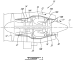
- Fig. 1 illustrates an aircraft engine depicted as a gas turbine engine 10 of a type preferably provided for use in subsonic flight, generally comprising in serial flow communication a fan 12 through which ambient air is propelled, a compressor section 14 for pressurizing the air, a combustor 16 in which the compressed air is mixed with fuel and ignited for generating an annular stream of hot combustion gases, and a turbine section 18 for extracting energy from the combustion gases.
- the fan 12, the compressor section 14, and the turbine section 18 are rotatable about a central axis 11 of the gas turbine engine 10.
- the gas turbine engine 10 comprises a high-pressure spool having a high-pressure shaft 20 drivingly engaging a high-pressure turbine 18A of the turbine section 18 to a high-pressure compressor 14A of the compressor section 14, and a low-pressure spool having a low-pressure shaft 21 drivingly engaging a low-pressure turbine 18B of the turbine section 18 to a low-pressure compressor 14B of the compressor section 14 and drivingly engaged to the fan 12.
- a high-pressure spool having a high-pressure shaft 20 drivingly engaging a high-pressure turbine 18A of the turbine section 18 to a high-pressure compressor 14A of the compressor section 14, and a low-pressure spool having a low-pressure shaft 21 drivingly engaging a low-pressure turbine 18B of the turbine section 18 to a low-pressure compressor 14B of the compressor section 14 and drivingly engaged to the fan 12.
- the gas turbine engine 10 includes a turbine exhaust case 30 located at an exhaust of the gas turbine engine 10.
- the turbine exhaust case 30 is used to mix a core flow F1 that flows through the compressor section 14, combustor 16, and turbine section 18 with a bypass flow F2 that flows within a bypass duct 19 defined radially between an exterior case 19A and a core case 19B.
- the turbine exhaust case 30 defines part of the core case 19B.
- the turbine exhaust case 30 may define crests and valleys used to favor the mixing of those two flows.
- the turbine exhaust case, TEC 30 herein after, includes an outer case 31 extending circumferentially around the central axis 11 and an inner case 32 extending circumferentially around the central axis 11.
- the outer case 31 is disposed around the inner case 32.
- the TEC 30 includes struts 33, which may be referred to as deswirling struts since they may be used to reduce a circumferential component of the core flow F1 before it is mixed with the bypass flow F2 ( Fig. 1 ).
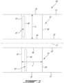
- Two struts 33 are shown in Fig. 2 . It is however understood than more than two struts 33 are present and circumferentially distributed about the central axis 11.
- the strut 33 includes an airfoil 34 that extends along a span S from an outer end 35 at the outer case 31 to an inner end 36 at the inner case 32.
- the airfoil 34 extends along a chord C from a leading edge 37 to a trailing edge 38.
- the airfoil 34 includes a pressure side 39 and a suction side 40 opposed to the pressure side 39.
- the pressure side 39 and the suction side 40 both extend along the span S from the outer end 35 to the inner end 36 and along the chord C from the leading edge 37 to the trailing edge 38.
- the pressure side 39 is concave whereas the suction side 40 is convex.
- the airfoil 34 is a cambered airfoil.
- the struts 33 are structural parts, but, as explained above, are also used to de-swirl turbine exit flow with minimal losses.
- a shape of the airfoils 34 is optimized to maximize de-swirl capability at design point (e.g., cruise).
- the optimized airfoil shape is highly dependent on the incoming swirl angle which may vary significantly between various design points. Therefore, a strut optimized for the design point may cause significant flow separation and losses at off-design point. This may cause significant reduction in the overall mission efficiency and may result in an inadequate exhaust performance if the flow separation is too large.
- the separated flow tends to increase not only losses but also engine noise.
- the strut is cambered or staggered in the direction favorable to de-swirl the flow at the design point.
- an at-design flow F3 meets the airfoil 34 at an at-design angle of attack A1 whereas, at off-design, an off-design flow F4 meets the airfoil 34 at an off-design angle of attack A2.
- the at-design flow F3 and the off-design flow F4 are located on opposite sides of the central axis 11. Therefore, at off-design conditions, the pressure side becomes defined by the suction side 40 whereas the suction side becomes defined by the pressure side 39.
- the roles of the different sides of the airfoil 34 are reversed when the flow is at the off-design point. This may create large flow separations adjacent the pressure side 39 (which in this off-design point corresponds to the suction side). Thus, a significant compromise at the design point may be required to achieve acceptable engine performance through the mission.
- the strut 33 of the present disclosure may at least partially alleviate these drawbacks.
- the strut 33 includes a slot 41 that extends from the suction side 40 to the pressure side 39.
- the slot 41 has a slot inlet 42 on the suction side 40 and a slot outlet 43 on the pressure side 39.
- the slot 41 is defined through the airfoil downstream of the leading edge 37 and extends from the slot inlet 42 on the suction side 40 to the slot outlet 43 on the pressure side 39.
- the slot 41 defines a fluid flow passage for directing fluid flow from the suction side 40 to the pressure side 39 through the airfoil 34.
- the slot inlet 42 may be located closer to the leading edge 37 than the slot outlet 43.
- the slot 41 extends along a slot axis 44 from the slot inlet 42 to the slot outlet 43.
- the slot axis 44 extends in a direction having a component parallel to the flow F3, F4.
- the slot 41 may merge into the pressure side 39, which is herein the concave side.
- a slot angle A3 defined between an exit flow axis of the slot 41, which is defined by the slot axis 44 at the slot outlet 43 of the slot 41, and the pressure side 39 at the slot outlet 43 may be at most about 15 degrees.
- a flow circulating area of the slot 41 may decrease from the slot inlet 42 to the slot outlet 43.
- walls bounding the slot 41 may merge toward one another from the slot inlet 42 at the suction side 40 to the slot outlet 43 at the pressure side 39.
- the slot inlet 42 may be located at at most about 40% of the chord C from the leading edge 37.
- the slot 41 may extend along the span S from about 20% of the span S from the inner end 36 to about 80% of the span S from the inner end 36.
- the slot 41 may extend along a greater or lesser portion of the span S in other embodiments. Extremities of the strut 33 may be free of the slot 41 for structural integrity of the strut 33.
- the slot 41 describe herein may allow a strut airfoil to be optimized for its design point yet providing adequate performance in off-design conditions.
- the slot 41 may allow an airfoil that is cambered or staggered for the design point to perform with minimal loss at off design conditions.
- the slot 41 may bring high energy flow from the suction side 40 of the airfoil, which acts as the pressure side at off-design condition, to energize and attach the separated flow at the pressure side 39, which acts as the suction side at off-design conditions.
- the slot 41 may be designed such that there will be no or minimal flow flowing through the slot 41 from pressure side to suction side at the design point.
- the converging flow circulating area of the slot 41 may maximize the flow momentum.
- the slot 41 may be designed such the flow angle at the slot outlet 43 would have a flow angle less than 15 degrees. This may increase the effectiveness of high-momentum flow and force separated low-momentum flow to reattach.
- the disclosed slot 41 has minimal impact at design point and there is no flow going from pressure side to suction side. At off-design point the slot 41 may energize the separated flow and may minimize the flow separation. It was further observed that the separated flow is minimized with the slot 41 at takeoff condition. In the present embodiment, the slot 41 does not have a significant adverse impact at the design point
- Any airfoil of the gas turbine engine 10 may use such a slot 41 as disclosed herein.
- This airfoil may be part of a stator or a rotor; the stator or rotor may be part of the compressor section 14 of the turbine section 18 without departing from the scope of the present disclosure.
Landscapes
- Engineering & Computer Science (AREA)
- Physics & Mathematics (AREA)
- Fluid Mechanics (AREA)
- Mechanical Engineering (AREA)
- General Engineering & Computer Science (AREA)
- Turbine Rotor Nozzle Sealing (AREA)
- Structures Of Non-Positive Displacement Pumps (AREA)
Abstract
Description
- The disclosure relates generally to aircraft engines and, more particularly, to struts used in such engines.
- Aerodynamic profiles of airfoils are optimized to maximize their efficiency and performance at design operating conditions. However, these same airfoils may present decreased performance when operated at off-design operating conditions. There is therefore a need to provide an airfoil that minimizes losses at off-design operating conditions.
- In one aspect, there is provided a turbine exhaust case (TEC) for a gas turbine engine, comprising: an inner case extending circumferentially about a central axis; an outer case disposed radially outward from the inner case and extending circumferentially about the central axis; struts extending between the inner case and the outer case, a strut of the struts having an airfoil extending from an inner end to an outer end along a span and from a leading edge to a trailing edge along a chord, the airfoil being cambered and having a pressure side being concave and a suction side being convex, and a slot defined through the airfoil downstream of the leading edge, the slot extending from a slot inlet on the suction side to a slot outlet on the pressure side, the slot defining a fluid flow passage for directing fluid flow from the suction side to the pressure side through the airfoil.
- The turbine exhaust case described above may include any of the following features, in any combinations.
- In some embodiments, the slot inlet is closer to the leading edge than the slot outlet.
- In some embodiments, the slot merges to the pressure side.
- In some embodiments, the struts are deswirling struts.
- In some embodiments, a flow circulating area of the slot decreases from the slot inlet to the slot outlet.
- In some embodiments, the slot inlet is located at at most 40% of the chord from the leading edge.
- In some embodiments, the slot extend from about 20% of the span from the inner end to about 80% of the span from the inner end.
- In some embodiments, an exit flow axis of the slot at the slot inlet is at most about 15 degrees relative to the pressure side.
- In another aspect, there is provided a stator for a gas turbine engine, comprising: an inner case extending circumferentially about a central axis; an outer case disposed around the inner case and extending circumferentially about the central axis; struts extending from the inner case to the outer case, a strut of the struts having an airfoil extending from an inner end to an outer end along a span and from a leading edge to a trailing edge along a chord, the airfoil having a convex side and a concave side opposed to the convex side, and a slot defined through the airfoil downstream of the leading edge, the slot extending from a slot inlet on the convex side to a slot outlet on the concave side, the slot defining a fluid flow passage for directing fluid flow from the convex side to the concave side through the airfoil.
- The stator described above may include any of the following features, in any combinations.
- In some embodiments, the slot inlet is closer to the leading edge than the slot outlet.
- In some embodiments, the slot merges to the concave side.
- In some embodiments, the struts are deswirling struts.
- In some embodiments, a flow circulating area of the slot decreases from the slot inlet to the slot outlet.
- In some embodiments, the slot inlet is located at at most 40% of the chord from the leading edge.
- In some embodiments, the slot extend from about 20% of the span from the inner end to about 80% of the span from the inner end.
- In some embodiments, an exit flow axis of the slot at the slot inlet is at most about 15 degrees relative to the concave side.
- In yet another aspect, there is provided an airfoil for an aircraft engine, comprising: a pressure side extending along a span from an inner end to an outer end and along a chord from a leading edge to a trailing edge, the pressure side being concave; a suction side extending along the span from the inner end to the outer end and along the chord from the leading edge to the trailing edge, the suction side being convex; and a slot downstream of the leading edge, the slot extending from a slot inlet on the suction side to a slot outlet on the pressure side, the slot defining a fluid flow passage for directing fluid flow from the suction side to the pressure side through the airfoil.
- The airfoil described above may include any of the following features, in any combinations.
- In some embodiments, the slot inlet is closer to the leading edge than the slot outlet.
- In some embodiments, the slot inlet is located at at most 40% of the chord from the leading edge, and extend from about 20% of the span from the inner end to about 80% of the span from the inner end.
- In some embodiments, an exit flow axis of the slot at the slot inlet is at most about 15 degrees relative to the pressure side.
- Reference is now made to the accompanying figures in which:
-
Fig. 1 is a schematic cross-sectional view of an aircraft engine depicted as a gas turbine engine; -
Fig. 2 is a cross-sectional view of a turbine exhaust case of the gas turbine engine ofFig. 1 ; and -
Fig. 3 is a cross-sectional view illustrating an airfoil of a strut of the turbine exhaust case ofFig. 1 . -
Fig. 1 illustrates an aircraft engine depicted as agas turbine engine 10 of a type preferably provided for use in subsonic flight, generally comprising in serial flow communication afan 12 through which ambient air is propelled, acompressor section 14 for pressurizing the air, acombustor 16 in which the compressed air is mixed with fuel and ignited for generating an annular stream of hot combustion gases, and aturbine section 18 for extracting energy from the combustion gases. Thefan 12, thecompressor section 14, and theturbine section 18 are rotatable about acentral axis 11 of thegas turbine engine 10. In the embodiment shown, thegas turbine engine 10 comprises a high-pressure spool having a high-pressure shaft 20 drivingly engaging a high-pressure turbine 18A of theturbine section 18 to a high-pressure compressor 14A of thecompressor section 14, and a low-pressure spool having a low-pressure shaft 21 drivingly engaging a low-pressure turbine 18B of theturbine section 18 to a low-pressure compressor 14B of thecompressor section 14 and drivingly engaged to thefan 12. It will be understood that the contents of the present disclosure may be applicable to any suitable engines, such as turboprops and turboshafts engines. - The
gas turbine engine 10 includes aturbine exhaust case 30 located at an exhaust of thegas turbine engine 10. Theturbine exhaust case 30 is used to mix a core flow F1 that flows through thecompressor section 14,combustor 16, andturbine section 18 with a bypass flow F2 that flows within a bypass duct 19 defined radially between anexterior case 19A and acore case 19B. Theturbine exhaust case 30 defines part of thecore case 19B. Theturbine exhaust case 30 may define crests and valleys used to favor the mixing of those two flows. - Referring now to
Fig. 2 , theturbine exhaust case 30 is described in more detail. The turbine exhaust case, TEC 30 herein after, includes anouter case 31 extending circumferentially around thecentral axis 11 and aninner case 32 extending circumferentially around thecentral axis 11. Theouter case 31 is disposed around theinner case 32. The TEC 30 includesstruts 33, which may be referred to as deswirling struts since they may be used to reduce a circumferential component of the core flow F1 before it is mixed with the bypass flow F2 (Fig. 1 ). Twostruts 33 are shown inFig. 2 . It is however understood than more than twostruts 33 are present and circumferentially distributed about thecentral axis 11. - One of the
struts 33 is described below using the singular form, but it will be understood that the description may apply to all of thestruts 33. - Referring to
Figs. 2-3 , thestrut 33 includes anairfoil 34 that extends along a span S from anouter end 35 at theouter case 31 to aninner end 36 at theinner case 32. Theairfoil 34 extends along a chord C from a leadingedge 37 to atrailing edge 38. Theairfoil 34 includes apressure side 39 and asuction side 40 opposed to thepressure side 39. Thepressure side 39 and thesuction side 40 both extend along the span S from theouter end 35 to theinner end 36 and along the chord C from the leadingedge 37 to thetrailing edge 38. As shown inFig. 3 , thepressure side 39 is concave whereas thesuction side 40 is convex. In other words, theairfoil 34 is a cambered airfoil. - The
struts 33 are structural parts, but, as explained above, are also used to de-swirl turbine exit flow with minimal losses. A shape of theairfoils 34 is optimized to maximize de-swirl capability at design point (e.g., cruise). The optimized airfoil shape is highly dependent on the incoming swirl angle which may vary significantly between various design points. Therefore, a strut optimized for the design point may cause significant flow separation and losses at off-design point. This may cause significant reduction in the overall mission efficiency and may result in an inadequate exhaust performance if the flow separation is too large. The separated flow tends to increase not only losses but also engine noise. - Typically, the strut is cambered or staggered in the direction favorable to de-swirl the flow at the design point. At design point, an at-design flow F3 meets the
airfoil 34 at an at-design angle of attack A1 whereas, at off-design, an off-design flow F4 meets theairfoil 34 at an off-design angle of attack A2. As shown, the at-design flow F3 and the off-design flow F4 are located on opposite sides of thecentral axis 11. Therefore, at off-design conditions, the pressure side becomes defined by thesuction side 40 whereas the suction side becomes defined by thepressure side 39. The roles of the different sides of theairfoil 34 are reversed when the flow is at the off-design point. This may create large flow separations adjacent the pressure side 39 (which in this off-design point corresponds to the suction side). Thus, a significant compromise at the design point may be required to achieve acceptable engine performance through the mission. - The
strut 33 of the present disclosure may at least partially alleviate these drawbacks. As shown inFig. 3 , thestrut 33 includes aslot 41 that extends from thesuction side 40 to thepressure side 39. Theslot 41 has aslot inlet 42 on thesuction side 40 and aslot outlet 43 on thepressure side 39. In other words, theslot 41 is defined through the airfoil downstream of the leadingedge 37 and extends from theslot inlet 42 on thesuction side 40 to theslot outlet 43 on thepressure side 39. Theslot 41 defines a fluid flow passage for directing fluid flow from thesuction side 40 to thepressure side 39 through theairfoil 34. Theslot inlet 42 may be located closer to the leadingedge 37 than theslot outlet 43. Theslot 41 extends along aslot axis 44 from theslot inlet 42 to theslot outlet 43. Theslot axis 44 extends in a direction having a component parallel to the flow F3, F4. Theslot 41 may merge into thepressure side 39, which is herein the concave side. In other words, a slot angle A3 defined between an exit flow axis of theslot 41, which is defined by theslot axis 44 at theslot outlet 43 of theslot 41, and thepressure side 39 at theslot outlet 43 may be at most about 15 degrees. As shown inFig. 3 , a flow circulating area of theslot 41 may decrease from theslot inlet 42 to theslot outlet 43. In other words, walls bounding theslot 41 may merge toward one another from theslot inlet 42 at thesuction side 40 to theslot outlet 43 at thepressure side 39. - The
slot inlet 42 may be located at at most about 40% of the chord C from the leadingedge 37. Theslot 41 may extend along the span S from about 20% of the span S from theinner end 36 to about 80% of the span S from theinner end 36. Theslot 41 may extend along a greater or lesser portion of the span S in other embodiments. Extremities of thestrut 33 may be free of theslot 41 for structural integrity of thestrut 33. - The
slot 41 describe herein may allow a strut airfoil to be optimized for its design point yet providing adequate performance in off-design conditions. Theslot 41 may allow an airfoil that is cambered or staggered for the design point to perform with minimal loss at off design conditions. At off-design conditions theslot 41 may bring high energy flow from thesuction side 40 of the airfoil, which acts as the pressure side at off-design condition, to energize and attach the separated flow at thepressure side 39, which acts as the suction side at off-design conditions. Theslot 41 may be designed such that there will be no or minimal flow flowing through theslot 41 from pressure side to suction side at the design point. - The converging flow circulating area of the
slot 41 may maximize the flow momentum. Moreover, theslot 41 may be designed such the flow angle at theslot outlet 43 would have a flow angle less than 15 degrees. This may increase the effectiveness of high-momentum flow and force separated low-momentum flow to reattach. - It was observed that the disclosed
slot 41 has minimal impact at design point and there is no flow going from pressure side to suction side. At off-design point theslot 41 may energize the separated flow and may minimize the flow separation. It was further observed that the separated flow is minimized with theslot 41 at takeoff condition. In the present embodiment, theslot 41 does not have a significant adverse impact at the design point - Any airfoil of the
gas turbine engine 10 may use such aslot 41 as disclosed herein. This airfoil may be part of a stator or a rotor; the stator or rotor may be part of thecompressor section 14 of theturbine section 18 without departing from the scope of the present disclosure. - In the context of the present disclosure, the expression "about" includes variations of plus or minus 10%.
- The embodiments described in this document provide non-limiting examples of possible implementations of the present technology. Upon review of the present disclosure, a person of ordinary skill in the art will recognize that changes may be made to the embodiments described herein without departing from the scope of the present technology. Yet further modifications could be implemented by a person of ordinary skill in the art in view of the present disclosure, which modifications would be within the scope of the present technology.
Claims (13)
- A turbine exhaust case (TEC) (30) for a gas turbine engine (10), comprising:an inner case (32) extending circumferentially about a central axis (11);an outer case (31) disposed radially outward from the inner case (32) and extending circumferentially about the central axis (11);struts (33) extending between the inner case (32) and the outer case (31), a strut of the struts (33) having
an airfoil (34) extending from an inner end (36) to an outer end (35) along a span and from a leading edge (37) to a trailing edge (38) along a chord, the airfoil (34) being cambered and having a pressure side (39) being concave and a suction side (40) being convex, anda slot (41) defined through the airfoil (34) downstream of the leading edge (37), the slot (41) extending from a slot inlet (42) on the suction side (40) to a slot outlet (43) on the pressure side (39), the slot (41) defining a fluid flow passage for directing fluid flow from the suction side (40) to the pressure side (39) through the airfoil (34). - A stator for a gas turbine engine (10), comprising:an inner case (32) extending circumferentially about a central axis (11);an outer case (31) disposed around the inner case (32) and extending circumferentially about the central axis (11);struts (33) extending from the inner case (32) to the outer case (31), a strut of the struts (33) havingan airfoil (34) extending from an inner end (36) to an outer end (35) along a span and from a leading edge (37) to a trailing edge (38) along a chord, the airfoil (34) having a convex side and a concave side opposed to the convex side, anda slot (41) defined through the airfoil (34) downstream of the leading edge (37), the slot (41) extending from a slot inlet (42) on the convex side to a slot outlet (43) on the concave side, the slot (41) defining a fluid flow passage for directing fluid flow from the convex side to the concave side through the airfoil (34).
- The TEC (30) or stator of claim 1 or 2, wherein the slot inlet (42) is closer to the leading edge (37) than the slot outlet (43).
- The TEC (30) of claim 1 or 2, wherein the slot (41) merges to the pressure or concave side (39).
- The TEC (30) or stator of any preceding claim, wherein the struts (33) are deswirling struts.
- The TEC (30) or stator of any preceding claim, wherein a flow circulating area of the slot (41) decreases from the slot inlet (42) to the slot outlet (43).
- The TEC (30) or stator of any preceding claim, wherein the slot inlet (42) is located at at most 40% of the chord from the leading edge (37).
- The TEC (30) or stator of any preceding claim, wherein the slot (41) extends from about 20% of the span from the inner end (36) to about 80% of the span from the inner end (36).
- The TEC (30) or stator of any preceding claim, wherein an exit flow axis of the slot (41) at the slot inlet (42) is at most about 15 degrees relative to the pressure side (39).
- An airfoil (34) for an aircraft engine, comprising:a pressure side (39) extending along a span from an inner end (36) to an outer end (35) and along a chord from a leading edge (37) to a trailing edge (38), the pressure side (39) being concave;a suction side (40) extending along the span from the inner end (36) to the outer end (35) and along the chord from the leading edge (37) to the trailing edge (38), the suction side (40) being convex; anda slot (41) downstream of the leading edge (37), the slot (41) extending from a slot inlet (42) on the suction side (40) to a slot outlet (43) on the pressure side (39), the slot (41) defining a fluid flow passage for directing fluid flow from the suction side (40) to the pressure side (39) through the airfoil (34).
- The airfoil (34) of claim 10, wherein the slot inlet (42) is closer to the leading edge (37) than the slot outlet (43).
- The airfoil (34) of claim 10 or 11, wherein the slot inlet (42) is located at at most 40% of the chord from the leading edge (37), and extend from about 20% of the span from the inner end (36) to about 80% of the span from the inner end (36).
- The airfoil (34) of any of claims 10 to 12, wherein an exit flow axis of the slot (41) at the slot inlet (42) is at most about 15 degrees relative to the pressure side (39).
Applications Claiming Priority (1)
| Application Number | Priority Date | Filing Date | Title |
|---|---|---|---|
| US202217934043A | 2022-09-21 | 2022-09-21 |
Publications (3)
| Publication Number | Publication Date |
|---|---|
| EP4343115A2 true EP4343115A2 (en) | 2024-03-27 |
| EP4343115A3 EP4343115A3 (en) | 2024-04-03 |
| EP4343115B1 EP4343115B1 (en) | 2026-04-08 |
Family
ID=88146917
Family Applications (1)
| Application Number | Title | Priority Date | Filing Date |
|---|---|---|---|
| EP23198927.8A Active EP4343115B1 (en) | 2022-09-21 | 2023-09-21 | Airfoil for an aircraft engine comprising a slot |
Country Status (2)
| Country | Link |
|---|---|
| EP (1) | EP4343115B1 (en) |
| CA (1) | CA3212474A1 (en) |
Family Cites Families (4)
| Publication number | Priority date | Publication date | Assignee | Title |
|---|---|---|---|---|
| US6715983B2 (en) * | 2001-09-27 | 2004-04-06 | General Electric Company | Method and apparatus for reducing distortion losses induced to gas turbine engine airflow |
| DE102017118583B4 (en) * | 2017-08-15 | 2021-01-21 | Deutsches Zentrum für Luft- und Raumfahrt e.V. | Arrangement of support struts in a downstream annulus of a gas turbine |
| CN111102012B (en) * | 2018-10-25 | 2024-07-09 | 中国科学院工程热物理研究所 | Blade adopting self-adaptive coanda jet and manufacturing method |
| JP7213103B2 (en) * | 2019-02-26 | 2023-01-26 | 三菱重工業株式会社 | wings and machines equipped with them |
-
2023
- 2023-09-13 CA CA3212474A patent/CA3212474A1/en active Pending
- 2023-09-21 EP EP23198927.8A patent/EP4343115B1/en active Active
Also Published As
| Publication number | Publication date |
|---|---|
| CA3212474A1 (en) | 2024-03-21 |
| EP4343115B1 (en) | 2026-04-08 |
| EP4343115A3 (en) | 2024-04-03 |
Similar Documents
| Publication | Publication Date | Title |
|---|---|---|
| US12320274B2 (en) | Compressor stator with leading edge fillet | |
| US10267161B2 (en) | Gas turbine engine with fillet film holes | |
| US11002141B2 (en) | Method and system for leading edge auxiliary turbine vanes | |
| EP2851516A1 (en) | Integrated turbine engine exhaust struts and mixer of turbofan engine | |
| US11274563B2 (en) | Turbine rear frame for a turbine engine | |
| EP3225852A1 (en) | Gas turbine engine fan assembly | |
| EP2899369B1 (en) | Multistage axial flow compressor | |
| US11506059B2 (en) | Compressor impeller with partially swept leading edge surface | |
| US11608782B2 (en) | Axial inertial particle separator for turbine engine | |
| US10519976B2 (en) | Fluid diodes with ridges to control boundary layer in axial compressor stator vane | |
| EP3098383B1 (en) | Compressor airfoil with compound leading edge profile | |
| US20210324797A1 (en) | Inertial particle separator for turbine engine | |
| EP3770379B1 (en) | Compressor stator | |
| EP4343115B1 (en) | Airfoil for an aircraft engine comprising a slot | |
| EP3354848A1 (en) | Inter-turbine ducts with multiple splitter blades | |
| EP3012442A1 (en) | Integrated turbine exhaust struts and mixer of turbofan engine | |
| EP4144959A1 (en) | Fluid machine for an aircraft engine and aircraft engine | |
| CN112943383A (en) | Turbine nozzle with airfoil having curved trailing edge | |
| US11639666B2 (en) | Stator with depressions in gaspath wall adjacent leading edges | |
| US11415012B1 (en) | Tandem stator with depressions in gaspath wall | |
| EP3150836A1 (en) | Integrated tec/mixer strut axial position |
Legal Events
| Date | Code | Title | Description |
|---|---|---|---|
| PUAI | Public reference made under article 153(3) epc to a published international application that has entered the european phase |
Free format text: ORIGINAL CODE: 0009012 |
|
| STAA | Information on the status of an ep patent application or granted ep patent |
Free format text: STATUS: THE APPLICATION HAS BEEN PUBLISHED |
|
| PUAL | Search report despatched |
Free format text: ORIGINAL CODE: 0009013 |
|
| AK | Designated contracting states |
Kind code of ref document: A2 Designated state(s): AL AT BE BG CH CY CZ DE DK EE ES FI FR GB GR HR HU IE IS IT LI LT LU LV MC ME MK MT NL NO PL PT RO RS SE SI SK SM TR |
|
| AK | Designated contracting states |
Kind code of ref document: A3 Designated state(s): AL AT BE BG CH CY CZ DE DK EE ES FI FR GB GR HR HU IE IS IT LI LT LU LV MC ME MK MT NL NO PL PT RO RS SE SI SK SM TR |
|
| RIC1 | Information provided on ipc code assigned before grant |
Ipc: F01D 5/14 20060101AFI20240227BHEP |
|
| STAA | Information on the status of an ep patent application or granted ep patent |
Free format text: STATUS: REQUEST FOR EXAMINATION WAS MADE |
|
| 17P | Request for examination filed |
Effective date: 20241003 |
|
| RBV | Designated contracting states (corrected) |
Designated state(s): AL AT BE BG CH CY CZ DE DK EE ES FI FR GB GR HR HU IE IS IT LI LT LU LV MC ME MK MT NL NO PL PT RO RS SE SI SK SM TR |
|
| GRAP | Despatch of communication of intention to grant a patent |
Free format text: ORIGINAL CODE: EPIDOSNIGR1 |
|
| STAA | Information on the status of an ep patent application or granted ep patent |
Free format text: STATUS: GRANT OF PATENT IS INTENDED |
|
| INTG | Intention to grant announced |
Effective date: 20251031 |
|
| GRAS | Grant fee paid |
Free format text: ORIGINAL CODE: EPIDOSNIGR3 |
|
| GRAA | (expected) grant |
Free format text: ORIGINAL CODE: 0009210 |
|
| STAA | Information on the status of an ep patent application or granted ep patent |
Free format text: STATUS: THE PATENT HAS BEEN GRANTED |
|
| AK | Designated contracting states |
Kind code of ref document: B1 Designated state(s): AL AT BE BG CH CY CZ DE DK EE ES FI FR GB GR HR HU IE IS IT LI LT LU LV MC ME MK MT NL NO PL PT RO RS SE SI SK SM TR |
|
| REG | Reference to a national code |
Ref country code: CH Ref legal event code: F10 Free format text: ST27 STATUS EVENT CODE: U-0-0-F10-F00 (AS PROVIDED BY THE NATIONAL OFFICE) Effective date: 20260408 Ref country code: GB Ref legal event code: FG4D |
|
| REG | Reference to a national code |
Ref country code: DE Ref legal event code: R096 Ref document number: 602023014791 Country of ref document: DE |