EP4343105A1 - Determination of an updated drilling plan - Google Patents
Determination of an updated drilling plan Download PDFInfo
- Publication number
- EP4343105A1 EP4343105A1 EP22196730.0A EP22196730A EP4343105A1 EP 4343105 A1 EP4343105 A1 EP 4343105A1 EP 22196730 A EP22196730 A EP 22196730A EP 4343105 A1 EP4343105 A1 EP 4343105A1
- Authority
- EP
- European Patent Office
- Prior art keywords
- drilling
- drill rig
- model
- holes
- face
- Prior art date
- Legal status (The legal status is an assumption and is not a legal conclusion. Google has not performed a legal analysis and makes no representation as to the accuracy of the status listed.)
- Pending
Links
Images


Classifications
-
- E—FIXED CONSTRUCTIONS
- E21—EARTH OR ROCK DRILLING; MINING
- E21B—EARTH OR ROCK DRILLING; OBTAINING OIL, GAS, WATER, SOLUBLE OR MELTABLE MATERIALS OR A SLURRY OF MINERALS FROM WELLS
- E21B7/00—Special methods or apparatus for drilling
- E21B7/02—Drilling rigs characterised by means for land transport with their own drive, e.g. skid mounting or wheel mounting
- E21B7/022—Control of the drilling operation; Hydraulic or pneumatic means for activation or operation
-
- E—FIXED CONSTRUCTIONS
- E21—EARTH OR ROCK DRILLING; MINING
- E21B—EARTH OR ROCK DRILLING; OBTAINING OIL, GAS, WATER, SOLUBLE OR MELTABLE MATERIALS OR A SLURRY OF MINERALS FROM WELLS
- E21B7/00—Special methods or apparatus for drilling
- E21B7/02—Drilling rigs characterised by means for land transport with their own drive, e.g. skid mounting or wheel mounting
- E21B7/025—Rock drills, i.e. jumbo drills
Definitions
- Various example embodiments generally relate to the field of drilling. Some example embodiments relate to updating a drilling plan based on 3D models of a drilling face and a drill rig.
- Drill rigs may be used for drilling holes in a drilling surface such as for example a rock face.
- an underground drill rig may be configured to drill holes for explosives in mining applications.
- a surface drill rig may be configured for the same purpose at terrestrial environment. In such applications it may be desired to carefully plan locations of the holes such that the intended result is achieved by applying the explosives.
- Drill rigs may be equipped with one or more booms to enable holes to be drilled in the planned locations.
- a drilling control apparatus may comprise: at least one processor; and at least one memory including computer program code, the at least one memory and the computer program code configured to, with the at least one processor, cause the apparatus at least to: obtain a three-dimensional (3D) model of a drilling face; obtain a 3D model of at least one component of a drill rig and a kinematic model of the drill rig; obtain a drilling plan indicative of a plurality of start points and end points of a plurality of holes to be drilled on the drilling face; perform a simulation of the drilling plan based on the 3D model of the drilling face, the 3D model of the at last one component of the drill rig, and the kinematic model of the drill rig; detect, based on the simulation, a simulated collision between the at least one component of the drill rig and the drilling face or between components of the drill rig, wherein the simulated collision is associated with simulated drilling of at least one of the plurality of holes; and determine
- the computer program code may be configured to, with the at least one processor, cause the apparatus to: maintain, in the updated drilling plan, an end point of the at least one of the plurality of holes, wherein the end point of the at least one of the plurality of holes was included in the drilling plan, adjust the end point of the at least one of the plurality of holes towards the adjusted start point of the at least one of the plurality of holes, or adjust the end point of the at least one of the plurality of holes towards the adjusted start point such that a distance between the adjusted start point and the end point is substantially equal to a distance between the start point and the end point of the at least one of the plurality of holes.
- the computer program code may be configured to, with the at least one processor, cause the apparatus to: determine, based on the simulation, a location of a drilling unit of the drill rig, wherein the location of the drilling unit is associated with the simulated collision; determine a position for the drilling unit to reach the end point of the at least one of the plurality of holes from the determined location of the drilling unit; and adjust the start point of the at least one of the plurality of holes based on the determined position.
- the computer program code may be configured to, with the at least one processor, cause the apparatus to: determine at least one candidate start point for the at least one of the plurality of holes; perform, based on the 3D model of the drilling face, the 3D model of the at last one component of the drill rig, and the kinematic model of the drill rig, a second simulation of drilling the at least one of the plurality of holes with the at least one candidate start point; and adjust the start point of the at least one of the plurality of holes based on the second simulation such that no simulated collision occurs between the at least one component of the drill rig and the drilling face or between the components of the drill rig.
- the computer program code may be configured to, with the at least one processor, cause the apparatus to: adjust, based on the 3D model of the drilling face, the 3D model of the at least one component of the drill rig, and the kinematic model of the drill rig, the start point of the at least one of the plurality of holes such that no simulated collision occurs between the at least one component of the drill rig and the drilling face or between the components of the drill rig.
- the computer program code may be configured to, with the at least one processor, cause the apparatus to: perform a mapping between the plurality of start points and end points and the 3D model of the drilling face.
- the at least one component of the drill rig comprises at least one of the following: a first boom, a second boom, a first drilling unit coupled to the first boom, a second drilling unit coupled to the second boom, at least one boom part of the first boom, or at least one boom part of the second boom.
- the computer program code may be configured to, with the at least one processor, cause the apparatus to: scan the drilling face to obtain the 3D model of the drilling face.
- the computer program code may be configured to, with the at least one processor, cause the apparatus to: scan the drilling face, in response to detecting the drill rig to reach a planned drilling position.
- the computer program code may be configured to, with the at least one processor, cause the apparatus to: initiate drilling of the plurality of holes based on the updated drilling plan.
- the apparatus comprises the drill rig.
- the computer program code may be configured to, with the at least one processor, cause the apparatus to: receive the 3D model of the drilling face from the drill rig to obtain the 3D model of the drilling face; and transmit the updated drilling plan to the drill rig.
- the apparatus comprises a drilling control device, wherein the drilling control device is external to the drill rig.
- a method for controlling a drill rig may comprise: obtaining a three-dimensional (3D) model of a drilling face; obtaining a 3D model of at least one component of a drill rig and a kinematic model of the drill rig; obtain a drilling plan indicative of a plurality of start points and end points of a plurality of holes to be drilled on the drilling face; performing a simulation of the drilling plan based on the 3D model of the drilling face, the 3D model of the at last one component of the drill rig, and the kinematic model of the drill rig; detecting, based on the simulation, a simulated collision between the at least one component of the drill rig and the drilling face or between components of the drill rig, wherein the simulated collision is associated with simulated drilling of at least one of the plurality of holes; and determining an updated drilling plan comprising an adjusted start point of the at least one of the plurality of holes, in response to detecting the simulated collision.
- 3D three-dimensional
- the method may comprise: maintaining, in the updated drilling plan, an end point of the at least one of the plurality of holes, wherein the end point of the at least one of the plurality of holes was included in the drilling plan, adjusting the end point of the at least one of the plurality of holes towards the adjusted start point of the at least one of the plurality of holes, or adjusting the end point of the at least one of the plurality of holes towards the adjusted start point such that a distance between the adjusted start point and the end point is substantially equal to a distance between the start point and the end point of the at least one of the plurality of holes.
- the method may comprise: determining, based on the simulation, a location of a drilling unit of the drill rig, wherein the location of the drilling unit is associated with the simulated collision; determine a position for the drilling unit to reach the end point of the at least one of the plurality of holes from the determined location of the drilling unit; and adjust the start point of the at least one of the plurality of holes based on the determined position.
- the method may comprise: determining at least one candidate start point for the at least one of the plurality of holes; performing, based on the 3D model of the drilling face, the 3D model of the at last one component of the drill rig, and the kinematic model of the drill rig, a second simulation of drilling the at least one of the plurality of holes with the at least one candidate start point; and adjusting the start point of the at least one of the plurality of holes based on the second simulation such that no simulated collision occurs between the at least one component of the drill rig and the drilling face or between the components of the drill rig.
- the method may comprise: adjusting, based on the 3D model of the drilling face, the 3D model of the at least one component of the drill rig, and the kinematic model of the drill rig, the start point of the at least one of the plurality of holes such that no simulated collision occurs between the at least one component of the drill rig and the drilling face or between the components of the drill rig.
- the method may comprise: perform a mapping between the plurality of start points and end points and the 3D model of the drilling face.
- the at least one component of the drill rig comprises at least one of the following: a first boom, a second boom, a first drilling unit coupled to the first boom, a second drilling unit coupled to the second boom, at least one boom part of the first boom, or at least one boom part of the second boom.
- the method may comprise: scanning the drilling face to obtain the 3D model of the drilling face.
- the method may comprise: scanning the drilling face, in response to detecting the drill rig to reach a planned drilling position.
- the method may comprise: initiating drilling of the plurality of holes based on the updated drilling plan.
- the method may be performed by the drill rig.
- the method may comprise: receiving the 3D model of the drilling face from the drill rig to obtain the 3D model of the drilling face; and transmitting the updated drilling plan to the drill rig.
- the method may be performed by a drilling control device, wherein the drilling control device is external to the drill rig.
- an apparatus may comprise means for performing a method according to the second aspect, or any example embodiment thereof.
- a computer program or a computer program product may comprise instructions, which when executed by an apparatus, cause the apparatus perform a method according to the second aspect, or any example embodiment thereof.
- a (non-transitory) computer readable medium may comprise program code that, when executed by an apparatus, cause the apparatus to perform a method according to the second aspect, or any example thereof.
- Drill rigs may be operated based on a drilling plan to achieve the desired result, for example, to extend a tunnel by applying explosives at the drilled holes.
- the drilling plan may comprise start point(s) and end point(s) for one or a plurality of holes.
- a human operator may control the drill rig locally, e.g., sitting in the cabin of the drill rig, or via remote control. The operator may monitor and manually control boom(s) of the drill rig in order to avoid collisions between the boom(s) and the drilling surface (e.g. walls of the tunnel) or between the booms themselves.
- a hole can not be drilled without a collision, for example, if the hole is not reachable, the operator may use his/her own judgement to manually position the boom at an adjusted position and to drill the hole from that position.
- the adjusted positions determined by the operator may not be optimal for blasting the surface.
- Reactive boom collision monitoring/avoidance systems may be used to avoid collisions. However, in that case the decisions may be made reactively and therefore it may not be possible to predict whether holes of the drilling plan are reachable or drillable. A hole may be unreachable, for example, if the start point of the planned hole is inside the drilling face. In this case, the boom can not reach the target, regardless of whether collision avoidance is applied or not.
- Example embodiments of the present disclosure enable the drilling plan to be updated before drilling such that the desired result is still achieved when applying explosives at the drilled holes. Collisions may be therefore avoided and efficiency of the drilling procedure is improved.
- an apparatus may obtain 3D models of a drilling face and component(s) of a drill rig, a kinematic model of the drill rig, and a drilling plan indicative of start and end points of a plurality of holes to be drilled on the drilling face.
- the apparatus may perform a simulation of the drilling plan based on the 3D models of the drilling face and the component(s) of the drill rig and the kinematic model of the drill rig, and detect, based on the simulation, a simulated collision between the component(s) of the drill rig and the drilling face or between the components of the drill rig, wherein the simulated collision is associated with simulated drilling of at least one of the plurality of holes.
- the apparatus may determine an updated drilling plan comprising an adjusted start point of the at least one of the plurality of holes, in response to detecting the simulated collision.
- FIG. 1 illustrates an example of a drill rig comprising a drilling controller.
- drill rig 100 is illustrated as an underground drill rig, example embodiments of the present disclosure may be applied also to other type of drilling machines, such as for example surface drill rigs.
- Drill rig 100 may comprise a rock drilling rig.
- Drill rig 100 may be an automated drill rig, for example an automated underground drill rig or an automated surface drill rig.
- An automated mining vehicle, for example an automated underground drill rig, operating in an automatic mode may be configured to, for example, receive a task to be performed, perceive the environment of the mobile mining vehicle and autonomously perform the task while taking the environment into account.
- An automated mining vehicle operating in an automatic mode may be configured to operate independently but may be taken under external control at certain operation areas or conditions, such as during states of emergencies.
- Axis x represents the forward driving direction of drill rig 100.
- Axis z represents the vertical direction, in this example towards the roof of the tunnel.
- Drill rig 100 may comprise a movable carrier 110 and at least one boom 120 connected to movable carrier 110.
- Movable carrier 110 may comprise equipment for moving or stabilising drill rig 100, such as for example a motor, wheels, or stabilizer jacks. Even though two booms 120 have been illustrated in FIG. 1 , drill rig 100 may in general comprise one or a plurality (e.g. two, three, four,...) of booms 120.
- a drilling unit 130 may be coupled to a distal end portion of boom 120.
- drilling unit 130 may comprise a feeding system configured to keep a drill bit in contact with drilling face 140 and to enable a drill rod to move along a feed beam during drilling.
- Boom(s) 120 may comprise a plurality of boom parts coupled to each other, movable carrier 110, and/or drilling unit 130 by joint(s) 122. Controllable joints enable drilling unit 130 to be placed at a desired position and orientation with respect to drilling face 140.
- Drilling face 140 may comprise at least part of the wall(s) of a tunnel, at least part of the roof of the tunnel, and/or at least part of the floor of the tunnel, for example near the end of the tunnel.
- Drilling face 140 may comprise an in-situ rock surface of the tunnel, for example near a drilling position of drill rig 100.
- the in-situ rock face may comprise the end of the tunnel and at least some of the walls, floor, and/or roof of the tunnel near the end of the tunnel.
- Drill rig 100 may comprise at least one sensor 112 for scanning environment of drill rig 100, for example, drilling face 140.
- Sensor 112 may include for example one or more of the following: a camera, a radio detection and ranging (radar) sensor, or a light detection and ranging (lidar) sensor.
- Sensor 112 may be configured to scan drilling face 140, for example to obtain a three-dimensional (3D) model of drilling face 140.
- a camera may be used to extract depth information of drilling face 140, for example by comparing two images taken at slightly different position (e.g., by two camera units).
- sensor 112 may comprise a time-of-flight (ToF) camera, which may be configured to determine a distance between the camera and points of drilling face 140 by measuring a round-trip time of an artificial light signal provided by a laser or a light-emitting diode (LED).
- a lidar sensor may be configured to determine a distance to different points of drilling face 140 by targeting drilling face 140 with a laser and measuring the time for the reflected light to return to a receiver of the lidar sensor.
- a radar sensor may be configured to transmit electromagnetic energy towards drilling face 140 and to observe the echoes returned from drilling face 140 to determine distances to different points of drilling face 140.
- the 3D model of drilling face may be therefore fixed to, or known in relation to, a coordinate system of drill rig 100.
- Drill rig 100 may be configured to scan drilling face 140 using the at least one sensor 112, for example in response to detecting drill rig 100 to reach a planned drilling position.
- the 3D model of drilling face 140 may be therefore represented with respect to the planned drilling position. This enables mapping between points of a coordinate frame that is stationary with respect to drill rig 100 and a coordinate frame of drilling face 140.
- the planned drilling position may be included in the drilling plan, which may be locally pre-configured at drill rig 100 (e.g., stored at a memory of drill rig 100) or received from another device (e.g., a remote drilling controller).
- the 3D model of drilling face may be provided as point-cloud data indicative of the positions of drilling face 140.
- Drill rig 100 may comprise a drilling controller 114.
- Drilling controller 114 may be communicatively coupled to sensor 112, for example to receive scanned sensor data from sensor 112, or, to request sensor 112 to initiate scanning of drilling face 140.
- Drilling controller 114 may be for example provided as a software application residing on a memory and being executable by a processor.
- An example of an apparatus suitable for implementing drilling controller 114 is provided in FIG. 7 .
- Drilling controller 114 may comprise, or be communicatively coupled to, various functions, blocks, or applications for implementing functionality of drilling controller 114.
- drilling controller 114 may comprise or be communicatively coupled to a data management server, which may be configured to store information of drilling plan(s), tunnel lines, point cloud or mesh presentations of tunnel lines or profiles, a mine map point cloud, or the like.
- Drilling controller 114 may comprise a drilling navigation application configured to control or enable a human user to control navigation of drill rig 100, for example to move it to the planned drilling position and to determine a relative location of the drilling plan in relation to drill rig 100 and drilling face 140.
- Drilling controller 114 may comprise a drilling simulator configured to perform simulations of movement of component(s) of drill rig, for example based on a request from the drilling navigation application. Simulations may be used for example to obtain pre-knowledge of boom positions for a drilling round before real movement of booms at drilling face 140. Simulation enables to determine a collision-free design for the drill plan.
- Drilling controller 114 may be configured to determine and/or maintain the drilling plan, a 3D model of at least one component of drill rig 100 (e.g., a 3D model of boom(s) 120 and/or a 3D model of drilling unit(s) 130).
- the 3D model of the at least one component of drill rig 100 may comprise 3D geometry data of the component(s), obtained for example from a computer aided design (CAD) model of the respective physical component(s).
- Drilling controller 114 may be also configured to determine and/or maintain a kinematic model of drill rig 100.
- the kinematic model may comprise information on dimensions of boom(s) 120, or parts thereof, characteristics of joint(s) 122 (e.g.
- the kinematic model may thus enable modelling movement of the component(s) of drill rig 100, for example boom(s) 120 and/or associated drilling unit(s) 130.
- the 3D model(s) of the at least one component may be provided as point cloud data indicative of the surface of the at least one component.
- Point cloud data may comprise a plurality of data points representing, for example, distances between drill rig 100 and objects in the environment of drill rig 100 at a particular time instance.
- An individual point included in a point cloud may be presented by, for example, X and Y coordinates, or X, Y and Z coordinates with respect to a particular coordinate frame.
- drilling controller 114 may be external to drill rig 100, for example at an external drilling control device 202, as illustrated in FIG. 2 .
- Drilling control device 202 may be for example a server located remote from drill rig 100, for example outside the tunnel. Functionality of drilling controller 114 may be also distributed between drill rig 100, for example a local drilling controller of drill rig 100, and external drilling control device 202. Information may be exchanged between drilling controller 114 and drill rig 100 over a communication interface including any suitable wireless or wired connection. Examples of suitable communication interfaces are described with reference to FIG. 7 .
- Drilling controller 114 may be configured to determine and/or maintain the drilling plan.
- the 3D and kinematic models of drill rig 100 may be locally stored at drilling controller 114, for example based on pre-configuration of the models.
- drilling controller 114 may be configured to receive one or more of the models from drill rig 100 or the data management server.
- Drilling controller 114 may also be configured to receive, for example from drill rig 100, the scanned sensor data of sensor 112, which drilling controller 114 may be configured to use for generating a 3D model of drilling face 140.
- drilling controller 114 may be configured to obtain the 3D model by receiving a 3D model of drilling face 140 generated by drill rig 100 based on the scanned sensor data.
- Example embodiments of the present disclosure may be thus implemented locally at drill rig 100 and/or at a remote drilling control system.
- the drilling plan may comprise one or a plurality of holes 150 with respective start points ( s n ) and end points ( e n ).
- the start and end points of the holes may be represented in a reference coordinate frame used for planning the drilling.
- drilling controller 114 may be configured to map the start and end points of the holes 150 to the 3D model of drilling face 140 obtained based the scanning of drilling face 140 by drill rig 100.
- drilling controller 114 may be configured to map the scanned 3D model of drilling face 140 to the coordinate system used to present the start and end points of the holes 150.
- drilling controller 114 may be configured to perform a mapping between start and end points and the 3D model of drilling face 140. This helps to simulate of the drilling plan at the 3D model of drilling face 140. It is however noted that synchronization between the reference coordinate frame and the coordinate frame of drill rig 100 may be performed in any suitable manner.
- FIG. 1 Two examples of non-drillable holes are provided in FIG. 1 .
- Hole 151 can not be drilled, because its start point ( s 1 ) is below the ground level of the tunnel.
- hole 152 can not be drilled due to bump 142 located at the bottom surface of the tunnel, because bump 142 prevents drilling unit 130 from reaching the desired drilling position.
- Such situations may be however detected by simulations using the 3D model of drilling face 140, the 3D model of component(s) of drill rig 100, and the kinematic model of drill rig 100. Start points of these holes may be then adjusted to enable drilling to the original end point, as will be further described below.
- drilling controller 114 may be located at drill rig 100 or external to drill rig, the simulation may be performed as an onboard simulation at drill rig 100 or as a remote simulation at external drilling control device 202 comprising drilling controller 114.
- FIG. 3 illustrates an example of a drilling unit.
- Drilling unit 130 may comprise a feed beam 131 and a rock drilling machine 132 supported on it.
- the rock drilling machine 132 may comprise a shank at a front end of the rock drilling machine 132 for connecting a tool, such as for example drill rod 133 comprising, or configured to be coupled to, drill bit 134.
- drilling unit 130 may comprise one or more rod handling devices 135, such as for example a tool hold device, a tool changing apparatus or manipulator, and/or a tool magazine or storage.
- one or more additional devices 136 may be supported to the feed beam 131.
- the 3D model of the at least one component of drill rig 100 may comprise 3D models of any of the above described components of drilling unit 130.
- a 3D model of a component of drill rig 100 need not be an accurate 3D model of the component.
- approximate 3D model(s) may be used to represent approximate dimensions of the component(s) for the purpose of simulating collisions. This may reduce computational complexity, while still providing sufficient accuracy.
- FIG. 4 illustrates an example of a flow chart for determining an updated drilling plan. Some operations of the flow chart may be performed by drilling controller 114, which may be located at drill rig 100 or external to drill rig 100, for example at external drilling control device 202. Some of the operations, such as scanning drilling face or the drilling itself, may be performed by drill rig 100.
- drill rig 100 may be configured to scan drilling face 140, for example with sensor 112. Drill rig 100 may be configured to generate a 3D model of drilling face 140 based on sensor data obtained by scanning drilling face 140.
- the 3D model 402 of drilling face 140 may be provided to drilling controller 114, which may be configured to store the model at a memory.
- drilling controller 114 may be configured to generate the 3D model of drilling face 140 based on sensor data provided by sensor 112.
- Drilling controller 114 may be configured to obtain a 3D model 403 of at least one component of drill rig 100, including for example 3D model(s) of boom 120 and/or drilling unit 130.
- Drilling controller 114 may be configured to obtain kinematic model 404 of drill rig 100 or part(s)/component(s) thereof. Drilling controller 114 may be configured to obtain drilling plan 405. 3D model 403, kinematic model 404, and/or drilling plan 405 may be retrieved from memory of drilling controller 114 or received from another device, for example from the data management server. As described above, drilling plan 405 may be indicative of start points ( s n ) and end points ( e n ) of holes 150 planned to be drilled on drilling face 140.
- drilling controller 114 may be configured to initiate analysis of a next hole of the drilling plan.
- drilling controller 114 may be configured to determine whether the analysed hole is drillable. Drilling controller 114 may be configured to perform simulation of the analysed hole of drilling plan 406. The simulation may be based on the 3D model 402 of drilling face 140, 3D model 403 of the at least one component of drill rig 100, and kinematic model 404 of drill rig 100. Simulation of drilling plan 405 may include determining whether a simulated collision happens between component(s) of drill rig 100 (e.g. drilling unit 130, boom 120, or part(s) thereof) and drilling face 140. Simulation of drilling plan 405 may include determining whether a simulated collision happens between components of drill rig 100.
- component(s) of drill rig 100 e.g. drilling unit 130, boom 120, or part(s) thereof
- Simulation of drilling plan 405 may include determining whether a simulated collision happens between components of drill rig 100.
- a collision may comprise unintentional (physical) contact between a first object and a second object.
- the first object may comprise a first part of drill rig 100.
- the second object may comprise a second part of drill rig 100 or an object in the environment of drill rig 100.
- Drilling controller 114 be configured to detect a simulated collision for example between a first boom of drill rig 100 and drilling face 140, a first boom and a second boom of drill rig 100, a first drilling unit (coupled to the first boom) and drilling face 140, a first drilling unit (coupled to the first boom of drill rig 100) and a second drilling unit (coupled to the second boom of drill rig 100), the first drilling unit and the second boom (or a part thereof), or at least one boom part of the first or second boom and drilling face 140.
- a simulated collision may be detected, if point cloud data of the component(s) of drill rig 100 and/or drilling face 140 overlap when drilling unit 130 is placed, or moved to, the desired drilling position.
- Drilling controller 114 may be configured to determine the desired position of drilling unit 130 based on the start and end points of the analysed hole.
- FIG. 5 illustrates an example of a simulated collision.
- Axis x represents again the forward driving direction of drill rig 100.
- Axis y represents the other horizontal axis, in this example towards the left wall of the tunnel with respect to the forward driving direction.
- Drilling controller 114 may be configured to simulate movement of drilling unit 130 from its initial position towards the left wall. At some point, drilling controller 114 may be configured to detect the point cloud data of drilling unit 130 and the point cloud data of drilling face 140 to overlap. Based on the detected collision, drilling controller 114 may be configured to determine a possible position (e.g. the closest possible position to drilling surface 140) for drilling unit 130 for drilling the analysed hole. It is however noted that movement to the desired drilling position may be prevented by collision of component(s) other than drilling unit 130. For example, a simulated collision may be detected between boom 120 and drilling face 140 (or another boom), even if drilling unit 130 would fit to the desired drilling position.
- Determining whether the analysed hole is drillable may comprise determining a resulting end point 502, when drilling from the determined possible position of drilling unit 130 and initiating drilling from the planned start point 501. If the resulting end point 502 is not the same as, or within a threshold distance from, the planned end point 503, drilling controller 114 may be configured to determine the hole to be non-drillable.
- drilling controller 114 may move back to operation 406 to analyse a next hole of drilling plan 405. If the hole is drillable (e.g., no simulated collision detected), drilling controller 114 may move to operation 408 to adjust the start point of the hole.
- drilling controller 114 may be configured to adjust the start point of the analysed hole.
- FIG. 5 also illustrates an update of a hole of drilling plan 405.
- drilling controller 114 may be configured to determine an adjusted start point 504 for the analysed hole.
- the adjusted start point may be determined such that drilling to the planned end point 503 is enabled from the determined possible position of drilling unit 130.
- the planned end point 503 may be however maintained in drilling plan 405. Maintaining the end point helps to get a successful blast, resulting in, at least approximately, the desired profile of the tunnel. It might be however possible to always maintain the end point, for example if the drill bit 134 would not reach the planned end point 503 when starting drilling from the adjusted start point 504.
- Drilling controller 114 may therefore be configured to adjust the planned end point 503 towards the adjusted start point 504, for example based on length of drill rod 133 or in general the available drilling depth of drilling unit 130. Drilling controller 114 may alternatively be configured to adjust the planned end point 503 towards the adjusted start point 504 such that the distance between the adjusted start point 504 and the adjusted end point is substantially equal to the distance between the planned start point 501 and the planned end point 503. This helps to get a successful blast and to keep the resulting tunnel profile at least close to the desired profile.
- drilling controller 114 may be configured to determine, based on the simulation, a location of drilling unit 130, where the location is associated with the simulated collision.
- the location may be the exact location of the simulated collision, or a location in proximity of the collision location.
- the location of drilling unit 130 may be represented in any suitable manner, for example by locations of two points of drilling unit 130, or a location of one point of drilling unit 130 associated with a pose, for example orientation with respect to one or more axes (e.g. yaw, pitch, roll).
- drilling controller 114 may be configured to determine a position (e.g., location and/or orientation) that enables to reach the planned end point 503 from the determined location.
- Drilling controller 114 may then be configured to determine the adjusted start point 504 of the analysed hole based on the determined rotation such that the adjusted start point 504 lies between the planned end point 503 and the drilling unit 130 (e.g. drill bit 134) when drilling unit 130 is rotated according to the determined rotation.
- This example may comprise manipulating the positioning setpoint, by drilling controller 114, for example, to cause drill bit 134 to move to the planned start point 501.
- One setpoint may represent a point within a trajectory for moving a component of drill rig 100, for example, drill bit 134, to a target position.
- a set of positioning setpoints may be defined between an initial position of the component and the target position to define the trajectory.
- the target position may be the planned start point 501.
- a last set point may be the planned start point.
- a rotation setpoint may similarly represent of a point of the component, when rotating the component to a planned orientation.
- Drilling controller 114 may be configured to, for example, simulate movement of boom 120 and/or other component(s) of drill rig 100 towards the start point of the analysed hole, for example with a predefined speed. Drilling controller 114 may be configured to determine a target position of drilling unit 130 based on the start point of the analysed hole. Drilling controller 114 may be configured to determine a target rotation as a function of the planned start and end points, using geometrical calculations. Drilling controller 114 may be configured to update the target position to be the current position of drilling unit 130, if a simulated collision is detected (e.g. based on a minimum threshold for the distance between drilling unit 130 and drilling face 140).
- Drilling controller 114 may be configured to update the target rotation such that it is determined as a function of the planned end point and the current position of drilling unit 130. Drilling controller 114 may be configured to manipulate final position target opposite to obstacle if the distance falls too low. Drilling controller 114 may be configured to split the point cloud and predefine correct yielding direction for each point cloud. For example, the point cloud may be split to a plurality of subsets, wherein each subset is associated with a different yielding direction away from drilling face 140, or in general, an obstacle. Drilling controller 104 may determine the yielding direction by the surface normal of the 3D model of drilling face 140 at the point of collision.
- a first subset of the point could for which the closest portion of drilling face 140 is a first portion of the drilling face (e.g. the left wall with respect to the forward driving direction of drill rig 110), may be associated with a first yielding direction (e.g. to the right).
- Different yielding directions may be therefore associated with different subsets of the point cloud, for example the left wall, the right wall, the roof, the floor, or the end of the tunnel.
- Drilling controller 114 may determine the updated start point by moving the start point to the yielding direction associated with the location (in the point cloud data) of the simulated collision. This enables to speed up generation of the updated drilling plan, because the expected direction of adjusting the start point is readily available after detecting the simulated collision.
- FIG. 6 illustrates an example of weighted control of at least one component of a drill rig.
- Controlling (simulated) movement of the component(s) of drill rig 100 may be based on weighting of control signals of a collision avoidance system 602 configured to avoid collisions and a positioning system 604 configured to move the component(s) in order to reach the planned drilling position, for example such that drill rig 100 is enabled to reach both the start and end point of the associated hole.
- positioning system 604 may be configured to cause an attractive force via virtual (simulated) valves 606 that causes component(s) of drill rig 100 to move towards an obstacle close to the planned drilling position, for example part of drilling face 140 or another component of drill rig 100.
- Collision avoidance system 602 may be configured to cause a rejective force via virtual valves 606 that restricts or prevents movement of the component(s) of drill rig 100 to towards the obstacle. Hybrid positioning may be hence applied when the component(s) are in a rejection zone (e.g. within a threshold distance from the obstacle). A collision-free drilling position may be determined based on a stabilization point of the attractive and rejective forces.
- virtual valves 606 may be configured to model real valves, for example by providing motion requests or position change requests for kinematic joint(s) in desired directions.
- a position setpoint may be obtained from collision avoidance system 602.
- a rotation setpoint may be obtained from positioning system 604.
- the control signals of collision avoidance system 602 and positioning system 604 may be weighted with multiplicative weights w 1 and w 2 , respectively. Results of the multiplications may be summed to obtain a combined control signal for virtual valves 606.
- w 2 1 - w 1 .
- drilling controller 114 may be configured to test different start points to find a start point that enables collision free drilling to the planned end point 503.
- Drilling controller 114 may be configured to determine candidate start point(s), for example randomly selected point(s) around the planned start point 501.
- Drilling controller 114 may then be configured to perform a second simulation, again based on the 3D model of drilling face 140, the 3D model of the component(s) of drill rig 100 (e.g. boom 120 and/or drilling unit 130), and the kinematic model of drill rig 100. This simulation may be performed for one of the candidate start points at a time to detect whether that candidate start point enables collision-free drilling of the analysed hole.
- drilling controller 114 may be configured to iterate the simulation over the candidate start points starting from the point closest to the planned start point 501 and continuing in an increasing order of distance to the planned start point 501.
- drilling unit may be configured to determine the adjusted start point to be the first identified candidate start point that enables collision-free drilling.
- drilling controller 114 may be configured to iterate the simulation with the different candidate start points without considering their distance to the planned start point 501. In this case, drilling controller 114 may be configured to continue iterating the candidate start points even if it finds a start point that enables collision-free drilling.
- the adjusted start point may be selected to be the candidate start point that is closest to the planned start point 105 and that enables collision-free drilling.
- the start point may be therefore adjusted such that no simulated collision occurs with the adjusted start point.
- the adjusted point may be point 504.
- the start point of the analysed hole may be adjusted based on analytically finding a point that enables collision-free drilling to the planned end point 503.
- This analysis may include calculating, based on the 3D model of drilling face 140, the 3D model of the component(s) of drill rig 100, and the kinematic model of drill rig 100, a position for drilling unit 130 that is sufficiently far from drilling face 140 and that is a possible position for the drilling unit considering the kinematic model.
- drilling controller 114 may analytically determine the possible position of drilling unit 130 illustrated in FIG. 5 and determine the adjusted start point 504 accordingly.
- drilling controller 114 may be configured to determine whether there are more holes to analyse, in other words whether it has already analysed the holes of drilling plan 405. If there are further holes to be analysed, drilling controller 114 may be configured to move back to operation 406 to analyse a next planned whole. By iterating operations 407 and 408 for the holes of drilling plan 405, drilling controller 114 may be configured to determine an updated drilling plan, where a start point of at least one of the holes is adjusted, for example as described with reference to operation 408. Drilling controller 114 may be configured to determine the updated drilling plan, in response to detecting at least one simulated collision.
- drilling controller 114 may update start point(s) of hole(s) that would cause a collision, while maintaining an identifier of the hole in the drilling plan.
- drilling controller 114 may be configured to delete or mark as invalid the hole(s) that would cause a collision and create a new hole having a different identifier, the adjusted start point, and the originally planned end point or the adjusted end point. Invalidating the original hole and replacing the original hole by another one may help to visualize the updates in the drilling plan, for example for documentation of the changes.
- drilling controller 114 may be configured to cause initiation of drilling. If drilling controller 114 is located external to drill rig 100, as in the example of FIG. 2 , drilling controller 114 may be configured to cause drill rig 100 to initiate drilling by transmitting a request or a command to drill rig 100 to initiate drilling. Drilling controller 114 may be configured to transmit the updated drilling plan to drill rig 100, for example prior to, or along with, transmission of the request or command to initiate drilling. Drill rig 100 may be configured to initiate drilling, in response to receiving a command or a request for initiating drilling from drilling controller 114, regardless of whether drilling controller 114 is located at drill rig 100 or external to drill rig 100.
- drill rig 100 may include a local drilling controller (not shown in FIG. 2 ) for controlling the component(s) of drill rig 100 in order to perform drilling based on, or according to, the updated drilling plan received from the external drilling controller 114. Initiating drilling after updating of drilling plan 405 may improve efficiency of the drilling procedure, because drilling does not need to be interrupted because of encountering non-drillable holes.
- FIG. 7 illustrates an example of an apparatus configured to practise one or more example embodiments.
- Apparatus 700 may be or comprise a drilling control apparatus, such as for example a server communicatively coupled to drill rig 100, a drilling control device located at drill rig 100, external drilling control device 202, drilling controller 114, drill rig 100 itself, or in general any device or system configured to implement the functionality described herein.
- apparatus 700 is illustrated as a single device, it is appreciated that, wherever applicable, functions of apparatus 700 may be distributed to a plurality of devices.
- Apparatus 700 may comprise at least one processor 702.
- the at least one processor 702 may comprise, for example, one or more of various processing devices, such as for example a co-processor, a microprocessor, a controller, a digital signal processor (DSP), a processing circuitry with or without an accompanying DSP, or various other processing devices including integrated circuits such as, for example, an application specific integrated circuit (ASIC), a field programmable gate array (FPGA), a microcontroller unit (MCU), a hardware accelerator, a special-purpose computer chip, or the like.
- various processing devices such as for example, an application specific integrated circuit (ASIC), a field programmable gate array (FPGA), a microcontroller unit (MCU), a hardware accelerator, a special-purpose computer chip, or the like.
- ASIC application specific integrated circuit
- FPGA field programmable gate array
- MCU microcontroller unit
- hardware accelerator a special-purpose computer chip, or the like.
- Apparatus 700 may further comprise at least one memory 704.
- the at least one memory 704 may be configured to store, for example, computer program code or the like, for example operating system software and application software.
- the memory 704 may comprise one or more volatile memory devices, one or more non-volatile memory devices, and/or a combination thereof.
- the memory may be embodied as magnetic storage devices (such as hard disk drives, , etc.), optical magnetic storage devices, or semiconductor memories (such as mask ROM, PROM (programmable ROM), EPROM (erasable PROM), flash ROM, RAM (random access memory), etc.).
- Memory 704 is provided as an example of a (non-transitory) computer readable medium.
- non-transitory is a limitation of the medium itself (i.e., tangible, not a signal) as opposed to a limitation on data storage persistency (e.g., RAM vs. ROM).
- the at least one memory 704 may be also embodied separate from apparatus 700, for example as a computer readable (storage) medium, examples of which include memory sticks, compact discs (CD), or the like.
- apparatus 700 When apparatus 700 is configured to implement some functionality, some component and/or components of apparatus 700, such as for example the at least one processor 702 and/or the at least one memory 704, may be configured to implement this functionality. Furthermore, when the at least one processor 702 is configured to implement some functionality, this functionality may be implemented using program code 706 comprised, for example, in the at least one memory 704.
- apparatus 700 comprises a processor or processor circuitry, such as for example a microcontroller, configured by the program code 706, when executed, to execute the embodiments of the operations and functionality described herein.
- Program code 706 is provided as an example of instructions which, when executed by the at least one processor 702, cause performance of apparatus 700.
- drilling controller 114 may be at least partially implemented as program code configured to cause the apparatus to perform functionality of drilling controller 114.
- transmission of data e.g. sensor data, 3D or kinematic model(s), or the drilling plan
- software may be controlled by software.
- the functionality described herein can be performed, at least in part, by one or more hardware logic components.
- illustrative types of hardware logic components include field-programmable gate arrays (FPGAs), application-specific integrated circuits (ASICs), application-specific standard products (ASSPs), system-on-a-chip systems (SOCs), complex programmable logic devices (CPLDs), graphics processing units (GPUs), neural processing unit (NPU), tensor processing unit (TPU), or the like.
- Apparatus 700 may comprise a communication interface 708 configured to enable apparatus 700 to transmit and/or receive information.
- Communication interface 708 may comprise an internal or external communication interface, such as for example a radio interface between drill rig 100 and external drilling control device 202.
- Apparatus 700 may further comprise other components and/or functions such as for example a user interface (not shown) comprising at least one input device and/or at least one output device.
- the input device may take various forms such a keyboard, a touch screen, or one or more embedded control buttons.
- the output device may for example comprise a display, a speaker, or the like.
- the user interface may enable a human user to monitor various operations, such as for example generation of the updated drilling plan, visualization of execution of the updated drilling plan, or the like.
- Apparatus 700 may be configured to perform or cause performance of any aspect of the method(s) described herein.
- a computer program or a computer program product may comprise instructions for causing, when executed by apparatus 700, apparatus 700 to perform any aspect of the method(s) described herein.
- apparatus 700 may comprise means for performing any aspect of the method(s) described herein.
- the means comprises the at least one processor 702, the at least one memory 704 including program code 706 (instructions) configured to, when executed by the at least one processor 702, cause apparatus 700 to perform the method(s).
- computer program instructions may be executed on means providing generic processing functions. Such means may be embedded for example in a computer, a server, or the like.
- Apparatus 700 may comprise means for transmitting or receiving information, for example one or more wired of wireless (e.g. radio) transmitters or receivers, which may be coupled or be configured to be coupled to one or more antennas, or transmitter(s) or receiver(s) of a wired communication interface.
- wireless e.g. radio
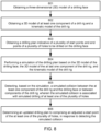
- FIG. 8 illustrates an example of a method for controlling a drill rig. The method may be performed by drilling controller 114 or drill rig 100, for example based on program code 706, when executed by drilling control device 202 or drill rig 100.
- the method may comprise obtaining a three-dimensional (3D) model of a drilling face.
- the method may comprise obtaining a 3D model of at least one component of a drill rig and a kinematic model of the drill rig.
- the method may comprise obtaining a drilling plan indicative of a plurality of start points and end points of a plurality of holes to be drilled on the drilling face
- the method may comprise performing a simulation of the drilling plan based on the 3D model of the drilling face, the 3D model of the at last one component of the drill rig, and the kinematic model of the drill rig.
- the method may comprise detecting, based on the simulation, a simulated collision between the at least one component of the drill rig and the drilling face or between components of the drill rig, wherein the simulated collision is associated with simulated drilling of at least one of the plurality of holes.
- the method may comprise determining an updated drilling plan comprising an adjusted a start point of the at least one of the plurality of holes, in response to detecting the simulated collision.
- Example embodiments of the present disclosure enable simulation of a drilling plan to be performed on the spot (e.g. at the tunnel), even before drilling a single hole.
- drilling controller 114 may identify any non-drillable holes in the drilling plan before initiating the drilling.
- Drill rig 100 may be moved to reach the holes or other actions may be taken, such as for example updating the start and/or end points of the holes. Not being able to reach a planned hole may be caused by an obstacle (e.g. a rock), by limitations on boom kinematics, or otherwise impossible positions of component(s) of drill rig 100. Such situations may be detected by simulations and avoided.
- the drilling plan may be updated for improving drillability, without significantly affecting the blast result designed/verified in advance by blast modelling tools.
- Efficiency of drilling may be improved, because expected problems with drilling may be proactively avoided before they occur. For example, even severe underbreak in the tunnel walls may not interrupt the drilling procedure and thereby drilling/blasting of the tunnel may progress more rapidly, because the underbreak may be considered when updating the drilling plan.
- the underbreak may be for example blasted separately in the same detonation if needed.
- subjects may be referred to as 'first' or 'second' subjects, this does not necessarily indicate any order or importance of the subjects. Instead, such attributes may be used solely for the purpose of making a difference between subj ects.
Landscapes
- Life Sciences & Earth Sciences (AREA)
- Engineering & Computer Science (AREA)
- Geology (AREA)
- Mining & Mineral Resources (AREA)
- Physics & Mathematics (AREA)
- Environmental & Geological Engineering (AREA)
- Fluid Mechanics (AREA)
- General Life Sciences & Earth Sciences (AREA)
- Geochemistry & Mineralogy (AREA)
- Earth Drilling (AREA)
- Management, Administration, Business Operations System, And Electronic Commerce (AREA)
Abstract
Description
- Various example embodiments generally relate to the field of drilling. Some example embodiments relate to updating a drilling plan based on 3D models of a drilling face and a drill rig.
- Drill rigs may be used for drilling holes in a drilling surface such as for example a rock face. For example, an underground drill rig may be configured to drill holes for explosives in mining applications. A surface drill rig may be configured for the same purpose at terrestrial environment. In such applications it may be desired to carefully plan locations of the holes such that the intended result is achieved by applying the explosives. Drill rigs may be equipped with one or more booms to enable holes to be drilled in the planned locations.
- This summary is provided to introduce a selection of concepts in a simplified form that are further described below in the detailed description. This summary is not intended to identify key features or essential features of the claimed subject matter, nor is it intended to be used to limit the scope of the claimed subject matter.
- According to a first aspect, a drilling control apparatus is disclosed. The drilling control apparatus may comprise: at least one processor; and at least one memory including computer program code, the at least one memory and the computer program code configured to, with the at least one processor, cause the apparatus at least to: obtain a three-dimensional (3D) model of a drilling face; obtain a 3D model of at least one component of a drill rig and a kinematic model of the drill rig; obtain a drilling plan indicative of a plurality of start points and end points of a plurality of holes to be drilled on the drilling face; perform a simulation of the drilling plan based on the 3D model of the drilling face, the 3D model of the at last one component of the drill rig, and the kinematic model of the drill rig; detect, based on the simulation, a simulated collision between the at least one component of the drill rig and the drilling face or between components of the drill rig, wherein the simulated collision is associated with simulated drilling of at least one of the plurality of holes; and determine an updated drilling plan comprising an adjusted start point of the at least one of the plurality of holes, in response to detecting the simulated collision.
- According to an example embodiment of the first aspect, the computer program code may be configured to, with the at least one processor, cause the apparatus to: maintain, in the updated drilling plan, an end point of the at least one of the plurality of holes, wherein the end point of the at least one of the plurality of holes was included in the drilling plan, adjust the end point of the at least one of the plurality of holes towards the adjusted start point of the at least one of the plurality of holes, or adjust the end point of the at least one of the plurality of holes towards the adjusted start point such that a distance between the adjusted start point and the end point is substantially equal to a distance between the start point and the end point of the at least one of the plurality of holes.
- According to an example embodiment of the first aspect, the computer program code may be configured to, with the at least one processor, cause the apparatus to: determine, based on the simulation, a location of a drilling unit of the drill rig, wherein the location of the drilling unit is associated with the simulated collision; determine a position for the drilling unit to reach the end point of the at least one of the plurality of holes from the determined location of the drilling unit; and adjust the start point of the at least one of the plurality of holes based on the determined position.
- According to an example embodiment of the first aspect, the computer program code may be configured to, with the at least one processor, cause the apparatus to: determine at least one candidate start point for the at least one of the plurality of holes; perform, based on the 3D model of the drilling face, the 3D model of the at last one component of the drill rig, and the kinematic model of the drill rig, a second simulation of drilling the at least one of the plurality of holes with the at least one candidate start point; and adjust the start point of the at least one of the plurality of holes based on the second simulation such that no simulated collision occurs between the at least one component of the drill rig and the drilling face or between the components of the drill rig.
- According to an example embodiment of the first aspect, the computer program code may be configured to, with the at least one processor, cause the apparatus to: adjust, based on the 3D model of the drilling face, the 3D model of the at least one component of the drill rig, and the kinematic model of the drill rig, the start point of the at least one of the plurality of holes such that no simulated collision occurs between the at least one component of the drill rig and the drilling face or between the components of the drill rig.
- According to an example embodiment of the first aspect, the computer program code may be configured to, with the at least one processor, cause the apparatus to: perform a mapping between the plurality of start points and end points and the 3D model of the drilling face.
- According to an example embodiment of the first aspect, the at least one component of the drill rig comprises at least one of the following: a first boom, a second boom, a first drilling unit coupled to the first boom, a second drilling unit coupled to the second boom, at least one boom part of the first boom, or at least one boom part of the second boom.
- According to an example embodiment of the first aspect, the computer program code may be configured to, with the at least one processor, cause the apparatus to: scan the drilling face to obtain the 3D model of the drilling face.
- According to an example embodiment of the first aspect, the computer program code may be configured to, with the at least one processor, cause the apparatus to: scan the drilling face, in response to detecting the drill rig to reach a planned drilling position.
- According to an example embodiment of the first aspect, the computer program code may be configured to, with the at least one processor, cause the apparatus to: initiate drilling of the plurality of holes based on the updated drilling plan.
- According to an example embodiment of the first aspect, the apparatus comprises the drill rig.
- According to an example embodiment of the first aspect, the computer program code may be configured to, with the at least one processor, cause the apparatus to: receive the 3D model of the drilling face from the drill rig to obtain the 3D model of the drilling face; and transmit the updated drilling plan to the drill rig.
- According to an example embodiment of the first aspect, the apparatus comprises a drilling control device, wherein the drilling control device is external to the drill rig.
- According to a second aspect, a method for controlling a drill rig is disclosed. The method may comprise: obtaining a three-dimensional (3D) model of a drilling face; obtaining a 3D model of at least one component of a drill rig and a kinematic model of the drill rig; obtain a drilling plan indicative of a plurality of start points and end points of a plurality of holes to be drilled on the drilling face; performing a simulation of the drilling plan based on the 3D model of the drilling face, the 3D model of the at last one component of the drill rig, and the kinematic model of the drill rig; detecting, based on the simulation, a simulated collision between the at least one component of the drill rig and the drilling face or between components of the drill rig, wherein the simulated collision is associated with simulated drilling of at least one of the plurality of holes; and determining an updated drilling plan comprising an adjusted start point of the at least one of the plurality of holes, in response to detecting the simulated collision.
- According to an example embodiment of the second aspect, the method may comprise: maintaining, in the updated drilling plan, an end point of the at least one of the plurality of holes, wherein the end point of the at least one of the plurality of holes was included in the drilling plan, adjusting the end point of the at least one of the plurality of holes towards the adjusted start point of the at least one of the plurality of holes, or adjusting the end point of the at least one of the plurality of holes towards the adjusted start point such that a distance between the adjusted start point and the end point is substantially equal to a distance between the start point and the end point of the at least one of the plurality of holes.
- According to an example embodiment of the second aspect, the method may comprise: determining, based on the simulation, a location of a drilling unit of the drill rig, wherein the location of the drilling unit is associated with the simulated collision; determine a position for the drilling unit to reach the end point of the at least one of the plurality of holes from the determined location of the drilling unit; and adjust the start point of the at least one of the plurality of holes based on the determined position.
- According to an example embodiment of the second aspect, the method may comprise: determining at least one candidate start point for the at least one of the plurality of holes; performing, based on the 3D model of the drilling face, the 3D model of the at last one component of the drill rig, and the kinematic model of the drill rig, a second simulation of drilling the at least one of the plurality of holes with the at least one candidate start point; and adjusting the start point of the at least one of the plurality of holes based on the second simulation such that no simulated collision occurs between the at least one component of the drill rig and the drilling face or between the components of the drill rig.
- According to an example embodiment of the second aspect, the method may comprise: adjusting, based on the 3D model of the drilling face, the 3D model of the at least one component of the drill rig, and the kinematic model of the drill rig, the start point of the at least one of the plurality of holes such that no simulated collision occurs between the at least one component of the drill rig and the drilling face or between the components of the drill rig.
- According to an example embodiment of the second aspect, the method may comprise: perform a mapping between the plurality of start points and end points and the 3D model of the drilling face.
- According to an example embodiment of the second aspect, the at least one component of the drill rig comprises at least one of the following: a first boom, a second boom, a first drilling unit coupled to the first boom, a second drilling unit coupled to the second boom, at least one boom part of the first boom, or at least one boom part of the second boom.
- According to an example embodiment of the second aspect, the method may comprise: scanning the drilling face to obtain the 3D model of the drilling face.
- According to an example embodiment of the second aspect, the method may comprise: scanning the drilling face, in response to detecting the drill rig to reach a planned drilling position.
- According to an example embodiment of the second aspect, the method may comprise: initiating drilling of the plurality of holes based on the updated drilling plan.
- According to an example embodiment of the second aspect, the method may be performed by the drill rig.
- According to an example embodiment of the second aspect, the method may comprise: receiving the 3D model of the drilling face from the drill rig to obtain the 3D model of the drilling face; and transmitting the updated drilling plan to the drill rig.
- According to an example embodiment of the second aspect, the method may be performed by a drilling control device, wherein the drilling control device is external to the drill rig.
- According to a third aspect, an apparatus is disclosed. The apparatus may comprise means for performing a method according to the second aspect, or any example embodiment thereof.
- According to a fourth aspect, a computer program or a computer program product is disclosed. The computer program or computer program product may comprise instructions, which when executed by an apparatus, cause the apparatus perform a method according to the second aspect, or any example embodiment thereof.
- According to a seventh aspect, a (non-transitory) computer readable medium is disclosed. The (non-transitory) computer readable medium may comprise program code that, when executed by an apparatus, cause the apparatus to perform a method according to the second aspect, or any example thereof.
- According to some aspects, there is provided the subject matter of the independent claims. Some further aspects are defined in the dependent claims. Many of the attendant features will be more readily appreciated as they become better understood by reference to the following description considered in connection with the accompanying drawings.
- The accompanying drawings, which are included to provide a further understanding of the example embodiments and constitute a part of this specification, illustrate example embodiments and, together with the description, help to explain the example embodiments. In the drawings:
-
FIG. 1 illustrates an example of a drill rig comprising a drilling controller; -
FIG. 2 illustrates an example of a drill rig communicatively coupled to a remote drilling controller; -
FIG. 3 illustrates an example of a drilling unit; -
FIG. 4 illustrates an example of a flow chart for determining an updated drilling plan; -
FIG. 5 illustrates an example of a simulated collision and an update of a start point of a hole; -
FIG. 6 illustrates an example of weighted control of at least one component of a drill rig; -
FIG. 7 illustrates an example of an apparatus configured to practise one or more example embodiments; and -
FIG. 8 illustrates an example of a method for controlling a drill rig. - Like references are used to designate like parts in the accompanying drawings.
- Reference will now be made to embodiments, examples of which are illustrated in the accompanying drawings. The description provided below in connection with the appended drawings is intended as a description of the present examples and is not intended to represent the only forms in which the present example may be constructed or utilized. The description sets forth the functions of the example and the sequence of steps for constructing and operating the example. However, the same or equivalent functions and sequences may be accomplished by different examples.
- Drill rigs may be operated based on a drilling plan to achieve the desired result, for example, to extend a tunnel by applying explosives at the drilled holes. The drilling plan may comprise start point(s) and end point(s) for one or a plurality of holes. A human operator may control the drill rig locally, e.g., sitting in the cabin of the drill rig, or via remote control. The operator may monitor and manually control boom(s) of the drill rig in order to avoid collisions between the boom(s) and the drilling surface (e.g. walls of the tunnel) or between the booms themselves. If a hole can not be drilled without a collision, for example, if the hole is not reachable, the operator may use his/her own judgement to manually position the boom at an adjusted position and to drill the hole from that position. However, in automatic drilling control systems it may be desired to handle such situations without human intervention. Furthermore, the adjusted positions determined by the operator may not be optimal for blasting the surface.
- Reactive boom collision monitoring/avoidance systems may be used to avoid collisions. However, in that case the decisions may be made reactively and therefore it may not be possible to predict whether holes of the drilling plan are reachable or drillable. A hole may be unreachable, for example, if the start point of the planned hole is inside the drilling face. In this case, the boom can not reach the target, regardless of whether collision avoidance is applied or not.
- Example embodiments of the present disclosure enable the drilling plan to be updated before drilling such that the desired result is still achieved when applying explosives at the drilled holes. Collisions may be therefore avoided and efficiency of the drilling procedure is improved.
- According to an example embodiment, an apparatus may obtain 3D models of a drilling face and component(s) of a drill rig, a kinematic model of the drill rig, and a drilling plan indicative of start and end points of a plurality of holes to be drilled on the drilling face. The apparatus may perform a simulation of the drilling plan based on the 3D models of the drilling face and the component(s) of the drill rig and the kinematic model of the drill rig, and detect, based on the simulation, a simulated collision between the component(s) of the drill rig and the drilling face or between the components of the drill rig, wherein the simulated collision is associated with simulated drilling of at least one of the plurality of holes. The apparatus may determine an updated drilling plan comprising an adjusted start point of the at least one of the plurality of holes, in response to detecting the simulated collision.
-
FIG. 1 illustrates an example of a drill rig comprising a drilling controller. Even thoughdrill rig 100 is illustrated as an underground drill rig, example embodiments of the present disclosure may be applied also to other type of drilling machines, such as for example surface drill rigs.Drill rig 100 may comprise a rock drilling rig.Drill rig 100 may be an automated drill rig, for example an automated underground drill rig or an automated surface drill rig. An automated mining vehicle, for example an automated underground drill rig, operating in an automatic mode may be configured to, for example, receive a task to be performed, perceive the environment of the mobile mining vehicle and autonomously perform the task while taking the environment into account. An automated mining vehicle operating in an automatic mode may be configured to operate independently but may be taken under external control at certain operation areas or conditions, such as during states of emergencies. Axis x represents the forward driving direction ofdrill rig 100. Axis z represents the vertical direction, in this example towards the roof of the tunnel.Drill rig 100 may comprise amovable carrier 110 and at least oneboom 120 connected tomovable carrier 110.Movable carrier 110 may comprise equipment for moving or stabilisingdrill rig 100, such as for example a motor, wheels, or stabilizer jacks. Even though twobooms 120 have been illustrated inFIG. 1 ,drill rig 100 may in general comprise one or a plurality (e.g. two, three, four,...) ofbooms 120. - A
drilling unit 130 may be coupled to a distal end portion ofboom 120. One example of a drilling unit is provided inFIG. 3 , but in general,drilling unit 130 may comprise a feeding system configured to keep a drill bit in contact withdrilling face 140 and to enable a drill rod to move along a feed beam during drilling. Boom(s) 120 may comprise a plurality of boom parts coupled to each other,movable carrier 110, and/ordrilling unit 130 by joint(s) 122. Controllable joints enabledrilling unit 130 to be placed at a desired position and orientation with respect todrilling face 140.Drilling face 140 may comprise at least part of the wall(s) of a tunnel, at least part of the roof of the tunnel, and/or at least part of the floor of the tunnel, for example near the end of the tunnel.Drilling face 140 may comprise an in-situ rock surface of the tunnel, for example near a drilling position ofdrill rig 100. The in-situ rock face may comprise the end of the tunnel and at least some of the walls, floor, and/or roof of the tunnel near the end of the tunnel. -
Drill rig 100 may comprise at least onesensor 112 for scanning environment ofdrill rig 100, for example,drilling face 140.Sensor 112 may include for example one or more of the following: a camera, a radio detection and ranging (radar) sensor, or a light detection and ranging (lidar) sensor.Sensor 112 may be configured to scandrilling face 140, for example to obtain a three-dimensional (3D) model ofdrilling face 140. A camera may be used to extract depth information ofdrilling face 140, for example by comparing two images taken at slightly different position (e.g., by two camera units). Alternatively,sensor 112 may comprise a time-of-flight (ToF) camera, which may be configured to determine a distance between the camera and points ofdrilling face 140 by measuring a round-trip time of an artificial light signal provided by a laser or a light-emitting diode (LED). A lidar sensor may be configured to determine a distance to different points ofdrilling face 140 by targetingdrilling face 140 with a laser and measuring the time for the reflected light to return to a receiver of the lidar sensor. A radar sensor may be configured to transmit electromagnetic energy towardsdrilling face 140 and to observe the echoes returned fromdrilling face 140 to determine distances to different points ofdrilling face 140. The 3D model of drilling face may be therefore fixed to, or known in relation to, a coordinate system ofdrill rig 100. -
Drill rig 100 may be configured to scandrilling face 140 using the at least onesensor 112, for example in response to detectingdrill rig 100 to reach a planned drilling position. The 3D model ofdrilling face 140 may be therefore represented with respect to the planned drilling position. This enables mapping between points of a coordinate frame that is stationary with respect todrill rig 100 and a coordinate frame ofdrilling face 140. The planned drilling position may be included in the drilling plan, which may be locally pre-configured at drill rig 100 (e.g., stored at a memory of drill rig 100) or received from another device (e.g., a remote drilling controller). The 3D model of drilling face may be provided as point-cloud data indicative of the positions ofdrilling face 140. -
Drill rig 100 may comprise adrilling controller 114.Drilling controller 114 may be communicatively coupled tosensor 112, for example to receive scanned sensor data fromsensor 112, or, to requestsensor 112 to initiate scanning ofdrilling face 140.Drilling controller 114 may be for example provided as a software application residing on a memory and being executable by a processor. An example of an apparatus suitable for implementingdrilling controller 114 is provided inFIG. 7 .Drilling controller 114 may comprise, or be communicatively coupled to, various functions, blocks, or applications for implementing functionality ofdrilling controller 114. For example,drilling controller 114 may comprise or be communicatively coupled to a data management server, which may be configured to store information of drilling plan(s), tunnel lines, point cloud or mesh presentations of tunnel lines or profiles, a mine map point cloud, or the like.Drilling controller 114 may comprise a drilling navigation application configured to control or enable a human user to control navigation ofdrill rig 100, for example to move it to the planned drilling position and to determine a relative location of the drilling plan in relation todrill rig 100 anddrilling face 140.Drilling controller 114 may comprise a drilling simulator configured to perform simulations of movement of component(s) of drill rig, for example based on a request from the drilling navigation application. Simulations may be used for example to obtain pre-knowledge of boom positions for a drilling round before real movement of booms atdrilling face 140. Simulation enables to determine a collision-free design for the drill plan. -
Drilling controller 114 may be configured to determine and/or maintain the drilling plan, a 3D model of at least one component of drill rig 100 (e.g., a 3D model of boom(s) 120 and/or a 3D model of drilling unit(s) 130). The 3D model of the at least one component ofdrill rig 100 may comprise 3D geometry data of the component(s), obtained for example from a computer aided design (CAD) model of the respective physical component(s).Drilling controller 114 may be also configured to determine and/or maintain a kinematic model ofdrill rig 100. The kinematic model may comprise information on dimensions of boom(s) 120, or parts thereof, characteristics of joint(s) 122 (e.g. their degrees of freedom), constraints between moving parts ofdrill rig 100, or the like. The kinematic model may thus enable modelling movement of the component(s) ofdrill rig 100, for example boom(s) 120 and/or associated drilling unit(s) 130. The 3D model(s) of the at least one component may be provided as point cloud data indicative of the surface of the at least one component. Point cloud data may comprise a plurality of data points representing, for example, distances betweendrill rig 100 and objects in the environment ofdrill rig 100 at a particular time instance. An individual point included in a point cloud may be presented by, for example, X and Y coordinates, or X, Y and Z coordinates with respect to a particular coordinate frame. - Alternatively,
drilling controller 114 may be external to drillrig 100, for example at an externaldrilling control device 202, as illustrated inFIG. 2 .Drilling control device 202 may be for example a server located remote fromdrill rig 100, for example outside the tunnel. Functionality ofdrilling controller 114 may be also distributed betweendrill rig 100, for example a local drilling controller ofdrill rig 100, and externaldrilling control device 202. Information may be exchanged betweendrilling controller 114 anddrill rig 100 over a communication interface including any suitable wireless or wired connection. Examples of suitable communication interfaces are described with reference toFIG. 7 .Drilling controller 114 may be configured to determine and/or maintain the drilling plan. The 3D and kinematic models ofdrill rig 100 may be locally stored atdrilling controller 114, for example based on pre-configuration of the models. Alternatively,drilling controller 114 may be configured to receive one or more of the models fromdrill rig 100 or the data management server.Drilling controller 114 may also be configured to receive, for example fromdrill rig 100, the scanned sensor data ofsensor 112, whichdrilling controller 114 may be configured to use for generating a 3D model ofdrilling face 140. Alternatively,drilling controller 114 may be configured to obtain the 3D model by receiving a 3D model ofdrilling face 140 generated bydrill rig 100 based on the scanned sensor data. Example embodiments of the present disclosure may be thus implemented locally atdrill rig 100 and/or at a remote drilling control system. - Referring back to
FIG. 1 , the drilling plan may comprise one or a plurality ofholes 150 with respective start points (sn ) and end points (en ). The start and end points of the holes may be represented in a reference coordinate frame used for planning the drilling. Using the location ofdrill rig 100 with respect to the reference coordinate frame,drilling controller 114 may be configured to map the start and end points of theholes 150 to the 3D model ofdrilling face 140 obtained based the scanning ofdrilling face 140 bydrill rig 100. Alternatively,drilling controller 114 may be configured to map the scanned 3D model ofdrilling face 140 to the coordinate system used to present the start and end points of theholes 150. In general,drilling controller 114 may be configured to perform a mapping between start and end points and the 3D model ofdrilling face 140. This helps to simulate of the drilling plan at the 3D model ofdrilling face 140. It is however noted that synchronization between the reference coordinate frame and the coordinate frame ofdrill rig 100 may be performed in any suitable manner. - Two examples of non-drillable holes are provided in
FIG. 1 .Hole 151 can not be drilled, because its start point (s 1) is below the ground level of the tunnel. On the other hand,hole 152 can not be drilled due to bump 142 located at the bottom surface of the tunnel, becausebump 142 preventsdrilling unit 130 from reaching the desired drilling position. Such situations may be however detected by simulations using the 3D model ofdrilling face 140, the 3D model of component(s) ofdrill rig 100, and the kinematic model ofdrill rig 100. Start points of these holes may be then adjusted to enable drilling to the original end point, as will be further described below. Sincedrilling controller 114 may be located atdrill rig 100 or external to drill rig, the simulation may be performed as an onboard simulation atdrill rig 100 or as a remote simulation at externaldrilling control device 202 comprisingdrilling controller 114. -
FIG. 3 illustrates an example of a drilling unit.Drilling unit 130 may comprise afeed beam 131 and arock drilling machine 132 supported on it. Therock drilling machine 132 may comprise a shank at a front end of therock drilling machine 132 for connecting a tool, such as forexample drill rod 133 comprising, or configured to be coupled to,drill bit 134. Further,drilling unit 130 may comprise one or morerod handling devices 135, such as for example a tool hold device, a tool changing apparatus or manipulator, and/or a tool magazine or storage. In addition to this, one or moreadditional devices 136 may be supported to thefeed beam 131. The 3D model of the at least one component ofdrill rig 100 may comprise 3D models of any of the above described components ofdrilling unit 130. It is however noted that a 3D model of a component ofdrill rig 100 need not be an accurate 3D model of the component. For example, approximate 3D model(s) may be used to represent approximate dimensions of the component(s) for the purpose of simulating collisions. This may reduce computational complexity, while still providing sufficient accuracy. -
FIG. 4 illustrates an example of a flow chart for determining an updated drilling plan. Some operations of the flow chart may be performed bydrilling controller 114, which may be located atdrill rig 100 or external to drillrig 100, for example at externaldrilling control device 202. Some of the operations, such as scanning drilling face or the drilling itself, may be performed bydrill rig 100. - At
operation 401,drill rig 100 may be configured to scandrilling face 140, for example withsensor 112.Drill rig 100 may be configured to generate a 3D model ofdrilling face 140 based on sensor data obtained by scanningdrilling face 140. The3D model 402 ofdrilling face 140 may be provided todrilling controller 114, which may be configured to store the model at a memory. Alternatively,drilling controller 114 may be configured to generate the 3D model ofdrilling face 140 based on sensor data provided bysensor 112.Drilling controller 114 may be configured to obtain a3D model 403 of at least one component ofdrill rig 100, including for example 3D model(s) ofboom 120 and/ordrilling unit 130.Drilling controller 114 may be configured to obtainkinematic model 404 ofdrill rig 100 or part(s)/component(s) thereof.Drilling controller 114 may be configured to obtaindrilling plan 405.3D model 403,kinematic model 404, and/ordrilling plan 405 may be retrieved from memory ofdrilling controller 114 or received from another device, for example from the data management server. As described above,drilling plan 405 may be indicative of start points (sn ) and end points (en ) ofholes 150 planned to be drilled ondrilling face 140. - At
operation 406,drilling controller 114 may be configured to initiate analysis of a next hole of the drilling plan. - At
operation 407,drilling controller 114 may be configured to determine whether the analysed hole is drillable.Drilling controller 114 may be configured to perform simulation of the analysed hole ofdrilling plan 406. The simulation may be based on the3D model 402 ofdrilling face 3D model 403 of the at least one component ofdrill rig 100, andkinematic model 404 ofdrill rig 100. Simulation ofdrilling plan 405 may include determining whether a simulated collision happens between component(s) of drill rig 100 (e.g. drilling unit 130,boom 120, or part(s) thereof) anddrilling face 140. Simulation ofdrilling plan 405 may include determining whether a simulated collision happens between components ofdrill rig 100. A collision may comprise unintentional (physical) contact between a first object and a second object. The first object may comprise a first part ofdrill rig 100. The second object may comprise a second part ofdrill rig 100 or an object in the environment ofdrill rig 100.Drilling controller 114 be configured to detect a simulated collision for example between a first boom ofdrill rig 100 anddrilling face 140, a first boom and a second boom ofdrill rig 100, a first drilling unit (coupled to the first boom) anddrilling face 140, a first drilling unit (coupled to the first boom of drill rig 100) and a second drilling unit (coupled to the second boom of drill rig 100), the first drilling unit and the second boom (or a part thereof), or at least one boom part of the first or second boom anddrilling face 140. A simulated collision may be detected, if point cloud data of the component(s) ofdrill rig 100 and/ordrilling face 140 overlap whendrilling unit 130 is placed, or moved to, the desired drilling position.Drilling controller 114 may be configured to determine the desired position ofdrilling unit 130 based on the start and end points of the analysed hole. -
FIG. 5 illustrates an example of a simulated collision. Axis x represents again the forward driving direction ofdrill rig 100. Axis y represents the other horizontal axis, in this example towards the left wall of the tunnel with respect to the forward driving direction.Drilling controller 114 may be configured to simulate movement ofdrilling unit 130 from its initial position towards the left wall. At some point,drilling controller 114 may be configured to detect the point cloud data ofdrilling unit 130 and the point cloud data ofdrilling face 140 to overlap. Based on the detected collision,drilling controller 114 may be configured to determine a possible position (e.g. the closest possible position to drilling surface 140) fordrilling unit 130 for drilling the analysed hole. It is however noted that movement to the desired drilling position may be prevented by collision of component(s) other thandrilling unit 130. For example, a simulated collision may be detected betweenboom 120 and drilling face 140 (or another boom), even ifdrilling unit 130 would fit to the desired drilling position. - Determining whether the analysed hole is drillable may comprise determining a resulting
end point 502, when drilling from the determined possible position ofdrilling unit 130 and initiating drilling from the plannedstart point 501. If the resultingend point 502 is not the same as, or within a threshold distance from, theplanned end point 503,drilling controller 114 may be configured to determine the hole to be non-drillable. - Referring back to
FIG. 4 , ifdrilling controller 114 determines the hole not to be drillable (e.g., due to a simulated collision),drilling controller 114 may move back tooperation 406 to analyse a next hole ofdrilling plan 405. If the hole is drillable (e.g., no simulated collision detected),drilling controller 114 may move tooperation 408 to adjust the start point of the hole. - At
operation 408,drilling controller 114 may be configured to adjust the start point of the analysed hole.FIG. 5 also illustrates an update of a hole ofdrilling plan 405. To updatedrilling plan 405,drilling controller 114 may be configured to determine anadjusted start point 504 for the analysed hole. The adjusted start point may be determined such that drilling to theplanned end point 503 is enabled from the determined possible position ofdrilling unit 130. Theplanned end point 503 may be however maintained indrilling plan 405. Maintaining the end point helps to get a successful blast, resulting in, at least approximately, the desired profile of the tunnel. It might be however possible to always maintain the end point, for example if thedrill bit 134 would not reach theplanned end point 503 when starting drilling from the adjustedstart point 504.Drilling controller 114 may therefore be configured to adjust theplanned end point 503 towards the adjustedstart point 504, for example based on length ofdrill rod 133 or in general the available drilling depth ofdrilling unit 130.Drilling controller 114 may alternatively be configured to adjust theplanned end point 503 towards the adjustedstart point 504 such that the distance between theadjusted start point 504 and the adjusted end point is substantially equal to the distance between theplanned start point 501 and theplanned end point 503. This helps to get a successful blast and to keep the resulting tunnel profile at least close to the desired profile. - In one example,
drilling controller 114 may be configured to determine, based on the simulation, a location ofdrilling unit 130, where the location is associated with the simulated collision. The location may be the exact location of the simulated collision, or a location in proximity of the collision location. The location ofdrilling unit 130 may be represented in any suitable manner, for example by locations of two points ofdrilling unit 130, or a location of one point ofdrilling unit 130 associated with a pose, for example orientation with respect to one or more axes (e.g. yaw, pitch, roll). Based on the determined location, drillingcontroller 114 may be configured to determine a position (e.g., location and/or orientation) that enables to reach theplanned end point 503 from the determined location.Drilling controller 114 may then be configured to determine the adjustedstart point 504 of the analysed hole based on the determined rotation such that the adjustedstart point 504 lies between theplanned end point 503 and the drilling unit 130 (e.g. drill bit 134) whendrilling unit 130 is rotated according to the determined rotation. - This example may comprise manipulating the positioning setpoint, by
drilling controller 114, for example, to causedrill bit 134 to move to theplanned start point 501. One setpoint may represent a point within a trajectory for moving a component ofdrill rig 100, for example,drill bit 134, to a target position. A set of positioning setpoints may be defined between an initial position of the component and the target position to define the trajectory. The target position may be the plannedstart point 501. For example, a last set point may be the planned start point. A rotation setpoint may similarly represent of a point of the component, when rotating the component to a planned orientation.Drilling controller 114 may be configured to, for example, simulate movement ofboom 120 and/or other component(s) ofdrill rig 100 towards the start point of the analysed hole, for example with a predefined speed.Drilling controller 114 may be configured to determine a target position ofdrilling unit 130 based on the start point of the analysed hole.Drilling controller 114 may be configured to determine a target rotation as a function of the planned start and end points, using geometrical calculations.Drilling controller 114 may be configured to update the target position to be the current position ofdrilling unit 130, if a simulated collision is detected (e.g. based on a minimum threshold for the distance betweendrilling unit 130 and drilling face 140).Drilling controller 114 may be configured to update the target rotation such that it is determined as a function of the planned end point and the current position ofdrilling unit 130.Drilling controller 114 may be configured to manipulate final position target opposite to obstacle if the distance falls too low.Drilling controller 114 may be configured to split the point cloud and predefine correct yielding direction for each point cloud. For example, the point cloud may be split to a plurality of subsets, wherein each subset is associated with a different yielding direction away fromdrilling face 140, or in general, an obstacle. Drilling controller 104 may determine the yielding direction by the surface normal of the 3D model ofdrilling face 140 at the point of collision. For example, a first subset of the point could for which the closest portion ofdrilling face 140 is a first portion of the drilling face (e.g. the left wall with respect to the forward driving direction of drill rig 110), may be associated with a first yielding direction (e.g. to the right). A second subset for which the closest part of drilling face is a second portion of drilling face 140 (e.g. roof), may be associated with a second yielding direction (e.g. down), which may be different from the first yielding direction. Different yielding directions may be therefore associated with different subsets of the point cloud, for example the left wall, the right wall, the roof, the floor, or the end of the tunnel.Drilling controller 114 may determine the updated start point by moving the start point to the yielding direction associated with the location (in the point cloud data) of the simulated collision. This enables to speed up generation of the updated drilling plan, because the expected direction of adjusting the start point is readily available after detecting the simulated collision. -
FIG. 6 illustrates an example of weighted control of at least one component of a drill rig. Controlling (simulated) movement of the component(s) ofdrill rig 100, such as forexample boom 120 and/ordrilling unit 130, may be based on weighting of control signals of acollision avoidance system 602 configured to avoid collisions and apositioning system 604 configured to move the component(s) in order to reach the planned drilling position, for example such thatdrill rig 100 is enabled to reach both the start and end point of the associated hole. For example,positioning system 604 may be configured to cause an attractive force via virtual (simulated)valves 606 that causes component(s) ofdrill rig 100 to move towards an obstacle close to the planned drilling position, for example part ofdrilling face 140 or another component ofdrill rig 100.Collision avoidance system 602 may be configured to cause a rejective force viavirtual valves 606 that restricts or prevents movement of the component(s) ofdrill rig 100 to towards the obstacle. Hybrid positioning may be hence applied when the component(s) are in a rejection zone (e.g. within a threshold distance from the obstacle). A collision-free drilling position may be determined based on a stabilization point of the attractive and rejective forces. In simulations,virtual valves 606 may be configured to model real valves, for example by providing motion requests or position change requests for kinematic joint(s) in desired directions. A position setpoint may be obtained fromcollision avoidance system 602. A rotation setpoint may be obtained frompositioning system 604. The control signals ofcollision avoidance system 602 andpositioning system 604 may be weighted with multiplicative weights w 1 and w 2, respectively. Results of the multiplications may be summed to obtain a combined control signal forvirtual valves 606. In one example, w 2 = 1 - w 1. For example, w 1 = 0.8 and w 2 = 0.2. This provides a good balance between the attractive and rejective forces, thereby enabling smooth approach to a suitable position for drilling, while avoiding a collision. This approach may be also used when detecting "collisions" in the simulation environment. - In one example, a brute-force like approach may be used to adjust the start point of the analysed hole. In this approach,
drilling controller 114 may be configured to test different start points to find a start point that enables collision free drilling to theplanned end point 503.Drilling controller 114 may be configured to determine candidate start point(s), for example randomly selected point(s) around theplanned start point 501.Drilling controller 114 may then be configured to perform a second simulation, again based on the 3D model ofdrilling face 140, the 3D model of the component(s) of drill rig 100 (e.g. boom 120 and/or drilling unit 130), and the kinematic model ofdrill rig 100. This simulation may be performed for one of the candidate start points at a time to detect whether that candidate start point enables collision-free drilling of the analysed hole. - Various approaches may be used to perform the simulation over the different candidate start points. For example,
drilling controller 114 may be configured to iterate the simulation over the candidate start points starting from the point closest to theplanned start point 501 and continuing in an increasing order of distance to theplanned start point 501. Using this approach, drilling unit may be configured to determine the adjusted start point to be the first identified candidate start point that enables collision-free drilling. Alternatively,drilling controller 114 may be configured to iterate the simulation with the different candidate start points without considering their distance to theplanned start point 501. In this case,drilling controller 114 may be configured to continue iterating the candidate start points even if it finds a start point that enables collision-free drilling. The adjusted start point may be selected to be the candidate start point that is closest to the planned start point 105 and that enables collision-free drilling. The start point may be therefore adjusted such that no simulated collision occurs with the adjusted start point. In the example ofFIG. 4 , the adjusted point may bepoint 504. - In one example, the start point of the analysed hole may be adjusted based on analytically finding a point that enables collision-free drilling to the
planned end point 503. This analysis may include calculating, based on the 3D model ofdrilling face 140, the 3D model of the component(s) ofdrill rig 100, and the kinematic model ofdrill rig 100, a position fordrilling unit 130 that is sufficiently far fromdrilling face 140 and that is a possible position for the drilling unit considering the kinematic model. For example,drilling controller 114 may analytically determine the possible position ofdrilling unit 130 illustrated inFIG. 5 and determine the adjustedstart point 504 accordingly. - At
operation 409,drilling controller 114 may be configured to determine whether there are more holes to analyse, in other words whether it has already analysed the holes ofdrilling plan 405. If there are further holes to be analysed,drilling controller 114 may be configured to move back tooperation 406 to analyse a next planned whole. By iteratingoperations drilling plan 405,drilling controller 114 may be configured to determine an updated drilling plan, where a start point of at least one of the holes is adjusted, for example as described with reference tooperation 408.Drilling controller 114 may be configured to determine the updated drilling plan, in response to detecting at least one simulated collision. When updating the drilling plan,drilling controller 114 may update start point(s) of hole(s) that would cause a collision, while maintaining an identifier of the hole in the drilling plan. Alternatively,drilling controller 114 may be configured to delete or mark as invalid the hole(s) that would cause a collision and create a new hole having a different identifier, the adjusted start point, and the originally planned end point or the adjusted end point. Invalidating the original hole and replacing the original hole by another one may help to visualize the updates in the drilling plan, for example for documentation of the changes. - At
operation 410,drilling controller 114 may be configured to cause initiation of drilling. Ifdrilling controller 114 is located external to drillrig 100, as in the example ofFIG. 2 ,drilling controller 114 may be configured to causedrill rig 100 to initiate drilling by transmitting a request or a command to drillrig 100 to initiate drilling.Drilling controller 114 may be configured to transmit the updated drilling plan to drillrig 100, for example prior to, or along with, transmission of the request or command to initiate drilling.Drill rig 100 may be configured to initiate drilling, in response to receiving a command or a request for initiating drilling fromdrilling controller 114, regardless of whetherdrilling controller 114 is located atdrill rig 100 or external to drillrig 100. When drillingcontroller 114 is located external to drillrig 100,drill rig 100 may include a local drilling controller (not shown inFIG. 2 ) for controlling the component(s) ofdrill rig 100 in order to perform drilling based on, or according to, the updated drilling plan received from theexternal drilling controller 114. Initiating drilling after updating ofdrilling plan 405 may improve efficiency of the drilling procedure, because drilling does not need to be interrupted because of encountering non-drillable holes. -
FIG. 7 illustrates an example of an apparatus configured to practise one or more example embodiments.Apparatus 700 may be or comprise a drilling control apparatus, such as for example a server communicatively coupled todrill rig 100, a drilling control device located atdrill rig 100, externaldrilling control device 202,drilling controller 114,drill rig 100 itself, or in general any device or system configured to implement the functionality described herein. Althoughapparatus 700 is illustrated as a single device, it is appreciated that, wherever applicable, functions ofapparatus 700 may be distributed to a plurality of devices. -
Apparatus 700 may comprise at least oneprocessor 702. The at least oneprocessor 702 may comprise, for example, one or more of various processing devices, such as for example a co-processor, a microprocessor, a controller, a digital signal processor (DSP), a processing circuitry with or without an accompanying DSP, or various other processing devices including integrated circuits such as, for example, an application specific integrated circuit (ASIC), a field programmable gate array (FPGA), a microcontroller unit (MCU), a hardware accelerator, a special-purpose computer chip, or the like. -
Apparatus 700 may further comprise at least onememory 704. The at least onememory 704 may be configured to store, for example, computer program code or the like, for example operating system software and application software. Thememory 704 may comprise one or more volatile memory devices, one or more non-volatile memory devices, and/or a combination thereof. For example, the memory may be embodied as magnetic storage devices (such as hard disk drives, , etc.), optical magnetic storage devices, or semiconductor memories (such as mask ROM, PROM (programmable ROM), EPROM (erasable PROM), flash ROM, RAM (random access memory), etc.).Memory 704 is provided as an example of a (non-transitory) computer readable medium. The term "non-transitory," as used herein, is a limitation of the medium itself (i.e., tangible, not a signal) as opposed to a limitation on data storage persistency (e.g., RAM vs. ROM). The at least onememory 704 may be also embodied separate fromapparatus 700, for example as a computer readable (storage) medium, examples of which include memory sticks, compact discs (CD), or the like. - When
apparatus 700 is configured to implement some functionality, some component and/or components ofapparatus 700, such as for example the at least oneprocessor 702 and/or the at least onememory 704, may be configured to implement this functionality. Furthermore, when the at least oneprocessor 702 is configured to implement some functionality, this functionality may be implemented usingprogram code 706 comprised, for example, in the at least onememory 704. - The functionality described herein may be performed, at least in part, by one or more computer program product components such as software components. According to an example embodiment,
apparatus 700 comprises a processor or processor circuitry, such as for example a microcontroller, configured by theprogram code 706, when executed, to execute the embodiments of the operations and functionality described herein.Program code 706 is provided as an example of instructions which, when executed by the at least oneprocessor 702, cause performance ofapparatus 700. - For example,
drilling controller 114 may be at least partially implemented as program code configured to cause the apparatus to perform functionality ofdrilling controller 114. Similarly, transmission of data (e.g. sensor data, 3D or kinematic model(s), or the drilling plan) over an internal or external communication interface ofdrill rig 100 may be controlled by software. - Alternatively, or in addition, the functionality described herein can be performed, at least in part, by one or more hardware logic components. For example, and without limitation, illustrative types of hardware logic components that can be used include field-programmable gate arrays (FPGAs), application-specific integrated circuits (ASICs), application-specific standard products (ASSPs), system-on-a-chip systems (SOCs), complex programmable logic devices (CPLDs), graphics processing units (GPUs), neural processing unit (NPU), tensor processing unit (TPU), or the like.
-
Apparatus 700 may comprise acommunication interface 708 configured to enableapparatus 700 to transmit and/or receive information.Communication interface 708 may comprise an internal or external communication interface, such as for example a radio interface betweendrill rig 100 and externaldrilling control device 202.Apparatus 700 may further comprise other components and/or functions such as for example a user interface (not shown) comprising at least one input device and/or at least one output device. The input device may take various forms such a keyboard, a touch screen, or one or more embedded control buttons. The output device may for example comprise a display, a speaker, or the like. The user interface may enable a human user to monitor various operations, such as for example generation of the updated drilling plan, visualization of execution of the updated drilling plan, or the like. -
Apparatus 700 may be configured to perform or cause performance of any aspect of the method(s) described herein. Further, a computer program or a computer program product may comprise instructions for causing, when executed byapparatus 700,apparatus 700 to perform any aspect of the method(s) described herein. Further,apparatus 700 may comprise means for performing any aspect of the method(s) described herein. In one example, the means comprises the at least oneprocessor 702, the at least onememory 704 including program code 706 (instructions) configured to, when executed by the at least oneprocessor 702,cause apparatus 700 to perform the method(s). In general, computer program instructions may be executed on means providing generic processing functions. Such means may be embedded for example in a computer, a server, or the like. The method(s) may be thus computer-implemented, for example based algorithm(s) executable by the generic processing functions, an example of which is the at least oneprocessor 702.Apparatus 700 may comprise means for transmitting or receiving information, for example one or more wired of wireless (e.g. radio) transmitters or receivers, which may be coupled or be configured to be coupled to one or more antennas, or transmitter(s) or receiver(s) of a wired communication interface. -
FIG. 8 illustrates an example of a method for controlling a drill rig. The method may be performed bydrilling controller 114 ordrill rig 100, for example based onprogram code 706, when executed bydrilling control device 202 ordrill rig 100. - At 801, the method may comprise obtaining a three-dimensional (3D) model of a drilling face.
- At 802, the method may comprise obtaining a 3D model of at least one component of a drill rig and a kinematic model of the drill rig.
- At 803, the method may comprise obtaining a drilling plan indicative of a plurality of start points and end points of a plurality of holes to be drilled on the drilling face
- At 804, the method may comprise performing a simulation of the drilling plan based on the 3D model of the drilling face, the 3D model of the at last one component of the drill rig, and the kinematic model of the drill rig.
- At 805, the method may comprise detecting, based on the simulation, a simulated collision between the at least one component of the drill rig and the drilling face or between components of the drill rig, wherein the simulated collision is associated with simulated drilling of at least one of the plurality of holes.
- At 806, the method may comprise determining an updated drilling plan comprising an adjusted a start point of the at least one of the plurality of holes, in response to detecting the simulated collision.
- Various examples of the methods are explained above with regard to functionalities of
drilling controller 114,drilling control device 202, and/ordrill rig 100, and are therefore not repeated here. It should be understood that example embodiments described may be combined in different ways unless explicitly disallowed. - Example embodiments of the present disclosure, enable simulation of a drilling plan to be performed on the spot (e.g. at the tunnel), even before drilling a single hole. Based on simulation,
drilling controller 114 may identify any non-drillable holes in the drilling plan before initiating the drilling.Drill rig 100 may be moved to reach the holes or other actions may be taken, such as for example updating the start and/or end points of the holes. Not being able to reach a planned hole may be caused by an obstacle (e.g. a rock), by limitations on boom kinematics, or otherwise impossible positions of component(s) ofdrill rig 100. Such situations may be detected by simulations and avoided. The drilling plan may be updated for improving drillability, without significantly affecting the blast result designed/verified in advance by blast modelling tools. Efficiency of drilling may be improved, because expected problems with drilling may be proactively avoided before they occur. For example, even severe underbreak in the tunnel walls may not interrupt the drilling procedure and thereby drilling/blasting of the tunnel may progress more rapidly, because the underbreak may be considered when updating the drilling plan. The underbreak may be for example blasted separately in the same detonation if needed. - Although the subject matter has been described in language specific to structural features and/or acts, it is to be understood that the subject matter defined in the appended claims is not necessarily limited to the specific features or acts described above. Rather, the specific features and acts described above are disclosed as examples of implementing the claims and other equivalent features and acts are intended to be within the scope of the claims.
- It will be understood that the benefits and advantages described above may relate to one embodiment or may relate to several embodiments. The embodiments are not limited to those that solve any or all of the stated problems or those that have any or all of the stated benefits and advantages. It will further be understood that reference to 'an' item may refer to one or more of those items.
- The steps or operations of the methods described herein may be carried out in any suitable order, or simultaneously where appropriate. Additionally, individual blocks may be deleted from any of the methods without departing from the scope of the subject matter described herein. Aspects of any of the example embodiments described above may be combined with aspects of any of the other example embodiments described to form further example embodiments without losing the effect sought.
- The term 'comprising' is used herein to mean including the method, blocks, or elements identified, but that such blocks or elements do not comprise an exclusive list and a method or apparatus may contain additional blocks or elements.
- As used herein, "at least one of the following: <a list of two or more elements>" and "at least one of <a list of two or more elements>" and similar wording, where the list of two or more elements are joined by "and" or "or", mean at least any one of the elements, or at least any two or more of the elements, or at least all the elements. Term "or" may be understood to cover also a case where both of the items separated by "or" are included. Hence, "or" may be understood as an inclusive "or" rather than an exclusive "or".
- Although subjects may be referred to as 'first' or 'second' subjects, this does not necessarily indicate any order or importance of the subjects. Instead, such attributes may be used solely for the purpose of making a difference between subj ects.
- It will be understood that the above description is given by way of example only and that various modifications may be made by those skilled in the art. The above specification, examples and data provide a complete description of the structure and use of exemplary embodiments. Although various embodiments have been described above with a certain degree of particularity, or with reference to one or more individual embodiments, those skilled in the art could make numerous alterations to the disclosed embodiments without departing from scope of this specification.
Claims (15)
- A drilling control apparatus, comprising:at least one processor;and at least one memory including computer program code, the at least one memory and the computer program code configured to, with the at least one processor, cause the apparatus at least to:obtain a three-dimensional (3D) model of a drilling face;obtain a 3D model of at least one component of a drill rig and a kinematic model of the drill rig;obtain a drilling plan indicative of a plurality of start points and end points of a plurality of holes to be drilled on the drilling face;perform a simulation of the drilling plan based on the 3D model of the drilling face, the 3D model of the at last one component of the drill rig, and the kinematic model of the drill rig;detect, based on the simulation, a simulated collision between the at least one component of the drill rig and the drilling face or between components of the drill rig, wherein the simulated collision is associated with simulated drilling of at least one of the plurality of holes; anddetermine an updated drilling plan comprising an adjusted start point of the at least one of the plurality of holes, in response to detecting the simulated collision.
- The apparatus according to claim 1, wherein the computer program code is further configured to, with the at least one processor, cause the apparatus to:maintain, in the updated drilling plan, an end point of the at least one of the plurality of holes, wherein the end point of the at least one of the plurality of holes was included in the drilling plan,adjust the end point of the at least one of the plurality of holes towards the adjusted start point of the at least one of the plurality of holes, oradjust the end point of the at least one of the plurality of holes towards the adjusted start point such that a distance between the adjusted start point and the end point is substantially equal to a distance between the start point and the end point of the at least one of the plurality of holes.
- The apparatus according to claim 1 or 2, wherein the computer program code is further configured to, with the at least one processor, cause the apparatus to:determine, based on the simulation, a location of a drilling unit of the drill rig, wherein the location of the drilling unit is associated with the simulated collision;determine a position for the drilling unit to reach the end point of the at least one of the plurality of holes from the determined location of the drilling unit; andadjust the start point of the at least one of the plurality of holes based on the determined position.
- The apparatus according to claim 1 or 2, wherein the computer program code is further configured to, with the at least one processor, cause the apparatus to:determine at least one candidate start point for the at least one of the plurality of holes;perform, based on the 3D model of the drilling face, the 3D model of the at last one component of the drill rig, and the kinematic model of the drill rig, a second simulation of drilling the at least one of the plurality of holes with the at least one candidate start point; andadjust the start point of the at least one of the plurality of holes based on the second simulation such that no simulated collision occurs between the at least one component of the drill rig and the drilling face or between the components of the drill rig.
- The apparatus according to claim 1 or 2, wherein the computer program code is further configured to, with the at least one processor, cause the apparatus to:adjust, based on the 3D model of the drilling face, the 3D model of the at least one component of the drill rig, and the kinematic model of the drill rig, the start point of the at least one of the plurality of holes such that no simulated collision occurs between the at least one component of the drill rig and the drilling face or between the components of the drill rig.
- The apparatus according to any of claims 1 to 5, wherein the computer program code is further configured to, with the at least one processor, cause the apparatus to:perform a mapping between the plurality of start points and end points and the 3D model of the drilling face.
- The apparatus according to any of claims 1 to 6, wherein the at least one component of the drill rig comprises at least one of the following:a first boom,a second boom,a first drilling unit coupled to the first boom,a second drilling unit coupled to the second boom,at least one boom part of the first boom, orat least one boom part of the second boom.
- The apparatus according to any of claims 1 to 7, wherein the computer program code is further configured to, with the at least one processor, cause the apparatus to:scan the drilling face to obtain the 3D model of the drilling face.
- The apparatus according to claim 8, wherein the computer program code is further configured to, with the at least one processor, cause the apparatus to:scan the drilling face, in response to detecting the drill rig to reach a planned drilling position.
- The apparatus according to any of claims 1 to 9, wherein the computer program code is further configured to, with the at least one processor, cause the apparatus to:initiate drilling of the plurality of holes based on the updated drilling plan.
- The apparatus according to any of claims 1 to 10, wherein the apparatus comprises the drill rig.
- The apparatus according to any of claims 1 to 7, wherein the computer program code is further configured to, with the at least one processor, cause the apparatus to:receive the 3D model of the drilling face from the drill rig to obtain the 3D model of the drilling face; andtransmit the updated drilling plan to the drill rig.
- The apparatus according to claim 12, wherein the apparatus comprises a drilling control device, wherein the drilling control device is external to the drill rig.
- A method, comprising: :obtaining a three-dimensional (3D) model of a drilling face;obtaining a 3D model of at least one component of a drill rig and a kinematic model of the drill rig;obtaining a drilling plan indicative of a plurality of start points and end points of a plurality of holes to be drilled on the drilling face;performing a simulation of the drilling plan based on the 3D model of the drilling face, the 3D model of the at last one component of the drill rig, and the kinematic model of the drill rig;detecting, based on the simulation, a simulated collision between the at least one component of the drill rig and the drilling face or between components of the drill rig, wherein the simulated collision is associated with simulated drilling of at least one of the plurality of holes; anddetermining an updated drilling plan comprising an adjusted start point of the at least one of the plurality of holes, in response to detecting the simulated collision.
- A computer program comprising instructions which, when executed by an apparatus, cause the apparatus at least to:obtain a three-dimensional (3D) model of a drilling face;obtain a 3D model of at least one component of a drill rig and a kinematic model of the drill rig;obtain a drilling plan indicative of a plurality of start points and end points of a plurality of holes to be drilled on the drilling face;perform a simulation of the drilling plan based on the 3D model of the drilling face, the 3D model of the at last one component of the drill rig, and the kinematic model of the drill rig;detect, based on the simulation, a simulated collision between the at least one component of the drill rig and the drilling face or between components of the drill rig, wherein the simulated collision is associated with simulated drilling of at least one of the plurality of holes; anddetermine an updated drilling plan comprising an adjusted start point of the at least one of the plurality of holes, in response to detecting the simulated collision.
Priority Applications (7)
| Application Number | Priority Date | Filing Date | Title |
|---|---|---|---|
| EP22196730.0A EP4343105A1 (en) | 2022-09-20 | 2022-09-20 | Determination of an updated drilling plan |
| US19/112,811 US20260085583A1 (en) | 2022-09-20 | 2023-09-20 | Determination of an updated drilling plan |
| AU2023347016A AU2023347016A1 (en) | 2022-09-20 | 2023-09-20 | Determination of an updated drilling plan |
| PCT/EP2023/075985 WO2024061995A1 (en) | 2022-09-20 | 2023-09-20 | Determination of an updated drilling plan |
| CA3266179A CA3266179A1 (en) | 2022-09-20 | 2023-09-20 | Determination of an updated drilling plan |
| CN202380066552.XA CN119836512A (en) | 2022-09-20 | 2023-09-20 | Determination of updated drilling plans |
| CL2025000697A CL2025000697A1 (en) | 2022-09-20 | 2025-03-12 | Determining an updated drilling plan. |
Applications Claiming Priority (1)
| Application Number | Priority Date | Filing Date | Title |
|---|---|---|---|
| EP22196730.0A EP4343105A1 (en) | 2022-09-20 | 2022-09-20 | Determination of an updated drilling plan |
Publications (1)
| Publication Number | Publication Date |
|---|---|
| EP4343105A1 true EP4343105A1 (en) | 2024-03-27 |
Family
ID=83398199
Family Applications (1)
| Application Number | Title | Priority Date | Filing Date |
|---|---|---|---|
| EP22196730.0A Pending EP4343105A1 (en) | 2022-09-20 | 2022-09-20 | Determination of an updated drilling plan |
Country Status (7)
| Country | Link |
|---|---|
| US (1) | US20260085583A1 (en) |
| EP (1) | EP4343105A1 (en) |
| CN (1) | CN119836512A (en) |
| AU (1) | AU2023347016A1 (en) |
| CA (1) | CA3266179A1 (en) |
| CL (1) | CL2025000697A1 (en) |
| WO (1) | WO2024061995A1 (en) |
Cited By (1)
| Publication number | Priority date | Publication date | Assignee | Title |
|---|---|---|---|---|
| EP4671488A1 (en) * | 2024-06-25 | 2025-12-31 | Sandvik Mining and Construction Oy | CONTROL OF A DRILLING UNIT BASED ON THE DISTANCE TO THE ROCK SURFACE |
Citations (3)
| Publication number | Priority date | Publication date | Assignee | Title |
|---|---|---|---|---|
| EP3385494A1 (en) * | 2017-04-05 | 2018-10-10 | Sandvik Mining and Construction Oy | Apparatus and method for controlling boom of mine vehicle |
| CN112861361A (en) * | 2021-02-20 | 2021-05-28 | 中国铁建重工集团股份有限公司 | Working space simulation method based on drill jumbo |
| US20220162911A1 (en) * | 2019-03-19 | 2022-05-26 | Sandvik Mining And Construction Oy | Mine vehicle boom positioning control |
-
2022
- 2022-09-20 EP EP22196730.0A patent/EP4343105A1/en active Pending
-
2023
- 2023-09-20 CA CA3266179A patent/CA3266179A1/en active Pending
- 2023-09-20 AU AU2023347016A patent/AU2023347016A1/en active Pending
- 2023-09-20 US US19/112,811 patent/US20260085583A1/en active Pending
- 2023-09-20 CN CN202380066552.XA patent/CN119836512A/en active Pending
- 2023-09-20 WO PCT/EP2023/075985 patent/WO2024061995A1/en not_active Ceased
-
2025
- 2025-03-12 CL CL2025000697A patent/CL2025000697A1/en unknown
Patent Citations (3)
| Publication number | Priority date | Publication date | Assignee | Title |
|---|---|---|---|---|
| EP3385494A1 (en) * | 2017-04-05 | 2018-10-10 | Sandvik Mining and Construction Oy | Apparatus and method for controlling boom of mine vehicle |
| US20220162911A1 (en) * | 2019-03-19 | 2022-05-26 | Sandvik Mining And Construction Oy | Mine vehicle boom positioning control |
| CN112861361A (en) * | 2021-02-20 | 2021-05-28 | 中国铁建重工集团股份有限公司 | Working space simulation method based on drill jumbo |
Non-Patent Citations (2)
| Title |
|---|
| SANDVIK: "iSURE 8.1 SOFTWARE", 12 March 2021 (2021-03-12), pages 1 - 22, XP055889470, Retrieved from the Internet <URL:https://www.rocktechnology.sandvik/en/products/underground-drill-rigs-and-bolters/underground-equipment-support/isure/> [retrieved on 20220209] * |
| T. KIVELA ET AL: "Redundant Robotic Manipulator Path Planning for Real-Time Obstacle and Self-Collision Avoidance", ROBOTICS AND MECHATRONICS : PROCEEDINGS O THE 6TH IFTOMM INTERNATIONAL SYMPOSIUM ON ROBOTICS AND MECHATRONICS (ISRM 2019) SERIES TITLE: MECHANISMS AND MACHINE SCIENCE ISSN 2211-0984, vol. 49, 1 January 2017 (2017-01-01), CH, pages 208 - 216, XP055412346, ISBN: 978-94-007-2726-7 * |
Cited By (2)
| Publication number | Priority date | Publication date | Assignee | Title |
|---|---|---|---|---|
| EP4671488A1 (en) * | 2024-06-25 | 2025-12-31 | Sandvik Mining and Construction Oy | CONTROL OF A DRILLING UNIT BASED ON THE DISTANCE TO THE ROCK SURFACE |
| WO2026003065A1 (en) * | 2024-06-25 | 2026-01-02 | Sandvik Mining And Construction Oy | Controlling drilling unit based on distance to rock surface |
Also Published As
| Publication number | Publication date |
|---|---|
| CL2025000697A1 (en) | 2025-08-29 |
| WO2024061995A1 (en) | 2024-03-28 |
| AU2023347016A1 (en) | 2025-03-27 |
| CN119836512A (en) | 2025-04-15 |
| US20260085583A1 (en) | 2026-03-26 |
| CA3266179A1 (en) | 2024-03-28 |
Similar Documents
| Publication | Publication Date | Title |
|---|---|---|
| US12146407B2 (en) | Mine vehicle boom positioning control | |
| CN105917067B (en) | Mine vehicle and the method for initializing mining activity task | |
| AU2013200273B2 (en) | Apparatus and method for drive path search | |
| EP3094806B1 (en) | Mine vehicle and method of initiating mine work task | |
| US20260085583A1 (en) | Determination of an updated drilling plan | |
| US20240127372A1 (en) | Construction management system, data processing device, and construction management method | |
| CN114391060A (en) | Positioning of mobile equipment in an underground worksite | |
| CN118829955A (en) | Coordinate transformation for mining vehicle positioning | |
| EP4534797A1 (en) | Determining position for a bolt of a bolt fan | |
| EP3757299B1 (en) | Apparatus for generating environment data around construction equipment and construction equipment including the same | |
| US12110793B2 (en) | Automated system for face drill machines | |
| JP7578529B2 (en) | Construction management system, data processing device, and construction management method | |
| EP4403745A1 (en) | Meshing plan for controlling mesh installation | |
| EP4403743A1 (en) | Controlling mesh installation | |
| EP4403744A1 (en) | Controlling mesh installation | |
| EP4407140A1 (en) | Controlling replacement of a mining tool of a mining vehicle | |
| WO2026003065A1 (en) | Controlling drilling unit based on distance to rock surface | |
| EP4556677A1 (en) | Drill rig navigation correction | |
| JP2026515926A (en) | Updating mesh planning based on actual surface models of rock surfaces | |
| JP2026515927A (en) | Control of mesh placement based on mesh deformation parameters | |
| EP4575098A1 (en) | Determining a bucket fill parameter value for a loader |
Legal Events
| Date | Code | Title | Description |
|---|---|---|---|
| PUAI | Public reference made under article 153(3) epc to a published international application that has entered the european phase |
Free format text: ORIGINAL CODE: 0009012 |
|
| STAA | Information on the status of an ep patent application or granted ep patent |
Free format text: STATUS: THE APPLICATION HAS BEEN PUBLISHED |
|
| AK | Designated contracting states |
Kind code of ref document: A1 Designated state(s): AL AT BE BG CH CY CZ DE DK EE ES FI FR GB GR HR HU IE IS IT LI LT LU LV MC MK MT NL NO PL PT RO RS SE SI SK SM TR |
|
| STAA | Information on the status of an ep patent application or granted ep patent |
Free format text: STATUS: REQUEST FOR EXAMINATION WAS MADE |
|
| 17P | Request for examination filed |
Effective date: 20240927 |
|
| RBV | Designated contracting states (corrected) |
Designated state(s): AL AT BE BG CH CY CZ DE DK EE ES FI FR GB GR HR HU IE IS IT LI LT LU LV MC MK MT NL NO PL PT RO RS SE SI SK SM TR |