EP4343053A2 - Method for producing a textile with local enhancement and textile with local enhancement - Google Patents
Method for producing a textile with local enhancement and textile with local enhancement Download PDFInfo
- Publication number
- EP4343053A2 EP4343053A2 EP23197241.5A EP23197241A EP4343053A2 EP 4343053 A2 EP4343053 A2 EP 4343053A2 EP 23197241 A EP23197241 A EP 23197241A EP 4343053 A2 EP4343053 A2 EP 4343053A2
- Authority
- EP
- European Patent Office
- Prior art keywords
- precut
- textile fabric
- local enhancement
- positions
- created
- Prior art date
- Legal status (The legal status is an assumption and is not a legal conclusion. Google has not performed a legal analysis and makes no representation as to the accuracy of the status listed.)
- Pending
Links
Images

Classifications
-
- D—TEXTILES; PAPER
- D06—TREATMENT OF TEXTILES OR THE LIKE; LAUNDERING; FLEXIBLE MATERIALS NOT OTHERWISE PROVIDED FOR
- D06M—TREATMENT, NOT PROVIDED FOR ELSEWHERE IN CLASS D06, OF FIBRES, THREADS, YARNS, FABRICS, FEATHERS OR FIBROUS GOODS MADE FROM SUCH MATERIALS
- D06M23/00—Treatment of fibres, threads, yarns, fabrics or fibrous goods made from such materials, characterised by the process
- D06M23/16—Processes for the non-uniform application of treating agents, e.g. one-sided treatment; Differential treatment
-
- A—HUMAN NECESSITIES
- A41—WEARING APPAREL
- A41D—OUTERWEAR; PROTECTIVE GARMENTS; ACCESSORIES
- A41D27/00—Details of garments or of their making
- A41D27/08—Trimmings; Ornaments
Definitions
- textiles with local enhancements such as printed or lighting patterns, which are to be created at distinct and well-defined positions of the fabric obtained from previous processing steps.
- the problem of the invention is to provide a method for producing a textile with local enhancement that allows for a more precise dimensional specification of the local enhancement and to provide a textile with more precisely located local enhancement.
- the local enhancement is applied to the textile fabric at locations located within precut positions (i.e. predefined areas, which may also be called precut area, of the textile fabric panel or roll that is manufactured that will be used when the fabric is attached to a final product, especially during automated serial production of such products) that are spaced-apart from each other by a distance which may or may not be variable.
- precut positions i.e. predefined areas, which may also be called precut area, of the textile fabric panel or roll that is manufactured that will be used when the fabric is attached to a final product, especially during automated serial production of such products
- the textile fabric is fabricated with stiffer mesh areas that are created at the border of and/or inside the precut positions. This can be done by suitable programming of the manufacturing machine which creates the fabric.
- the internal stress in the area used for the final product is significantly reduced when the precut is separated (preferably by cutting) from the textile raw material (preferably a roll of textile) and the precut area has a more predictable dimensional behavior.
- stiffer mesh areas are created completely outside of the precut positions in accordance to a preferred embodiment of the invention, it is guaranteed that the visual impression of the precut position and especially of the local enhancement will not be influenced in a negative way and does not provide distortion. Furthermore, as the stiffer mesh might surround the precut, and as the stiffer mesh become partially a part of the precut, internal strains are frozen into the area surrounded by the stiffer mesh.
- stiffer mesh areas are created at least partly within the precut positions, because this can lead to an even better positional control and may even be used in the design of the local enhancement.
- At least part of at least one stiffer mesh area is created in an area in which local enhancement is applied. This can reduce the strain that is induced to the textile fabric during application of the local enhancement.
- the local enhancement can be created by addition of material, like printed inks, local coating of plastics or rubbers or welding of pattern pieces.
- the local enhancement may also be created by surface modification, e.g. brought about by cutting or etching with a laser or UV radiation, sandblasting, application of chemical agents or mechanically using blades and/or tools.
- the position of the precut position is monitored with physical indexation, a camera monitoring system and/or a laser monitoring system.
- the positioning control can be increased even further if prior to the application of the local enhancement, a protective stabilizing film is applied to the textile fabric at least in parts of the regions of the textile fabric that are located between two subsequent precut positions.
- the textile fabric according to the invention has local enhancements applied to the textile fabric at locations located within precut positions that are spaced-apart from each other by a distance d which may or may not be variable.
- An essential feature of the invention is that the fabric comprises stiffer mesh areas that are located at the border of and/or inside the precut positions. In this way, positional stability is increased due to the reduction or freeze of internal strains.
- the stiffer mesh areas are located completely outside of the precut positions, so that it will be guaranteed that there will be no adverse effect on the visual effect obtained by the local enhancement.
- At least one stiffer mesh area is arranged in the shape of a frame, positional decoupling is achieved in all directions.
- At least part of at least one stiffer mesh area is located in an area in which local enhancement is applied. This can lead to a notable reduction of the strain that is applied to the fabric during the local enhancement process.
- the local enhancement may be formed by addition of material and/or by surface modification.
- Figure 1 shows a schematic overview over a production line 10 for producing a textile fabric 1 with local enhancement.
- a textile manufacturing machine 2 provides the fabric, typically from yarns which have been created from fibers as an output. This textile fabric is moved in the warp direction indicated by the double arrow, e.g. pulled by a motorized axis which winds the final product to a textile roll 3, thus inducing a well-defined strain on the fabric.
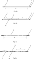
- Fig. 2a shows a cross section through the textile fabric of a single future precut area or precut position D.
- the side facing upwards in figures 2a-c and Figures 3a, 3b, 4a, and 4b is the A-side, i.e. the side of the fabric that will be visible on the final product, whereas the side facing downwards in these figures is the B-side, i.e. the side of the fabric that will not be visible on the final product.
- a local enhancement 4a,4b is added at some position of the production line 10.
- the local enhancement 4a is based on the addition of material within the precut area D, as is the case, e.g., when printing techniques are used to create the local enhancement 4a.
- a local enhancement 4b is created without material addition, but rather by removing material from the precut area D, which can be realized, e.g. by application of laser radiation, UV radiation, sandblasting, or heat radiation, or plasma treatment.
- Figures 3a and 3b show cross section of a single future precut area or precut position D as obtained after a first and a further intermediate step of a first embodiment of the invention, respectively.
- a frame made of stiffer mesh is provided around the precut area or precut position D, thus forming a stiffer mesh area 5, which leads to the configuration shown in Figure 3b after the addition of the local enhancements 4a, 4b.
- Figures 4a and 4b show cross section of a single future precut area or precut position D as obtained after a first and a further intermediate step of a second embodiment of the invention, respectively.
- FIG 4a shows that several stripes or other local geometrical shapes positioned inside the precut shape that are made of stiffer mesh and therefore define several stiffer mesh areas 5 are provided within the precut area or precut position D, leading to configuration shown in Figure 4b after the addition of the local enhancements 4a, 4b.
- some of the stripes are located in areas in which a local enhancement 4a, 4b is performed, wherein others are located in areas in which no local enhancement is performed.
Landscapes
- Engineering & Computer Science (AREA)
- Textile Engineering (AREA)
- Treatment Of Fiber Materials (AREA)
- Woven Fabrics (AREA)
Abstract
Description
- In many cases, it is desired to use textiles with local enhancements, such as printed or lighting patterns, which are to be created at distinct and well-defined positions of the fabric obtained from previous processing steps.
- However, bearing in mind that most textiles are easily deformable, interactions that are necessary to create the local enhancement can expose the fabric to stress and induce local strains which in turn lead to distortion and deformation of the fabric and thus reduce the precision of the dimensional specification of the local enhancement on the final product.
- Accordingly, the problem of the invention is to provide a method for producing a textile with local enhancement that allows for a more precise dimensional specification of the local enhancement and to provide a textile with more precisely located local enhancement.
- This problem is solved by a method for producing a textile fabric with local enhancement that allows for a more precise dimensional specification of the local enhancement with the features of
claim 1 and a textile fabric with the features ofclaim 10. The features of the dependent claims describe advantageous embodiments of the invention. - In the method for producing a textile with local enhancement according to the invention, the local enhancement is applied to the textile fabric at locations located within precut positions (i.e. predefined areas, which may also be called precut area, of the textile fabric panel or roll that is manufactured that will be used when the fabric is attached to a final product, especially during automated serial production of such products) that are spaced-apart from each other by a distance which may or may not be variable.
- According to the invention, the textile fabric is fabricated with stiffer mesh areas that are created at the border of and/or inside the precut positions. This can be done by suitable programming of the manufacturing machine which creates the fabric. In both variants, the internal stress in the area used for the final product is significantly reduced when the precut is separated (preferably by cutting) from the textile raw material (preferably a roll of textile) and the precut area has a more predictable dimensional behavior.
- If the stiffer mesh areas are created completely outside of the precut positions in accordance to a preferred embodiment of the invention, it is guaranteed that the visual impression of the precut position and especially of the local enhancement will not be influenced in a negative way and does not provide distortion. Furthermore, as the stiffer mesh might surround the precut, and as the stiffer mesh become partially a part of the precut, internal strains are frozen into the area surrounded by the stiffer mesh.
- Conversely, however, it can also be advantageous if the stiffer mesh areas are created at least partly within the precut positions, because this can lead to an even better positional control and may even be used in the design of the local enhancement.
- If at least one stiffer mesh area is created in the shape of a frame, this contributes to improved positional control in all directions.
- According to another embodiment of the method, at least part of at least one stiffer mesh area is created in an area in which local enhancement is applied. This can reduce the strain that is induced to the textile fabric during application of the local enhancement.
- The local enhancement can be created by addition of material, like printed inks, local coating of plastics or rubbers or welding of pattern pieces.
- Alternatively or additionally, in other embodiments the local enhancement may also be created by surface modification, e.g. brought about by cutting or etching with a laser or UV radiation, sandblasting, application of chemical agents or mechanically using blades and/or tools.
- Preferably, the position of the precut position is monitored with physical indexation, a camera monitoring system and/or a laser monitoring system.
- The positioning control can be increased even further if prior to the application of the local enhancement, a protective stabilizing film is applied to the textile fabric at least in parts of the regions of the textile fabric that are located between two subsequent precut positions.
- The textile fabric according to the invention has local enhancements applied to the textile fabric at locations located within precut positions that are spaced-apart from each other by a distance d which may or may not be variable. An essential feature of the invention is that the fabric comprises stiffer mesh areas that are located at the border of and/or inside the precut positions. In this way, positional stability is increased due to the reduction or freeze of internal strains.
- According to one preferred embodiment, the stiffer mesh areas are located completely outside of the precut positions, so that it will be guaranteed that there will be no adverse effect on the visual effect obtained by the local enhancement.
- If, however, the stiffer mesh areas are located at least partly within the pre-cut positions, positional control may be improved; in addition in this way another way of creating visual effects becomes available.
- If at least one stiffer mesh area is arranged in the shape of a frame, positional decoupling is achieved in all directions.
- It can also be advantageous if at least part of at least one stiffer mesh area is located in an area in which local enhancement is applied. This can lead to a notable reduction of the strain that is applied to the fabric during the local enhancement process.
- The local enhancement may be formed by addition of material and/or by surface modification.
- Next, the invention is explained using figures that illustrate specific embodiments of the invention. The figures show:
- Fig. 1
- A schematic overview over a production line for producing a fabric with local enhancement,
- Fig. 2a
- a cross section of a single future precut area,
- Fig. 2b
- an example for a local enhancement based on the addition of material within the precut area,
- Fig. 2c
- an example for a local enhancement based on a surface treatment,
- Fig. 3a
- a cross section of a single future precut area as obtained after a first intermediate step of a first embodiment of the invention,
- Fig. 3b
- the cross section of
fig. 3a after a further intermediate step of the first embodiment of the invention, - Fig. 4a
- a cross section of a single future precut area as obtained after a first intermediate step of a second embodiment of the invention, and
- Fig. 4b
- the cross section of
fig. 4a after a further intermediate step of the second embodiment of the invention. -
Figure 1 shows a schematic overview over aproduction line 10 for producing atextile fabric 1 with local enhancement. Atextile manufacturing machine 2 provides the fabric, typically from yarns which have been created from fibers as an output. This textile fabric is moved in the warp direction indicated by the double arrow, e.g. pulled by a motorized axis which winds the final product to atextile roll 3, thus inducing a well-defined strain on the fabric. - Especially if the
textile roll 3 is to be processed automatically, future precut areas or precut positions D1, D2 comprising the local enhancement that are separated by a separation distance d1, d2 are prepared at defined positions of the length of the fabric that forms thetextile roll 3. The thus defined positional information allows a further machine (not shown) which processes thetextile roll 3 and applies the precut areas D1, D2 including the local enhancement in a reproducible way to the product for which the fabric with the local enhancement is used. More specifically, in this way it can be achieved that the local enhancement is oriented in an identical way for each product produced by this further machine. -
Fig. 2a shows a cross section through the textile fabric of a single future precut area or precut position D. The side facing upwards infigures 2a-c andFigures 3a, 3b, 4a, and 4b is the A-side, i.e. the side of the fabric that will be visible on the final product, whereas the side facing downwards in these figures is the B-side, i.e. the side of the fabric that will not be visible on the final product. - As shown in
Figure 2b and 2c , in a defined area A, which is located within the future precut area or precut position D, more precisely beginning at a distance x from its left boundary and ending at a distance y from its right boundary, alocal enhancement production line 10. Infigure 2b , thelocal enhancement 4a is based on the addition of material within the precut area D, as is the case, e.g., when printing techniques are used to create thelocal enhancement 4a. Infigure 2c , alocal enhancement 4b is created without material addition, but rather by removing material from the precut area D, which can be realized, e.g. by application of laser radiation, UV radiation, sandblasting, or heat radiation, or plasma treatment. Of course, it is also possible to create a local enhancement using a mixture of techniques based on addition and removal of material, respectively. -
Figures 3a and 3b show cross section of a single future precut area or precut position D as obtained after a first and a further intermediate step of a first embodiment of the invention, respectively. As recognized infigure 3a , a frame made of stiffer mesh is provided around the precut area or precut position D, thus forming astiffer mesh area 5, which leads to the configuration shown inFigure 3b after the addition of thelocal enhancements -
Figures 4a and 4b show cross section of a single future precut area or precut position D as obtained after a first and a further intermediate step of a second embodiment of the invention, respectively. As recognized infigure 4a , several stripes or other local geometrical shapes positioned inside the precut shape that are made of stiffer mesh and therefore define severalstiffer mesh areas 5 are provided within the precut area or precut position D, leading to configuration shown inFigure 4b after the addition of thelocal enhancements local enhancement -
- 1
- textile fabric
- 2
- manufacturing machine
- 3
- roll
- 4a, 4b
- local enhancement
- 5
- stiffer mesh area
- 10
- production line
- A
- area
- D, D1, D2
- precut positon
- d1, d2, x, y
- distance
Claims (16)
- A method for producing a textile fabric (1) with local enhancement (4a, 4b, wherein the local enhancement (4a, 4b) is applied to the textile fabric (1) at locations located within precut positions (D, D1, D2) that are spaced-apart from each other by a distance (d1, d2) which may or may not be variable,
characterized in that the textile fabric (1) is fabricated with stiffer mesh areas (5) that are created at the border of and/or inside the precut positions (D, D1, D2). - The method according to claim 1, wherein the stiffer mesh areas (5) are created completely outside of the precut positions (D, D1, D2).
- The method according to claim 1, wherein the stiffer mesh areas (5) are created at least partly within the precut positions (D, D1, D2).
- The method according to one of claims 1 to 3, wherein at least one stiffer mesh area (5) is created in the shape of a frame.
- The method according to one of claims 1 to 4, wherein at least part of at least one stiffer mesh area (5) is created in an area in which local enhancement (4a, 4b) is applied.
- The method according to one of claims 1 to 5, wherein the local enhancement (4a, 4b) is created by addition of material.
- The method according to one of claims 1 to 5, wherein the local enhancement (4a, 4b) is created by surface modification.
- The method according to one of claims 1 to 7, wherein the position of the precut position (D, D1, D2) is monitored with physical indexation, a camera monitoring system and/or a laser monitoring system.
- The method according to one of claims 1 to 8, wherein prior to the application of the local enhancement (4a, 4b), a protective stabilizing film is applied to the textile fabric (1) at least in parts of the regions of the textile fabric (1) that are located between two subsequent precut positions (D, D1, D2).
- A textile fabric (1) with local enhancements (4a, 4b) applied to the textile fabric (1) at locations located within precut positions (D, D1, D2) that are spaced-apart from each other by a distance (d1, d2) which may or may not be variable, characterized in that the textile fabric (1) comprises stiffer mesh areas (5) that are located at the border of and/or inside the precut positions (D, D1, D2).
- The textile fabric (1) according to claim 10, wherein the stiffer mesh areas (5) are located completely outside of the precut positions (D, D1, D2).
- The textile fabric (1) according to claim 10, wherein the stiffer mesh areas (5) are located at least partly within the precut positions (D, D1, D2).
- The textile fabric (1) according to one of claims 10 to 12, wherein at least one stiffer mesh area (6) is arranged in the shape of a frame.
- The textile fabric (1) according to one of claims 10 to 13, wherein at least part of at least one stiffer mesh area (5) is located in an area in which local enhancement (4a, 4b) is applied.
- The textile fabric (1) according to one of claims 10 to 14, wherein the local enhancement (4a, 4b) comprises added material.
- The textile fabric (1) according to one of claims 10 to 14, wherein the local enhancement (4a, 4b) comprises a surface modification.
Applications Claiming Priority (1)
| Application Number | Priority Date | Filing Date | Title |
|---|---|---|---|
| US202263408632P | 2022-09-21 | 2022-09-21 |
Publications (2)
| Publication Number | Publication Date |
|---|---|
| EP4343053A2 true EP4343053A2 (en) | 2024-03-27 |
| EP4343053A3 EP4343053A3 (en) | 2024-04-17 |
Family
ID=88021126
Family Applications (2)
| Application Number | Title | Priority Date | Filing Date |
|---|---|---|---|
| EP23197240.7A Pending EP4343052A3 (en) | 2022-09-21 | 2023-09-13 | Method for producing a textile with local enhancement and textile with local enhancement |
| EP23197241.5A Pending EP4343053A3 (en) | 2022-09-21 | 2023-09-13 | Method for producing a textile with local enhancement and textile with local enhancement |
Family Applications Before (1)
| Application Number | Title | Priority Date | Filing Date |
|---|---|---|---|
| EP23197240.7A Pending EP4343052A3 (en) | 2022-09-21 | 2023-09-13 | Method for producing a textile with local enhancement and textile with local enhancement |
Country Status (2)
| Country | Link |
|---|---|
| EP (2) | EP4343052A3 (en) |
| CN (2) | CN117738010A (en) |
Family Cites Families (9)
| Publication number | Priority date | Publication date | Assignee | Title |
|---|---|---|---|---|
| US5878645A (en) * | 1997-09-12 | 1999-03-09 | Streit; Carl | Accordion fold curtains and method of manufacture |
| US20040050506A1 (en) * | 2002-07-31 | 2004-03-18 | Gerd Haiber | Decorative hanging fabric panels with integrated stiffend areas |
| US7100941B2 (en) * | 2003-02-24 | 2006-09-05 | Collins & Aikman | Pre-weakening of fabric covered airbag doors |
| EP2239139B1 (en) * | 2009-04-10 | 2013-03-20 | Procraft Development B.V. | Composite stencils and methods of making composite stencils |
| JP6134222B2 (en) * | 2013-07-26 | 2017-05-24 | 日本ダム株式会社 | Manufacturing method of cloth emblem base material |
| GB2539508A (en) * | 2015-06-19 | 2016-12-21 | Dst Innovations Ltd | A method for making patterned conductive textiles |
| CN110582409A (en) * | 2017-01-17 | 2019-12-17 | 塞奇机动车内饰股份有限公司 | Rotary Screen Pattern Printing of Polyurethane Resin on Textiles |
| EP3354453B1 (en) * | 2017-01-26 | 2020-09-23 | Autoneum Management AG | Acoustic carpet for vehicles |
| CN209135547U (en) * | 2018-11-22 | 2019-07-23 | 深圳市娜尔思时装有限公司 | A kind of crimped stamp moulding clothes |
-
2023
- 2023-09-13 EP EP23197240.7A patent/EP4343052A3/en active Pending
- 2023-09-13 EP EP23197241.5A patent/EP4343053A3/en active Pending
- 2023-09-21 CN CN202311219578.1A patent/CN117738010A/en active Pending
- 2023-09-21 CN CN202311227375.7A patent/CN117738011A/en active Pending
Also Published As
| Publication number | Publication date |
|---|---|
| EP4343052A2 (en) | 2024-03-27 |
| CN117738010A (en) | 2024-03-22 |
| EP4343053A3 (en) | 2024-04-17 |
| EP4343052A3 (en) | 2024-04-17 |
| CN117738011A (en) | 2024-03-22 |
Similar Documents
| Publication | Publication Date | Title |
|---|---|---|
| JP5352445B2 (en) | Manufacturing method of laminated iron core | |
| JP2010265574A (en) | Method for producing air-bag | |
| JP6650646B2 (en) | NC control program, NC control device, NC processing system, NC control method, and two-dimensional code manufacturing method | |
| DE102012224359B4 (en) | Process for producing stamps for devices for plasmonic nanolithography | |
| EP4343052A2 (en) | Method for producing a textile with local enhancement and textile with local enhancement | |
| CN111188008B (en) | Metal mask strip, metal mask plate and manufacturing method thereof, and glass photomask | |
| KR101200381B1 (en) | Progressive designed allow processing of LCD monitor Backplate, and the manufacturing method and manufacturing molds | |
| JP3819131B2 (en) | Piston ring manufacturing method | |
| JPH0648344B2 (en) | Method for manufacturing master for forming projection screen and chisel used therefor | |
| US5233754A (en) | Method for forming perforations on a printed circuit board | |
| KR102067706B1 (en) | Method for manufacturing bearing shield for motors | |
| KR100787513B1 (en) | Shadow mask and plate member therefor | |
| CN1023851C (en) | Manufacturing method for electrode of electron gun of cathode ray tube | |
| JPH05220753A (en) | Method for manufacturing mold for tire vulcanization molding | |
| TWI849866B (en) | Method for manufacturing screen printing plate component | |
| KR102067700B1 (en) | Apparatus for manufacturing bearing shield for motors | |
| KR20210056151A (en) | Lens Spacer And Lens Module Comprising The Same | |
| JP3085473U (en) | Metal washer | |
| DE102024201114A1 (en) | Method for producing a vehicle tire | |
| KR100522534B1 (en) | apparatus and method for manufacturing core lamination | |
| EP4078667B1 (en) | Detachment device and method for detaching a semiconductor layer from a substrate | |
| JPH04280661A (en) | Manufacture of semiconductor device lead frame | |
| KR200175590Y1 (en) | Machining punches for electron gun parts | |
| KR920007387B1 (en) | The making method for support spring | |
| JP2606977B2 (en) | Method for manufacturing lead frame for semiconductor device |
Legal Events
| Date | Code | Title | Description |
|---|---|---|---|
| PUAI | Public reference made under article 153(3) epc to a published international application that has entered the european phase |
Free format text: ORIGINAL CODE: 0009012 |
|
| STAA | Information on the status of an ep patent application or granted ep patent |
Free format text: STATUS: THE APPLICATION HAS BEEN PUBLISHED |
|
| PUAL | Search report despatched |
Free format text: ORIGINAL CODE: 0009013 |
|
| AK | Designated contracting states |
Kind code of ref document: A2 Designated state(s): AL AT BE BG CH CY CZ DE DK EE ES FI FR GB GR HR HU IE IS IT LI LT LU LV MC ME MK MT NL NO PL PT RO RS SE SI SK SM TR |
|
| AK | Designated contracting states |
Kind code of ref document: A3 Designated state(s): AL AT BE BG CH CY CZ DE DK EE ES FI FR GB GR HR HU IE IS IT LI LT LU LV MC ME MK MT NL NO PL PT RO RS SE SI SK SM TR |
|
| RIC1 | Information provided on ipc code assigned before grant |
Ipc: A41D 27/00 20060101ALI20240313BHEP Ipc: D06M 23/16 20060101AFI20240313BHEP |
|
| STAA | Information on the status of an ep patent application or granted ep patent |
Free format text: STATUS: REQUEST FOR EXAMINATION WAS MADE |
|
| 17P | Request for examination filed |
Effective date: 20241007 |
|
| RBV | Designated contracting states (corrected) |
Designated state(s): AL AT BE BG CH CY CZ DE DK EE ES FI FR GB GR HR HU IE IS IT LI LT LU LV MC ME MK MT NL NO PL PT RO RS SE SI SK SM TR |
|
| P01 | Opt-out of the competence of the unified patent court (upc) registered |
Free format text: CASE NUMBER: UPC_APP_0003360_4343053/2026 Effective date: 20260130 |
|
| RAP3 | Party data changed (applicant data changed or rights of an application transferred) |
Owner name: MOTHERSON INNOVATIONS COMPANY LIMITED |