EP4343042A1 - Fiber waste collection device - Google Patents
Fiber waste collection device Download PDFInfo
- Publication number
- EP4343042A1 EP4343042A1 EP23196196.2A EP23196196A EP4343042A1 EP 4343042 A1 EP4343042 A1 EP 4343042A1 EP 23196196 A EP23196196 A EP 23196196A EP 4343042 A1 EP4343042 A1 EP 4343042A1
- Authority
- EP
- European Patent Office
- Prior art keywords
- fiber waste
- suction
- opening
- compressed air
- transfer pipe
- Prior art date
- Legal status (The legal status is an assumption and is not a legal conclusion. Google has not performed a legal analysis and makes no representation as to the accuracy of the status listed.)
- Granted
Links
Images




Classifications
-
- D—TEXTILES; PAPER
- D01—NATURAL OR MAN-MADE THREADS OR FIBRES; SPINNING
- D01H—SPINNING OR TWISTING
- D01H11/00—Arrangements for confining or removing dust, fly or the like
- D01H11/005—Arrangements for confining or removing dust, fly or the like with blowing and/or suction devices
-
- B—PERFORMING OPERATIONS; TRANSPORTING
- B65—CONVEYING; PACKING; STORING; HANDLING THIN OR FILAMENTARY MATERIAL
- B65H—HANDLING THIN OR FILAMENTARY MATERIAL, e.g. SHEETS, WEBS, CABLES
- B65H54/00—Winding, coiling, or depositing filamentary material
- B65H54/70—Other constructional features of yarn-winding machines
- B65H54/702—Arrangements for confining or removing dust
-
- B—PERFORMING OPERATIONS; TRANSPORTING
- B65—CONVEYING; PACKING; STORING; HANDLING THIN OR FILAMENTARY MATERIAL
- B65H—HANDLING THIN OR FILAMENTARY MATERIAL, e.g. SHEETS, WEBS, CABLES
- B65H54/00—Winding, coiling, or depositing filamentary material
- B65H54/70—Other constructional features of yarn-winding machines
- B65H54/707—Suction generating system
-
- B—PERFORMING OPERATIONS; TRANSPORTING
- B65—CONVEYING; PACKING; STORING; HANDLING THIN OR FILAMENTARY MATERIAL
- B65H—HANDLING THIN OR FILAMENTARY MATERIAL, e.g. SHEETS, WEBS, CABLES
- B65H2701/00—Handled material; Storage means
- B65H2701/30—Handled filamentary material
- B65H2701/31—Textiles threads or artificial strands of filaments
Definitions
- the present invention relates to a fiber waste collection device arranged for a textile machine so as to collect fiber waste generated in the textile machine.
- Patent Document 1 discloses a suction device for continuously running multi-threads including a suctioning pipe arranged with a plurality of suctioning ports, a lint collection container connected to an end of the suctioning pipe, and a negative pressure pump or suction blower connected to the lint collection container.
- the pressure within the suctioning pipe becomes negative due to the operation of the negative pressure pump or suction blower, and the fiber waste as lint suctioned into the suctioning pipe from the plurality of suctioning ports is suctioned through the suctioning pipe to be collected in the lint collection container.
- Patent Document 1 Japanese Patent Application Publication No. H06-40661
- the fiber waste is suctioned through the suctioning pipe to be collected as a result of causing the negative pressure pump or suction blower to operate, where the pump or blower is connected via the lint collection container to a downstream end side in a suction direction of the suctioning pipe having a function of transferring therethrough the fiber waste.
- the sound generated upon operation of such a negative pressure pump or suction blower is loud, at a level of noise, which results in deterioration of the working environment.
- the present invention has been made in view of the above-described technical problems, and an objective thereof is to provide a fiber waste collection device capable of reducing the sound generated during the collection of fiber waste so as to suppress the generation of noise while improve the working environment.
- a first aspect of the present invention is a fiber waste collection device arranged for a textile machine so as to collect fiber waste generated in the textile machine, the fiber waste collection device comprising:
- compressed air injected into the suction pipe from the compressed air injection nozzle hole of each of the plurality of suction units generates air flow capable of carrying the fiber waste toward a side of the fiber waste transfer pipe within the suction pipe, and thereby, the fiber waste is suctioned from the suction port of the suction pipe.
- the fiber waste suctioned from the suction port flows into the fiber waste transfer pipe.
- the fiber waste having flown into the fiber waste transfer pipe from the suction port is transferred through the fiber waste transfer pipe with the aid of compressed air having flown from the connection unit at one end side of the fiber waste transfer pipe so as to be collected in the fiber waste collection unit.
- any negative pressure pump or suction blower to suction an interior of the fiber waste transfer pipe at a downstream end side thereof.
- such a negative pressure pump or suction blower as a noise source can be eliminated, thereby capable of reducing the sound generated during the collection of fiber waste so as to suppress the generation of noise while improve the working environment.
- the suction port can be opened and closed by means of the opening/closing member in a state where the suction port of each of the plurality of suction units is closed by means of the opening/closing member. It is possible, therefore, to prevent fibers other than the fiber waste from being erroneously suctioned from the suction port.
- the opening/closing control valve of the connection unit when the suction port of each of the plurality of suction units is opened, the opening/closing control valve of the connection unit is opened to supply compressed air toward the fiber waste transfer pipe, and thereby, the suctioned fiber waste is transferred through the fiber waste transfer pipe so as to be collected in the fiber waste collection unit.
- Compressed air can, therefore, be supplied to the fiber waste transfer pipe only when the suction port is opened so that a suction operation is performed.
- compressed air can be supplied efficiently while suppressing a wasteful supply thereby capable of improving the energy efficiency.
- a power consumption is significantly different depending upon an opening/closing state of an opening at an end side of the suctioning pipe and an opening/closing state of a suctioning port.
- a power consumption is the minimum when both the end side of the suctioning pipe and the suctioning port are opened, while a power consumption increases significantly when either the end side of the suctioning pipe or the suctioning port is closed, and a power consumption increases further significantly when both the end side of the suctioning pipe and the suctioning port are closed.
- the controller performs an opening control of the opening/closing control valve of the connection unit when causing the opening/closing member to perform an opening operation of the suction port
- the controller includes both of: a case where the controller performs control such that an opening operation of the opening/closing member is performed concurrently with opening of the opening/closing control valve; and a case where the controller performs control such that an opening operation of the opening/closing member is performed before or after opening of the opening/closing control valve.
- a second aspect of the present invention is the fiber waste collection device in the above-described first aspect, wherein
- the opening/closing control valve of the connection unit corresponding to the fiber waste transfer pipe arranged with such a certain set of plurality of suction units each having the opened suction port is opened, and thereby, compressed air is supplied to such a fiber waste transfer pipe.
- compressed air can be supplied to only a fiber waste transfer pipe corresponding to the certain set of plurality of suction units required to suction the fiber waste, and thereby, the suctioned fiber waste can be collected.
- a third aspect of the present invention is the fiber waste collection device in the above-described first or second aspect, wherein the suction pipe is smaller in diameter than a fiber waste transfer pipe.
- a diameter of the suction pipe is smaller than that of the fiber waste transfer pipe, and it is possible, therefore, to efficiently suppress the backflow of air flow capable of carrying the fiber waste toward the fiber waste transfer pipe within the suction pipe, and thereby, the fiber waste can be efficiently suctioned from the suction port of the suction pipe.
- a fourth aspect of the present invention is the fiber waste collection device in any one of the above-described first to third aspects, wherein
- compressed air for transferring the fiber waste flowing into the fiber waste collection container is discharged to an exterior from the opening of the fiber waste collection container while the fiber waste being efficiently collected in the fiber waste collection container. Since the opening of the fiber waste collection container is opened at least either upwardly or laterally, a large opening can be formed at an upper surface or side surface of the fiber waste collection container. Compressed air having flown from the fiber waste transfer pipe can, therefore, be efficiently discharged to an exterior of the fiber waste collection container, and thereby, the collection efficiency of the fiber waste can be enhanced.
- a fifth aspect of the present invention is the fiber waste collection device in any one of the above-described first to fifth aspects, wherein a flow rate of compressed air flowing from the connection unit and flowing through a fiber waste transfer pipe is set to be 1000 m/min or higher.
- the fiber waste transfer pipe it is possible to prevent the fiber waste transfer pipe from being clogged with the fiber waste transferred, with the aid of compressed air having a flow rate as high as 1000 m/min, through the fiber waste transfer pipe. Further, after having conducted verification as a function of various flow rates of compressed air flowing in the fiber waste transfer pipe, the inventor has found that there is an increasing probability that clogging of the fiber waste transfer pipe with the fiber waste occurs when a flow rate of compressed air is lower than 1000 m/min. On the other hand, the inventor has found that clogging of the fiber waste transfer pipe with the fiber waste can be prevented when a flow rate of compressed air is 1000 m/min or higher.
- the fiber waste collection device does not necessarily include all of the above-described first to fifth aspects.
- the invention of the fiber waste collection device in the above-described first aspect e.g., does not need to encompass all of the above-described second to fifth aspects.
- the fiber waste collection device according to the present invention may be obtained by arbitrarily combining the above-described first aspect and any of the above-described second to fifth aspects to such an extent that consistency can be achieved.
- the present invention it is possible to provide a fiber waste collection device capable of reducing the sound generated during the collection of fiber waste so as to suppress the generation of noise while improve the working environment.
- the present invention can be widely applied to various uses as a fiber waste collection device to be arranged in a textile machine such as a false-twisting machine so as to collect fiber waste generated in the textile machine.
- FIG. 1 is a schematic view showing a false-twisting machine 101 as a textile machine to be arranged with a fiber waste collection device 1.
- FIG. 2 is a schematic view showing an example of fiber waste collection device 1 according to an embodiment of the present invention along with a compressed air supply source 100.
- a fiber waste collection device 1 is arranged in a textile machine such as a false-twisting machine 101 or spinning machine.
- the false-twisting machine 101 will be described as an example of textile machine arranged with the fiber waste collection device 1.
- the false-twisting machine 101 arranged with the fiber waste collection device 1 will be described, and subsequently, the fiber waste collection device 1 according to an embodiment of the present invention will be described.
- an up-and-down direction, a forward-and-backward direction, and a left-and-right direction in the false-twisting machine 101 are defined as shown in FIG. 1 .
- the false-twisting machine 101 is configured, as a textile machine, to false-twist thermoplastic synthetic fibers such as polyester and polyamide so as to impart crimps to the false-twisted fibers, thereby producing highly stretchable textured yarns.
- a main machine base 102 is arranged so as to extend in an up-and-down direction.
- the false-twisting machine 101 includes: a yarn feeding creel 104 arranged so as to face the main machine base 102 across a work space 103 and holding a plurality of yarn feeding packages 105; a false-twisting device 106 arranged above the main machine base 102 so as to false-twist a fiber Y as a yarn supplied from the yarn feeding creel 104; a winder 107 arranged on the main machine base 102 so as to wind the false-twisted fiber Y obtained in the false-twisting device 106; and the like.
- the winders 107 are arranged in four stages along an up-and-down direction.
- a plurality of winders 107 are arranged side by side along a forward-and-backward direction in each of the first to fourth stages. It is to be noted that a forward-and-backward direction in which the plurality of winders 107 are arranged in each of the four stages arranged in an up-and-down direction is a direction along a horizontal direction as well as a direction perpendicular to a direction (left-and-right direction) in which the yarn feeding creel 104 and the main machine base 102 are arranged.
- a first feeding roller 108, a shifter guide 109, a first heating device 110, and a cooling device 111 are arranged in this order from an upstream side in a yarn traveling direction on a yarn path from the yarn feeding creel 104 to the false-twisting device 106.
- a second feeding roller 112, an interlace nozzle 113, a second heating device 114, a third feeding roller 115, and an oiling roller 116 are arranged in this order from an upstream side in a yarn traveling direction on a yarn path from the false-twisting device 106 to the winder 107.
- the first feeding roller 108 is arranged above the work space 103.
- the first heating device 110 is arranged above the work space 103 and further above the first feeding roller 108.
- the cooling device 111 is arranged closer to the main machine base 102 than to the first heating device 110 above the work space 103.
- the first heating device 110 and the cooling device 111 are arranged above the work space 103 so as to extend obliquely upward while being separated from the main machine base 102.
- the shifter guide 109 is arranged between the first feeding roller 108 and the first heating device 110 in an up-and-down direction, and is used to pass a fiber Y through the first heating device 110 and the cooling device 111 when threading a yarn on the false twisting machine 101.
- the second feeding roller 112 is arranged above the main machine base 102.
- the interlace nozzle 113 is arranged above the main machine base 102 and below the second feeding roller 112.
- the second heating device 114 is arranged on the main machine base 102 and is arranged on a back side of the winder 107 when viewed from the work space 103 so as to extend in an up-and-down direction from the first stage to the fourth stage of the four-stages of winders 107.
- the devices are laid out in such a manner, and a yarn path from the yarn feeding creel 104 to the winder 107 is formed so as to surround the work space 103.
- a fiber Y as a yarn supplied from the yarn feeding creel 104 is carried through the above-described devices and wound on the winder 107 to form a package 117.
- the first to third feeding rollers (108, 112, 115) are rollers for feeding a fiber Y from an upstream side to a downstream side in a yarn traveling direction.
- Each yarn feed velocity is set such that the yarn feed velocity of the second feeding roller 112 is faster than that of the first feeding roller 108.
- the fibers Y are, therefore, drawn between the first feeding roller 108 and the second feeding roller 112.
- each yarn feeding velocity is set such that the yarn feeding velocity of the third feeding roller 115 is slower than that of the second feeding roller 112.
- the fiber Y is, therefore, loosened between the second feeding roller 112 and the third feeding roller 115.
- the fibers Y drawn between the first feeding roller 108 and the second feeding roller 112 are twisted by the false-twisting device 106 that is, e.g., a friction disk-type twister so as to be carried.
- the twist formed by the false-twisting device 106 propagates to the first feeding roller 108, and the fibers Y drawn to be twisted are heated by the first heating device 110 and thereafter cooled by the cooling device 111, and thereby, the twist is fixed.
- the twisted and heat-set fibers Y are untwisted before reaching the second feeding roller 112.
- the fibers Y drawn and false-twisted in such a manner are appropriately entangled in the interlace nozzle 113 so as have bundling properties, and thereafter, are subjected to relaxation heat treatment in the second heating device 114 and wound on a paper tube by the winder 107 via the oiling roller 116 so as to form the package 117.
- the fiber Y supplied to the winder 107 is cut.
- the fully-wound package 117 is removed from the winder 107.
- the package 117 wound fully and removed from the winder 107 is caused to move along a rail 118 and is once stocked on the rail 118.
- the fiber waste collection device 1 of an embodiment according to the present invention is arranged in the false-twisting machine 101 as the textile machine described above, and is used to collect fiber waste generated in the false-twisting machine 101.
- the fiber waste collection device 1 is used to collect fiber waste generated as fibers Y, e.g., when the package 117 is replaced.
- fiber waste generated as the fiber Y continuing to be supplied to a region near the winder 107 is collected by the fiber waste collection device 1. Then, when a new paper tube is attached to the winder 107 and the operation of winding the fiber on the paper tube is resumed, the collection of fiber waste of the fibers Y by the fiber waste collection device 1 is stopped. It is to be noted that fiber waste of the fibers Y includes not only the fiber waste in a state of yarn but also the fiber waste in a state of yarn-like cotton.
- the fiber waste collection device 1 of an embodiment according to the present invention will be described below.
- FIG. 3 is a schematic view showing a fiber waste collection device 1 according to an embodiment of the present invention.
- the fiber waste collection device 1 mainly includes, e.g., a plurality of fiber waste transfer pipes 11, a plurality of connection units 12 arranged corresponding to the plurality of fiber waste transfer pipes 11, respectively, a fiber waste collection unit 13, and a controller 14 (see FIG. 6 that will be described later).
- the fiber waste collection device 1 is arranged in the false-twisting machine 101 described above.
- the plurality of fiber waste transfer pipes 11 of the fiber waste collection device 1 are arranged corresponding to their respective stages of the winders 107 arranged vertically in four stages in the false-twisting machine 101.
- the fiber waste collection device 1 of an embodiment according to the present invention is, therefore, arranged with, e.g., four fiber waste transfer pipes 11.
- the fiber waste transfer pipes 11 arranged correspondingly to their respective stages of the winders 107 arranged vertically in four stages are arranged so as to extend along a forward-and-backward direction. In each stage of winders 107 from the first stage to the fourth stage, winders 107 are arranged side by side in a forward-and-backward direction.
- the fiber waste transfer pipes 11 are also arranged to extend along a forward-and-backward direction in which the winders 107 are arranged side by side. Each of the fiber waste transfer pipes 11 suctions and transfers fiber waste generated as fibers Y from a region near each of the winders 107 arranged side by side in a backward-and-forward direction at each stage of the winders 107 arranged vertically in four stages. Each of the four fiber waste transfer pipes 11 is connected to the fiber waste collection unit 13. Fiber waste of the fibers Y transferred through each fiber waste transfer pipe 11 is carried to the fiber waste collection unit 13 so as to be collected in the fiber waste collection unit 13.
- the fiber waste collection device 1 is used to collect fiber waste generated as fibers Y continuously supplied to a region near the winder 107 from the yarn feeding creel 104 via the devices (110, 111, 106, 114) when the fiber Y is threaded on the false-twisting machine 101 or when the package 117 formed on the winder 107 of the false-twisting machine 101 is replaced. Structural details of the fiber waste collection device 1 will be described below.
- the fiber waste transfer pipe 11 is arranged with a plurality of suction units 15 for suctioning fiber waste generated as fibers Y, and is configured as a pipe through which the fiber waste suctioned from the plurality of suction units 15 is transferred.
- the suction unit 15 for suctioning fiber waste of the fibers Y will be described later.
- the fiber waste transfer pipe 11 is arranged, e.g., in a shape of a hollow circular pipe.
- a plurality of fiber waste transfer pipes 11 are arranged, and in an embodiment according to the present invention, four fiber waste transfer pipes 11 are arranged correspondingly to the winders 107 arranged vertically in four stages in the false-twisting machine 101.
- a first fiber waste transfer pipe 11a corresponding to a winder 107 on a first stage at a bottom, a second fiber waste transfer pipe 11b corresponding to a winder 107 on a second stage from the bottom, a third fiber waste transfer pipe 11c corresponding to a winder 107 on a third stage from the bottom, and a fourth fiber waste transfer pipe 11d corresponding to a winder 107 on a fourth stage on a top are arranged.
- the fiber waste transfer pipes 11 are arranged in the false-twisting machine 101 having a longitudinal direction extending over a forward-and-backward direction. Further, each of the first to fourth fiber waste transfer pipes (11a to 11d) is arranged so as to extend in a forward-and-backward direction in a position corresponding to each stage of the winders 107 from the first stage to the fourth stage.
- Each of the fiber waste transfer pipes 11 is arranged with a connection unit 12, which will be described later, on one end side in a longitudinal direction extending over a forward-and-backward direction.
- Each of the fiber waste transfer pipes 11 is connected to a fiber waste collection unit 13 to be described later on the other end side in a longitudinal direction.
- Each of the plurality of fiber waste transfer pipes 11 (11a to 11d) is, therefore, arranged with the connection unit 12 and connected to the fiber waste collection unit 13.
- the fiber waste transfer pipe 11 is configured, as a pipe, such that compressed air is supplied from one end side thereof arranged with the connection unit 12, and the supplied compressed air is allowed to flow toward the other end side thereof connected to the fiber waste collection unit 13.
- a set of plurality of suction units 15 is arranged, as a mechanism to suction fiber waste generated as fibers Y, in each fiber waste transfer pipe 11, and a plurality of sets of the plurality of suction units 15 are arranged in the plurality of fiber waste transfer pipes 11, respectively.
- a plurality of suction units 15 are arranged side by side along a longitudinal direction of each fiber waste transfer pipe 11.
- the plurality of suction units 15 are arranged at positions of each fiber waste transfer pipe 11 corresponding to winders 107, respectively. More specifically, a plurality of winders 107 are arranged in a forward-and-backward direction at each of four stages arranged vertically in the false-twisting machine 101.
- a first suction unit 15a is arranged in the first fiber waste transfer pipe 11a
- a second suction unit 15b is arranged in the second fiber waste transfer pipe 11b
- a third suction unit 15c is arranged in the third fiber waste transfer pipe 11c
- a fourth suction unit 15d is arranged in the fourth fiber waste transfer pipe 11d. That is, a plurality of first suction units 15a as the above-described "plurality of suction units 15" are arranged side by side in the first fiber waste transfer pipe 11a.
- a plurality of second suction units 15b as the above-described "plurality of suction units 15" are arranged side by side in the second fiber waste transfer pipe 11b.
- a plurality of third suction units 15c as the above-described "plurality of suction units 15" are arranged side by side in the third fiber waste transfer pipe 11c.
- a plurality of fourth suction units 15d as the above-described "plurality of suction units 15" are arranged side by side in the fourth fiber waste transfer pipe 11d.
- FIG. 4 is a cross-sectional view of a suction unit 15 arranged on a fiber waste transfer pipe 11.
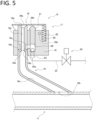
- FIG. 5 is a cross-sectional view of the suction unit 15 in a state where a suction port 16a to be described later is closed by means of an opening/closing member 19 to be described later.
- a plurality of sets of suction units 15 arranged in the first to fourth fiber waste transfer pipes (11a to 11d) are all configured in the same manner. That is, the first to fourth suction units (15a to 15d) arranged in the first to fourth fiber waste transfer pipes (11a to 11d), respectively, are all configured in the same manner.
- each suction unit 15 includes a suction pipe 16 and an opening/closing mechanism 17.
- each suction pipe 16 is a tubular member for suctioning fiber waste generated as fibers Y having a smaller diameter than that of the fiber waste transfer pipe 11, and is bent halfway to be extended.
- One end side of the suction pipe 16 communicates with the fiber waste transfer pipe 11, and the other end side of the suction pipe 16 is arranged with a suction port 16a for suctioning fiber waste of the fibers Y.
- the suction port 16a of the suction pipe 16 is opened toward an exterior.
- the suction port 16a of the suction pipe 16 is arranged in a region near the winder 107.
- the one end side of the suction pipe 16 is connected to the fiber waste transfer pipe 11 via an outlet opening 16b.
- the suction pipe 16 communicates with an interior of the fiber waste transfer pipe 11 at the outlet opening 16b.
- a suction flow path 16c extending from the suction port 16a to the outlet opening 16b is formed within an interior of the suction pipe 16. Fiber waste of the fibers Y suctioned from the suction port 16a is caused to move through the suction flow path 16c and flows into the fiber waste transfer pipe 11 from the outlet opening 16b.
- each suction pipe 16 is connected obliquely to the fiber waste transfer pipe 11.
- the suction pipe 16 is connected to the fiber waste transfer pipe 11 at an acute angle with respect to a direction from an upstream side to a downstream side of compressed air flowing through the fiber waste transfer pipe 11. That is, the suction pipe 16 is connected to the fiber waste transfer pipe 11 at an angle as an acute angle formed with respect to a direction from one end side arranged with the connection unit 12 to the other end side connected to the fiber waste collection unit 13.
- each suction pipe 16 is arranged with a compressed air injection nozzle hole 16d and a guide path 16e.
- the compressed air injection nozzle hole 16d is a hole for injecting compressed air into the suction pipe 16 between one end side arranged with each outlet opening 16b and the other end side arranged with each suction port 16a.
- the compressed air injection nozzle hole 16d is formed so as to inject compressed air toward one end side as the outlet opening 16b side within the suction pipe 16.
- two compressed air injection nozzle holes 16d are formed.
- Each of the two compressed air injection nozzle holes 16d extends in such a direction from a suction-port (16a) side toward an outlet-opening (16b) side as well as from an outer-peripheral side toward an inner-peripheral side of the suction pipe 16, thereby capable of communicating with the suction flow path 16c.
- both of the two compressed air injection nozzle holes 16d are configured to inject compressed air toward an outlet-opening (16b) side within the suction pipe 16.
- the guide path 16e of the suction pipe 16 is formed on the suction pipe 16 as a flow path for compressed air extending annularly along a circumferential direction of the suction pipe 16.
- the guide path 16e communicates with the compressed air injection nozzle hole 16d and also communicates with a cylinder chamber 20 of the opening/closing mechanism 17 to be described later. Compressed air supplied to the cylinder chamber 20 to be described later flows toward the compressed air injection nozzle hole 16d via the guide path 16e so as to be injected toward the suction flow path 16c.
- the opening/closing mechanism 17 of the suction unit 15 includes a body portion 18, an opening/closing member 19, the cylinder chamber 20, a piston 21, a spring member 22, and the like.
- the body portion 18 is a block-shaped member integrally fixed to the suction pipe 16.
- the cylinder chamber 20 is formed within the body portion 18 supporting rotatably the opening/closing member 19 and also supporting the piston 21 along with the spring member 22.
- the opening/closing member 19 is a member for opening and closing the suction port 16a of the suction pipe 16 attached rotatably to the body portion 18.
- the opening/closing member 19 has a flat lid portion 29a and a pair of support portions 29b obtained by bending and extending with respect to the lid portion 29a at both sides thereof.
- the lid portion 29a can be in a position separated from the suction port 16a of the suction pipe 16 so as to open the suction port 16a, and as shown in FIG. 5 , the lid portion 29a can be in a position abutting to block the suction port 16a so as to close the suction port 16a.
- the support portions 29b are integrated with the lid portion 29a therebetween and are supported rotatably with respect to the body portion 18 via a rotating shaft 29c. As the support portions 29b are caused to rotate with respect to the body portion 18 around the rotating shaft 29c, the lid portion 29a is set in a switchable manner in between a position to open the suction port 16a and a position to close the suction port 16a.
- the cylinder chamber 20 is formed as a cylindrical space within the body portion 18 so as to be supplied with compressed air.
- the cylinder chamber 20 communicates with the guide path 16e of the suction pipe 16 via a communication path 20a formed within the body portion 18.
- Compressed air supplied to the cylinder chamber 20 therefore, flows toward the guide path 16e, and further flows toward the compressed air injection nozzle hole 16d.
- a compressed air supply pipe 23 for supplying compressed air to be injected from the compressed air injection nozzle hole 16d of the suction pipe 16 is connected to the cylinder chamber 20 so as to communicate with the cylinder chamber 20.
- the compressed air supply pipe 23 is connected to the compressed air supply source 100 (see FIG. 1 ) configured to supply compressed air.
- the compressed air supply pipe 23 is arranged with a solenoid valve 24 to be opened and closed in a switchable manner between an opened state and a closed state thereby to control supply of compressed air toward the cylinder chamber 20.
- the solenoid valve 24 When the solenoid valve 24 is opened, the compressed air supply pipe 23 is brought into an opened state so that compressed air is supplied from the compressed air supply pipe 23 to the cylinder chamber 20.
- the solenoid valve 24 When the solenoid valve 24 is closed, the compressed air supply pipe 23 is brought into a closed state so that compressed air is cut off from the compressed air supply pipe 23 to the cylinder chamber 20.
- the solenoid valve 24 is electrically connected to the controller 14 to be described later, and is opened/closed in accordance with a command from the controller 14.
- the piston 21 is a member for causing the opening/closing member 19 to swing so that the opening/closing member 19 shifts from a position to close the suction port 16a to a position to open the suction port 16a.
- the piston 21 is inserted slidably into the cylinder chamber 20 so as to be set therein.
- the cylinder chamber 20 is opened upward, and the piston 21 is inserted thereinto from thereabove.
- An upper end of the piston 21 is in a position protruding from the cylinder chamber 20, and is configured such that the upper end protruding from the cylinder chamber 20 can abut the lid portion 29a of the opening/closing member 19.
- an upper end of the piston 21 abuts the lid portion 29a of the opening/closing member 19 so as to push up the lid portion 29a, thereby causing the opening/closing member 19 to swing around the rotating shaft 29c.
- the opening/closing member 19 shifts from a position to close the suction port 16a to a position to open the suction port 16a.
- the spring member 22 is a member for swinging the opening/closing member 19 between a position to open the suction port 16a and a position to close the suction port 16a.
- the spring member 22 is arranged in a spring chamber 25 formed within the body portion 18.
- the spring chamber 25 is opened upward, and the spring member 22 is arranged therein with an upper end protruding outward therefrom to extend upward in a natural state. Further, the upper end of the spring member 22 is connected to the lid portion 29a of the opening/closing member 19, and is configured to bias the lid portion 29a upward.
- the spring chamber 25 and the cylinder chamber 20 are arranged so as to be laterally opposite to each other with respect to the rotating shaft 29c of the opening/closing member 19.
- the spring member 22 and the piston 21 are, therefore, arranged so as to be laterally opposite to each other with respect to the rotating shaft 29c of the opening/closing member 19.
- the spring member 22 biases the opening/closing member 19 such that it swings toward an orientation opposite to an orientation toward which the piston 21 swings the opening/closing member 19.
- the solenoid valve 24 opens the compressed air supply pipe 23 to compressed air and the compressed air is supplied to the cylinder chamber 20
- the piston 21 is caused to move upward in the cylinder chamber 20 so as to push up the lid portion 29a, and thereby, the opening/closing member 19 is in a position separated from the suction port 16a so as to open the suction port 16a.
- the suction unit 15 in a state where the solenoid valve 24 closes the compressed air supply pipe 23 and no compressed air is supplied to the cylinder chamber 20, the suction port 16a is closed as a result of causing the opening/closing member 19 to abut the suction port 16a with the aid of a biasing force of the spring member 22 as shown in FIG. 5 . In such a state, the suction unit 15 does not suction any fiber waste of the fibers Y.
- the compressed air injected into the suction pipe 16 from the compressed air injection nozzle hole 16d generates an air flow within the suction pipe 16 for carrying fiber waste of the fibers Y toward a side of the fiber waste transfer pipe 11 so that fiber waste of the fibers Y is suctioned from the suction port 16a.
- connection unit 12 is arranged at one end side in a longitudinal direction of the fiber waste transfer pipe 11 so as to be connected to the compressed air supply source 100 to supply compressed air.
- the connection unit 12 is, therefore, configured to allow compressed air to be supplied from the compressed air supply source 100 to one end side of the fiber waste transfer pipe 11.
- the compressed air supply source 100 is a source to supply compressed air to be consumed by various devices such as a false-twisting machine 101 in a factory to various devices and the like.
- the compressed air supply source 100 includes, e.g.: a compressed air generation mechanism 100a such as a compressor, compressed air storage tank, and the like to generate to carry compressed air; a main supply system 100b connected to the compressed air generation mechanism 100a; a plurality of branch supply systems 100c connected to the main supply system 100b; and the like.
- Compressed air generated by the compressed air generation mechanism 100a is carried to the main supply system 100b, and further carried to each of the plurality of branch supply systems 100c connected to the main supply system 100b.
- Compressed air carried to each of the plurality of branch supply systems 100c is supplied to various devices and the like connected to each branch supply system 100c.
- connection unit 12 is arranged at one end side in a longitudinal direction of the fiber waste transfer pipe 11 so as to be connected to each branch supply system 100c of the compressed air supply source 100.
- the connection unit 12 is, therefore, configured to connect between each branch supply system 100c and the fiber waste transfer pipe 11 so as to supply compressed air from each branch supply system 100c to the fiber waste transfer pipe 11.
- the connection unit 12 is arranged at one end side of each of the plurality of fiber waste transfer pipes 11.
- each of four connection units 12 is arranged at one end side of each of the first to fourth fiber waste transfer pipes (11a to 11d).
- connection units 12 As the four connection units 12, a first connection unit 12a arranged at one end side of the first fiber waste transfer pipe 11, a second connection unit 12b arranged at one end side of the second fiber waste transfer pipe 11, a third connection unit 12c arranged at one end side of the third fiber waste transfer pipe 11, and a fourth connection unit 12d arranged at one end side of the fourth fiber waste transfer pipe 11 are arranged.
- connection unit 12 has a pair of coupling portions (26a, 26b) and an opening/closing control valve 27.
- the pair of coupling portions (26a, 26b) are arranged at both ends of the connection unit 12, respectively.
- One coupling portion 26a is a portion connected to the branch supply system 100c of the compressed air supply source 100
- the other coupling portion 26b is a portion connected to one end side of the fiber waste transfer pipe 11, and more specifically, a portion connected to an end of the fiber waste transfer pipe 11 in an embodiment according to the present invention.
- the opening/closing control valve 27 is a valve to be opened and closed in a switchable manner between an opened state and closed state thereby to control supply of compressed air toward the fiber waste transfer pipe 11. That is, the opening/closing control valve 27 is a valve to be opened and closed so as to switch a connection state of the branch supply system 100c of the compressed air supply source 100 with the fiber waste transfer pipe 11 between an opened state and a closed state.
- the opening/closing control valve 27 is electrically connected to the controller 14 to be described later, and is operable in accordance with commands from the controller 14 thereby to be opened and closed.
- the opening/closing control valve 27 is arranged in each of the first to fourth connection units (12a to 12d) arranged in the first to fourth fiber waste transfer pipes (11a to 11d), respectively.
- the first connection unit 12a is arranged with a first opening/closing control valve 27a
- the second connection unit 12b is arranged with a second opening/closing control valve 27b
- the third connection unit 12c is arranged with a third opening/closing control valve 27c
- the fourth connection unit 12d is arranged with a fourth opening/closing control valve 27d.
- the first to fourth opening/closing control valves (27a to 27d) are opened and closed so as to switch a connection state of the compressed air supply source 100 with the first to fourth fiber waste transfer pipes (11a to 11d), respectively, between an opened state and a closed state.
- a state where the first to fourth opening/closing control valves (27a to 27d) are opened compressed air is supplied to the first to fourth fiber waste transfer pipes (11a to 11d), respectively.
- the first to fourth opening/closing control valves (27a to 27d) are closed, supply of compressed air to the first to fourth fiber waste transfer pipes (11a to 11d), respectively, is blocked.
- the opening/closing control valve 27 of the connection unit 12 is configured such that a flow rate of compressed air supplied from the compressed air supply source 100 to the fiber waste transfer pipe 11 is 1000 m/min or higher in an opened state where the opening/closing control valve is opened. More specifically, in the fiber waste collection device 1, a flow rate of compressed air flowing from the connection unit 12 through the fiber waste transfer pipe 11 is set to be 1000 m/min or higher. In the fiber waste collection device 1, a flow rate of compressed air is set as high as 1000 m/min, and therefore, the fiber waste transfer pipe 11 can be prevented from being clogged with fiber waste of the fibers Y transferred through the fiber waste transfer pipe 11.
- a flow rate of compressed air flowing through the fiber waste transfer pipe 11 is set to be within a range of 1000 m/min or higher to 10000 m/min or lower. Even if a flow rate of compressed air exceeds 10000 m/min, there occurs no change in the effects of preventing the fiber waste transfer pipe 11 from being clogged with fiber waste of the fibers Y, while there occurs a necessity to increase excessively the strength of the fiber waste transfer pipe 11 and the capability of the compressed air supply source 100. For this reason, it is desirable to set an upper limit of a flow rate of compressed air flowing through the fiber waste transfer pipe 11 to be 10000 m/min.
- the fiber waste collection unit 13 is connected to the fiber waste transfer pipe 11 at the other end side in a longitudinal direction of the fiber waste transfer pipe 11 so as to collect fiber waste generated as the fibers Y.
- Each fiber waste transfer pipe 11 is connected to the fiber waste collection unit 13. That is, all of the first to fourth fiber waste transfer pipes (11a to 11d) are connected to the fiber waste collection unit 13.
- the fiber waste collection unit 13 has a fiber waste collection container 28 into which compressed air for transferring fiber waste generated as the fibers Y is allowed to flow from the fiber waste transfer pipe 11.
- the fiber waste collection container 28 is configured as, e.g., a cylindrical or rectangular-shaped container having formed therein a space for collecting fiber waste of the fibers Y.
- the fiber waste collection container 28 has an opening 28a opened upwardly.
- the opening 28a is opened upwardly on the fiber waste collection container 28 without being limited to such a configuration, and the opening 28a may be formed as an opening opened at least either upwardly or laterally.
- the fiber waste collection container 28 has a mesh 28b arranged thereon to cover the opening 28a that allows passage of compressed air while restricts passage of fiber waste of the fibers Y.
- the mesh 28b is, e.g., a metal net arranged to cover the opening 28a.
- FIG. 6 is a block diagram of an example of control system of a fiber waste collection device.
- the controller 14 shown in FIG. 6 includes a central processing unit (CPU), a read only memory (ROM), a random access memory (RAM), and the like.
- the CPU reads a program related in contents to a series of processing from the ROM, compiles or assembles it in the RAM, and controls centrally an operation of each element of the fiber waste collection device 1 through the execution of the compiled/assembled program.
- various pieces of data stored in a storage unit (not shown) has, e.g., a nonvolatile semiconductor memory (so-called flash memory) or a hard disk drive.
- the controller 14 can receive at least a suction start signal and a suction stop signal.
- a suction start signal and suction stop signal are generated based on a detection signal from a detection sensor configured to detect a supply state of the fiber Y to the winder 107 or an operation performed by an operator, e.g., when replacing the package 117 in the winder 107 of the false-twisting machine 101.
- Such a suction start signal is, e.g., generated based on a detection signal from a detection sensor or an operation performed by an operator when starting an operation of suctioning fiber waste of the fibers Y by each set out of a plurality of sets of suction units (15a, 15a, 15a...; 15b, 15b, 15b...; 15c, 15c, 15c...; 15d, 15d, 15d...) in each of the first to fourth fiber waste transfer pipes (11a to 11d), where the plurality of sets correspond to the first to fourth suction units (15a to 15d), respectively.
- Such a suction stop signal is generated based on a detection signal from a detection sensor or an operation performed by an operator when stopping an operation of suctioning fiber waste of the fibers Y by each set out of a plurality of sets of suction units (15a, 15a, 15a...; 15b, 15b, 15b...; 15c, 15c, 15c...; 15d, 15d, 15d...) in each of the first to fourth fiber waste transfer pipes (11a to 11d), where the plurality of sets correspond to the first to fourth suction units (15a to 15d), respectively.
- a suction start signal and suction stop signal are generated correspondingly to any one ( e.g., 15a) out of a plurality of suction units in each set ( e.g., 15a, 15a, 15a...) out of a plurality of sets of suction units (15a, 15a, 15a...; 15b, 15b, 15b...; 15c, 15c, 15c...; 15d, 15d, 15d...), i.e., the first to fourth suction units (15a to 15d), arranged in the first to fourth fiber waste transfer pipes (11a to 11d), respectively.
- each of first to fourth fiber waste transfer pipe suction start signals is generated as a suction start signal.
- the controller 14 Upon receipt of a first fiber waste transfer pipe suction start signal, e.g., generated correspondingly to any one of the first suction units 15a in the first fiber waste transfer pipe 11a, the controller 14 starts a suction operation of the corresponding first suction unit 15a of the first fiber waste transfer pipe 11a.
- the controller 14 starts a suction operation by operating the first opening/closing control valve 27a of the first fiber waste transfer pipe 11a and the solenoid valve 24 of the first suction unit 15a corresponding to the first fiber waste transfer pipe suction start signal in the fiber waste transfer pipe 11a.
- the controller 14 Upon receipt of second to fourth fiber waste transfer pipe suction start signals, the controller 14 starts a suction operation by operating the second to fourth opening/closing control valves (27b to 27d) and the solenoid valve 24 of the second to fourth suction units (15b to 15d) corresponding to the second to fourth fiber waste transfer pipe suction start signals in their respective second to fourth fiber waste transfer pipes (11b to 11d), in a similar manner to a case of receipt of the first fiber waste transfer pipe suction start signal. Further, when stopping a suction operation by each of the first to fourth suction units (15a to 15d) in each of the first to fourth fiber waste transfer pipes (11a to 11d), first to fourth fiber waste transfer pipe suction stop signals are generated as a suction stop signal.
- the controller 14 is electrically connected to at least the opening/closing control valve 27 of the connection unit 12 arranged in each fiber waste transfer pipe 11 and the solenoid valve 24 of the compressed air supply pipe 23 connected to each of the plurality of suction units 15 of each fiber waste transfer pipe 11.
- a first opening/closing control valve 27a of the first fiber waste transfer pipe 11a, a second opening/closing control valve 27b of the second fiber waste transfer pipe 11b, a third opening/closing control valve 27c of the third fiber waste transfer pipe 11c, and a fourth opening/closing control valve 27d of the fourth fiber waste transfer pipe 11d are arranged. That is, the first to fourth connection units (12a to 12d) arranged in their respective first to fourth fiber waste transfer pipes (11a to 11d) are arranged with their respective first to fourth opening/closing control valves (27a to 27d). The first to fourth opening/closing control valves (27a to 27d) are electrically connected to the controller 14.
- a first solenoid valve 24a corresponding to the first suction units 15a of the first fiber waste transfer pipe 11b, a second solenoid valve 24b corresponding to the second suction units 15b of the second fiber waste transfer pipe 11b, a third solenoid valve 24c corresponding to the third suction units 15c of the third fiber waste transfer pipe 11c, and a fourth solenoid valve 24d corresponding to the fourth suction units 15d of the fourth fiber waste transfer pipe 11d are arranged.
- the first solenoid valve 24a arranged in each compressed air supply pipe 23 connected to each of the plurality of first suction units 15a arranged in the first fiber waste transfer pipe 11a corresponds to the plurality of first suction units 15a of the first fiber waste transfer pipe 11a.
- the second solenoid valve 24b arranged in each compressed air supply pipe 23 connected to each of the plurality of second suction units 15b arranged in the second fiber waste transfer pipe 11b corresponds to the plurality of second suction units 15b of the second fiber waste transfer pipe 11b.
- the third solenoid valve 24c arranged in each compressed air supply pipe 23 connected to each of the plurality of third suction units 15c arranged in the third fiber waste transfer pipe 11c corresponds to the plurality of third suction units 15c of the third fiber waste transfer pipe 11c.
- the fourth solenoid valve 24d arranged in each compressed air supply pipe 23 connected to each of the plurality of fourth suction units 15d arranged in the fourth fiber waste transfer pipe 11d corresponds to the plurality of fourth suction units 15d of the fourth fiber waste transfer pipe 11d.
- the first to fourth solenoid valves (24a to 24d) are electrically connected to the controller 14.
- the first solenoid valves 24a are arranged correspondingly to the first opening/closing members 19a
- the second solenoid valves 24b are arranged correspondingly to the second opening/closing members 19b
- the third solenoid valves 24c are arranged correspondingly to the third opening/closing members 19c
- the fourth solenoid valves 24d are arranged correspondingly to the fourth opening/closing members 19d.
- the controller 14 Upon receipt of a first fiber waste transfer pipe suction start signal generated correspondingly to any one of the first suction units 15a in the first fiber waste transfer pipe 11a, the controller 14 transmits an opening operation command to the first solenoid valve 24a of the first suction unit 15a corresponding to the first fiber waste transfer pipe suction start signal so as to open the first solenoid valve 24a.
- the first solenoid valve 24a When the first solenoid valve 24a is opened, the first opening/closing member 19a is caused with the aid of the piston 21 to move to open the suction port 16a in the first suction unit 15a corresponding to the first fiber waste transfer pipe suction start signal, and thereby, compressed air is injected into the suction pipe 16.
- the suction operation by the second to fourth suction units (15b to 15d) in the second to fourth fiber waste transfer pipes (11b to 11d) is performed in a similar manner to the suction operation by the first suction units 15 in the first fiber waste transfer pipe 11a.
- the controller 14 Upon receipt of the second to fourth fiber waste transfer pipe suction start signals generated correspondingly to any one of their respective second to fourth suction units (15b to 15d) in their respective second to fourth fiber waste transfer pipes (11b to 11d), the controller 14 transmits an opening operation command to the second to fourth solenoid valves (24b to 24d) of their respective second to fourth suction units (15b to 15d) corresponding to their respective second to fourth fiber waste transfer pipe suction start signals so as to open their respective second to fourth solenoid valves (24b to 24d).
- the controller 14 upon receipt of a first fiber waste transfer pipe suction start signal generated correspondingly to any one of the first suction units 15a in the first fiber waste transfer pipe 11a, the controller 14 transmits an opening operation command to the first solenoid valve 24a of the first suction unit 15a, and transmits an opening operation command to the first opening/closing control valve 27a, correspondingly to the first fiber waste transfer pipe suction start signal.
- the first opening/closing control valve 27a When being opened, the first opening/closing control valve 27a is brought into an opened state, compressed air is supplied from the compressed air supply source 100 to the first fiber waste transfer pipe 11a, and fiber waste of the fibers Y suctioned from the first suction unit 15a corresponding to the first fiber waste transfer pipe suction start signal is transferred through the first fiber waste transfer pipe 11a by compressed air. Supplying compressed air toward the second to fourth fiber waste transfer pipes (11b to 11d) and transferring fiber waste of the fibers Y therethrough are performed in the same manner as a case of the first fiber waste transfer pipe 11a.
- the controller 14 Upon receipt of the second to fourth fiber waste transfer pipe suction start signals generated correspondingly to any one of the second to fourth suction units (15b to 15d) in their respective second to fourth fiber waste transfer pipes (11b to 11d), the controller 14 transmits an opening operation command to their respective second to fourth solenoid valves (24b to 24d), and transmits an opening operation command to their respective second to fourth opening/closing control valves (27b to 27d), correspondingly to their respective second to fourth fiber waste transfer pipe suction start signals.
- the second to fourth opening/closing control valves (27b to 27d) When being opened, the second to fourth opening/closing control valves (27b to 27d) are brought into an opened state, compressed air is supplied from the compressed air supply source 100 to their respective second to fourth fiber waste transfer pipes (11b to 11d), and fiber waste of the fibers Y suctioned from their respective second to fourth suction units (15b to 15d) corresponding to their respective second to fourth fiber waste transfer pipe suction start signals is transferred through their respective second to fourth fiber waste transfer pipes (11b to 11d) by compressed air.
- the controller 14 transmits a closing operation command to their respective first to fourth solenoid valves (24a to 24d) corresponding to their respective first to fourth suction stop signals, and transmits a closing operation command to their respective first to fourth opening/closing control valves (27a to 27d).
- the first to fourth solenoid valves (27a to 27d) corresponding to their respective first to fourth suction stop signals are closed, their respective first to fourth opening/closing members (19a to 19d) close the suction port 16a.
- the controller 14 is configured to cause the first to fourth opening/closing members (19a to 19d) to perform an opening/closing operation as a result of opening/closing their respective first to fourth solenoid valves (24a to 24d), thereby to control an opening/closing operation. Further, the controller 14 is configured to open/close the first to fourth opening/closing control valves (27a to 27d) arranged in their respective first to fourth fiber waste transfer pipes (11a to 11d), thereby to control an opening/closing operation.
- the controller 14 When causing the first to fourth opening/closing members (19a to 19d) to perform an opening operation to open the suction port 16a, the controller 14 is configured to open their respective first to fourth opening/closing control valves (27a to 27d) of their respective first to fourth connection units (12a to 12d) corresponding to their respective first to fourth fiber waste transfer pipes (11a to 11d) arranged with their respective first to fourth suction units (15a to 15d) having said first to fourth opening/closing members (19a to 19d) caused to perform an opening operation.
- suction start processing executed by the controller 14 when starting suctioning fiber waste of the fibers Y by the first to fourth suction units (15a to 15d) of the first to fourth fiber waste transfer pipes (11a to 11d) in the fiber waste collection device 1; and operating by the first to fourth suction units (15a to 15d) and the first to fourth connection units (12a to 12d) in the suction start processing.
- FIG. 7 is a flow of an example of processing when starting suctioning among various steps of processing executed by the controller 14 in an embodiment according to the present invention. It is to be noted that the flow in FIG. 7 for convenience to describe an embodiment according to the present invention.
- the controller 14 upon receipt of a first fiber waste transfer pipe suction start signal in step S1:Yes, the controller 14 executes processing in step S2. Without receipt of such a first fiber waste transfer pipe suction start signal in step S1:No, the controller 14 proceeds to step S4.
- step S2 the controller 14 causes the first opening/closing member 19a of the first suction unit 15a corresponding to the first fiber waste transfer pipe suction start signal to perform an opening operation. More specifically, the controller 14 opens the first solenoid valve 24a of the first suction unit 15a corresponding to the first fiber waste transfer pipe suction start signal, thereby causing the first opening/closing member 19a to move to open the suction port 16a.
- step S2 the controller 14 executes processing in step S3.
- step S3 the controller 14 opens the first opening/closing control valve 27a so as to bring it into an opened state.
- the first opening/closing control valve 27a When the first opening/closing control valve 27a is brought into an opened state, compressed air is supplied from the compressed air supply source 100 to the first fiber waste transfer pipe 11a so that fiber waste of the fibers Y suctioned from the first suction unit 15a is transferred through the first fiber waste transfer pipe 11a by compressed air.
- steps S4 to S12 is not executed. It is to be noted that the flow in FIG. 7 exemplifies the procedures where step S3 is executed subsequently to the execution of step S2. Such an execution order is, however, not limited to this, but the execution order between steps S2 and S3 may be reversed.
- step S3 may be executed by the controller 14, initially, to open the first opening/closing control valve 27a, and subsequently, step S2 may be executed by the controller 14 to cause the first opening/closing member 19a to perform an opening operation.
- step S5 Upon receipt of a second fiber waste transfer pipe suction start signal in step S4:Yes in FIG. 7 , the controller 14 executes processing in step S5. Without receipt of such a second fiber waste transfer pipe suction start signal in step S4:No in FIG. 7 , the controller 14 proceeds to step S7.
- step S5 the controller 14 opens the second solenoid valve 24b of the second suction unit 15b corresponding to the second fiber waste transfer pipe suction start signal to perform an opening operation, thereby causing the second opening/closing member 19b to move to open the suction port 16a.
- the second suction unit 15b corresponding to the second fiber waste transfer pipe suction start signal suctions fiber waste of the fibers Y.
- step S6 the controller 14 executes processing in step S6.
- step S6 the controller 14 opens the second opening/closing control valve 27b so as to bring it into an opened state.
- the second opening/closing control valve 27b is brought into an opened state, compressed air is supplied to the second fiber waste transfer pipe 11b so that fiber waste of the fibers Y suctioned from the second suction unit 15b is transferred through the second fiber waste transfer pipe 11b by compressed air.
- steps S7 to S12 is not executed. It is to be noted that the flow in FIG. 7 exemplifies the procedures where step S6 is executed subsequently to the execution of step S5.
- step S6 may be executed by the controller 14, initially, to open the second opening/closing control valve 27b, and subsequently, step S5 may be executed by the controller 14 to cause the second opening/closing member 19b to perform an opening operation.
- step S8 Upon receipt of a third fiber waste transfer pipe suction start signal in step S7:Yes in FIG. 7 , the controller 14 executes processing in step S8. Without receipt of such a third fiber waste transfer pipe suction start signal in step S7:No in FIG. 7 , the controller proceeds to step S10. In step S8, the controller 14 opens the third solenoid valve 24c of the third suction unit 15c corresponding to the third fiber waste transfer pipe suction start signal to perform an opening operation, thereby causing the third opening/closing member 19c to move to open the suction port 16a. As a result, the third suction unit 15c corresponding to the third fiber waste transfer pipe suction start signal suctions fiber waste of the fibers Y.
- step S9 the controller 14 opens the third opening/closing control valve 27c so as to bring it into an opened state.
- the controller 14 opens the third opening/closing control valve 27c so as to bring it into an opened state.
- compressed air is supplied to the third fiber waste transfer pipe 11c so that fiber waste of the fibers Y suctioned from the third suction unit 15c is transferred through the third fiber waste transfer pipe 11c by compressed air.
- steps S10 to S12 is not executed. It is to be noted that the flow in FIG. 7 exemplifies the procedures where step S9 is executed subsequently to the execution of step S8.
- step S9 may be executed by the controller 14, initially, to open the third opening/closing control valve 27c, and subsequently, step S8 may be executed by the controller 14 to cause the third opening/closing member 19c to perform an opening operation.
- step S10 Upon receipt of the fourth fiber waste transfer pipe suction start signal in step S10:Yes in FIG. 7 , the controller 14 executes processing in step 511. Without receipt of such a fourth fiber waste transfer pipe suction start signal in step S10:No in FIG. 7 , the controller 14 does not execute processing in steps S11 and S12.
- step S11 the controller 14 opens the fourth solenoid valve 24d of the fourth suction unit 15d corresponding to the fourth fiber waste transfer pipe suction start signal to perform an opening operation, thereby causing the fourth opening/closing member 19d to move to open the suction port 16a.
- the fourth suction unit 15d corresponding to the fourth fiber waste transfer pipe suction start signal suctions fiber waste of the fibers Y.
- step S12 the controller 14 opens the fourth opening/closing control valve 27d so as to bring it into an opened state.
- the fourth opening/closing control valve 27d When the fourth opening/closing control valve 27d is brought into an opened state, compressed air is supplied to the fourth fiber waste transfer pipe 11d so that fiber waste of the fibers Y suctioned from the fourth suction unit 15d is transferred through the fourth fiber waste transfer pipe 11d by compressed air.
- FIG. 7 exemplifies the procedures where step S12 is executed subsequently to the execution of step S11. Such an execution order is, however, not limited to this, but the execution order between steps S11 and S12 may be reversed.
- step S12 may be executed by the controller 14, initially, to open the fourth opening/closing control valve 27d, and subsequently, step S11 may be executed by the controller 14 to cause the fourth opening/closing member 19d to perform opening operation.
- compressed air injected into the suction pipe 16 from the compressed air injection nozzle hole 16d of each of the plurality of suction units 15 generates air flow capable of carrying fiber waste of the fibers Y toward a side of the fiber waste transfer pipe 11 within the suction pipe 16, and thereby, fiber waste of the fibers Y is suctioned from the suction port 16a of the suction pipe 16. Fiber waste of the fibers Y suctioned from the suction port 16a flows into the fiber waste transfer pipe 11.
- fiber waste of the fibers Y having flown into the fiber waste transfer pipe 11 from the suction port 16a is transferred through the fiber waste transfer pipe 11 with the aid of compressed air having flown from the connection unit 12 at one end side of the fiber waste transfer pipe 11 so as to be collected in the fiber waste collection unit 13.
- the fiber waste collection device 1 for the purpose of collecting fiber waste of the fibers Y, it is not necessary to arrange any negative pressure pump or suction blower to suction an interior of the fiber waste transfer pipe 11 at a downstream end side thereof.
- such a negative pressure pump or suction blower as a noise source can be eliminated, thereby capable of reducing the sound generated during the collection of fiber waste of the fibers Y so as to suppress the generation of noise while improve the working environment.
- the suction port 16a can be opened and closed by means of the opening/closing member 19 in a state where the suction port 16a of each of the plurality of suction units 15 is closed by means of the opening/closing member 19. It is possible, therefore, to prevent the fibers Y other than the fiber waste from being erroneously suctioned from the suction port 16a.
- the opening/closing control valve 27 of the connection unit 12 is opened to supply compressed air toward the fiber waste transfer pipe 11, and thereby, the suctioned fiber waste of the fibers Y is transferred through the fiber waste transfer pipe 11 so as to be collected in the fiber waste collection unit 13.
- Compressed air can, therefore, be supplied to the fiber waste transfer pipe 11 only when the suction port 16a is opened so that a suction operation is performed.
- compressed air can be supplied efficiently while suppressing a wasteful supply thereby capable of improving the energy efficiency.
- the opening/closing control valve 27 of the connection unit 12 corresponding to the fiber waste transfer pipe 11 arranged with such a certain set of plurality of suction units 15 each having the opened suction port 16a is opened, and thereby, compressed air is supplied to such a fiber waste transfer pipe 11.
- a diameter of the suction pipe 16 is smaller than that of the fiber waste transfer pipe 11, and it is possible, therefore, to efficiently suppress the backflow of air flow capable of carrying fiber waste of the fibers Y toward the fiber waste transfer pipe 11 within the suction pipe 16, and thereby, fiber waste of the fibers Y can be efficiently suctioned from the suction port 16a of the suction pipe 16.
- compressed air for transferring fiber waste of the fibers Y flowing into the fiber waste collection container 28 is discharged to an exterior from the opening 28a of the fiber waste collection container 28 while fiber waste of the fibers Y being efficiently collected in the fiber waste collection container 28. Since the opening 28a of the fiber waste collection container 28 is opened at least either upwardly or laterally, a large opening can be formed at an upper surface or side surface of the fiber waste collection container 28. Compressed air having flown from the fiber waste transfer pipe 11 can, therefore, be efficiently discharged to an exterior of the fiber waste collection container 28, and thereby, the collection efficiency of fiber waste of the fibers Y can be enhanced.
- the verification was conducted while setting a flow rate of compressed air to nine levels within a range from 742 m/min to 1692 m/min.
- an experiment was carried out a plurality of times for each level of flow rate, where fiber waste of the fibers Y was continuously transferred for a sufficient period of time on the assumption of the work time assumed in the actual fiber waste collection operation.
- Table 1 the occurrence of clogging with fiber waste of the fibers Y at each level of flow rate was evaluated in three stages of "Good”, “Middle”, and "Bad” according to the probability of occurrence of clogging. When the occurrence probability of clogging with fiber waste of the fibers Y was 0%, it was evaluated as "Good".
Landscapes
- Engineering & Computer Science (AREA)
- Textile Engineering (AREA)
- Mechanical Engineering (AREA)
- Spinning Or Twisting Of Yarns (AREA)
- Refuse Collection And Transfer (AREA)
- Preliminary Treatment Of Fibers (AREA)
- Coiling Of Filamentary Materials In General (AREA)
Abstract
Description
- The present invention relates to a fiber waste collection device arranged for a textile machine so as to collect fiber waste generated in the textile machine.
- In a textile machine such as a false-twisting machine or spinning machine, fiber continues to be supplied even when threading the fiber on the textile machine, or even when replacing a package having the fiber wound on a winder arranged in the textile machine. In textile machines, therefore, it has been customary to suction to collect fiber waste during the yarn-threading or package-replacing operation.
-
Patent Document 1, e.g., discloses a suction device for continuously running multi-threads including a suctioning pipe arranged with a plurality of suctioning ports, a lint collection container connected to an end of the suctioning pipe, and a negative pressure pump or suction blower connected to the lint collection container. In the suction device disclosed inPatent Document 1, the pressure within the suctioning pipe becomes negative due to the operation of the negative pressure pump or suction blower, and the fiber waste as lint suctioned into the suctioning pipe from the plurality of suctioning ports is suctioned through the suctioning pipe to be collected in the lint collection container. - Patent Document 1:
Japanese Patent Application Publication No. H06-40661 - In the suction device disclosed in
Patent Document 1, the fiber waste is suctioned through the suctioning pipe to be collected as a result of causing the negative pressure pump or suction blower to operate, where the pump or blower is connected via the lint collection container to a downstream end side in a suction direction of the suctioning pipe having a function of transferring therethrough the fiber waste. During the collection of the fiber waste, the sound generated upon operation of such a negative pressure pump or suction blower is loud, at a level of noise, which results in deterioration of the working environment. - The present invention has been made in view of the above-described technical problems, and an objective thereof is to provide a fiber waste collection device capable of reducing the sound generated during the collection of fiber waste so as to suppress the generation of noise while improve the working environment.
- A first aspect of the present invention is a fiber waste collection device arranged for a textile machine so as to collect fiber waste generated in the textile machine, the fiber waste collection device comprising:
- a fiber waste transfer pipe arranged with a plurality of suction units for suctioning the fiber waste such that the fiber waste suctioned from the plurality of suction units is transferred through the fiber waste transfer pipe;
- a connection unit arranged at one end side in a longitudinal direction of the fiber waste transfer pipe and connected to a compressed air supply source for supplying compressed air; and
- a fiber waste collection unit connected with the fiber waste transfer pipe at the other end side in a longitudinal direction of the fiber waste transfer pipe so as to collect the fiber waste, wherein
- each of the plurality of suction units includes a suction pipe having one end side communicating with the fiber waste transfer pipe and the other end side arranged with a suction port for suctioning the fiber waste,
- the suction pipe being formed with a compressed air injection nozzle hole for injecting compressed air thereinto between the one end side and the other end side of the suction pipe,
- the compressed air injection nozzle hole being configured such that compressed air is injected therefrom within the suction pipe toward the one end side of the suction pipe, and
- each of the plurality of suction units further includes an opening/closing member for opening and closing the suction port, and wherein
- the connection unit includes an opening/closing control valve to be opened and closed in a switchable manner between an opened state and a closed state thereby to control supply of compressed air toward the fiber waste transfer pipe,
- the fiber waste collection device further comprising:
- a controller configured to control an opening/closing operation of the opening/closing member and opening/closing of the opening/closing control valve, wherein
- the controller performs an opening control of the opening/closing control valve of the connection unit when causing the opening/closing member to perform an opening operation of the suction port.
- According to the above-described first aspect of the fiber waste collection device, compressed air injected into the suction pipe from the compressed air injection nozzle hole of each of the plurality of suction units generates air flow capable of carrying the fiber waste toward a side of the fiber waste transfer pipe within the suction pipe, and thereby, the fiber waste is suctioned from the suction port of the suction pipe. The fiber waste suctioned from the suction port flows into the fiber waste transfer pipe. Subsequently, the fiber waste having flown into the fiber waste transfer pipe from the suction port is transferred through the fiber waste transfer pipe with the aid of compressed air having flown from the connection unit at one end side of the fiber waste transfer pipe so as to be collected in the fiber waste collection unit. As a result, according to the above-described first aspect of the fiber waste collection device, for the purpose of collecting the fiber waste, it is not necessary to arrange any negative pressure pump or suction blower to suction an interior of the fiber waste transfer pipe at a downstream end side thereof. As a consequence, according to the above-described first aspect of the fiber waste collection device, such a negative pressure pump or suction blower as a noise source can be eliminated, thereby capable of reducing the sound generated during the collection of fiber waste so as to suppress the generation of noise while improve the working environment.
- Further, according to the above-described first aspect of the fiber waste collection device, the suction port can be opened and closed by means of the opening/closing member in a state where the suction port of each of the plurality of suction units is closed by means of the opening/closing member. It is possible, therefore, to prevent fibers other than the fiber waste from being erroneously suctioned from the suction port.
- Still further, according to the above-described first aspect of the fiber waste collection device, when the suction port of each of the plurality of suction units is opened, the opening/closing control valve of the connection unit is opened to supply compressed air toward the fiber waste transfer pipe, and thereby, the suctioned fiber waste is transferred through the fiber waste transfer pipe so as to be collected in the fiber waste collection unit. Compressed air can, therefore, be supplied to the fiber waste transfer pipe only when the suction port is opened so that a suction operation is performed. As a result, compressed air can be supplied efficiently while suppressing a wasteful supply thereby capable of improving the energy efficiency. When a suctioning pipe is suctioned by any negative pressure pump or suction blower in such a manner as suctioned by a suction device disclosed in
Patent Document 1, a power consumption is significantly different depending upon an opening/closing state of an opening at an end side of the suctioning pipe and an opening/closing state of a suctioning port. InPatent Document 1, a power consumption is the minimum when both the end side of the suctioning pipe and the suctioning port are opened, while a power consumption increases significantly when either the end side of the suctioning pipe or the suctioning port is closed, and a power consumption increases further significantly when both the end side of the suctioning pipe and the suctioning port are closed. When the suctioning pipe is suctioned by the negative pressure pump or suction blower in such a manner as suctioned by the suction device disclosed inPatent Document 1, there is a problem that, when a suction operation is not performed, closing of the suctioning port or closing of both the end side of the suctioning pipe and the suctioning port would cause the energy efficiency to decrease. According to the above-described first aspect of the fiber waste collection device, however, compressed air can be supplied to the fiber waste transfer pipe only when the suction port is opened so that a suction operation is performed. As a result, compressed air can be supplied efficiently while suppressing a wasteful supply thereby capable of improving the energy efficiency. It is to be noted that "the controller performs an opening control of the opening/closing control valve of the connection unit when causing the opening/closing member to perform an opening operation of the suction port" includes both of: a case where the controller performs control such that an opening operation of the opening/closing member is performed concurrently with opening of the opening/closing control valve; and a case where the controller performs control such that an opening operation of the opening/closing member is performed before or after opening of the opening/closing control valve. - A second aspect of the present invention is the fiber waste collection device in the above-described first aspect, wherein
- the fiber waste transfer pipe includes a plurality of fiber waste transfer pipes, and each of the plurality of fiber waste transfer pipes is arranged with the connection unit and connected to the fiber waste collection unit, and wherein
- the controller performs an opening control of
- the opening/closing control valve of the connection unit corresponding to a fiber waste transfer pipe out of the plurality of fiber waste transfer pipes arranged with a set of suction units out of a plurality of sets of suction units including the opening/closing member performing an opening operation
- when causing the opening/closing member to perform an opening operation of the suction port.
- According to the above-described second aspect of the fiber waste collection device, when opening each suction port of a certain set of plurality of suction units required to suction the fiber waste, the opening/closing control valve of the connection unit corresponding to the fiber waste transfer pipe arranged with such a certain set of plurality of suction units each having the opened suction port is opened, and thereby, compressed air is supplied to such a fiber waste transfer pipe. Even in a case where a plurality of fiber waste transfer pipes are arranged, therefore, compressed air can be supplied to only a fiber waste transfer pipe corresponding to the certain set of plurality of suction units required to suction the fiber waste, and thereby, the suctioned fiber waste can be collected. As a result, it is not necessary to always supply compressed air to all the plurality of fiber waste transfer pipes, and thereby, the occurrence of energy loss can be suppressed. Further, in a suction device disclosed in
Patent Document 1, if a plurality of suctioning pipes are arranged, they would be connected to a lint collection container. If such a plurality of suctioning pipes are connected to the lint collection container, a suction operation would always be performed in all the plurality of suctioning pipes rather than be performed in only a suctioning pipe corresponding to a suctioning port required to suction the fiber waste. In the suction device disclosed inPatent Document 1, therefore, the energy corresponding to a suction operation in all the suctioning pipes is always consumed by the negative pressure pump or suction blower connected to the lint collection container. For this reason, energy loss is likely to occur. According to the above-described second aspect of the fiber waste collection device, however, compressed air can be supplied to only a fiber waste transfer pipe corresponding to a certain set of plurality of suction units required to suction the fiber waste, and thereby, the suctioned fiber waste can be collected, and the occurrence of energy loss can be suppressed. - A third aspect of the present invention is the fiber waste collection device in the above-described first or second aspect, wherein
the suction pipe is smaller in diameter than a fiber waste transfer pipe. - According to the above-described third aspect of the fiber waste collection device, a diameter of the suction pipe is smaller than that of the fiber waste transfer pipe, and it is possible, therefore, to efficiently suppress the backflow of air flow capable of carrying the fiber waste toward the fiber waste transfer pipe within the suction pipe, and thereby, the fiber waste can be efficiently suctioned from the suction port of the suction pipe.
- A fourth aspect of the present invention is the fiber waste collection device in any one of the above-described first to third aspects, wherein
- the fiber waste collection unit includes a fiber waste collection container capable of having thereinto compressed air for transferring the fiber waste flowing from a fiber waste transfer pipe, wherein
- the fiber waste collection container includes
- an opening formed to be opened at least either upwardly or laterally, and
- a mesh arranged to cover the opening so as to allow passage of compressed air therethrough while restrict passage of the fiber waste therethrough.
- According to the above-described fourth aspect of the fiber waste collection device, compressed air for transferring the fiber waste flowing into the fiber waste collection container is discharged to an exterior from the opening of the fiber waste collection container while the fiber waste being efficiently collected in the fiber waste collection container. Since the opening of the fiber waste collection container is opened at least either upwardly or laterally, a large opening can be formed at an upper surface or side surface of the fiber waste collection container. Compressed air having flown from the fiber waste transfer pipe can, therefore, be efficiently discharged to an exterior of the fiber waste collection container, and thereby, the collection efficiency of the fiber waste can be enhanced.
- A fifth aspect of the present invention is the fiber waste collection device in any one of the above-described first to fifth aspects, wherein
a flow rate of compressed air flowing from the connection unit and flowing through a fiber waste transfer pipe is set to be 1000 m/min or higher. - According to the above-described fifth aspect of the fiber waste collection device, it is possible to prevent the fiber waste transfer pipe from being clogged with the fiber waste transferred, with the aid of compressed air having a flow rate as high as 1000 m/min, through the fiber waste transfer pipe. Further, after having conducted verification as a function of various flow rates of compressed air flowing in the fiber waste transfer pipe, the inventor has found that there is an increasing probability that clogging of the fiber waste transfer pipe with the fiber waste occurs when a flow rate of compressed air is lower than 1000 m/min. On the other hand, the inventor has found that clogging of the fiber waste transfer pipe with the fiber waste can be prevented when a flow rate of compressed air is 1000 m/min or higher.
- The fiber waste collection device according to the present invention does not necessarily include all of the above-described first to fifth aspects. The invention of the fiber waste collection device in the above-described first aspect, e.g., does not need to encompass all of the above-described second to fifth aspects. Further, the fiber waste collection device according to the present invention may be obtained by arbitrarily combining the above-described first aspect and any of the above-described second to fifth aspects to such an extent that consistency can be achieved.
- According to the present invention, it is possible to provide a fiber waste collection device capable of reducing the sound generated during the collection of fiber waste so as to suppress the generation of noise while improve the working environment.
-
-
FIG. 1 is a schematic view showing a false-twisting machine as a textile machine to be arranged with a fiber waste collection device. -
FIG. 2 is a schematic view showing an example of fiber waste collection device according to an embodiment of the present invention along with a compressed air supply source. -
FIG. 3 is a schematic view showing a fiber waste collection device. -
FIG. 4 is a cross-sectional view of a suction unit arranged on a fiber waste transfer pipe of a fiber waste collection device. -
FIG. 5 is a cross-sectional view of the suction unit in a state where a suction port is closed by means of an opening/closing member. -
FIG. 6 is a block diagram of an example of control system of a fiber waste collection device. -
FIG. 7 is a flow of an example of processing when starting suctioning according to an embodiment of the present invention. - Hereinafter, embodiments of the present invention will be described with reference to the drawings. The present invention can be widely applied to various uses as a fiber waste collection device to be arranged in a textile machine such as a false-twisting machine so as to collect fiber waste generated in the textile machine.
-
FIG. 1 is a schematic view showing a false-twistingmachine 101 as a textile machine to be arranged with a fiberwaste collection device 1.FIG. 2 is a schematic view showing an example of fiberwaste collection device 1 according to an embodiment of the present invention along with a compressedair supply source 100. A fiberwaste collection device 1 is arranged in a textile machine such as a false-twistingmachine 101 or spinning machine. In an embodiment according to the present invention, the false-twistingmachine 101 will be described as an example of textile machine arranged with the fiberwaste collection device 1. In the following description, initially, the false-twistingmachine 101 arranged with the fiberwaste collection device 1 will be described, and subsequently, the fiberwaste collection device 1 according to an embodiment of the present invention will be described. For the convenience of description, an up-and-down direction, a forward-and-backward direction, and a left-and-right direction in the false-twistingmachine 101 are defined as shown inFIG. 1 . - The false-twisting
machine 101 is configured, as a textile machine, to false-twist thermoplastic synthetic fibers such as polyester and polyamide so as to impart crimps to the false-twisted fibers, thereby producing highly stretchable textured yarns. As shown inFIG. 1 , in the false-twistingmachine 101, amain machine base 102 is arranged so as to extend in an up-and-down direction. Further, the false-twistingmachine 101 includes: ayarn feeding creel 104 arranged so as to face themain machine base 102 across awork space 103 and holding a plurality ofyarn feeding packages 105; a false-twistingdevice 106 arranged above themain machine base 102 so as to false-twist a fiber Y as a yarn supplied from theyarn feeding creel 104; awinder 107 arranged on themain machine base 102 so as to wind the false-twisted fiber Y obtained in the false-twistingdevice 106; and the like. Thewinders 107 are arranged in four stages along an up-and-down direction. Still further, a plurality ofwinders 107 are arranged side by side along a forward-and-backward direction in each of the first to fourth stages. It is to be noted that a forward-and-backward direction in which the plurality ofwinders 107 are arranged in each of the four stages arranged in an up-and-down direction is a direction along a horizontal direction as well as a direction perpendicular to a direction (left-and-right direction) in which theyarn feeding creel 104 and themain machine base 102 are arranged. - A
first feeding roller 108, ashifter guide 109, afirst heating device 110, and acooling device 111 are arranged in this order from an upstream side in a yarn traveling direction on a yarn path from theyarn feeding creel 104 to the false-twistingdevice 106. Asecond feeding roller 112, aninterlace nozzle 113, asecond heating device 114, athird feeding roller 115, and an oilingroller 116 are arranged in this order from an upstream side in a yarn traveling direction on a yarn path from the false-twistingdevice 106 to thewinder 107. - The
first feeding roller 108 is arranged above thework space 103. Thefirst heating device 110 is arranged above thework space 103 and further above thefirst feeding roller 108. Thecooling device 111 is arranged closer to themain machine base 102 than to thefirst heating device 110 above thework space 103. Thefirst heating device 110 and thecooling device 111 are arranged above thework space 103 so as to extend obliquely upward while being separated from themain machine base 102. Theshifter guide 109 is arranged between thefirst feeding roller 108 and thefirst heating device 110 in an up-and-down direction, and is used to pass a fiber Y through thefirst heating device 110 and thecooling device 111 when threading a yarn on thefalse twisting machine 101. - The
second feeding roller 112 is arranged above themain machine base 102. Theinterlace nozzle 113 is arranged above themain machine base 102 and below thesecond feeding roller 112. Thesecond heating device 114 is arranged on themain machine base 102 and is arranged on a back side of thewinder 107 when viewed from thework space 103 so as to extend in an up-and-down direction from the first stage to the fourth stage of the four-stages ofwinders 107. The devices are laid out in such a manner, and a yarn path from theyarn feeding creel 104 to thewinder 107 is formed so as to surround thework space 103. - In the false-twisting
machine 101, a fiber Y as a yarn supplied from theyarn feeding creel 104 is carried through the above-described devices and wound on thewinder 107 to form apackage 117. Initially, the first to third feeding rollers (108, 112, 115) are rollers for feeding a fiber Y from an upstream side to a downstream side in a yarn traveling direction. Each yarn feed velocity is set such that the yarn feed velocity of thesecond feeding roller 112 is faster than that of thefirst feeding roller 108. The fibers Y are, therefore, drawn between thefirst feeding roller 108 and thesecond feeding roller 112. Further, each yarn feeding velocity is set such that the yarn feeding velocity of thethird feeding roller 115 is slower than that of thesecond feeding roller 112. The fiber Y is, therefore, loosened between thesecond feeding roller 112 and thethird feeding roller 115. - Subsequently, the fibers Y drawn between the
first feeding roller 108 and thesecond feeding roller 112 are twisted by the false-twistingdevice 106 that is, e.g., a friction disk-type twister so as to be carried. The twist formed by the false-twistingdevice 106 propagates to thefirst feeding roller 108, and the fibers Y drawn to be twisted are heated by thefirst heating device 110 and thereafter cooled by thecooling device 111, and thereby, the twist is fixed. After passing through the false-twistingdevice 106, the twisted and heat-set fibers Y are untwisted before reaching thesecond feeding roller 112. - The fibers Y drawn and false-twisted in such a manner are appropriately entangled in the
interlace nozzle 113 so as have bundling properties, and thereafter, are subjected to relaxation heat treatment in thesecond heating device 114 and wound on a paper tube by thewinder 107 via the oilingroller 116 so as to form thepackage 117. When thepackage 117 is fully wound, the fiber Y supplied to thewinder 107 is cut. Then, the fully-wound package 117 is removed from thewinder 107. Thepackage 117 wound fully and removed from thewinder 107 is caused to move along arail 118 and is once stocked on therail 118. When the fully-wound package 117 is removed from thewinder 107, a new paper tube is attached to thewinder 107, the fibers Y are supplied to thewinder 107, and a winding operation on the paper tube is restarted. In such a manner, thepackage 117 is replaced. The fiberwaste collection device 1 of an embodiment according to the present invention is arranged in the false-twistingmachine 101 as the textile machine described above, and is used to collect fiber waste generated in the false-twistingmachine 101. The fiberwaste collection device 1 is used to collect fiber waste generated as fibers Y, e.g., when thepackage 117 is replaced. When thepackage 117 is fully wound and the fiber Y is cut, fiber waste generated as the fiber Y continuing to be supplied to a region near thewinder 107 is collected by the fiberwaste collection device 1. Then, when a new paper tube is attached to thewinder 107 and the operation of winding the fiber on the paper tube is resumed, the collection of fiber waste of the fibers Y by the fiberwaste collection device 1 is stopped. It is to be noted that fiber waste of the fibers Y includes not only the fiber waste in a state of yarn but also the fiber waste in a state of yarn-like cotton. The fiberwaste collection device 1 of an embodiment according to the present invention will be described below. -
FIG. 3 is a schematic view showing a fiberwaste collection device 1 according to an embodiment of the present invention. As shown inFIGS. 1 to 3 , the fiberwaste collection device 1 mainly includes, e.g., a plurality of fiberwaste transfer pipes 11, a plurality ofconnection units 12 arranged corresponding to the plurality of fiberwaste transfer pipes 11, respectively, a fiberwaste collection unit 13, and a controller 14 (seeFIG. 6 that will be described later). - The fiber
waste collection device 1 is arranged in the false-twistingmachine 101 described above. The plurality of fiberwaste transfer pipes 11 of the fiberwaste collection device 1 are arranged corresponding to their respective stages of thewinders 107 arranged vertically in four stages in the false-twistingmachine 101. The fiberwaste collection device 1 of an embodiment according to the present invention is, therefore, arranged with, e.g., four fiberwaste transfer pipes 11. The fiberwaste transfer pipes 11 arranged correspondingly to their respective stages of thewinders 107 arranged vertically in four stages are arranged so as to extend along a forward-and-backward direction. In each stage ofwinders 107 from the first stage to the fourth stage,winders 107 are arranged side by side in a forward-and-backward direction. The fiberwaste transfer pipes 11 are also arranged to extend along a forward-and-backward direction in which thewinders 107 are arranged side by side. Each of the fiberwaste transfer pipes 11 suctions and transfers fiber waste generated as fibers Y from a region near each of thewinders 107 arranged side by side in a backward-and-forward direction at each stage of thewinders 107 arranged vertically in four stages. Each of the four fiberwaste transfer pipes 11 is connected to the fiberwaste collection unit 13. Fiber waste of the fibers Y transferred through each fiberwaste transfer pipe 11 is carried to the fiberwaste collection unit 13 so as to be collected in the fiberwaste collection unit 13. - It is to be noted that the fiber
waste collection device 1 is used to collect fiber waste generated as fibers Y continuously supplied to a region near thewinder 107 from theyarn feeding creel 104 via the devices (110, 111, 106, 114) when the fiber Y is threaded on the false-twistingmachine 101 or when thepackage 117 formed on thewinder 107 of the false-twistingmachine 101 is replaced. Structural details of the fiberwaste collection device 1 will be described below. - As shown in
FIGS. 1 to 3 , the fiberwaste transfer pipe 11 is arranged with a plurality ofsuction units 15 for suctioning fiber waste generated as fibers Y, and is configured as a pipe through which the fiber waste suctioned from the plurality ofsuction units 15 is transferred. Thesuction unit 15 for suctioning fiber waste of the fibers Y will be described later. The fiberwaste transfer pipe 11 is arranged, e.g., in a shape of a hollow circular pipe. A plurality of fiberwaste transfer pipes 11 are arranged, and in an embodiment according to the present invention, four fiberwaste transfer pipes 11 are arranged correspondingly to thewinders 107 arranged vertically in four stages in the false-twistingmachine 101. - As four fiber
waste transfer pipes 11, a first fiberwaste transfer pipe 11a corresponding to awinder 107 on a first stage at a bottom, a second fiberwaste transfer pipe 11b corresponding to awinder 107 on a second stage from the bottom, a third fiberwaste transfer pipe 11c corresponding to awinder 107 on a third stage from the bottom, and a fourth fiberwaste transfer pipe 11d corresponding to awinder 107 on a fourth stage on a top are arranged. The fiberwaste transfer pipes 11 are arranged in the false-twistingmachine 101 having a longitudinal direction extending over a forward-and-backward direction. Further, each of the first to fourth fiber waste transfer pipes (11a to 11d) is arranged so as to extend in a forward-and-backward direction in a position corresponding to each stage of thewinders 107 from the first stage to the fourth stage. - Each of the fiber
waste transfer pipes 11 is arranged with aconnection unit 12, which will be described later, on one end side in a longitudinal direction extending over a forward-and-backward direction. Each of the fiberwaste transfer pipes 11 is connected to a fiberwaste collection unit 13 to be described later on the other end side in a longitudinal direction. Each of the plurality of fiber waste transfer pipes 11 (11a to 11d) is, therefore, arranged with theconnection unit 12 and connected to the fiberwaste collection unit 13. The fiberwaste transfer pipe 11 is configured, as a pipe, such that compressed air is supplied from one end side thereof arranged with theconnection unit 12, and the supplied compressed air is allowed to flow toward the other end side thereof connected to the fiberwaste collection unit 13. - As shown in
FIGS. 1 to 3 , a set of plurality ofsuction units 15 is arranged, as a mechanism to suction fiber waste generated as fibers Y, in each fiberwaste transfer pipe 11, and a plurality of sets of the plurality ofsuction units 15 are arranged in the plurality of fiberwaste transfer pipes 11, respectively. A plurality ofsuction units 15 are arranged side by side along a longitudinal direction of each fiberwaste transfer pipe 11. The plurality ofsuction units 15 are arranged at positions of each fiberwaste transfer pipe 11 corresponding towinders 107, respectively. More specifically, a plurality ofwinders 107 are arranged in a forward-and-backward direction at each of four stages arranged vertically in the false-twistingmachine 101. - As the plurality of
suction units 15 arranged in each fiberwaste transfer pipe 11, afirst suction unit 15a is arranged in the first fiberwaste transfer pipe 11a, asecond suction unit 15b is arranged in the second fiberwaste transfer pipe 11b, athird suction unit 15c is arranged in the third fiberwaste transfer pipe 11c, and afourth suction unit 15d is arranged in the fourth fiberwaste transfer pipe 11d. That is, a plurality offirst suction units 15a as the above-described "plurality ofsuction units 15" are arranged side by side in the first fiberwaste transfer pipe 11a. A plurality ofsecond suction units 15b as the above-described "plurality ofsuction units 15" are arranged side by side in the second fiberwaste transfer pipe 11b. A plurality ofthird suction units 15c as the above-described "plurality ofsuction units 15" are arranged side by side in the third fiberwaste transfer pipe 11c. A plurality offourth suction units 15d as the above-described "plurality ofsuction units 15" are arranged side by side in the fourth fiberwaste transfer pipe 11d. - A configuration of the plurality of
suction units 15 arranged side by side in each fiberwaste transfer pipe 11 will be described in more detail.FIG. 4 is a cross-sectional view of asuction unit 15 arranged on a fiberwaste transfer pipe 11.FIG. 5 is a cross-sectional view of thesuction unit 15 in a state where asuction port 16a to be described later is closed by means of an opening/closingmember 19 to be described later. A plurality of sets ofsuction units 15 arranged in the first to fourth fiber waste transfer pipes (11a to 11d) are all configured in the same manner. That is, the first to fourth suction units (15a to 15d) arranged in the first to fourth fiber waste transfer pipes (11a to 11d), respectively, are all configured in the same manner. Further, the plurality ofsuction units 15 arranged side by side in each fiberwaste transfer pipe 11 are all configured in the same manner. That is, thefirst suction units 15a arranged side by side in the first fiberwaste transfer pipe 11a are all configured in the same manner. Further, the plurality ofsecond suction units 15b arranged side by side in the second fiberwaste transfer pipe 11b are all configured in the same manner. Still further, the plurality ofthird suction units 15c arranged side by side in the third fiberwaste transfer pipe 11c are all configured in the same manner. Still further, the plurality offourth suction units 15d arranged side by side in the fourth fiberwaste transfer pipe 11d are all configured in the same manner. As shown inFIGS. 4 and5 , eachsuction unit 15 includes asuction pipe 16 and an opening/closing mechanism 17. - As shown in
FIGS. 4 and5 , eachsuction pipe 16 is a tubular member for suctioning fiber waste generated as fibers Y having a smaller diameter than that of the fiberwaste transfer pipe 11, and is bent halfway to be extended. One end side of thesuction pipe 16 communicates with the fiberwaste transfer pipe 11, and the other end side of thesuction pipe 16 is arranged with asuction port 16a for suctioning fiber waste of the fibers Y. Thesuction port 16a of thesuction pipe 16 is opened toward an exterior. Thesuction port 16a of thesuction pipe 16 is arranged in a region near thewinder 107. The one end side of thesuction pipe 16 is connected to the fiberwaste transfer pipe 11 via anoutlet opening 16b. Thesuction pipe 16 communicates with an interior of the fiberwaste transfer pipe 11 at theoutlet opening 16b. Asuction flow path 16c extending from thesuction port 16a to theoutlet opening 16b is formed within an interior of thesuction pipe 16. Fiber waste of the fibers Y suctioned from thesuction port 16a is caused to move through thesuction flow path 16c and flows into the fiberwaste transfer pipe 11 from theoutlet opening 16b. - Further, each
suction pipe 16 is connected obliquely to the fiberwaste transfer pipe 11. Thesuction pipe 16 is connected to the fiberwaste transfer pipe 11 at an acute angle with respect to a direction from an upstream side to a downstream side of compressed air flowing through the fiberwaste transfer pipe 11. That is, thesuction pipe 16 is connected to the fiberwaste transfer pipe 11 at an angle as an acute angle formed with respect to a direction from one end side arranged with theconnection unit 12 to the other end side connected to the fiberwaste collection unit 13. Fiber waste of the fibers Y having been suctioned from eachsuction port 16a and caused to move through eachsuction flow path 16c, therefore, flows into the fiberwaste transfer pipe 11 from each outlet opening 16b along a direction from an upstream side to a downstream side of compressed air flowing through the fiberwaste transfer pipe 11. Fiber waste of the fibers Y having flown into the fiberwaste transfer pipe 11 along a direction from an upstream side to a downstream side of compressed air is transferred to a downstream side with the aid of compressed air flowing through the fiberwaste transfer pipe 11. - Further, each
suction pipe 16 is arranged with a compressed airinjection nozzle hole 16d and aguide path 16e. The compressed airinjection nozzle hole 16d is a hole for injecting compressed air into thesuction pipe 16 between one end side arranged with each outlet opening 16b and the other end side arranged with eachsuction port 16a. The compressed airinjection nozzle hole 16d is formed so as to inject compressed air toward one end side as theoutlet opening 16b side within thesuction pipe 16. In an embodiment according to the present invention, two compressed airinjection nozzle holes 16d are formed. Each of the two compressed airinjection nozzle holes 16d extends in such a direction from a suction-port (16a) side toward an outlet-opening (16b) side as well as from an outer-peripheral side toward an inner-peripheral side of thesuction pipe 16, thereby capable of communicating with thesuction flow path 16c. With such a configuration, both of the two compressed airinjection nozzle holes 16d are configured to inject compressed air toward an outlet-opening (16b) side within thesuction pipe 16. - The
guide path 16e of thesuction pipe 16 is formed on thesuction pipe 16 as a flow path for compressed air extending annularly along a circumferential direction of thesuction pipe 16. Theguide path 16e communicates with the compressed airinjection nozzle hole 16d and also communicates with acylinder chamber 20 of the opening/closing mechanism 17 to be described later. Compressed air supplied to thecylinder chamber 20 to be described later flows toward the compressed airinjection nozzle hole 16d via theguide path 16e so as to be injected toward thesuction flow path 16c. - As shown in
FIGS. 4 and5 , the opening/closing mechanism 17 of thesuction unit 15 includes abody portion 18, an opening/closingmember 19, thecylinder chamber 20, apiston 21, aspring member 22, and the like. Thebody portion 18 is a block-shaped member integrally fixed to thesuction pipe 16. Thecylinder chamber 20 is formed within thebody portion 18 supporting rotatably the opening/closingmember 19 and also supporting thepiston 21 along with thespring member 22. - The opening/closing
member 19 is a member for opening and closing thesuction port 16a of thesuction pipe 16 attached rotatably to thebody portion 18. The opening/closingmember 19 has aflat lid portion 29a and a pair ofsupport portions 29b obtained by bending and extending with respect to thelid portion 29a at both sides thereof. As shown inFIG. 4 , thelid portion 29a can be in a position separated from thesuction port 16a of thesuction pipe 16 so as to open thesuction port 16a, and as shown inFIG. 5 , thelid portion 29a can be in a position abutting to block thesuction port 16a so as to close thesuction port 16a. Thesupport portions 29b are integrated with thelid portion 29a therebetween and are supported rotatably with respect to thebody portion 18 via arotating shaft 29c. As thesupport portions 29b are caused to rotate with respect to thebody portion 18 around the rotatingshaft 29c, thelid portion 29a is set in a switchable manner in between a position to open thesuction port 16a and a position to close thesuction port 16a. - The
cylinder chamber 20 is formed as a cylindrical space within thebody portion 18 so as to be supplied with compressed air. Thecylinder chamber 20 communicates with theguide path 16e of thesuction pipe 16 via acommunication path 20a formed within thebody portion 18. Compressed air supplied to thecylinder chamber 20, therefore, flows toward theguide path 16e, and further flows toward the compressed airinjection nozzle hole 16d. A compressedair supply pipe 23 for supplying compressed air to be injected from the compressed airinjection nozzle hole 16d of thesuction pipe 16 is connected to thecylinder chamber 20 so as to communicate with thecylinder chamber 20. The compressedair supply pipe 23 is connected to the compressed air supply source 100 (seeFIG. 1 ) configured to supply compressed air. The compressedair supply pipe 23 is arranged with asolenoid valve 24 to be opened and closed in a switchable manner between an opened state and a closed state thereby to control supply of compressed air toward thecylinder chamber 20. When thesolenoid valve 24 is opened, the compressedair supply pipe 23 is brought into an opened state so that compressed air is supplied from the compressedair supply pipe 23 to thecylinder chamber 20. When thesolenoid valve 24 is closed, the compressedair supply pipe 23 is brought into a closed state so that compressed air is cut off from the compressedair supply pipe 23 to thecylinder chamber 20. Thesolenoid valve 24 is electrically connected to thecontroller 14 to be described later, and is opened/closed in accordance with a command from thecontroller 14. - The
piston 21 is a member for causing the opening/closingmember 19 to swing so that the opening/closingmember 19 shifts from a position to close thesuction port 16a to a position to open thesuction port 16a. Thepiston 21 is inserted slidably into thecylinder chamber 20 so as to be set therein. Thecylinder chamber 20 is opened upward, and thepiston 21 is inserted thereinto from thereabove. An upper end of thepiston 21 is in a position protruding from thecylinder chamber 20, and is configured such that the upper end protruding from thecylinder chamber 20 can abut thelid portion 29a of the opening/closingmember 19. In a state where thesolenoid valve 24 closes the compressedair supply pipe 23 and no compressed air is supplied to thecylinder chamber 20, as shown inFIG. 5 , thepiston 21 is caused to move downward in thecylinder chamber 20 so that the opening/closingmember 19 is in a position abutting to block thesuction port 16a so as to close thesuction port 16a. In such a state, when thesolenoid valve 24 is opened, the compressedair supply pipe 23 is brought into an opened state, and compressed air is supplied to thecylinder chamber 20 so that a pressure in thecylinder chamber 20 increases and thepiston 21 is caused to move upward. When thepiston 21 is caused to move upward, as shown inFIG. 4 , an upper end of thepiston 21 abuts thelid portion 29a of the opening/closingmember 19 so as to push up thelid portion 29a, thereby causing the opening/closingmember 19 to swing around the rotatingshaft 29c. As a result, the opening/closingmember 19 shifts from a position to close thesuction port 16a to a position to open thesuction port 16a. - The
spring member 22 is a member for swinging the opening/closingmember 19 between a position to open thesuction port 16a and a position to close thesuction port 16a. Thespring member 22 is arranged in aspring chamber 25 formed within thebody portion 18. Thespring chamber 25 is opened upward, and thespring member 22 is arranged therein with an upper end protruding outward therefrom to extend upward in a natural state. Further, the upper end of thespring member 22 is connected to thelid portion 29a of the opening/closingmember 19, and is configured to bias thelid portion 29a upward. Thespring chamber 25 and thecylinder chamber 20 are arranged so as to be laterally opposite to each other with respect to therotating shaft 29c of the opening/closingmember 19. Thespring member 22 and thepiston 21 are, therefore, arranged so as to be laterally opposite to each other with respect to therotating shaft 29c of the opening/closingmember 19. As a result, thespring member 22 biases the opening/closingmember 19 such that it swings toward an orientation opposite to an orientation toward which thepiston 21 swings the opening/closingmember 19. In a state where thesolenoid valve 24 opens the compressedair supply pipe 23 to compressed air and the compressed air is supplied to thecylinder chamber 20, as shown inFIG. 4 , thepiston 21 is caused to move upward in thecylinder chamber 20 so as to push up thelid portion 29a, and thereby, the opening/closingmember 19 is in a position separated from thesuction port 16a so as to open thesuction port 16a. In such a state, when thesolenoid valve 24 is closed so that the compressedair supply pipe 23 is brought into a closed state and compressed air is cut off toward thecylinder chamber 20, a pressure in thecylinder chamber 20 decreases and thepiston 21 is caused to move downward. When thepiston 21 is caused to move downward, as shown inFIG. 5 , the opening/closingmember 19 is caused to swing by a biasing force of thespring member 22, and thereby, the opening/closingmember 19 shifts from a position to open thesuction port 16a to a position to close thesuction port 16a. - In the
suction unit 15, in a state where thesolenoid valve 24 closes the compressedair supply pipe 23 and no compressed air is supplied to thecylinder chamber 20, thesuction port 16a is closed as a result of causing the opening/closingmember 19 to abut thesuction port 16a with the aid of a biasing force of thespring member 22 as shown inFIG. 5 . In such a state, thesuction unit 15 does not suction any fiber waste of the fibers Y. On the other hand, in a state where thesolenoid valve 24 opens the compressedair supply pipe 23 and compressed air is supplied to thecylinder chamber 20, thepiston 21 is caused to move upward so as to push up the opening/closingmember 19 toward a position separated from thesuction port 16a so as to open thesuction port 16a as shown inFIG. 4 . Further, in a state where compressed air is supplied to thecylinder chamber 20, the compressed air flowing toward thesuction flow path 16c of thesuction pipe 16 through the compressed airinjection nozzle hole 16d is injected toward a side of theoutlet opening 16b. As a result, the compressed air injected into thesuction pipe 16 from the compressed airinjection nozzle hole 16d generates an air flow within thesuction pipe 16 for carrying fiber waste of the fibers Y toward a side of the fiberwaste transfer pipe 11 so that fiber waste of the fibers Y is suctioned from thesuction port 16a. - As shown in
FIGS. 2 and3 , theconnection unit 12 is arranged at one end side in a longitudinal direction of the fiberwaste transfer pipe 11 so as to be connected to the compressedair supply source 100 to supply compressed air. Theconnection unit 12 is, therefore, configured to allow compressed air to be supplied from the compressedair supply source 100 to one end side of the fiberwaste transfer pipe 11. The compressedair supply source 100 is a source to supply compressed air to be consumed by various devices such as a false-twistingmachine 101 in a factory to various devices and the like. The compressedair supply source 100 includes, e.g.: a compressedair generation mechanism 100a such as a compressor, compressed air storage tank, and the like to generate to carry compressed air; amain supply system 100b connected to the compressedair generation mechanism 100a; a plurality ofbranch supply systems 100c connected to themain supply system 100b; and the like. Compressed air generated by the compressedair generation mechanism 100a is carried to themain supply system 100b, and further carried to each of the plurality ofbranch supply systems 100c connected to themain supply system 100b. Compressed air carried to each of the plurality ofbranch supply systems 100c is supplied to various devices and the like connected to eachbranch supply system 100c. - The
connection unit 12 is arranged at one end side in a longitudinal direction of the fiberwaste transfer pipe 11 so as to be connected to eachbranch supply system 100c of the compressedair supply source 100. Theconnection unit 12 is, therefore, configured to connect between eachbranch supply system 100c and the fiberwaste transfer pipe 11 so as to supply compressed air from eachbranch supply system 100c to the fiberwaste transfer pipe 11. Theconnection unit 12 is arranged at one end side of each of the plurality of fiberwaste transfer pipes 11. In an embodiment according to the present invention, each of fourconnection units 12 is arranged at one end side of each of the first to fourth fiber waste transfer pipes (11a to 11d). As the fourconnection units 12, afirst connection unit 12a arranged at one end side of the first fiberwaste transfer pipe 11, asecond connection unit 12b arranged at one end side of the second fiberwaste transfer pipe 11, athird connection unit 12c arranged at one end side of the third fiberwaste transfer pipe 11, and afourth connection unit 12d arranged at one end side of the fourth fiberwaste transfer pipe 11 are arranged. - Further, as shown in
FIG. 3 , theconnection unit 12 has a pair of coupling portions (26a, 26b) and an opening/closing control valve 27. The pair of coupling portions (26a, 26b) are arranged at both ends of theconnection unit 12, respectively. Onecoupling portion 26a is a portion connected to thebranch supply system 100c of the compressedair supply source 100, and theother coupling portion 26b is a portion connected to one end side of the fiberwaste transfer pipe 11, and more specifically, a portion connected to an end of the fiberwaste transfer pipe 11 in an embodiment according to the present invention. - The opening/
closing control valve 27 is a valve to be opened and closed in a switchable manner between an opened state and closed state thereby to control supply of compressed air toward the fiberwaste transfer pipe 11. That is, the opening/closing control valve 27 is a valve to be opened and closed so as to switch a connection state of thebranch supply system 100c of the compressedair supply source 100 with the fiberwaste transfer pipe 11 between an opened state and a closed state. The opening/closing control valve 27 is electrically connected to thecontroller 14 to be described later, and is operable in accordance with commands from thecontroller 14 thereby to be opened and closed. The opening/closing control valve 27 is arranged in each of the first to fourth connection units (12a to 12d) arranged in the first to fourth fiber waste transfer pipes (11a to 11d), respectively. As the opening/closing control valves 27, thefirst connection unit 12a is arranged with a first opening/closing control valve 27a, thesecond connection unit 12b is arranged with a second opening/closing control valve 27b, thethird connection unit 12c is arranged with a third opening/closing control valve 27c, and thefourth connection unit 12d is arranged with a fourth opening/closing control valve 27d. The first to fourth opening/closing control valves (27a to 27d) are opened and closed so as to switch a connection state of the compressedair supply source 100 with the first to fourth fiber waste transfer pipes (11a to 11d), respectively, between an opened state and a closed state. In a state where the first to fourth opening/closing control valves (27a to 27d) are opened, compressed air is supplied to the first to fourth fiber waste transfer pipes (11a to 11d), respectively. In a state where the first to fourth opening/closing control valves (27a to 27d) are closed, supply of compressed air to the first to fourth fiber waste transfer pipes (11a to 11d), respectively, is blocked. - The opening/
closing control valve 27 of theconnection unit 12 is configured such that a flow rate of compressed air supplied from the compressedair supply source 100 to the fiberwaste transfer pipe 11 is 1000 m/min or higher in an opened state where the opening/closing control valve is opened. More specifically, in the fiberwaste collection device 1, a flow rate of compressed air flowing from theconnection unit 12 through the fiberwaste transfer pipe 11 is set to be 1000 m/min or higher. In the fiberwaste collection device 1, a flow rate of compressed air is set as high as 1000 m/min, and therefore, the fiberwaste transfer pipe 11 can be prevented from being clogged with fiber waste of the fibers Y transferred through the fiberwaste transfer pipe 11. Further, it is desirable that a flow rate of compressed air flowing through the fiberwaste transfer pipe 11 is set to be within a range of 1000 m/min or higher to 10000 m/min or lower. Even if a flow rate of compressed air exceeds 10000 m/min, there occurs no change in the effects of preventing the fiberwaste transfer pipe 11 from being clogged with fiber waste of the fibers Y, while there occurs a necessity to increase excessively the strength of the fiberwaste transfer pipe 11 and the capability of the compressedair supply source 100. For this reason, it is desirable to set an upper limit of a flow rate of compressed air flowing through the fiberwaste transfer pipe 11 to be 10000 m/min. - As shown in
FIGS. 2 and3 , the fiberwaste collection unit 13 is connected to the fiberwaste transfer pipe 11 at the other end side in a longitudinal direction of the fiberwaste transfer pipe 11 so as to collect fiber waste generated as the fibers Y. Each fiberwaste transfer pipe 11 is connected to the fiberwaste collection unit 13. That is, all of the first to fourth fiber waste transfer pipes (11a to 11d) are connected to the fiberwaste collection unit 13. - Further, as shown in
FIG. 3 , the fiberwaste collection unit 13 has a fiberwaste collection container 28 into which compressed air for transferring fiber waste generated as the fibers Y is allowed to flow from the fiberwaste transfer pipe 11. The fiberwaste collection container 28 is configured as, e.g., a cylindrical or rectangular-shaped container having formed therein a space for collecting fiber waste of the fibers Y. Further, the fiberwaste collection container 28 has anopening 28a opened upwardly. In an embodiment according to the present invention, theopening 28a is opened upwardly on the fiberwaste collection container 28 without being limited to such a configuration, and theopening 28a may be formed as an opening opened at least either upwardly or laterally. - Further, the fiber
waste collection container 28 has amesh 28b arranged thereon to cover theopening 28a that allows passage of compressed air while restricts passage of fiber waste of the fibers Y. Themesh 28b is, e.g., a metal net arranged to cover theopening 28a. - When compressed air for transferring fiber waste of the fibers Y flows from the fiber
waste transfer pipe 11 into the fiberwaste collection container 28, it is discharged from theopening 28a of the fiberwaste collection container 28 to an exterior. On the other hand, fiber waste of the fibers Y having flown into the fiberwaste collection container 28 from the fiberwaste transfer pipe 11 accompanied with compressed air is restricted from flowing out of the fiberwaste collection container 28 by themesh 28b. Only compressed air having flown from the fiberwaste transfer pipe 11 into the fiberwaste collection container 28, therefore, flows out of the fiberwaste collection container 28, and fiber waste of the fibers Y accompanied with compressed air is collected in the fiberwaste collection container 28. -
FIG. 6 is a block diagram of an example of control system of a fiber waste collection device. Thecontroller 14 shown inFIG. 6 includes a central processing unit (CPU), a read only memory (ROM), a random access memory (RAM), and the like. The CPU reads a program related in contents to a series of processing from the ROM, compiles or assembles it in the RAM, and controls centrally an operation of each element of the fiberwaste collection device 1 through the execution of the compiled/assembled program. At this time, various pieces of data stored in a storage unit (not shown) are referenced. A storage unit (not shown) has, e.g., a nonvolatile semiconductor memory (so-called flash memory) or a hard disk drive. - As shown in
FIG. 6 , thecontroller 14 can receive at least a suction start signal and a suction stop signal. Such a suction start signal and suction stop signal are generated based on a detection signal from a detection sensor configured to detect a supply state of the fiber Y to thewinder 107 or an operation performed by an operator, e.g., when replacing thepackage 117 in thewinder 107 of the false-twistingmachine 101. Such a suction start signal is, e.g., generated based on a detection signal from a detection sensor or an operation performed by an operator when starting an operation of suctioning fiber waste of the fibers Y by each set out of a plurality of sets of suction units (15a, 15a, 15a...; 15b, 15b, 15b...; 15c, 15c, 15c...; 15d, 15d, 15d...) in each of the first to fourth fiber waste transfer pipes (11a to 11d), where the plurality of sets correspond to the first to fourth suction units (15a to 15d), respectively. Such a suction stop signal is generated based on a detection signal from a detection sensor or an operation performed by an operator when stopping an operation of suctioning fiber waste of the fibers Y by each set out of a plurality of sets of suction units (15a, 15a, 15a...; 15b, 15b, 15b...; 15c, 15c, 15c...; 15d, 15d, 15d...) in each of the first to fourth fiber waste transfer pipes (11a to 11d), where the plurality of sets correspond to the first to fourth suction units (15a to 15d), respectively. It is to be noted that a suction start signal and suction stop signal are generated correspondingly to any one (e.g., 15a) out of a plurality of suction units in each set (e.g., 15a, 15a, 15a...) out of a plurality of sets of suction units (15a, 15a, 15a...; 15b, 15b, 15b...; 15c, 15c, 15c...; 15d, 15d, 15d...), i.e., the first to fourth suction units (15a to 15d), arranged in the first to fourth fiber waste transfer pipes (11a to 11d), respectively. For this reason, when a suction operation by any suction unit among each of the first to fourth suction units (15a to 15d) in their respective first to fourth fiber waste transfer pipes (11a to 11d) is to be started, each of first to fourth fiber waste transfer pipe suction start signals is generated as a suction start signal. Upon receipt of a first fiber waste transfer pipe suction start signal, e.g., generated correspondingly to any one of thefirst suction units 15a in the first fiberwaste transfer pipe 11a, thecontroller 14 starts a suction operation of the correspondingfirst suction unit 15a of the first fiberwaste transfer pipe 11a. In such a case, as will be described later, thecontroller 14 starts a suction operation by operating the first opening/closing control valve 27a of the first fiberwaste transfer pipe 11a and thesolenoid valve 24 of thefirst suction unit 15a corresponding to the first fiber waste transfer pipe suction start signal in the fiberwaste transfer pipe 11a. Upon receipt of second to fourth fiber waste transfer pipe suction start signals, thecontroller 14 starts a suction operation by operating the second to fourth opening/closing control valves (27b to 27d) and thesolenoid valve 24 of the second to fourth suction units (15b to 15d) corresponding to the second to fourth fiber waste transfer pipe suction start signals in their respective second to fourth fiber waste transfer pipes (11b to 11d), in a similar manner to a case of receipt of the first fiber waste transfer pipe suction start signal. Further, when stopping a suction operation by each of the first to fourth suction units (15a to 15d) in each of the first to fourth fiber waste transfer pipes (11a to 11d), first to fourth fiber waste transfer pipe suction stop signals are generated as a suction stop signal. - The
controller 14 is electrically connected to at least the opening/closing control valve 27 of theconnection unit 12 arranged in each fiberwaste transfer pipe 11 and thesolenoid valve 24 of the compressedair supply pipe 23 connected to each of the plurality ofsuction units 15 of each fiberwaste transfer pipe 11. - As the opening/
closing control valves 27 of their respective fiberwaste transfer pipes 11, a first opening/closing control valve 27a of the first fiberwaste transfer pipe 11a, a second opening/closing control valve 27b of the second fiberwaste transfer pipe 11b, a third opening/closing control valve 27c of the third fiberwaste transfer pipe 11c, and a fourth opening/closing control valve 27d of the fourth fiberwaste transfer pipe 11d are arranged. That is, the first to fourth connection units (12a to 12d) arranged in their respective first to fourth fiber waste transfer pipes (11a to 11d) are arranged with their respective first to fourth opening/closing control valves (27a to 27d). The first to fourth opening/closing control valves (27a to 27d) are electrically connected to thecontroller 14. - As the
solenoid valves 24 of the compressedair supply pipes 23 connected to thesuction units 15 of the fiberwaste transfer pipes 11, afirst solenoid valve 24a corresponding to thefirst suction units 15a of the first fiberwaste transfer pipe 11b, asecond solenoid valve 24b corresponding to thesecond suction units 15b of the second fiberwaste transfer pipe 11b, athird solenoid valve 24c corresponding to thethird suction units 15c of the third fiberwaste transfer pipe 11c, and afourth solenoid valve 24d corresponding to thefourth suction units 15d of the fourth fiberwaste transfer pipe 11d are arranged. That is, thefirst solenoid valve 24a arranged in each compressedair supply pipe 23 connected to each of the plurality offirst suction units 15a arranged in the first fiberwaste transfer pipe 11a corresponds to the plurality offirst suction units 15a of the first fiberwaste transfer pipe 11a. Thesecond solenoid valve 24b arranged in each compressedair supply pipe 23 connected to each of the plurality ofsecond suction units 15b arranged in the second fiberwaste transfer pipe 11b corresponds to the plurality ofsecond suction units 15b of the second fiberwaste transfer pipe 11b. Thethird solenoid valve 24c arranged in each compressedair supply pipe 23 connected to each of the plurality ofthird suction units 15c arranged in the third fiberwaste transfer pipe 11c corresponds to the plurality ofthird suction units 15c of the third fiberwaste transfer pipe 11c. Thefourth solenoid valve 24d arranged in each compressedair supply pipe 23 connected to each of the plurality offourth suction units 15d arranged in the fourth fiberwaste transfer pipe 11d corresponds to the plurality offourth suction units 15d of the fourth fiberwaste transfer pipe 11d. The first to fourth solenoid valves (24a to 24d) are electrically connected to thecontroller 14. Further, as the opening/closing members 19 of the plurality ofsuction units 15 of each fiberwaste transfer pipe 11, a first opening/closingmember 19a as the opening/closingmember 19 of eachfirst suction unit 15a of the first fiberwaste transfer pipe 11a, a second opening/closingmember 19b as the opening/closingmember 19 of eachsecond suction unit 15b of the second fiberwaste transfer pipe 11b, a third opening/closingmember 19c as the opening/closingmember 19 of eachthird suction unit 15c of the third fiberwaste transfer pipe 11c, and a fourth opening/closingmember 19d as the opening/closingmember 19 of eachfourth suction unit 15d of the fourth fiberwaste transfer pipe 11d are arranged. Thefirst solenoid valves 24a are arranged correspondingly to the first opening/closing members 19a, thesecond solenoid valves 24b are arranged correspondingly to the second opening/closingmembers 19b, thethird solenoid valves 24c are arranged correspondingly to the third opening/closing members 19c, and thefourth solenoid valves 24d are arranged correspondingly to the fourth opening/closing members 19d. - Upon receipt of a first fiber waste transfer pipe suction start signal generated correspondingly to any one of the
first suction units 15a in the first fiberwaste transfer pipe 11a, thecontroller 14 transmits an opening operation command to thefirst solenoid valve 24a of thefirst suction unit 15a corresponding to the first fiber waste transfer pipe suction start signal so as to open thefirst solenoid valve 24a. When thefirst solenoid valve 24a is opened, the first opening/closingmember 19a is caused with the aid of thepiston 21 to move to open thesuction port 16a in thefirst suction unit 15a corresponding to the first fiber waste transfer pipe suction start signal, and thereby, compressed air is injected into thesuction pipe 16. As a result, thefirst suction unit 15a corresponding to the first fiber waste transfer pipe suction start signal suctions fiber waste of the fibers Y. The suction operation by the second to fourth suction units (15b to 15d) in the second to fourth fiber waste transfer pipes (11b to 11d) is performed in a similar manner to the suction operation by thefirst suction units 15 in the first fiberwaste transfer pipe 11a. Upon receipt of the second to fourth fiber waste transfer pipe suction start signals generated correspondingly to any one of their respective second to fourth suction units (15b to 15d) in their respective second to fourth fiber waste transfer pipes (11b to 11d), thecontroller 14 transmits an opening operation command to the second to fourth solenoid valves (24b to 24d) of their respective second to fourth suction units (15b to 15d) corresponding to their respective second to fourth fiber waste transfer pipe suction start signals so as to open their respective second to fourth solenoid valves (24b to 24d). When the second to fourth solenoid valves (24b to 24d) are opened, their respective second to fourth opening/closing members (19b to 19d) are caused to move to open thesuction port 16a in their respective second to fourth suction units (15b to 15d) corresponding to their respective second to fourth fiber waste transfer pipe suction start signals, and thereby, compressed air is injected into thesuction pipe 16. As a result, the second to fourth suction units (15b to 15d) corresponding to their respective second to fourth fiber waste transfer pipe suction start signals suctions fiber waste of the fibers Y. - Further, upon receipt of a first fiber waste transfer pipe suction start signal generated correspondingly to any one of the
first suction units 15a in the first fiberwaste transfer pipe 11a, thecontroller 14 transmits an opening operation command to thefirst solenoid valve 24a of thefirst suction unit 15a, and transmits an opening operation command to the first opening/closing control valve 27a, correspondingly to the first fiber waste transfer pipe suction start signal. When being opened, the first opening/closing control valve 27a is brought into an opened state, compressed air is supplied from the compressedair supply source 100 to the first fiberwaste transfer pipe 11a, and fiber waste of the fibers Y suctioned from thefirst suction unit 15a corresponding to the first fiber waste transfer pipe suction start signal is transferred through the first fiberwaste transfer pipe 11a by compressed air. Supplying compressed air toward the second to fourth fiber waste transfer pipes (11b to 11d) and transferring fiber waste of the fibers Y therethrough are performed in the same manner as a case of the first fiberwaste transfer pipe 11a. Upon receipt of the second to fourth fiber waste transfer pipe suction start signals generated correspondingly to any one of the second to fourth suction units (15b to 15d) in their respective second to fourth fiber waste transfer pipes (11b to 11d), thecontroller 14 transmits an opening operation command to their respective second to fourth solenoid valves (24b to 24d), and transmits an opening operation command to their respective second to fourth opening/closing control valves (27b to 27d), correspondingly to their respective second to fourth fiber waste transfer pipe suction start signals. When being opened, the second to fourth opening/closing control valves (27b to 27d) are brought into an opened state, compressed air is supplied from the compressedair supply source 100 to their respective second to fourth fiber waste transfer pipes (11b to 11d), and fiber waste of the fibers Y suctioned from their respective second to fourth suction units (15b to 15d) corresponding to their respective second to fourth fiber waste transfer pipe suction start signals is transferred through their respective second to fourth fiber waste transfer pipes (11b to 11d) by compressed air. - Further, upon receipt of first to fourth suction stop signals, the
controller 14 transmits a closing operation command to their respective first to fourth solenoid valves (24a to 24d) corresponding to their respective first to fourth suction stop signals, and transmits a closing operation command to their respective first to fourth opening/closing control valves (27a to 27d). When the first to fourth solenoid valves (27a to 27d) corresponding to their respective first to fourth suction stop signals are closed, their respective first to fourth opening/closing members (19a to 19d) close thesuction port 16a. As a result, an operation of suctioning fiber waste of the fibers Y by the first to fourth suction units (15a to 15d) corresponding to their respective first to fourth suction stop signals is stopped in their respective first to fourth fiber waste transfer pipes (11a to 11d). Further, when the first to fourth opening/closing control valves (27a to 27d) are closed, connection between the compressedair supply source 100 and the first to fourth fiber waste transfer pipes (11a to 11d) is cut off, and supply of compressed air toward the first to fourth fiber waste transfer pipes (11a to 11d) is stopped. - As described above, the
controller 14 is configured to cause the first to fourth opening/closing members (19a to 19d) to perform an opening/closing operation as a result of opening/closing their respective first to fourth solenoid valves (24a to 24d), thereby to control an opening/closing operation. Further, thecontroller 14 is configured to open/close the first to fourth opening/closing control valves (27a to 27d) arranged in their respective first to fourth fiber waste transfer pipes (11a to 11d), thereby to control an opening/closing operation. When causing the first to fourth opening/closing members (19a to 19d) to perform an opening operation to open thesuction port 16a, thecontroller 14 is configured to open their respective first to fourth opening/closing control valves (27a to 27d) of their respective first to fourth connection units (12a to 12d) corresponding to their respective first to fourth fiber waste transfer pipes (11a to 11d) arranged with their respective first to fourth suction units (15a to 15d) having said first to fourth opening/closing members (19a to 19d) caused to perform an opening operation. - Next, with reference to the drawings, the followings will be described: suction start processing executed by the
controller 14 when starting suctioning fiber waste of the fibers Y by the first to fourth suction units (15a to 15d) of the first to fourth fiber waste transfer pipes (11a to 11d) in the fiberwaste collection device 1; and operating by the first to fourth suction units (15a to 15d) and the first to fourth connection units (12a to 12d) in the suction start processing. -
FIG. 7 is a flow of an example of processing when starting suctioning among various steps of processing executed by thecontroller 14 in an embodiment according to the present invention. It is to be noted that the flow inFIG. 7 for convenience to describe an embodiment according to the present invention. As shown inFIG. 7 , upon receipt of a first fiber waste transfer pipe suction start signal in step S1:Yes, thecontroller 14 executes processing in step S2. Without receipt of such a first fiber waste transfer pipe suction start signal in step S1:No, thecontroller 14 proceeds to step S4. - In step S2, the
controller 14 causes the first opening/closingmember 19a of thefirst suction unit 15a corresponding to the first fiber waste transfer pipe suction start signal to perform an opening operation. More specifically, thecontroller 14 opens thefirst solenoid valve 24a of thefirst suction unit 15a corresponding to the first fiber waste transfer pipe suction start signal, thereby causing the first opening/closingmember 19a to move to open thesuction port 16a. At this time, the opening of thefirst solenoid valve 24a and the accompanying opening operation of the first opening/closingmember 19a are performed, and thereby compressed air is injected into thesuction pipe 16 and a suction operation of suctioning fiber waste of the fibers Y from thesuction port 16a in an opened state is performed in thefirst suction unit 15a corresponding to the first fiber waste transfer pipe suction start signal. Subsequent to processing in step S2, thecontroller 14 executes processing in step S3. - In step S3, the
controller 14 opens the first opening/closing control valve 27a so as to bring it into an opened state. When the first opening/closing control valve 27a is brought into an opened state, compressed air is supplied from the compressedair supply source 100 to the first fiberwaste transfer pipe 11a so that fiber waste of the fibers Y suctioned from thefirst suction unit 15a is transferred through the first fiberwaste transfer pipe 11a by compressed air. When processing in step S3 is executed, processing in steps S4 to S12 is not executed. It is to be noted that the flow inFIG. 7 exemplifies the procedures where step S3 is executed subsequently to the execution of step S2. Such an execution order is, however, not limited to this, but the execution order between steps S2 and S3 may be reversed. More specifically, upon receipt of the first fiber waste transfer pipe suction start signal, step S3 may be executed by thecontroller 14, initially, to open the first opening/closing control valve 27a, and subsequently, step S2 may be executed by thecontroller 14 to cause the first opening/closingmember 19a to perform an opening operation. - Upon receipt of a second fiber waste transfer pipe suction start signal in step S4:Yes in
FIG. 7 , thecontroller 14 executes processing in step S5. Without receipt of such a second fiber waste transfer pipe suction start signal in step S4:No inFIG. 7 , thecontroller 14 proceeds to step S7. In step S5, thecontroller 14 opens thesecond solenoid valve 24b of thesecond suction unit 15b corresponding to the second fiber waste transfer pipe suction start signal to perform an opening operation, thereby causing the second opening/closingmember 19b to move to open thesuction port 16a. As a result, thesecond suction unit 15b corresponding to the second fiber waste transfer pipe suction start signal suctions fiber waste of the fibers Y. Subsequent to processing in step S5, thecontroller 14 executes processing in step S6. In step S6, thecontroller 14 opens the second opening/closing control valve 27b so as to bring it into an opened state. When the second opening/closing control valve 27b is brought into an opened state, compressed air is supplied to the second fiberwaste transfer pipe 11b so that fiber waste of the fibers Y suctioned from thesecond suction unit 15b is transferred through the second fiberwaste transfer pipe 11b by compressed air. When processing in step S6 is executed, processing in steps S7 to S12 is not executed. It is to be noted that the flow inFIG. 7 exemplifies the procedures where step S6 is executed subsequently to the execution of step S5. Such an execution order is, however, not limited to this, but the execution order between steps S5 and S6 may be reversed. More specifically, upon receipt of the second fiber waste transfer pipe suction start signal, step S6 may be executed by thecontroller 14, initially, to open the second opening/closing control valve 27b, and subsequently, step S5 may be executed by thecontroller 14 to cause the second opening/closingmember 19b to perform an opening operation. - Upon receipt of a third fiber waste transfer pipe suction start signal in step S7:Yes in
FIG. 7 , thecontroller 14 executes processing in step S8. Without receipt of such a third fiber waste transfer pipe suction start signal in step S7:No inFIG. 7 , the controller proceeds to step S10. In step S8, thecontroller 14 opens thethird solenoid valve 24c of thethird suction unit 15c corresponding to the third fiber waste transfer pipe suction start signal to perform an opening operation, thereby causing the third opening/closingmember 19c to move to open thesuction port 16a. As a result, thethird suction unit 15c corresponding to the third fiber waste transfer pipe suction start signal suctions fiber waste of the fibers Y. Subsequent to processing in step S8, thecontroller 14 executes processing in step S9. In step S9, thecontroller 14 opens the third opening/closing control valve 27c so as to bring it into an opened state. When the third opening/closing control valve 27c is brought into an opened state, compressed air is supplied to the third fiberwaste transfer pipe 11c so that fiber waste of the fibers Y suctioned from thethird suction unit 15c is transferred through the third fiberwaste transfer pipe 11c by compressed air. When processing in step S9 is executed, processing in steps S10 to S12 is not executed. It is to be noted that the flow inFIG. 7 exemplifies the procedures where step S9 is executed subsequently to the execution of step S8. Such an execution order is, however, not limited to this, but the execution order between steps S8 and S9 may be reversed. More specifically, upon receipt of the third fiber waste transfer pipe suction start signal, step S9 may be executed by thecontroller 14, initially, to open the third opening/closing control valve 27c, and subsequently, step S8 may be executed by thecontroller 14 to cause the third opening/closingmember 19c to perform an opening operation. - Upon receipt of the fourth fiber waste transfer pipe suction start signal in step S10:Yes in
FIG. 7 , thecontroller 14 executes processing in step 511. Without receipt of such a fourth fiber waste transfer pipe suction start signal in step S10:No inFIG. 7 , thecontroller 14 does not execute processing in steps S11 and S12. In step S11, thecontroller 14 opens thefourth solenoid valve 24d of thefourth suction unit 15d corresponding to the fourth fiber waste transfer pipe suction start signal to perform an opening operation, thereby causing the fourth opening/closingmember 19d to move to open thesuction port 16a. As a result, thefourth suction unit 15d corresponding to the fourth fiber waste transfer pipe suction start signal suctions fiber waste of the fibers Y. Subsequent to processing in step S11, thecontroller 14 executes processing in step S12. In step S12, thecontroller 14 opens the fourth opening/closing control valve 27d so as to bring it into an opened state. When the fourth opening/closing control valve 27d is brought into an opened state, compressed air is supplied to the fourth fiberwaste transfer pipe 11d so that fiber waste of the fibers Y suctioned from thefourth suction unit 15d is transferred through the fourth fiberwaste transfer pipe 11d by compressed air. It is to be noted that the flow inFIG. 7 exemplifies the procedures where step S12 is executed subsequently to the execution of step S11. Such an execution order is, however, not limited to this, but the execution order between steps S11 and S12 may be reversed. More specifically, upon receipt of the fourth fiber waste transfer pipe suction start signal, step S12 may be executed by thecontroller 14, initially, to open the fourth opening/closing control valve 27d, and subsequently, step S11 may be executed by thecontroller 14 to cause the fourth opening/closingmember 19d to perform opening operation. - According to the above-described embodiment, compressed air injected into the
suction pipe 16 from the compressed airinjection nozzle hole 16d of each of the plurality ofsuction units 15 generates air flow capable of carrying fiber waste of the fibers Y toward a side of the fiberwaste transfer pipe 11 within thesuction pipe 16, and thereby, fiber waste of the fibers Y is suctioned from thesuction port 16a of thesuction pipe 16. Fiber waste of the fibers Y suctioned from thesuction port 16a flows into the fiberwaste transfer pipe 11. Subsequently, fiber waste of the fibers Y having flown into the fiberwaste transfer pipe 11 from thesuction port 16a is transferred through the fiberwaste transfer pipe 11 with the aid of compressed air having flown from theconnection unit 12 at one end side of the fiberwaste transfer pipe 11 so as to be collected in the fiberwaste collection unit 13. As a result, according to an embodiment of the fiberwaste collection device 1, for the purpose of collecting fiber waste of the fibers Y, it is not necessary to arrange any negative pressure pump or suction blower to suction an interior of the fiberwaste transfer pipe 11 at a downstream end side thereof. As a consequence, according to an embodiment of the fiberwaste collection device 1, such a negative pressure pump or suction blower as a noise source can be eliminated, thereby capable of reducing the sound generated during the collection of fiber waste of the fibers Y so as to suppress the generation of noise while improve the working environment. - Further, according to the above-described embodiment, the
suction port 16a can be opened and closed by means of the opening/closingmember 19 in a state where thesuction port 16a of each of the plurality ofsuction units 15 is closed by means of the opening/closingmember 19. It is possible, therefore, to prevent the fibers Y other than the fiber waste from being erroneously suctioned from thesuction port 16a. - Still further, according to the above-described embodiment, when the
suction port 16a of each of the plurality ofsuction units 15 is opened, the opening/closing control valve 27 of theconnection unit 12 is opened to supply compressed air toward the fiberwaste transfer pipe 11, and thereby, the suctioned fiber waste of the fibers Y is transferred through the fiberwaste transfer pipe 11 so as to be collected in the fiberwaste collection unit 13. Compressed air can, therefore, be supplied to the fiberwaste transfer pipe 11 only when thesuction port 16a is opened so that a suction operation is performed. As a result, compressed air can be supplied efficiently while suppressing a wasteful supply thereby capable of improving the energy efficiency. - According to the above-described embodiment, when opening each
suction port 16a of a certain set of plurality ofsuction units 15 required to suction fiber waste of the fibers Y, the opening/closing control valve 27 of theconnection unit 12 corresponding to the fiberwaste transfer pipe 11 arranged with such a certain set of plurality ofsuction units 15 each having the openedsuction port 16a is opened, and thereby, compressed air is supplied to such a fiberwaste transfer pipe 11. Even in a case where a plurality of fiberwaste transfer pipes 11 are arranged, therefore, compressed air can be supplied to only a fiberwaste transfer pipe 11 corresponding to the certain set of plurality ofsuction units 15 required to suction fiber waste of the fibers Y, and thereby, the suctioned fiber waste of the fibers Y can be collected. As a result, it is not necessary to always supply compressed air to all the plurality of fiberwaste transfer pipes 11, and thereby, the occurrence of energy loss can be suppressed. - Further, according to the above-described embodiment, a diameter of the
suction pipe 16 is smaller than that of the fiberwaste transfer pipe 11, and it is possible, therefore, to efficiently suppress the backflow of air flow capable of carrying fiber waste of the fibers Y toward the fiberwaste transfer pipe 11 within thesuction pipe 16, and thereby, fiber waste of the fibers Y can be efficiently suctioned from thesuction port 16a of thesuction pipe 16. - Further, according to the above-described embodiment, compressed air for transferring fiber waste of the fibers Y flowing into the fiber
waste collection container 28 is discharged to an exterior from theopening 28a of the fiberwaste collection container 28 while fiber waste of the fibers Y being efficiently collected in the fiberwaste collection container 28. Since theopening 28a of the fiberwaste collection container 28 is opened at least either upwardly or laterally, a large opening can be formed at an upper surface or side surface of the fiberwaste collection container 28. Compressed air having flown from the fiberwaste transfer pipe 11 can, therefore, be efficiently discharged to an exterior of the fiberwaste collection container 28, and thereby, the collection efficiency of fiber waste of the fibers Y can be enhanced. - Further, according to the above-described embodiment, it is possible to prevent the fiber
waste transfer pipe 11 from being clogged with fiber waste of the fibers Y transferred, with the aid of compressed air having a flow rate as high as 1000 m/min, through the fiberwaste transfer pipe 11. - As a result of having conducted verification as a function of various flow rates of compressed air flowing in the fiber
waste transfer pipe 11, the inventor has found that there is an increasing probability that clogging of the fiberwaste transfer pipe 11 with fiber waste of the fibers Y occurs when a flow rate of compressed air is lower than 1000 m/min. On the other hand, the inventor has found that clogging of the fiberwaste transfer pipe 11 with fiber waste of the fibers Y can be prevented when a flow rate of compressed air is 1000 m/min or higher. Table 1 below shows a result of verifying the occurrence of clogging of the fiberwaste transfer pipe 11 with fiber waste of the fibers Y for variously changed flow rate of compressed air flowing through the fiberwaste transfer pipe 11. The verification was conducted while setting a flow rate of compressed air to nine levels within a range from 742 m/min to 1692 m/min. In the verification, an experiment was carried out a plurality of times for each level of flow rate, where fiber waste of the fibers Y was continuously transferred for a sufficient period of time on the assumption of the work time assumed in the actual fiber waste collection operation. As a verification result shown in Table 1, the occurrence of clogging with fiber waste of the fibers Y at each level of flow rate was evaluated in three stages of "Good", "Middle", and "Bad" according to the probability of occurrence of clogging. When the occurrence probability of clogging with fiber waste of the fibers Y was 0%, it was evaluated as "Good". When the occurrence probability of clogging with fiber waste of fibers Y was 1% or higher as well as lower than 40%, it was evaluated as "Middle". When the occurrence probability of clogging with fiber waste of fibers Y was 40% or higher, it was evaluated as "Bad".Table 1 Flow velocity (m/min) 1692 1632 1500 1428 1248 1140 978 866 742 Verification result Good Good Good Good Good Good Good Middle Bad - As is clear from Table 1, it was found that the occurrence of clogging of the fiber
waste transfer pipe 11 with fiber waste of the fibers Y increases in probability when a flow rate of compressed air is lower than 1000 m/min, and can be prevented when a flow rate of compressed air is 1000 m/min or higher. - Embodiments according to the present invention have been described above, but the present invention is not limited to such embodiments, and various modifications may be made within the scope of the claimed invention. The present invention may be, e.g., implemented with changes as follows.
- [1] In the above-described embodiment, a configuration where the fiber
waste collection device 1 is arranged in the false-twistingmachine 101 has been described as an example, but the present invention is not limited thereto. A configuration where the fiberwaste collection device 1 is arranged in a textile machine other than the false-twistingmachine 101 may be implemented. A configuration where the fiberwaste collection device 1 is arranged in, e.g., a spinning device may be implemented. - [2] In the above-described embodiment, a configuration where the fiber
waste collection device 1 is arranged in the false-twistingmachine 101 having thewinders 107 arranged in four stages along an up-and-down direction has been described as an example, but the present invention is not limited thereto. A configuration where the fiberwaste collection device 1 is arranged in the false-twistingmachine 101 having thewinders 107 arranged in three or less stages or five or more stages along an up-and-down direction may be implemented. In such a case, the fiberwaste transfer pipes 11 may be arranged in a number corresponding to the number of stages of thewinders 107 arranged in an up-and-down direction. - [3] In the above-described embodiment, a configuration where a plurality of fiber
waste transfer pipes 11 are arranged has been described as an example, but the present invention is not limited thereto. A configuration where a single fiberwaste transfer pipe 11 is arranged may be implemented. - [4] In the above-described embodiment, a configuration where a plurality of fiber
waste transfer pipes 11 are connected to one fiberwaste collection unit 13 has been described as an example, but the present invention is not limited thereto. A configuration where a plurality of fiberwaste collection units 13 are arranged correspondingly to the plurality of fiberwaste transfer pipes 11, respectively, and each fiberwaste transfer pipe 11 is connected to each fiberwaste collection unit 13 may be implemented. - [5] In the above-described embodiment, a configuration where, when the
solenoid valve 24 is opened, an operation of the opening/closingmember 19 to open thesuction port 16a by an operation of thepiston 21 and an operation of supplying compressed air into the compressed airinjection nozzle hole 16d and injecting compressed air into thesuction pipe 16 are performed at the same timing has been described as an example, but the present invention is not limited thereto. A configuration where an operation of the opening/closingmember 19 to open thesuction port 16a by an operation of thepiston 21 and an operation of supplying compressed air into the compressed airinjection nozzle hole 16d to inject compressed air into thesuction pipe 16 are controlled separately so as to be performed at different timings may be implemented. There may be arranged, e.g.: the compressedair supply pipe 23 and thesolenoid valve 24 for starting an operation of the opening/closingmember 19 to open thesuction port 16a by an operation of thepiston 21; and the compressedair supply pipe 23 and thesolenoid valve 24 for starting an operation of supplying compressed air to the compressed airinjection nozzle hole 16d and injecting compressed air into thesuction pipe 16, as separate configurations, and operations of such separate configurations may be individually controlled by thecontroller 14. -
- 1
- Fiber waste collection device
- 11
- Fiber waste transfer pipe
- 12
- Connection unit
- 13
- Fiber waste collection unit
- 15
- Suction unit
- 16
- Suction pipe
- 16a
- Suction port
- 16d
- Compressed air injection nozzle hole
- 100
- Compressed air supply source
- Y
- Fiber
Claims (5)
- A fiber waste collection device (1) arranged for a textile machine (101) so as to collect fiber waste generated in the textile machine (101), the fiber waste collection device (1) comprising:a fiber waste transfer pipe (11, 11a to 11d) arranged with a plurality of suction units (15) for suctioning the fiber waste such that the fiber waste suctioned from the plurality of suction units (15) is transferred through the fiber waste transfer pipe (11, 11a to 11d);a connection unit (12, 12a to 12d) arranged at one end side in a longitudinal direction of the fiber waste transfer pipe (11, 11a to 11d) and connected to a compressed air supply source (100) for supplying compressed air; anda fiber waste collection unit (13) connected with the fiber waste transfer pipe (11, 11a to 11d) at the other end side in a longitudinal direction of the fiber waste transfer pipe (11, 11a to 11d) so as to collect the fiber waste, whereineach of the plurality of suction units (15) includes a suction pipe (16) having one end side communicating with the fiber waste transfer pipe (11, 11a to 11d) and the other end side arranged with a suction port (16a) for suctioning the fiber waste,the suction pipe (16) being formed with a compressed air injection nozzle hole (16d) for injecting compressed air thereinto between the one end side and the other end side of the suction pipe (16),the compressed air injection nozzle hole (16d) being configured such that compressed air is injected therefrom within the suction pipe (16) toward the one end side of the suction pipe (16), andeach of the plurality of suction units (15) further includes an opening/closing member (19, 19a to 19d) for opening and closing the suction port (16a), and whereinthe connection unit (12, 12a to 12d) includes an opening/closing control valve (27, 27a to 27d) to be opened and closed in a switchable manner between an opened state and a closed state thereby to control supply of compressed air toward the fiber waste transfer pipe (11, 11a to 11d),the fiber waste collection device (1) further comprising:a controller (14) configured to control an opening/closing operation of the opening/closing member (19, 19a to 19d) and opening/closing of the opening/closing control valve (27, 27a to 27d), whereinthe controller (14) performs an opening control of the opening/closing control valve (27, 27a to 27d) of the connection unit (12, 12a to 12d) when causing the opening/closing member (19, 19a to 19d) to perform an opening operation of the suction port (16a).
- The fiber waste collection device (1) as claimed in claim 1, whereinthe fiber waste transfer pipe (11, 11a to 11d) includes a plurality of fiber waste transfer pipes (11, 11a to 11d), andeach of the plurality of fiber waste transfer pipes (11, 11a to 11d) is arranged with the connection unit (12, 12a to 12d) and connected to the fiber waste collection unit (13), and whereinthe controller (14) performs an opening control ofthe opening/closing control valve (27, 27a to 27d) of the connection unit (12, 12a to 12d) corresponding to a fiber waste transfer pipe (11, 11a to 11d) out of the plurality of fiber waste transfer pipes (11, 11a to 11d) arranged with a set of suction units (15) out of a plurality of sets of suction units (15) including the opening/closing member (19, 19a to 19d) performing an opening operationwhen causing the opening/closing member (19, 19a to 19d) to perform an opening operation of the suction port (16a).
- The fiber waste collection device (1) as claimed in claim 1 or 2, wherein
the suction pipe (16) is smaller in diameter than a fiber waste transfer pipe (11, 11a to 11d). - The fiber waste collection device (1) as claimed in any one of claims 1 to 3, whereinthe fiber waste collection unit (13) includes a fiber waste collection container (28) capable of having thereinto compressed air for transferring the fiber waste flowing from a fiber waste transfer pipe (11, 11a to 11d), whereinthe fiber waste collection container (28) includesan opening (28a) formed to be opened at least either upwardly or laterally, anda mesh (28b) arranged to cover the opening (28a) so as to allow passage of compressed air therethrough while restrict passage of the fiber waste therethrough.
- The fiber waste collection device (1) as claimed in any one of claims 1 to 4, wherein
a flow rate of compressed air flowing from the connection unit (12, 12a to 12d) and flowing through a fiber waste transfer pipe (11, 11a to 11d) is set to be 1000 m/min or higher.
Applications Claiming Priority (1)
| Application Number | Priority Date | Filing Date | Title |
|---|---|---|---|
| JP2022145307 | 2022-09-13 |
Publications (2)
| Publication Number | Publication Date |
|---|---|
| EP4343042A1 true EP4343042A1 (en) | 2024-03-27 |
| EP4343042B1 EP4343042B1 (en) | 2025-03-26 |
Family
ID=88016335
Family Applications (1)
| Application Number | Title | Priority Date | Filing Date |
|---|---|---|---|
| EP23196196.2A Active EP4343042B1 (en) | 2022-09-13 | 2023-09-08 | Fiber waste collection device |
Country Status (3)
| Country | Link |
|---|---|
| EP (1) | EP4343042B1 (en) |
| JP (1) | JP2024041054A (en) |
| CN (1) | CN117702321A (en) |
Cited By (2)
| Publication number | Priority date | Publication date | Assignee | Title |
|---|---|---|---|---|
| EP4786395A1 (en) * | 2025-01-31 | 2026-08-05 | TMT Machinery, Inc. | Textile machine |
| EP4786394A1 (en) * | 2025-01-31 | 2026-08-05 | TMT Machinery, Inc. | Textile machine |
Citations (6)
| Publication number | Priority date | Publication date | Assignee | Title |
|---|---|---|---|---|
| US2819579A (en) * | 1955-02-11 | 1958-01-14 | Bahnson Co | Apparatus for catching broken ends on textile machines |
| JPH0640661B2 (en) | 1985-01-08 | 1994-05-25 | 富士ゼロックス株式会社 | Image processing device |
| EP0565878B1 (en) * | 1992-04-11 | 1995-08-30 | Barmag Ag | Suction device for a multitude of running yarns |
| WO2005049464A1 (en) * | 2003-11-19 | 2005-06-02 | Saurer Gmbh & Co. Kg | False twist texturing machine |
| EP3246279A1 (en) * | 2016-05-16 | 2017-11-22 | Murata Machinery, Ltd. | Textile machine |
| WO2020148699A1 (en) * | 2019-01-17 | 2020-07-23 | MARZOLI MACHINES TEXTILE S.r.l. | Spinning machine with a roving suction device |
Family Cites Families (2)
| Publication number | Priority date | Publication date | Assignee | Title |
|---|---|---|---|---|
| JPH089172Y2 (en) * | 1989-08-23 | 1996-03-13 | 株式会社豊田自動織機製作所 | Cleaning device in spinning machine |
| CN206356354U (en) * | 2016-11-30 | 2017-07-28 | 淮安侨新新材料科技有限公司 | A kind of fibre machinery Soft flocks retracting device |
-
2023
- 2023-08-11 CN CN202311014572.0A patent/CN117702321A/en active Pending
- 2023-09-08 JP JP2023146266A patent/JP2024041054A/en active Pending
- 2023-09-08 EP EP23196196.2A patent/EP4343042B1/en active Active
Patent Citations (6)
| Publication number | Priority date | Publication date | Assignee | Title |
|---|---|---|---|---|
| US2819579A (en) * | 1955-02-11 | 1958-01-14 | Bahnson Co | Apparatus for catching broken ends on textile machines |
| JPH0640661B2 (en) | 1985-01-08 | 1994-05-25 | 富士ゼロックス株式会社 | Image processing device |
| EP0565878B1 (en) * | 1992-04-11 | 1995-08-30 | Barmag Ag | Suction device for a multitude of running yarns |
| WO2005049464A1 (en) * | 2003-11-19 | 2005-06-02 | Saurer Gmbh & Co. Kg | False twist texturing machine |
| EP3246279A1 (en) * | 2016-05-16 | 2017-11-22 | Murata Machinery, Ltd. | Textile machine |
| WO2020148699A1 (en) * | 2019-01-17 | 2020-07-23 | MARZOLI MACHINES TEXTILE S.r.l. | Spinning machine with a roving suction device |
Cited By (2)
| Publication number | Priority date | Publication date | Assignee | Title |
|---|---|---|---|---|
| EP4786395A1 (en) * | 2025-01-31 | 2026-08-05 | TMT Machinery, Inc. | Textile machine |
| EP4786394A1 (en) * | 2025-01-31 | 2026-08-05 | TMT Machinery, Inc. | Textile machine |
Also Published As
| Publication number | Publication date |
|---|---|
| EP4343042B1 (en) | 2025-03-26 |
| JP2024041054A (en) | 2024-03-26 |
| CN117702321A (en) | 2024-03-15 |
| TW202413756A (en) | 2024-04-01 |
Similar Documents
| Publication | Publication Date | Title |
|---|---|---|
| EP4343042B1 (en) | Fiber waste collection device | |
| CN102021688B (en) | spinning machinery | |
| US6792744B2 (en) | Spinning device for producing a spun yarn by means of a circulating air flow | |
| CN103781951B (en) | Apparatus and method for producing knitwear | |
| CN108060477B (en) | Spinning machine and spinning method | |
| JP2002069760A (en) | Core yarn production apparatus and core yarn production method | |
| JP2003212438A (en) | Device for pneumatically joining yarns | |
| JP2011038210A (en) | Open-end spinning device and spinning machine with the open-end spinning device | |
| CN100360389C (en) | Broken end suction device | |
| CN108130639A (en) | Weaving loom and Weaving method | |
| US6453656B1 (en) | Piecing method and piecing device for the spinning machine | |
| JP2008519168A (en) | How to optimize spinning machine production efficiency | |
| WO2001051691A1 (en) | Apparatus for processing textile materials | |
| CN1150357C (en) | Method for deforming false twist crimping filament int crimp for synthetic filament | |
| US7975511B2 (en) | Knitting machine for producing a knitted product from untwisted fibre material | |
| JP4980719B2 (en) | False twisting machine | |
| EP4071097B1 (en) | Yarn splicing nozzle and winding device | |
| CN117337345A (en) | Interleaving nozzle for producing knotted yarn and method of interlacing yarn | |
| CN106245164B (en) | Textile machine | |
| CN101309848B (en) | Suction nozzles for textile machines | |
| US6843050B2 (en) | Yarn false twist texturing machine | |
| EP4729674A2 (en) | False-twisting machine and fiber waste collection device | |
| JP2019525017A (en) | Method for processing strip-shaped fiber assembly and roving machine | |
| CN222781738U (en) | Jet spinning device provided with spinning starter system | |
| CN212834255U (en) | Nylon yarn composite texturing machine |
Legal Events
| Date | Code | Title | Description |
|---|---|---|---|
| PUAI | Public reference made under article 153(3) epc to a published international application that has entered the european phase |
Free format text: ORIGINAL CODE: 0009012 |
|
| STAA | Information on the status of an ep patent application or granted ep patent |
Free format text: STATUS: THE APPLICATION HAS BEEN PUBLISHED |
|
| AK | Designated contracting states |
Kind code of ref document: A1 Designated state(s): AL AT BE BG CH CY CZ DE DK EE ES FI FR GB GR HR HU IE IS IT LI LT LU LV MC ME MK MT NL NO PL PT RO RS SE SI SK SM TR |
|
| STAA | Information on the status of an ep patent application or granted ep patent |
Free format text: STATUS: REQUEST FOR EXAMINATION WAS MADE |
|
| 17P | Request for examination filed |
Effective date: 20240705 |
|
| RBV | Designated contracting states (corrected) |
Designated state(s): AL AT BE BG CH CY CZ DE DK EE ES FI FR GB GR HR HU IE IS IT LI LT LU LV MC ME MK MT NL NO PL PT RO RS SE SI SK SM TR |
|
| GRAP | Despatch of communication of intention to grant a patent |
Free format text: ORIGINAL CODE: EPIDOSNIGR1 |
|
| STAA | Information on the status of an ep patent application or granted ep patent |
Free format text: STATUS: GRANT OF PATENT IS INTENDED |
|
| INTG | Intention to grant announced |
Effective date: 20241121 |
|
| GRAJ | Information related to disapproval of communication of intention to grant by the applicant or resumption of examination proceedings by the epo deleted |
Free format text: ORIGINAL CODE: EPIDOSDIGR1 |
|
| STAA | Information on the status of an ep patent application or granted ep patent |
Free format text: STATUS: REQUEST FOR EXAMINATION WAS MADE |
|
| GRAS | Grant fee paid |
Free format text: ORIGINAL CODE: EPIDOSNIGR3 |
|
| STAA | Information on the status of an ep patent application or granted ep patent |
Free format text: STATUS: GRANT OF PATENT IS INTENDED |
|
| GRAA | (expected) grant |
Free format text: ORIGINAL CODE: 0009210 |
|
| STAA | Information on the status of an ep patent application or granted ep patent |
Free format text: STATUS: THE PATENT HAS BEEN GRANTED |
|
| P01 | Opt-out of the competence of the unified patent court (upc) registered |
Free format text: CASE NUMBER: APP_7001/2025 Effective date: 20250211 |
|
| AK | Designated contracting states |
Kind code of ref document: B1 Designated state(s): AL AT BE BG CH CY CZ DE DK EE ES FI FR GB GR HR HU IE IS IT LI LT LU LV MC ME MK MT NL NO PL PT RO RS SE SI SK SM TR |
|
| INTG | Intention to grant announced |
Effective date: 20241121 |
|
| REG | Reference to a national code |
Ref country code: GB Ref legal event code: FG4D |
|
| REG | Reference to a national code |
Ref country code: CH Ref legal event code: EP |
|
| REG | Reference to a national code |
Ref country code: DE Ref legal event code: R096 Ref document number: 602023002585 Country of ref document: DE |
|
| REG | Reference to a national code |
Ref country code: IE Ref legal event code: FG4D |
|
| PG25 | Lapsed in a contracting state [announced via postgrant information from national office to epo] |
Ref country code: RS Free format text: LAPSE BECAUSE OF FAILURE TO SUBMIT A TRANSLATION OF THE DESCRIPTION OR TO PAY THE FEE WITHIN THE PRESCRIBED TIME-LIMIT Effective date: 20250626 |
|
| PG25 | Lapsed in a contracting state [announced via postgrant information from national office to epo] |
Ref country code: FI Free format text: LAPSE BECAUSE OF FAILURE TO SUBMIT A TRANSLATION OF THE DESCRIPTION OR TO PAY THE FEE WITHIN THE PRESCRIBED TIME-LIMIT Effective date: 20250326 |
|
| REG | Reference to a national code |
Ref country code: LT Ref legal event code: MG9D |
|
| PG25 | Lapsed in a contracting state [announced via postgrant information from national office to epo] |
Ref country code: NO Free format text: LAPSE BECAUSE OF FAILURE TO SUBMIT A TRANSLATION OF THE DESCRIPTION OR TO PAY THE FEE WITHIN THE PRESCRIBED TIME-LIMIT Effective date: 20250626 |
|
| PG25 | Lapsed in a contracting state [announced via postgrant information from national office to epo] |
Ref country code: HR Free format text: LAPSE BECAUSE OF FAILURE TO SUBMIT A TRANSLATION OF THE DESCRIPTION OR TO PAY THE FEE WITHIN THE PRESCRIBED TIME-LIMIT Effective date: 20250326 |
|
| PG25 | Lapsed in a contracting state [announced via postgrant information from national office to epo] |
Ref country code: LV Free format text: LAPSE BECAUSE OF FAILURE TO SUBMIT A TRANSLATION OF THE DESCRIPTION OR TO PAY THE FEE WITHIN THE PRESCRIBED TIME-LIMIT Effective date: 20250326 |
|
| PG25 | Lapsed in a contracting state [announced via postgrant information from national office to epo] |
Ref country code: GR Free format text: LAPSE BECAUSE OF FAILURE TO SUBMIT A TRANSLATION OF THE DESCRIPTION OR TO PAY THE FEE WITHIN THE PRESCRIBED TIME-LIMIT Effective date: 20250627 Ref country code: BG Free format text: LAPSE BECAUSE OF FAILURE TO SUBMIT A TRANSLATION OF THE DESCRIPTION OR TO PAY THE FEE WITHIN THE PRESCRIBED TIME-LIMIT Effective date: 20250326 |
|
| REG | Reference to a national code |
Ref country code: NL Ref legal event code: MP Effective date: 20250326 |
|
| PG25 | Lapsed in a contracting state [announced via postgrant information from national office to epo] |
Ref country code: NL Free format text: LAPSE BECAUSE OF FAILURE TO SUBMIT A TRANSLATION OF THE DESCRIPTION OR TO PAY THE FEE WITHIN THE PRESCRIBED TIME-LIMIT Effective date: 20250326 |
|
| PG25 | Lapsed in a contracting state [announced via postgrant information from national office to epo] |
Ref country code: SE Free format text: LAPSE BECAUSE OF FAILURE TO SUBMIT A TRANSLATION OF THE DESCRIPTION OR TO PAY THE FEE WITHIN THE PRESCRIBED TIME-LIMIT Effective date: 20250326 |
|
| REG | Reference to a national code |
Ref country code: AT Ref legal event code: MK05 Ref document number: 1779058 Country of ref document: AT Kind code of ref document: T Effective date: 20250326 |
|
| PG25 | Lapsed in a contracting state [announced via postgrant information from national office to epo] |
Ref country code: SM Free format text: LAPSE BECAUSE OF FAILURE TO SUBMIT A TRANSLATION OF THE DESCRIPTION OR TO PAY THE FEE WITHIN THE PRESCRIBED TIME-LIMIT Effective date: 20250326 |
|
| PG25 | Lapsed in a contracting state [announced via postgrant information from national office to epo] |
Ref country code: ES Free format text: LAPSE BECAUSE OF FAILURE TO SUBMIT A TRANSLATION OF THE DESCRIPTION OR TO PAY THE FEE WITHIN THE PRESCRIBED TIME-LIMIT Effective date: 20250326 Ref country code: PT Free format text: LAPSE BECAUSE OF FAILURE TO SUBMIT A TRANSLATION OF THE DESCRIPTION OR TO PAY THE FEE WITHIN THE PRESCRIBED TIME-LIMIT Effective date: 20250728 |
|
| PG25 | Lapsed in a contracting state [announced via postgrant information from national office to epo] |
Ref country code: IT Free format text: LAPSE BECAUSE OF FAILURE TO SUBMIT A TRANSLATION OF THE DESCRIPTION OR TO PAY THE FEE WITHIN THE PRESCRIBED TIME-LIMIT Effective date: 20250326 Ref country code: PL Free format text: LAPSE BECAUSE OF FAILURE TO SUBMIT A TRANSLATION OF THE DESCRIPTION OR TO PAY THE FEE WITHIN THE PRESCRIBED TIME-LIMIT Effective date: 20250326 |
|
| PGFP | Annual fee paid to national office [announced via postgrant information from national office to epo] |
Ref country code: TR Payment date: 20250903 Year of fee payment: 3 |
|
| PG25 | Lapsed in a contracting state [announced via postgrant information from national office to epo] |
Ref country code: AT Free format text: LAPSE BECAUSE OF FAILURE TO SUBMIT A TRANSLATION OF THE DESCRIPTION OR TO PAY THE FEE WITHIN THE PRESCRIBED TIME-LIMIT Effective date: 20250326 |
|
| PG25 | Lapsed in a contracting state [announced via postgrant information from national office to epo] |
Ref country code: EE Free format text: LAPSE BECAUSE OF FAILURE TO SUBMIT A TRANSLATION OF THE DESCRIPTION OR TO PAY THE FEE WITHIN THE PRESCRIBED TIME-LIMIT Effective date: 20250326 |
|
| PG25 | Lapsed in a contracting state [announced via postgrant information from national office to epo] |
Ref country code: RO Free format text: LAPSE BECAUSE OF FAILURE TO SUBMIT A TRANSLATION OF THE DESCRIPTION OR TO PAY THE FEE WITHIN THE PRESCRIBED TIME-LIMIT Effective date: 20250326 |
|
| PG25 | Lapsed in a contracting state [announced via postgrant information from national office to epo] |
Ref country code: SK Free format text: LAPSE BECAUSE OF FAILURE TO SUBMIT A TRANSLATION OF THE DESCRIPTION OR TO PAY THE FEE WITHIN THE PRESCRIBED TIME-LIMIT Effective date: 20250326 |
|
| PG25 | Lapsed in a contracting state [announced via postgrant information from national office to epo] |
Ref country code: IS Free format text: LAPSE BECAUSE OF FAILURE TO SUBMIT A TRANSLATION OF THE DESCRIPTION OR TO PAY THE FEE WITHIN THE PRESCRIBED TIME-LIMIT Effective date: 20250726 |
|
| REG | Reference to a national code |
Ref country code: DE Ref legal event code: R097 Ref document number: 602023002585 Country of ref document: DE |
|
| PGFP | Annual fee paid to national office [announced via postgrant information from national office to epo] |
Ref country code: DE Payment date: 20250930 Year of fee payment: 3 |
|
| PG25 | Lapsed in a contracting state [announced via postgrant information from national office to epo] |
Ref country code: DK Free format text: LAPSE BECAUSE OF FAILURE TO SUBMIT A TRANSLATION OF THE DESCRIPTION OR TO PAY THE FEE WITHIN THE PRESCRIBED TIME-LIMIT Effective date: 20250326 |
|
| PG25 | Lapsed in a contracting state [announced via postgrant information from national office to epo] |
Ref country code: CZ Free format text: LAPSE BECAUSE OF FAILURE TO SUBMIT A TRANSLATION OF THE DESCRIPTION OR TO PAY THE FEE WITHIN THE PRESCRIBED TIME-LIMIT Effective date: 20250326 |
|
| PLBE | No opposition filed within time limit |
Free format text: ORIGINAL CODE: 0009261 |
|
| STAA | Information on the status of an ep patent application or granted ep patent |
Free format text: STATUS: NO OPPOSITION FILED WITHIN TIME LIMIT |
|
| REG | Reference to a national code |
Ref country code: CH Ref legal event code: L10 Free format text: ST27 STATUS EVENT CODE: U-0-0-L10-L00 (AS PROVIDED BY THE NATIONAL OFFICE) Effective date: 20260211 |
|
| 26N | No opposition filed |
Effective date: 20260105 |
|
| PG25 | Lapsed in a contracting state [announced via postgrant information from national office to epo] |
Ref country code: LU Free format text: LAPSE BECAUSE OF NON-PAYMENT OF DUE FEES Effective date: 20250908 |
|
| REG | Reference to a national code |
Ref country code: BE Ref legal event code: MM Effective date: 20250930 |
|
| PG25 | Lapsed in a contracting state [announced via postgrant information from national office to epo] |
Ref country code: LT Free format text: LAPSE BECAUSE OF FAILURE TO SUBMIT A TRANSLATION OF THE DESCRIPTION OR TO PAY THE FEE WITHIN THE PRESCRIBED TIME-LIMIT Effective date: 20250326 |
|
| PG25 | Lapsed in a contracting state [announced via postgrant information from national office to epo] |
Ref country code: MC Free format text: LAPSE BECAUSE OF FAILURE TO SUBMIT A TRANSLATION OF THE DESCRIPTION OR TO PAY THE FEE WITHIN THE PRESCRIBED TIME-LIMIT Effective date: 20250326 |
|
| PG25 | Lapsed in a contracting state [announced via postgrant information from national office to epo] |
Ref country code: BE Free format text: LAPSE BECAUSE OF NON-PAYMENT OF DUE FEES Effective date: 20250930 Ref country code: IE Free format text: LAPSE BECAUSE OF NON-PAYMENT OF DUE FEES Effective date: 20250908 |
|
| PG25 | Lapsed in a contracting state [announced via postgrant information from national office to epo] |
Ref country code: FR Free format text: LAPSE BECAUSE OF NON-PAYMENT OF DUE FEES Effective date: 20250930 |