EP4342773A1 - Car - Google Patents
Car Download PDFInfo
- Publication number
- EP4342773A1 EP4342773A1 EP23197905.5A EP23197905A EP4342773A1 EP 4342773 A1 EP4342773 A1 EP 4342773A1 EP 23197905 A EP23197905 A EP 23197905A EP 4342773 A1 EP4342773 A1 EP 4342773A1
- Authority
- EP
- European Patent Office
- Prior art keywords
- pneumatic
- car
- air flow
- chamber
- car according
- Prior art date
- Legal status (The legal status is an assumption and is not a legal conclusion. Google has not performed a legal analysis and makes no representation as to the accuracy of the status listed.)
- Pending
Links
Images



Classifications
-
- B—PERFORMING OPERATIONS; TRANSPORTING
- B62—LAND VEHICLES FOR TRAVELLING OTHERWISE THAN ON RAILS
- B62D—MOTOR VEHICLES; TRAILERS
- B62D35/00—Vehicle bodies characterised by streamlining
- B62D35/02—Streamlining the undersurfaces
-
- B—PERFORMING OPERATIONS; TRANSPORTING
- B62—LAND VEHICLES FOR TRAVELLING OTHERWISE THAN ON RAILS
- B62D—MOTOR VEHICLES; TRAILERS
- B62D35/00—Vehicle bodies characterised by streamlining
-
- B—PERFORMING OPERATIONS; TRANSPORTING
- B62—LAND VEHICLES FOR TRAVELLING OTHERWISE THAN ON RAILS
- B62D—MOTOR VEHICLES; TRAILERS
- B62D25/00—Superstructure or monocoque structure sub-units; Parts or details thereof not otherwise provided for
- B62D25/20—Floors or bottom sub-units
Definitions
- the present invention relates to a car.
- the present invention relates to a car of the type comprising a support frame defining part of a lower floor of the car; a passenger compartment mounted on the support frame and projecting upwards from the lower floor; a driving engine for moving the car; and an aerodynamic bottom fixed to the support frame and defining part of the lower floor.
- the aerodynamic bottom comprises a front bottom mounted in a front zone of the car, a rear bottom mounted in a rear zone of the car, and a central bottom mounted in a central zone of the car.
- the object of the present invention is to provide a car that overcomes the drawbacks described above and that is simple and inexpensive to manufacture.
- reference number 1 indicates, as a whole, a car, in particular a sports car, comprising a support frame 2 defining part of a lower floor 3 of the car 1.
- the car 1 also comprises a passenger compartment 4 mounted on the frame 2 and projecting upwards from the floor 3, and an aerodynamic bottom 5 partially fixed to the frame 2 and defining part of the floor 3.
- the bottom 5 comprises a front bottom 6 fixed to the frame 2 in a front zone 7 of the car 1, a rear bottom 8 fixed to the frame 2 in a rear zone 9 of the car 1, and an elongated central bottom 10 fixed to the frame 2 between the bottoms 6 and 8 and in a central zone 11 of the car 1.
- the car 1 also comprises a known driving engine (not shown), which is mounted in the centre of the rear zone 9 and is connected to the frame 2 by interposing a known elastic shock-absorbing device (not shown) so as to have at least one degree of freedom relative to the frame 2 during the normal operation of the car 1.
- a known driving engine (not shown)
- a known elastic shock-absorbing device (not shown) so as to have at least one degree of freedom relative to the frame 2 during the normal operation of the car 1.
- the rear bottom 8 comprises a front plate 12 and a rear, box-shaped body 13 arranged in succession along the rear zone 9 of the car 1.
- the body 13 is delimited by a lower wall 14 facing a road surface (not shown), and is configured to define a pneumatic chamber 15, which communicates with the outside environment both via an open rear end 16 and multiple openings 17 made through the wall 14.
- the chamber 15 defines part of a pneumatic unit 18 comprising, in addition, in this case, a pair of fans 19 mounted inside the chamber 15 at respective, multiple openings 17.
- Each fan 19 is a reversible fan that has a first operating mode, wherein the fan 19 is driven to blow an air flow F1 outside the chamber 15 through the openings 17 and in the direction of the road surface (not shown), and a second operating mode, wherein the fan 19 is driven to suck part of an air flow F2 circulating below the floor 3, from the front zone 7 to the rear zone 9, inside the chamber 15 during normal operation of the car 1.
- the car 1 also comprises an electronic control unit 20 configured to selectively control the operation of the fans 19 and, thus, the blowing of the air flow F1 and the suction of part of the air flow F2 as a function of an operating parameter, for example the speed, of the car 1 and/or of a geometrical parameter of a forward path (not shown) of the car 1.
- an electronic control unit 20 configured to selectively control the operation of the fans 19 and, thus, the blowing of the air flow F1 and the suction of part of the air flow F2 as a function of an operating parameter, for example the speed, of the car 1 and/or of a geometrical parameter of a forward path (not shown) of the car 1.
- the fans 19 are eliminated and replaced one with a blowing pneumatic device, in particular a fan, driven to blow the air flow F1 outside the chamber 15 in the direction of the road surface (not shown) and the other with a sucking pneumatic device, in particular a fan, driven to suck part of the air flow F2 inside the chamber 15.
- a blowing pneumatic device in particular a fan
- a sucking pneumatic device in particular a fan
- the blowing of the air flow F1 and/or the suction of part of the air flow F2 modify the air flow F2 and, thus, the vertical aerodynamic load and the aerodynamics of the car 1.
- the body 23 is delimited by a lower wall 24 facing the road surface (not shown), and defines a closed pneumatic chamber 25, which communicates with the outside environment via multiple openings 26 made through the wall 24.
- the chamber 25 defines part of a pneumatic unit 27 comprising, in addition, in this case, a pair of pneumatic devices 28 mounted outside the chamber 25.
- Each device 28 is a reversible pneumatic device that has a first operating mode, wherein the device 28 is driven to blow the air flow F1, firstly, through the chamber 25 and, then, through the openings 26 in the direction of the road surface (not shown), and a second operating mode, wherein the device 28 is driven to suck part of the air flow F2, firstly, inside the chamber 25 and, then, through the device 28.
- the devices 28 are driven one with the first operating mode and the other with the second operating mode.
- the electronic control unit 20 is configured to selectively control the operation of the devices 28 and, thus, the blowing of the air flow F1 and the suction of part of the air flow F2 as a function of an operating parameter, for example the speed, of the car 1 and/or of a geometrical parameter of a forward path (not shown) of the car 1.
- an operating parameter for example the speed, of the car 1 and/or of a geometrical parameter of a forward path (not shown) of the car 1.
- the blowing of the air flow F1 and/or the suction of part of the air flow F2 modify the air flow F2 and, thus, the vertical aerodynamic load and the aerodynamics of the car 1.
- blowing of the air flow F1 enables cleaning of the lower walls 14, 24, ensuring the correct operation of the rear bottoms 8, 21.
Landscapes
- Engineering & Computer Science (AREA)
- Chemical & Material Sciences (AREA)
- Combustion & Propulsion (AREA)
- Transportation (AREA)
- Mechanical Engineering (AREA)
- Body Structure For Vehicles (AREA)
Abstract
Description
- This patent application claims priority from
Italian patent application no. 102022000019344 filed on September 21, 2022 - The present invention relates to a car.
- In particular, the present invention relates to a car of the type comprising a support frame defining part of a lower floor of the car; a passenger compartment mounted on the support frame and projecting upwards from the lower floor; a driving engine for moving the car; and an aerodynamic bottom fixed to the support frame and defining part of the lower floor.
- The aerodynamic bottom comprises a front bottom mounted in a front zone of the car, a rear bottom mounted in a rear zone of the car, and a central bottom mounted in a central zone of the car.
- Since the rear bottom has a profile designed based on a compromise between different driving situations and conditions, known cars of the type described above have some drawbacks, mainly deriving from the fact that the profile of the rear bottom means that the car's aerodynamics are incapable of adapting to different driving situations and conditions.
- The object of the present invention is to provide a car that overcomes the drawbacks described above and that is simple and inexpensive to manufacture.
- According to the present invention, a car is provided as set forth in the appended claims.
- The present invention will now be described with reference to the attached drawings that illustrate a nonlimiting embodiment thereof, in which:
-
Figure 1 is a schematic perspective view, with parts removed for clarity, of a preferred embodiment of the car of the present invention; -
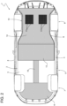
Figure 2 is a schematic view from below, with parts removed for clarity, of the car inFigure 1 ; -
Figure 3 is a schematic perspective view, with parts removed for clarity, of a detail of the car inFigure 1 ; -
Figure 4 is a schematic plan view of the detail infigure 3 , with parts removed for clarity; -
Figure 5 is a schematic perspective view, with parts removed for clarity, of a variant of the detail inFigure 3 ; -
Figure 6 is a schematic plan view, with parts removed for clarity, of the variant inFigure 5 ; and -
Figure 7 is a schematic view from below, with parts removed for clarity, of the variant inFigure 5 . - With reference to
Figures 1 and2 , reference number 1 indicates, as a whole, a car, in particular a sports car, comprising asupport frame 2 defining part of alower floor 3 of the car 1. - The car 1 also comprises a
passenger compartment 4 mounted on theframe 2 and projecting upwards from thefloor 3, and anaerodynamic bottom 5 partially fixed to theframe 2 and defining part of thefloor 3. - The
bottom 5 comprises afront bottom 6 fixed to theframe 2 in afront zone 7 of the car 1, arear bottom 8 fixed to theframe 2 in arear zone 9 of the car 1, and an elongatedcentral bottom 10 fixed to theframe 2 between thebottoms central zone 11 of the car 1. - The car 1 also comprises a known driving engine (not shown), which is mounted in the centre of the
rear zone 9 and is connected to theframe 2 by interposing a known elastic shock-absorbing device (not shown) so as to have at least one degree of freedom relative to theframe 2 during the normal operation of the car 1. - According to what is shown in
Figures 2 ,3, and 4 , therear bottom 8 comprises afront plate 12 and a rear, box-shaped body 13 arranged in succession along therear zone 9 of the car 1. - The
body 13 is delimited by alower wall 14 facing a road surface (not shown), and is configured to define apneumatic chamber 15, which communicates with the outside environment both via an openrear end 16 andmultiple openings 17 made through thewall 14. - The
chamber 15 defines part of apneumatic unit 18 comprising, in addition, in this case, a pair offans 19 mounted inside thechamber 15 at respective,multiple openings 17. - Each
fan 19 is a reversible fan that has a first operating mode, wherein thefan 19 is driven to blow an air flow F1 outside thechamber 15 through theopenings 17 and in the direction of the road surface (not shown), and a second operating mode, wherein thefan 19 is driven to suck part of an air flow F2 circulating below thefloor 3, from thefront zone 7 to therear zone 9, inside thechamber 15 during normal operation of the car 1. - The car 1 also comprises an
electronic control unit 20 configured to selectively control the operation of thefans 19 and, thus, the blowing of the air flow F1 and the suction of part of the air flow F2 as a function of an operating parameter, for example the speed, of the car 1 and/or of a geometrical parameter of a forward path (not shown) of the car 1. - According to a variant not shown, the
fans 19 are eliminated and replaced one with a blowing pneumatic device, in particular a fan, driven to blow the air flow F1 outside thechamber 15 in the direction of the road surface (not shown) and the other with a sucking pneumatic device, in particular a fan, driven to suck part of the air flow F2 inside thechamber 15. - The blowing of the air flow F1 and/or the suction of part of the air flow F2 modify the air flow F2 and, thus, the vertical aerodynamic load and the aerodynamics of the car 1.
- The variant shown in
Figures 5, 6, and 7 differs from what is shown in the previous figures solely due to the fact that, in it, therear bottom 8 is eliminated and replaced with arear bottom 21 comprising afront plate 22 and a rear, box-shaped body 23 arranged in succession along therear zone 9 of the car 1. - The
body 23 is delimited by alower wall 24 facing the road surface (not shown), and defines a closedpneumatic chamber 25, which communicates with the outside environment viamultiple openings 26 made through thewall 24. - The
chamber 25 defines part of apneumatic unit 27 comprising, in addition, in this case, a pair ofpneumatic devices 28 mounted outside thechamber 25. - Each
device 28 is a reversible pneumatic device that has a first operating mode, wherein thedevice 28 is driven to blow the air flow F1, firstly, through thechamber 25 and, then, through theopenings 26 in the direction of the road surface (not shown), and a second operating mode, wherein thedevice 28 is driven to suck part of the air flow F2, firstly, inside thechamber 25 and, then, through thedevice 28. - Alternatively, the
devices 28 are driven one with the first operating mode and the other with the second operating mode. - The
electronic control unit 20 is configured to selectively control the operation of thedevices 28 and, thus, the blowing of the air flow F1 and the suction of part of the air flow F2 as a function of an operating parameter, for example the speed, of the car 1 and/or of a geometrical parameter of a forward path (not shown) of the car 1. - The blowing of the air flow F1 and/or the suction of part of the air flow F2 modify the air flow F2 and, thus, the vertical aerodynamic load and the aerodynamics of the car 1.
- With reference to what is described above, it is also useful to specify that the blowing of the air flow F1 enables cleaning of the
lower walls rear bottoms
Claims (10)
- - A car comprising a support frame (2) defining part of a lower floor (3) of the car; a passenger compartment (4) projecting upwards from the lower floor (3); a driving engine to move the car; and an aerodynamic bottom (5), which is at least partly fixed to the support frame (2), defines part of the lower floor (3) and comprises, in turn, a rear bottom (8; 21) mounted in the area of a rear zone (9) of the car; and characterized in that the rear bottom (8; 21) is provided with a pneumatic unit (18; 27) configured to blow a first air flow (F1) in the direction of a road surface and/or to suck part of a second air flow (F2) flowing under the lower floor (3) during the normal operation of the car.
- - The car according to claim 1, wherein the pneumatic unit (18; 27) comprises at least one reversible pneumatic device (19; 28) configured both to blow the first air flow (F1) in the direction of the road surface and to suck part of the second air flow (F2).
- The car according to claim 1, wherein the pneumatic unit (18; 27) comprises a blowing pneumatic device (19; 28) to blow the first air flow (F1) and/or a sucking pneumatic device (19; 28) to suck part of the second air flow (F2).
- The car according to any one of the preceding claims, wherein the pneumatic unit (18; 27) comprises a pneumatic chamber (15; 25) obtained in the rear bottom (8; 21) and a plurality of openings (17; 26) obtained through a lower wall (14; 24) of the rear bottom (8; 21) in order to connect the pneumatic chamber (15; 25) to the outside under the lower floor (3).
- The car according to claim 4, wherein the pneumatic unit (18; 27) comprises at least one reversible pneumatic device (19; 28), which is configured both to blow the first air flow (F1) in the direction of the road surface and to suck part of the second air flow (F2).
- The car according to claim 5, wherein the pneumatic chamber (25) is closed and communicates with the outside only through said openings (26); the reversible pneumatic device (28) being mounted on the outside of the pneumatic chamber (25).
- The car according to claim 5, wherein the pneumatic chamber (15) is open in the area of a rear end (16) of its; the reversible pneumatic device (19) being mounted on the inside of the pneumatic chamber (15).
- The car according to claim 4, wherein the pneumatic unit (18; 27) comprises a blowing pneumatic device (19; 28) to blow the first air flow (F1) and/or a sucking pneumatic device (19; 28) to suck part of the second air flow (F2).
- The car according to claim 8, wherein the pneumatic chamber (25) is closed and communicates with the outside only through said openings (26); the blowing pneumatic device (28) and/or the sucking pneumatic device (28) being mounted on the outside of the pneumatic chamber (25).
- The car according to claim 8, wherein the pneumatic chamber (15) is open in the area of a rear end (16) of its; the blowing pneumatic device (19) and/or the sucking pneumatic device (19) being mounted on the inside of the pneumatic chamber (15).
Applications Claiming Priority (1)
| Application Number | Priority Date | Filing Date | Title |
|---|---|---|---|
| IT102022000019344A IT202200019344A1 (en) | 2022-09-21 | 2022-09-21 | CAR |
Publications (1)
| Publication Number | Publication Date |
|---|---|
| EP4342773A1 true EP4342773A1 (en) | 2024-03-27 |
Family
ID=84362602
Family Applications (1)
| Application Number | Title | Priority Date | Filing Date |
|---|---|---|---|
| EP23197905.5A Pending EP4342773A1 (en) | 2022-09-21 | 2023-09-18 | Car |
Country Status (5)
| Country | Link |
|---|---|
| US (1) | US12612120B2 (en) |
| EP (1) | EP4342773A1 (en) |
| JP (1) | JP2024045051A (en) |
| CN (1) | CN117734840A (en) |
| IT (1) | IT202200019344A1 (en) |
Families Citing this family (5)
| Publication number | Priority date | Publication date | Assignee | Title |
|---|---|---|---|---|
| USD1058462S1 (en) * | 2021-08-24 | 2025-01-21 | Dr. Ing. H.C. F. Porsche Aktiengesellschaft | Rear quarter panel for motor vehicle |
| USD1103046S1 (en) * | 2023-04-28 | 2025-11-25 | Aston Martin Lagonda Limited | Diffuser assembly for automobile or replica thereof |
| USD1120810S1 (en) | 2023-04-28 | 2026-03-31 | Aston Martin Lagonda Limited | Automobile or replica thereof |
| JP1765564S (en) * | 2023-08-08 | 2024-03-13 | automotive rear bumper | |
| USD1066191S1 (en) * | 2023-08-14 | 2025-03-11 | GM Global Technology Operations LLC | Vehicle rear fascia panel |
Citations (4)
| Publication number | Priority date | Publication date | Assignee | Title |
|---|---|---|---|---|
| JPH04339079A (en) * | 1991-05-13 | 1992-11-26 | Yamaha Motor Co Ltd | Device for improving aerodynamic characteristic of car |
| EP1919758A1 (en) * | 2005-08-09 | 2008-05-14 | Actiflow B.V. | Boundary layer suction system for a vehicle |
| EP2788248A1 (en) * | 2011-12-09 | 2014-10-15 | Toyota Jidosha Kabushiki Kaisha | Fluid control apparatus |
| US20180281876A1 (en) * | 2015-09-30 | 2018-10-04 | Compagnie Plastic Omnium | Aerodynamic System Comprising A Vortex Generator Supplied By Exhaust Gases |
Family Cites Families (3)
| Publication number | Priority date | Publication date | Assignee | Title |
|---|---|---|---|---|
| JP6168139B2 (en) * | 2013-02-20 | 2017-07-26 | トヨタ自動車株式会社 | Body structure |
| JP7429168B2 (en) * | 2020-07-30 | 2024-02-07 | 株式会社Subaru | rectifier |
| IT202300003864A1 (en) * | 2023-03-03 | 2024-09-03 | Ferrari Spa | AUTOMOBILE EQUIPPED WITH A PNEUMATIC UNIT ACTIVATED BY A GEARBOX |
-
2022
- 2022-09-21 IT IT102022000019344A patent/IT202200019344A1/en unknown
-
2023
- 2023-09-18 EP EP23197905.5A patent/EP4342773A1/en active Pending
- 2023-09-19 JP JP2023150659A patent/JP2024045051A/en active Pending
- 2023-09-20 US US18/470,496 patent/US12612120B2/en active Active
- 2023-09-21 CN CN202311225088.2A patent/CN117734840A/en active Pending
Patent Citations (4)
| Publication number | Priority date | Publication date | Assignee | Title |
|---|---|---|---|---|
| JPH04339079A (en) * | 1991-05-13 | 1992-11-26 | Yamaha Motor Co Ltd | Device for improving aerodynamic characteristic of car |
| EP1919758A1 (en) * | 2005-08-09 | 2008-05-14 | Actiflow B.V. | Boundary layer suction system for a vehicle |
| EP2788248A1 (en) * | 2011-12-09 | 2014-10-15 | Toyota Jidosha Kabushiki Kaisha | Fluid control apparatus |
| US20180281876A1 (en) * | 2015-09-30 | 2018-10-04 | Compagnie Plastic Omnium | Aerodynamic System Comprising A Vortex Generator Supplied By Exhaust Gases |
Also Published As
| Publication number | Publication date |
|---|---|
| JP2024045051A (en) | 2024-04-02 |
| US12612120B2 (en) | 2026-04-28 |
| IT202200019344A1 (en) | 2024-03-21 |
| CN117734840A (en) | 2024-03-22 |
| US20240092434A1 (en) | 2024-03-21 |
Similar Documents
| Publication | Publication Date | Title |
|---|---|---|
| EP4342773A1 (en) | Car | |
| EP4431375A1 (en) | Car provided with a pneumatic unit operated by a gearbox | |
| US10518631B2 (en) | Automotive grille | |
| EP1987982A1 (en) | Moving seat for vehicles | |
| JP2006505439A (en) | Automobile chassis and / or support structure | |
| CN104884328B (en) | Vehicle air conditioner and the rail truck with the vehicle air conditioner | |
| US11376928B2 (en) | Air register assembly | |
| CN109774423B (en) | Vehicle ventilation system | |
| EP1919758B1 (en) | Boundary layer suction system for a vehicle | |
| EP2788248B1 (en) | Fluid control apparatus | |
| US10933827B2 (en) | Duct | |
| SE1550642A1 (en) | Method and commercial vehicle including air flow redirector | |
| US9975579B2 (en) | Cowl structure | |
| US20240083522A1 (en) | Car | |
| KR20210077996A (en) | Manufacturing method of automobile vent duct mold | |
| JP2008230436A (en) | Automotive front structure | |
| KR102621914B1 (en) | Air amplification undercover | |
| CN107662651A (en) | Motor vehicles bumper beam and motor vehicles front portion or rear portion arrangement | |
| CN108583196B (en) | Defroster structure | |
| KR100613707B1 (en) | Vent duct of automobile and manufacturing mold thereof | |
| JP7068799B2 (en) | Blower for vehicles | |
| KR20210070629A (en) | Dash assembly of vehicle | |
| SE532307C2 (en) | Device for cooling an area behind a vehicle engine | |
| TH2101001520A (en) | air blowing device | |
| JP2023145900A (en) | Lower body structure |
Legal Events
| Date | Code | Title | Description |
|---|---|---|---|
| PUAI | Public reference made under article 153(3) epc to a published international application that has entered the european phase |
Free format text: ORIGINAL CODE: 0009012 |
|
| STAA | Information on the status of an ep patent application or granted ep patent |
Free format text: STATUS: THE APPLICATION HAS BEEN PUBLISHED |
|
| AK | Designated contracting states |
Kind code of ref document: A1 Designated state(s): AL AT BE BG CH CY CZ DE DK EE ES FI FR GB GR HR HU IE IS IT LI LT LU LV MC ME MK MT NL NO PL PT RO RS SE SI SK SM TR |
|
| STAA | Information on the status of an ep patent application or granted ep patent |
Free format text: STATUS: REQUEST FOR EXAMINATION WAS MADE |
|
| 17P | Request for examination filed |
Effective date: 20240917 |
|
| RBV | Designated contracting states (corrected) |
Designated state(s): AL AT BE BG CH CY CZ DE DK EE ES FI FR GB GR HR HU IE IS IT LI LT LU LV MC ME MK MT NL NO PL PT RO RS SE SI SK SM TR |