EP4342721A1 - On-board charger and electric vehicle - Google Patents
On-board charger and electric vehicle Download PDFInfo
- Publication number
- EP4342721A1 EP4342721A1 EP22874296.1A EP22874296A EP4342721A1 EP 4342721 A1 EP4342721 A1 EP 4342721A1 EP 22874296 A EP22874296 A EP 22874296A EP 4342721 A1 EP4342721 A1 EP 4342721A1
- Authority
- EP
- European Patent Office
- Prior art keywords
- phase
- voltage
- preset
- module
- difference
- Prior art date
- Legal status (The legal status is an assumption and is not a legal conclusion. Google has not performed a legal analysis and makes no representation as to the accuracy of the status listed.)
- Pending
Links
Images
Classifications
-
- B—PERFORMING OPERATIONS; TRANSPORTING
- B60—VEHICLES IN GENERAL
- B60L—PROPULSION OF ELECTRICALLY-PROPELLED VEHICLES; SUPPLYING ELECTRIC POWER FOR AUXILIARY EQUIPMENT OF ELECTRICALLY-PROPELLED VEHICLES; ELECTRODYNAMIC BRAKE SYSTEMS FOR VEHICLES IN GENERAL; MAGNETIC SUSPENSION OR LEVITATION FOR VEHICLES; MONITORING OPERATING VARIABLES OF ELECTRICALLY-PROPELLED VEHICLES; ELECTRIC SAFETY DEVICES FOR ELECTRICALLY-PROPELLED VEHICLES
- B60L53/00—Methods of charging batteries, specially adapted for electric vehicles; Charging stations or on-board charging equipment therefor; Exchange of energy storage elements in electric vehicles
- B60L53/20—Methods of charging batteries, specially adapted for electric vehicles; Charging stations or on-board charging equipment therefor; Exchange of energy storage elements in electric vehicles characterised by converters located in the vehicle
- B60L53/22—Constructional details or arrangements of charging converters specially adapted for charging electric vehicles
-
- H—ELECTRICITY
- H02—GENERATION; CONVERSION OR DISTRIBUTION OF ELECTRIC POWER
- H02J—ELECTRIC POWER NETWORKS; CIRCUIT ARRANGEMENTS OR SYSTEMS FOR SUPPLYING OR DISTRIBUTING ELECTRIC POWER; SYSTEMS FOR STORING ELECTRIC ENERGY
- H02J7/00—Circuit arrangements for charging or discharging batteries or for supplying loads from batteries
- H02J7/02—Circuit arrangements for charging or discharging batteries or for supplying loads from batteries for charging batteries from AC mains by converters
-
- B—PERFORMING OPERATIONS; TRANSPORTING
- B60—VEHICLES IN GENERAL
- B60L—PROPULSION OF ELECTRICALLY-PROPELLED VEHICLES; SUPPLYING ELECTRIC POWER FOR AUXILIARY EQUIPMENT OF ELECTRICALLY-PROPELLED VEHICLES; ELECTRODYNAMIC BRAKE SYSTEMS FOR VEHICLES IN GENERAL; MAGNETIC SUSPENSION OR LEVITATION FOR VEHICLES; MONITORING OPERATING VARIABLES OF ELECTRICALLY-PROPELLED VEHICLES; ELECTRIC SAFETY DEVICES FOR ELECTRICALLY-PROPELLED VEHICLES
- B60L3/00—Electric devices on electrically-propelled vehicles for safety purposes; Monitoring operating variables, e.g. speed, deceleration or energy consumption
-
- B—PERFORMING OPERATIONS; TRANSPORTING
- B60—VEHICLES IN GENERAL
- B60L—PROPULSION OF ELECTRICALLY-PROPELLED VEHICLES; SUPPLYING ELECTRIC POWER FOR AUXILIARY EQUIPMENT OF ELECTRICALLY-PROPELLED VEHICLES; ELECTRODYNAMIC BRAKE SYSTEMS FOR VEHICLES IN GENERAL; MAGNETIC SUSPENSION OR LEVITATION FOR VEHICLES; MONITORING OPERATING VARIABLES OF ELECTRICALLY-PROPELLED VEHICLES; ELECTRIC SAFETY DEVICES FOR ELECTRICALLY-PROPELLED VEHICLES
- B60L3/00—Electric devices on electrically-propelled vehicles for safety purposes; Monitoring operating variables, e.g. speed, deceleration or energy consumption
- B60L3/0023—Detecting, eliminating, remedying or compensating for drive train abnormalities, e.g. failures within the drive train
- B60L3/0046—Detecting, eliminating, remedying or compensating for drive train abnormalities, e.g. failures within the drive train relating to electric energy storage systems, e.g. batteries or capacitors
-
- B—PERFORMING OPERATIONS; TRANSPORTING
- B60—VEHICLES IN GENERAL
- B60L—PROPULSION OF ELECTRICALLY-PROPELLED VEHICLES; SUPPLYING ELECTRIC POWER FOR AUXILIARY EQUIPMENT OF ELECTRICALLY-PROPELLED VEHICLES; ELECTRODYNAMIC BRAKE SYSTEMS FOR VEHICLES IN GENERAL; MAGNETIC SUSPENSION OR LEVITATION FOR VEHICLES; MONITORING OPERATING VARIABLES OF ELECTRICALLY-PROPELLED VEHICLES; ELECTRIC SAFETY DEVICES FOR ELECTRICALLY-PROPELLED VEHICLES
- B60L53/00—Methods of charging batteries, specially adapted for electric vehicles; Charging stations or on-board charging equipment therefor; Exchange of energy storage elements in electric vehicles
- B60L53/10—Methods of charging batteries, specially adapted for electric vehicles; Charging stations or on-board charging equipment therefor; Exchange of energy storage elements in electric vehicles characterised by the energy transfer between the charging station and the vehicle
- B60L53/14—Conductive energy transfer
-
- B—PERFORMING OPERATIONS; TRANSPORTING
- B60—VEHICLES IN GENERAL
- B60L—PROPULSION OF ELECTRICALLY-PROPELLED VEHICLES; SUPPLYING ELECTRIC POWER FOR AUXILIARY EQUIPMENT OF ELECTRICALLY-PROPELLED VEHICLES; ELECTRODYNAMIC BRAKE SYSTEMS FOR VEHICLES IN GENERAL; MAGNETIC SUSPENSION OR LEVITATION FOR VEHICLES; MONITORING OPERATING VARIABLES OF ELECTRICALLY-PROPELLED VEHICLES; ELECTRIC SAFETY DEVICES FOR ELECTRICALLY-PROPELLED VEHICLES
- B60L53/00—Methods of charging batteries, specially adapted for electric vehicles; Charging stations or on-board charging equipment therefor; Exchange of energy storage elements in electric vehicles
- B60L53/60—Monitoring or controlling charging stations
- B60L53/62—Monitoring or controlling charging stations in response to charging parameters, e.g. current, voltage or electrical charge
-
- B—PERFORMING OPERATIONS; TRANSPORTING
- B60—VEHICLES IN GENERAL
- B60L—PROPULSION OF ELECTRICALLY-PROPELLED VEHICLES; SUPPLYING ELECTRIC POWER FOR AUXILIARY EQUIPMENT OF ELECTRICALLY-PROPELLED VEHICLES; ELECTRODYNAMIC BRAKE SYSTEMS FOR VEHICLES IN GENERAL; MAGNETIC SUSPENSION OR LEVITATION FOR VEHICLES; MONITORING OPERATING VARIABLES OF ELECTRICALLY-PROPELLED VEHICLES; ELECTRIC SAFETY DEVICES FOR ELECTRICALLY-PROPELLED VEHICLES
- B60L53/00—Methods of charging batteries, specially adapted for electric vehicles; Charging stations or on-board charging equipment therefor; Exchange of energy storage elements in electric vehicles
- B60L53/60—Monitoring or controlling charging stations
- B60L53/65—Monitoring or controlling charging stations involving identification of vehicles or their battery types
-
- B—PERFORMING OPERATIONS; TRANSPORTING
- B60—VEHICLES IN GENERAL
- B60L—PROPULSION OF ELECTRICALLY-PROPELLED VEHICLES; SUPPLYING ELECTRIC POWER FOR AUXILIARY EQUIPMENT OF ELECTRICALLY-PROPELLED VEHICLES; ELECTRODYNAMIC BRAKE SYSTEMS FOR VEHICLES IN GENERAL; MAGNETIC SUSPENSION OR LEVITATION FOR VEHICLES; MONITORING OPERATING VARIABLES OF ELECTRICALLY-PROPELLED VEHICLES; ELECTRIC SAFETY DEVICES FOR ELECTRICALLY-PROPELLED VEHICLES
- B60L58/00—Methods or circuit arrangements for monitoring or controlling batteries or fuel cells, specially adapted for electric vehicles
- B60L58/10—Methods or circuit arrangements for monitoring or controlling batteries or fuel cells, specially adapted for electric vehicles for monitoring or controlling batteries
- B60L58/12—Methods or circuit arrangements for monitoring or controlling batteries or fuel cells, specially adapted for electric vehicles for monitoring or controlling batteries responding to state of charge [SoC]
-
- B—PERFORMING OPERATIONS; TRANSPORTING
- B60—VEHICLES IN GENERAL
- B60L—PROPULSION OF ELECTRICALLY-PROPELLED VEHICLES; SUPPLYING ELECTRIC POWER FOR AUXILIARY EQUIPMENT OF ELECTRICALLY-PROPELLED VEHICLES; ELECTRODYNAMIC BRAKE SYSTEMS FOR VEHICLES IN GENERAL; MAGNETIC SUSPENSION OR LEVITATION FOR VEHICLES; MONITORING OPERATING VARIABLES OF ELECTRICALLY-PROPELLED VEHICLES; ELECTRIC SAFETY DEVICES FOR ELECTRICALLY-PROPELLED VEHICLES
- B60L58/00—Methods or circuit arrangements for monitoring or controlling batteries or fuel cells, specially adapted for electric vehicles
- B60L58/10—Methods or circuit arrangements for monitoring or controlling batteries or fuel cells, specially adapted for electric vehicles for monitoring or controlling batteries
- B60L58/18—Methods or circuit arrangements for monitoring or controlling batteries or fuel cells, specially adapted for electric vehicles for monitoring or controlling batteries of two or more battery modules
- B60L58/20—Methods or circuit arrangements for monitoring or controlling batteries or fuel cells, specially adapted for electric vehicles for monitoring or controlling batteries of two or more battery modules having different nominal voltages
-
- G—PHYSICS
- G01—MEASURING; TESTING
- G01R—MEASURING ELECTRIC VARIABLES; MEASURING MAGNETIC VARIABLES
- G01R31/00—Arrangements for testing electric properties; Arrangements for locating electric faults; Arrangements for electrical testing characterised by what is being tested not provided for elsewhere
- G01R31/36—Arrangements for testing, measuring or monitoring the electrical condition of accumulators or electric batteries, e.g. capacity or state of charge [SoC]
-
- G—PHYSICS
- G01—MEASURING; TESTING
- G01R—MEASURING ELECTRIC VARIABLES; MEASURING MAGNETIC VARIABLES
- G01R31/00—Arrangements for testing electric properties; Arrangements for locating electric faults; Arrangements for electrical testing characterised by what is being tested not provided for elsewhere
- G01R31/50—Testing of electric apparatus, lines, cables or components for short-circuits, continuity, leakage current or incorrect line connections
- G01R31/54—Testing for continuity
-
- H—ELECTRICITY
- H02—GENERATION; CONVERSION OR DISTRIBUTION OF ELECTRIC POWER
- H02J—ELECTRIC POWER NETWORKS; CIRCUIT ARRANGEMENTS OR SYSTEMS FOR SUPPLYING OR DISTRIBUTING ELECTRIC POWER; SYSTEMS FOR STORING ELECTRIC ENERGY
- H02J1/00—Circuit arrangements for DC mains or DC distribution networks
- H02J1/08—Three-wire DC power distribution systems; Systems having more than three wires
- H02J1/082—DC supplies with two or more different DC voltage levels
-
- H—ELECTRICITY
- H02—GENERATION; CONVERSION OR DISTRIBUTION OF ELECTRIC POWER
- H02J—ELECTRIC POWER NETWORKS; CIRCUIT ARRANGEMENTS OR SYSTEMS FOR SUPPLYING OR DISTRIBUTING ELECTRIC POWER; SYSTEMS FOR STORING ELECTRIC ENERGY
- H02J7/00—Circuit arrangements for charging or discharging batteries or for supplying loads from batteries
- H02J7/50—Circuit arrangements for charging or discharging batteries or for supplying loads from batteries acting upon multiple batteries simultaneously or sequentially
-
- H—ELECTRICITY
- H02—GENERATION; CONVERSION OR DISTRIBUTION OF ELECTRIC POWER
- H02J—ELECTRIC POWER NETWORKS; CIRCUIT ARRANGEMENTS OR SYSTEMS FOR SUPPLYING OR DISTRIBUTING ELECTRIC POWER; SYSTEMS FOR STORING ELECTRIC ENERGY
- H02J7/00—Circuit arrangements for charging or discharging batteries or for supplying loads from batteries
- H02J7/90—Regulation of charging or discharging current or voltage
- H02J7/96—Regulation of charging or discharging current or voltage in response to battery voltage
-
- B—PERFORMING OPERATIONS; TRANSPORTING
- B60—VEHICLES IN GENERAL
- B60L—PROPULSION OF ELECTRICALLY-PROPELLED VEHICLES; SUPPLYING ELECTRIC POWER FOR AUXILIARY EQUIPMENT OF ELECTRICALLY-PROPELLED VEHICLES; ELECTRODYNAMIC BRAKE SYSTEMS FOR VEHICLES IN GENERAL; MAGNETIC SUSPENSION OR LEVITATION FOR VEHICLES; MONITORING OPERATING VARIABLES OF ELECTRICALLY-PROPELLED VEHICLES; ELECTRIC SAFETY DEVICES FOR ELECTRICALLY-PROPELLED VEHICLES
- B60L2210/00—Converter types
- B60L2210/10—DC to DC converters
- B60L2210/12—Buck converters
-
- H—ELECTRICITY
- H02—GENERATION; CONVERSION OR DISTRIBUTION OF ELECTRIC POWER
- H02J—ELECTRIC POWER NETWORKS; CIRCUIT ARRANGEMENTS OR SYSTEMS FOR SUPPLYING OR DISTRIBUTING ELECTRIC POWER; SYSTEMS FOR STORING ELECTRIC ENERGY
- H02J2105/00—Networks for supplying or distributing electric power characterised by their spatial reach or by the load
- H02J2105/30—Networks for supplying or distributing electric power characterised by their spatial reach or by the load the load networks being external to vehicles, i.e. exchanging power with vehicles
- H02J2105/33—Networks for supplying or distributing electric power characterised by their spatial reach or by the load the load networks being external to vehicles, i.e. exchanging power with vehicles exchanging power with road vehicles
- H02J2105/37—Networks for supplying or distributing electric power characterised by their spatial reach or by the load the load networks being external to vehicles, i.e. exchanging power with vehicles exchanging power with road vehicles exchanging power with electric vehicles [EV] or with hybrid electric vehicles [HEV]
-
- H—ELECTRICITY
- H02—GENERATION; CONVERSION OR DISTRIBUTION OF ELECTRIC POWER
- H02J—ELECTRIC POWER NETWORKS; CIRCUIT ARRANGEMENTS OR SYSTEMS FOR SUPPLYING OR DISTRIBUTING ELECTRIC POWER; SYSTEMS FOR STORING ELECTRIC ENERGY
- H02J2207/00—Details of circuit arrangements for charging or discharging batteries or supplying loads from batteries
- H02J2207/20—Charging or discharging characterised by the power electronics converter
-
- Y—GENERAL TAGGING OF NEW TECHNOLOGICAL DEVELOPMENTS; GENERAL TAGGING OF CROSS-SECTIONAL TECHNOLOGIES SPANNING OVER SEVERAL SECTIONS OF THE IPC; TECHNICAL SUBJECTS COVERED BY FORMER USPC CROSS-REFERENCE ART COLLECTIONS [XRACs] AND DIGESTS
- Y02—TECHNOLOGIES OR APPLICATIONS FOR MITIGATION OR ADAPTATION AGAINST CLIMATE CHANGE
- Y02T—CLIMATE CHANGE MITIGATION TECHNOLOGIES RELATED TO TRANSPORTATION
- Y02T10/00—Road transport of goods or passengers
- Y02T10/60—Other road transportation technologies with climate change mitigation effect
- Y02T10/70—Energy storage systems for electromobility, e.g. batteries
-
- Y—GENERAL TAGGING OF NEW TECHNOLOGICAL DEVELOPMENTS; GENERAL TAGGING OF CROSS-SECTIONAL TECHNOLOGIES SPANNING OVER SEVERAL SECTIONS OF THE IPC; TECHNICAL SUBJECTS COVERED BY FORMER USPC CROSS-REFERENCE ART COLLECTIONS [XRACs] AND DIGESTS
- Y02—TECHNOLOGIES OR APPLICATIONS FOR MITIGATION OR ADAPTATION AGAINST CLIMATE CHANGE
- Y02T—CLIMATE CHANGE MITIGATION TECHNOLOGIES RELATED TO TRANSPORTATION
- Y02T10/00—Road transport of goods or passengers
- Y02T10/60—Other road transportation technologies with climate change mitigation effect
- Y02T10/7072—Electromobility specific charging systems or methods for batteries, ultracapacitors, supercapacitors or double-layer capacitors
-
- Y—GENERAL TAGGING OF NEW TECHNOLOGICAL DEVELOPMENTS; GENERAL TAGGING OF CROSS-SECTIONAL TECHNOLOGIES SPANNING OVER SEVERAL SECTIONS OF THE IPC; TECHNICAL SUBJECTS COVERED BY FORMER USPC CROSS-REFERENCE ART COLLECTIONS [XRACs] AND DIGESTS
- Y02—TECHNOLOGIES OR APPLICATIONS FOR MITIGATION OR ADAPTATION AGAINST CLIMATE CHANGE
- Y02T—CLIMATE CHANGE MITIGATION TECHNOLOGIES RELATED TO TRANSPORTATION
- Y02T90/00—Enabling technologies or technologies with a potential or indirect contribution to GHG emissions mitigation
- Y02T90/10—Technologies relating to charging of electric vehicles
- Y02T90/14—Plug-in electric vehicles
Definitions
- the present disclosure relates to the technical field of electric vehicles, and more specifically, to an on-board charger and an electric vehicle.
- a first purpose of the present disclosure is to provide an on-board charger.
- the on-board charger has advantages such as high disconnection detection accuracy.
- an embodiment of a first aspect of the present disclosure provides an on-board charger.
- the on-board charger includes:
- the microprocessor is configured to: obtain a first voltage and a current value of the first sampling point, and obtain a second voltage of the second sampling point; and mark the connection between the storage battery and the DC module as cut off and record a first difference between the second voltage and the first voltage when the first voltage is greater than the second voltage and the current value is less than a preset current threshold.
- the first sampling point is arranged between the DC module and the storage battery
- the second sampling point is arranged between the storage battery and the microprocessor. Therefore, in the present disclosure, it is determined whether the connection between the storage battery and the DC module is cut off based on a result of comparison between voltage sampling information of the first sampling point and voltage sampling information of the second sampling point and current sampling information of the first sampling point. In this way, disconnection detection accuracy is improved, and long-term continuous travelling in a case that the connection between the storage battery and the DC module of the electric vehicle is cut off is avoided, thereby improving travelling safety and reducing travelling risks.
- a second purpose of the present disclosure is to provide an electric vehicle, which includes the on-board charger provided in the first purpose.
- an embodiment of the present disclosure provides an on-board charger.
- the on-board charger includes a DC module 2 and a microprocessor 4.
- a first end of the DC module 2 is connected with a power battery 1.
- a second end of the DC module 2 is connected with a storage battery 3.
- a first sampling point A1 is arranged between the storage battery 3 and the DC module 2.
- the microprocessor 4 is connected with the storage battery 3.
- a second sampling point A2 is arranged between the microprocessor 4 and the storage battery 3.
- the microprocessor 4 is connected with the first sampling point A1 and the second sampling point A2.
- FIG. 1 a low-voltage control circuit of the on-board charger is described through arrows in the present disclosure.
- the microprocessor 4 is configured to: obtain a first voltage and a current value of the first sampling point, and obtain a second voltage of the second sampling point; and mark the connection between the storage battery 3 and the DC module 2 as cut off and record a first difference between the second voltage and the first voltage when the first voltage is greater than the second voltage and the current value is less than a preset current threshold.
- the first sampling point A1 is arranged between the DC module 2 and the storage battery 3, and the second sampling point A2 is arranged between the storage battery 3 and the microprocessor 4. Therefore, in the present disclosure, it is determined whether the connection between the storage battery 3 and the DC module 2 is cut off based on a result of comparison between voltage sampling information of the first sampling point A1 and voltage sampling information of the second sampling point A2 and current sampling information of the first sampling point. In this way, disconnection detection accuracy is improved, and long-term continuous travelling in a case that the connection between the storage battery 3 and the DC module 2 of the electric vehicle is cut off is avoided, thereby improving travelling safety and reducing travelling risks.
- the microprocessor 4 is further configured to: control the DC module 2 to increase an output voltage of the DC module 2 when the connection between the storage battery 3 and the DC module 2 is marked as cut off; reobtain a third voltage of the first sampling point A1, reobtain a fourth voltage of the second sampling point A2, and obtain a second difference between the fourth voltage and the third voltage; determine that the connection between the storage battery 3 and the DC module 2 is cut off when a difference between the second difference and the first difference is greater than or equal to a preset threshold; and determine that the connection between the storage battery 3 and the DC module 2 is not cut off when the difference between the second difference and the first difference is less than the preset threshold.
- the DC module 2 is controlled to increase the output voltage of DC module 2, and it is determined whether the connection between the DC module 2 and the storage battery 3 is cut off based on re-sampled voltage sampling information.
- the difference between the second difference and the first difference is less than the preset threshold, it is determined that the connection between the DC module 2 and the storage battery 3 is not cut off, which avoids erroneous disconnection determination.
- the difference between the second difference and the first difference is greater than or equal to the preset threshold, that is, when the voltage sampling information of the first sampling point A1 increases as a voltage of the DC module increases, but the voltage sampling information of the second sampling point decreases as the power supply to the outside proceeds, which results in a relatively large difference between the second difference and the first difference, reliability of determination of the disconnection between the storage battery 3 and the DC module 2 is improved.
- the on-board charger further includes a PFC module 10 and a DC/DC module 11.
- a first end of the PFC module 10 is connected with a charging interface 12.
- a second end of the PFC module 10 is connected with a first end of the DC/DC module 11.
- a second end of the DC/DC module 11 is connected with the power battery 1 and the first end of the DC module 2.
- the charging interface 12 includes three L terminals and an N terminal.
- the PFC module 10 includes three inductors, three-phase high-frequency bridge arms, and one-phase power-frequency bridge arm. A first end of each of the inductors is connected with one of the L terminals. The other end is connected with a midpoint of one-phase high-frequency bridge arm.
- the N terminal is connected with a midpoint of the power-frequency bridge arm. Top ends of the three-phase high-frequency bridge arms and the one-phase power-frequency bridge arm are jointly connected to form a first confluent end. Bottom ends of the three-phase high-frequency bridge arms and the one-phase power-frequency bridge arm are jointly connected to form a second confluent end.
- the first end of the DC/DC module 11 is connected with the first confluent end and the second confluent end.
- the second end of the DC/DC module 11 is connected with the first end of the DC module 2 and the power battery 1.
- the three L terminals include an L1 terminal, an L2 terminal, and an L3 terminal.
- the three inductors include a first inductor L1, a second inductor L2, and a third inductor L3.
- the three-phase high-frequency bridge arms include a first phase high-frequency bridge arm (Q1+Q2), a second phase high-frequency bridge arm (Q3+Q4), and a third phase high-frequency bridge arm (Q5+Q6).
- a first end of the first inductor L1 is connected with the L1 terminal.
- a second end of the first inductor L1 is connected with a midpoint of the first phase high-frequency bridge arm.
- a first end of the second inductor L2 is connected with the L2 terminal.
- a second end of the second inductor L2 is connected with a midpoint of the second phase high-frequency bridge arm.
- a first end of the third inductor L3 is connected with the L3 terminal.
- a second end of the third inductor L3 is connected with a midpoint of the third phase high-frequency bridge arm.
- the N terminal is connected with the midpoint of the one-phase power-frequency bridge arm (Q7+Q8).
- the top ends of the three-phase high-frequency bridge arms and the one-phase power-frequency bridge arm are jointly connected to form the first confluent end.
- the bottom ends of the three-phase high-frequency bridge arms and the one-phase power-frequency bridge arm are jointly connected to form the second confluent end.
- the microprocessor 4 is further configured to: obtain a first phase and a first effective voltage corresponding to the first phase bridge arm, a second phase and a second effective voltage corresponding to the second phase bridge arm, and a third phase and a third effective voltage corresponding to the third phase bridge arm;
- both single-phase charging and three-phase charging are allowed.
- the single-phase/three-phase charging mode is identified with reference to the phase difference and the effective voltage, so that identification may be performed in another identification manner when identification through only the phase difference or only the effective voltage is inaccurate, thereby improving identification accuracy and reducing an erroneous determination rate.
- the determination that the external power supply is the single-phase power supply or the three-phase power supply based on the first phase difference, the second phase difference, the third phase difference, the first effective voltage, the second effective voltage, and the third effective voltage includes at least the following implementations:
- identification of single phase and three phase is performed first through the phase difference.
- identification of single phase and three phase is performed through the effective voltage.
- identification of single phase and three phase is performed first through the effective voltage.
- identification of single phase and three phase is performed through the phase difference.
- identification of single phase is performed first through the phase difference.
- identification of single phase and three phase is performed through the effective voltage.
- identification of three phase is performed first through the phase difference.
- identification of single phase and three phase is performed through the effective voltage.
- identification of single phase is performed first through the effective voltage.
- identification of single phase and three phase is performed through the phase difference.
- identification of three phase is performed first through the effective voltage.
- identification of single phase and three phase is performed through the phase difference.
- the microprocessor 4 is further configured to: determine whether the first phase difference, the second phase difference, and the third phase difference all satisfy a preset charging mode determination condition; and determine that the external power supply is the single-phase power supply or the three-phase power supply based on the first effective voltage, the second effective voltage, and the third effective voltage when any of the first phase difference, the second phase difference, and the third phase difference does not satisfy the preset charging mode determination condition.
- the preset charging mode determination condition includes a preset three-phase charging determination condition; and the preset three-phase charging determination condition is that the first phase difference, the second phase difference, and the third phase difference all fall within a preset phase range.
- the preset phase range may be preset or may be set in real time as required by a user.
- the preset phase range may be (105°, 125°).
- the preset charging mode determination condition includes a preset single-phase charging determination condition; and the preset single-phase charging determination condition is that the first phase difference, the second phase difference, and the third phase difference are all less than a preset phase threshold.
- the preset phase threshold may be preset or may be set in real time as required by a user.
- the preset phase threshold may be 10°.
- the identification is performed first through the phase difference and then through the effective voltage. Therefore, during identification through the phase difference, if the phase difference does not satisfy the preset three-phase charging determination condition, an operation of "determining whether the phase difference satisfies the preset single-phase charging determination condition" is directly abandoned, to avoid repeated invalid operations when the identification through the phase difference fails (for example, a phase loss or abnormal phase detection occurs), which simplifies the identification process, thereby improving an identification rate.
- an operation of "determining whether the phase difference satisfies the preset three-phase charging determination condition" is directly abandoned, to avoid repeated invalid operations when the identification through the phase difference fails (for example, a phase loss or abnormal phase detection occurs), which simplifies the identification process, thereby improving the identification rate.
- the microprocessor 4 is further configured to: determine whether the preset single-phase charging determination condition or the preset three-phase charging determination condition is satisfied based on the first effective voltage, the second effective voltage, and the third effective voltage; determine that the external power supply is the single-phase power supply if it is determined that the preset single-phase charging determination condition is satisfied; and determine that the external power supply is the three-phase power supply if it is determined that the preset three-phase charging determination condition is satisfied.
- the preset three-phase charging determination condition is: the first effective voltage > the second effective voltage > the third effective voltage > a first preset voltage threshold.
- the first preset voltage threshold may be preset or may be set in real time as required by a user.
- the first preset voltage threshold may be 150 V
- the preset single-phase charging determination condition is: the first effective voltage > the second effective voltage > the third effective voltage and the second effective voltage ⁇ a second preset voltage threshold.
- the second preset voltage threshold may be preset or may be set in real time as required by a user.
- the second preset voltage threshold may be 20 V
- the identification is performed first through the effective voltage and then through the phase difference. Therefore, during the identification through the effective voltage, if the effective voltage does not satisfy the preset single-phase charging determination condition, an operation of "determining whether the effective voltage satisfies the preset three-phase charging determination condition" is directly abandoned, to avoid repeated invalid operations when the identification through the effective voltage fails (for example, a detected effective voltage is abnormal as a result of signal interference from hardware), which simplifies the identification process, thereby improving the identification rate.
- an operation of "determining whether the effective voltage satisfies the preset single-phase charging determination condition" is directly abandoned, to avoid repeated invalid operations when the identification through the effective voltage fails (for example, a detected effective voltage is abnormal as a result of signal interference from hardware), which simplifies the identification process, thereby improving the identification rate.
- a second aspect of the present disclosure provides an electric vehicle, which includes the on-board charger described in the embodiment of the first aspect.
- orientation or position relationships indicated by terms such as “center”, “longitudinal”, “transverse”, “length”, “width”, “thickness”, “upper”, “lower”, “front”, “rear”, “left”, “right”, “vertical”, “horizontal”, “top”, “bottom”, “interior”, “exterior”, “axial”, and “circumferential” are based on orientation or position relationships shown in the drawings, are merely used to facilitate the description of the present disclosure and simplify the description, instead of indicating or implying that the indicated apparatus or element needs to have particular orientations or be constructed and operated in particular orientations, and therefore cannot be construed as a limitation on the present disclosure.
- connection may be a fixed connection, a detachable connection, or an integral connection; or the connection may be a direct connection, an indirect connection through an intermediary, or internal communication between two elements.
Landscapes
- Engineering & Computer Science (AREA)
- Power Engineering (AREA)
- Transportation (AREA)
- Mechanical Engineering (AREA)
- Life Sciences & Earth Sciences (AREA)
- Sustainable Development (AREA)
- Sustainable Energy (AREA)
- Physics & Mathematics (AREA)
- General Physics & Mathematics (AREA)
- Charge And Discharge Circuits For Batteries Or The Like (AREA)
Abstract
Description
- The present disclosure claims priority to
Chinese Patent Application No. 202111157823.1, entitled "ON-BOARD CHARGER AND ELECTRIC VEHICLE" and filed on September 29, 2021 - The present disclosure relates to the technical field of electric vehicles, and more specifically, to an on-board charger and an electric vehicle.
- As technologies develop, environmentally friendly and energy-saving electric vehicles are gradually replacing fuel vehicles. However, electric vehicles have some problems in popularization. If disconnection between a DC module configured to charge a storage battery and the storage battery is not detected in time, but the storage battery needs to continuously supply power to the outside, under voltage of the storage battery during travelling may be caused, resulting in low travelling safety and high travelling risks.
- The present disclosure is intended to resolve at least one of the technical problems in the related art. A first purpose of the present disclosure is to provide an on-board charger. The on-board charger has advantages such as high disconnection detection accuracy.
- In order to achieve the above purpose, an embodiment of a first aspect of the present disclosure provides an on-board charger. The on-board charger includes:
- a DC module, a first end of the DC module being connected with a power battery, a second end of the DC module being connected with a storage battery, and a first sampling point being arranged between the storage battery and the DC module; and
- a microprocessor, the microprocessor being connected with the storage battery, a second sampling point being arranged between the microprocessor and the storage battery, and the microprocessor being connected with the first sampling point and the second sampling point.
- The microprocessor is configured to: obtain a first voltage and a current value of the first sampling point, and obtain a second voltage of the second sampling point; and
mark the connection between the storage battery and the DC module as cut off and record a first difference between the second voltage and the first voltage when the first voltage is greater than the second voltage and the current value is less than a preset current threshold. - In the present disclosure, the first sampling point is arranged between the DC module and the storage battery, and the second sampling point is arranged between the storage battery and the microprocessor. Therefore, in the present disclosure, it is determined whether the connection between the storage battery and the DC module is cut off based on a result of comparison between voltage sampling information of the first sampling point and voltage sampling information of the second sampling point and current sampling information of the first sampling point. In this way, disconnection detection accuracy is improved, and long-term continuous travelling in a case that the connection between the storage battery and the DC module of the electric vehicle is cut off is avoided, thereby improving travelling safety and reducing travelling risks.
- A second purpose of the present disclosure is to provide an electric vehicle, which includes the on-board charger provided in the first purpose.
- Additional aspects and advantages of the present disclosure will be given in the following description, some of which will become apparent from the following description or may be learned from practices of the present disclosure.
- The above and/or additional aspects and advantages of the present disclosure will become apparent and comprehensible from the following descriptions of embodiments made with reference to the following drawings.
-
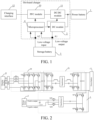
FIG. 1 is a schematic diagram of a framework structure of an on-board charger according to an embodiment of the present disclosure. -
FIG. 2 is a schematic diagram of a topology of the on-board charger according to an embodiment of the present disclosure. - Embodiments of the present disclosure are described in detail below, and the embodiments described with reference to drawings are exemplary.
- As shown in
FIG. 1 , an embodiment of the present disclosure provides an on-board charger. The on-board charger includes aDC module 2 and amicroprocessor 4. A first end of theDC module 2 is connected with apower battery 1. A second end of theDC module 2 is connected with astorage battery 3. A first sampling point A1 is arranged between thestorage battery 3 and theDC module 2. Themicroprocessor 4 is connected with thestorage battery 3. A second sampling point A2 is arranged between themicroprocessor 4 and thestorage battery 3. Themicroprocessor 4 is connected with the first sampling point A1 and the second sampling point A2. - It should be noted that, in
FIG. 1 , a low-voltage control circuit of the on-board charger is described through arrows in the present disclosure. - The
microprocessor 4 is configured to: obtain a first voltage and a current value of the first sampling point, and obtain a second voltage of the second sampling point; and mark the connection between thestorage battery 3 and theDC module 2 as cut off and record a first difference between the second voltage and the first voltage when the first voltage is greater than the second voltage and the current value is less than a preset current threshold. - In the present disclosure, the first sampling point A1 is arranged between the
DC module 2 and thestorage battery 3, and the second sampling point A2 is arranged between thestorage battery 3 and themicroprocessor 4. Therefore, in the present disclosure, it is determined whether the connection between thestorage battery 3 and theDC module 2 is cut off based on a result of comparison between voltage sampling information of the first sampling point A1 and voltage sampling information of the second sampling point A2 and current sampling information of the first sampling point. In this way, disconnection detection accuracy is improved, and long-term continuous travelling in a case that the connection between thestorage battery 3 and theDC module 2 of the electric vehicle is cut off is avoided, thereby improving travelling safety and reducing travelling risks. - In order to further improve the disconnection determination accuracy, based on this embodiment, in other embodiments, the
microprocessor 4 is further configured to:
control theDC module 2 to increase an output voltage of theDC module 2 when the connection between thestorage battery 3 and theDC module 2 is marked as cut off; reobtain a third voltage of the first sampling point A1, reobtain a fourth voltage of the second sampling point A2, and obtain a second difference between the fourth voltage and the third voltage; determine that the connection between thestorage battery 3 and theDC module 2 is cut off when a difference between the second difference and the first difference is greater than or equal to a preset threshold; and determine that the connection between thestorage battery 3 and theDC module 2 is not cut off when the difference between the second difference and the first difference is less than the preset threshold. - In this embodiment, the
DC module 2 is controlled to increase the output voltage ofDC module 2, and it is determined whether the connection between theDC module 2 and thestorage battery 3 is cut off based on re-sampled voltage sampling information. When the difference between the second difference and the first difference is less than the preset threshold, it is determined that the connection between theDC module 2 and thestorage battery 3 is not cut off, which avoids erroneous disconnection determination. That is to say, erroneous determination of disconnection between theDC module 2 and thestorage battery 3 in a case that an actual power supply current is very small and a sampling voltage of the second sampling point is less than a sampling voltage of the first sampling point as a result of a high impedance of a power supply circuit is avoided, thereby further improving the disconnection detection accuracy. In addition, when the difference between the second difference and the first difference is greater than or equal to the preset threshold, that is, when the voltage sampling information of the first sampling point A1 increases as a voltage of the DC module increases, but the voltage sampling information of the second sampling point decreases as the power supply to the outside proceeds, which results in a relatively large difference between the second difference and the first difference, reliability of determination of the disconnection between thestorage battery 3 and theDC module 2 is improved. - Based on this embodiment, in other embodiments, the on-board charger further includes a
PFC module 10 and a DC/DC module 11. A first end of thePFC module 10 is connected with acharging interface 12. A second end of thePFC module 10 is connected with a first end of the DC/DC module 11. A second end of the DC/DC module 11 is connected with thepower battery 1 and the first end of theDC module 2. - Referring to
FIG. 2 , thecharging interface 12 includes three L terminals and an N terminal. ThePFC module 10 includes three inductors, three-phase high-frequency bridge arms, and one-phase power-frequency bridge arm. A first end of each of the inductors is connected with one of the L terminals. The other end is connected with a midpoint of one-phase high-frequency bridge arm. The N terminal is connected with a midpoint of the power-frequency bridge arm. Top ends of the three-phase high-frequency bridge arms and the one-phase power-frequency bridge arm are jointly connected to form a first confluent end. Bottom ends of the three-phase high-frequency bridge arms and the one-phase power-frequency bridge arm are jointly connected to form a second confluent end. The first end of the DC/DC module 11 is connected with the first confluent end and the second confluent end. The second end of the DC/DC module 11 is connected with the first end of theDC module 2 and thepower battery 1. - Specifically, the three L terminals include an L1 terminal, an L2 terminal, and an L3 terminal. The three inductors include a first inductor L1, a second inductor L2, and a third inductor L3. The three-phase high-frequency bridge arms include a first phase high-frequency bridge arm (Q1+Q2), a second phase high-frequency bridge arm (Q3+Q4), and a third phase high-frequency bridge arm (Q5+Q6). A first end of the first inductor L1 is connected with the L1 terminal. A second end of the first inductor L1 is connected with a midpoint of the first phase high-frequency bridge arm. A first end of the second inductor L2 is connected with the L2 terminal. A second end of the second inductor L2 is connected with a midpoint of the second phase high-frequency bridge arm.
- A first end of the third inductor L3 is connected with the L3 terminal. A second end of the third inductor L3 is connected with a midpoint of the third phase high-frequency bridge arm. The N terminal is connected with the midpoint of the one-phase power-frequency bridge arm (Q7+Q8). The top ends of the three-phase high-frequency bridge arms and the one-phase power-frequency bridge arm are jointly connected to form the first confluent end. The bottom ends of the three-phase high-frequency bridge arms and the one-phase power-frequency bridge arm are jointly connected to form the second confluent end.
- The
microprocessor 4 is further configured to: obtain a first phase and a first effective voltage corresponding to the first phase bridge arm, a second phase and a second effective voltage corresponding to the second phase bridge arm, and a third phase and a third effective voltage corresponding to the third phase bridge arm; - obtain a first phase difference between the first phase and the second phase, a second phase difference between the second phase and the third phase, and a third phase difference between the third phase and the first phase;
- determine that an external power supply is a single-phase power supply or a three-phase power supply based on the first phase difference, the second phase difference, the third phase difference, the first effective voltage, the second effective voltage, and the third effective voltage;
- control a single-phase charging mode to be enabled if it is determined that the external power supply is the single-phase power supply; and
- control a three-phase charging mode to be enabled if it is determined that the external power supply is the three-phase power supply.
- In this embodiment, both single-phase charging and three-phase charging are allowed. In addition, in the related art, in case of identification through only a phase difference, if phase detection is abnormal, erroneous determination occurs. Alternatively, in case of identification through only an effective voltage, if an obtained effective voltage is subject to interference, erroneous determination is caused. Therefore, in this embodiment, the single-phase/three-phase charging mode is identified with reference to the phase difference and the effective voltage, so that identification may be performed in another identification manner when identification through only the phase difference or only the effective voltage is inaccurate, thereby improving identification accuracy and reducing an erroneous determination rate.
- In the above embodiment, the determination that the external power supply is the single-phase power supply or the three-phase power supply based on the first phase difference, the second phase difference, the third phase difference, the first effective voltage, the second effective voltage, and the third effective voltage includes at least the following implementations:
- (1) Identification of single phase and three phase is performed first through the phase difference and then through the effective voltage.
- Specifically, identification of single phase and three phase is performed first through the phase difference. When neither single-phase charging nor three-phase charging is identified through the phase difference, identification of single phase and three phase is performed through the effective voltage.
- (2) Identification of single phase and three phase is performed first through the effective voltage and then through the phase difference.
- Specifically, identification of single phase and three phase is performed first through the effective voltage. When neither single-phase charging nor three-phase charging is identified through the effective voltage, identification of single phase and three phase is performed through the phase difference.
- (3) Identification of single phase or three phase is performed first through the phase difference and then through the effective voltage.
- Specifically, identification of single phase is performed first through the phase difference. When single-phase charging is not identified through the phase difference, identification of single phase and three phase is performed through the effective voltage.
- In addition, identification of three phase is performed first through the phase difference. When three-phase charging is not identified through the phase difference, identification of single phase and three phase is performed through the effective voltage.
- (4) Identification of single phase or three phase is performed first through the effective voltage and then through the phase difference.
- Specifically, identification of single phase is performed first through the effective voltage. When single-phase charging is not identified through the effective voltage, identification of single phase and three phase is performed through the phase difference.
- In addition, identification of three phase is performed first through the effective voltage. When three-phase charging is not identified through the effective voltage, identification of single phase and three phase is performed through the phase difference.
- Based on this embodiment, in other embodiments,
- The
microprocessor 4 is further configured to:
determine whether the first phase difference, the second phase difference, and the third phase difference all satisfy a preset charging mode determination condition; and determine that the external power supply is the single-phase power supply or the three-phase power supply based on the first effective voltage, the second effective voltage, and the third effective voltage when any of the first phase difference, the second phase difference, and the third phase difference does not satisfy the preset charging mode determination condition. - In this embodiment, the preset charging mode determination condition includes a preset three-phase charging determination condition; and the preset three-phase charging determination condition is that the first phase difference, the second phase difference, and the third phase difference all fall within a preset phase range.
- In order to provide a more detailed description of the technical solutions of the present disclosure, the preset phase range may be preset or may be set in real time as required by a user. Exemplarily, the preset phase range may be (105°, 125°).
- In addition, in this embodiment, the preset charging mode determination condition includes a preset single-phase charging determination condition; and the preset single-phase charging determination condition is that the first phase difference, the second phase difference, and the third phase difference are all less than a preset phase threshold.
- In order to provide a more detailed description of the technical solutions of the present disclosure, the preset phase threshold may be preset or may be set in real time as required by a user. Exemplarily, the preset phase threshold may be 10°.
- During the identification of the single-phase/three-phase charging mode in this embodiment, the identification is performed first through the phase difference and then through the effective voltage. Therefore, during identification through the phase difference, if the phase difference does not satisfy the preset three-phase charging determination condition, an operation of "determining whether the phase difference satisfies the preset single-phase charging determination condition" is directly abandoned, to avoid repeated invalid operations when the identification through the phase difference fails (for example, a phase loss or abnormal phase detection occurs), which simplifies the identification process, thereby improving an identification rate.
- In addition, based on this embodiment, in other embodiments, during the identification through the phase difference, if the phase difference does not satisfy the preset single-phase charging determination condition, an operation of "determining whether the phase difference satisfies the preset three-phase charging determination condition" is directly abandoned, to avoid repeated invalid operations when the identification through the phase difference fails (for example, a phase loss or abnormal phase detection occurs), which simplifies the identification process, thereby improving the identification rate.
- In addition, based on this embodiment, in other embodiments, the
microprocessor 4 is further configured to:
determine whether the preset single-phase charging determination condition or the preset three-phase charging determination condition is satisfied based on the first effective voltage, the second effective voltage, and the third effective voltage; determine that the external power supply is the single-phase power supply if it is determined that the preset single-phase charging determination condition is satisfied; and determine that the external power supply is the three-phase power supply if it is determined that the preset three-phase charging determination condition is satisfied. - In this embodiment, the preset three-phase charging determination condition is: the first effective voltage > the second effective voltage > the third effective voltage > a first preset voltage threshold.
- In order to provide a more detailed description of the technical solutions of the present disclosure, the first preset voltage threshold may be preset or may be set in real time as required by a user. Exemplarily, the first preset voltage threshold may be 150 V
- In addition, in this embodiment, the preset single-phase charging determination condition is: the first effective voltage > the second effective voltage > the third effective voltage and the second effective voltage < a second preset voltage threshold.
- In order to provide a more detailed description of the technical solutions of the present disclosure, the second preset voltage threshold may be preset or may be set in real time as required by a user. Exemplarily, the second preset voltage threshold may be 20 V
- During the identification of the single-phase/three-phase charging mode in this embodiment, the identification is performed first through the effective voltage and then through the phase difference. Therefore, during the identification through the effective voltage, if the effective voltage does not satisfy the preset single-phase charging determination condition, an operation of "determining whether the effective voltage satisfies the preset three-phase charging determination condition" is directly abandoned, to avoid repeated invalid operations when the identification through the effective voltage fails (for example, a detected effective voltage is abnormal as a result of signal interference from hardware), which simplifies the identification process, thereby improving the identification rate.
- In addition, during the identification through the phase difference, if the effective voltage does not satisfy the preset three-phase charging determination condition, an operation of "determining whether the effective voltage satisfies the preset single-phase charging determination condition" is directly abandoned, to avoid repeated invalid operations when the identification through the effective voltage fails (for example, a detected effective voltage is abnormal as a result of signal interference from hardware), which simplifies the identification process, thereby improving the identification rate.
- A second aspect of the present disclosure provides an electric vehicle, which includes the on-board charger described in the embodiment of the first aspect.
- Specific principles and implementations of the on-board charger of the electric vehicle provided in this embodiment of the present disclosure are similar to those in the above embodiment of the first aspect, and therefore the details are not described herein.
- In the description of the present disclosure, it is to be understood that orientation or position relationships indicated by terms such as "center", "longitudinal", "transverse", "length", "width", "thickness", "upper", "lower", "front", "rear", "left", "right", "vertical", "horizontal", "top", "bottom", "interior", "exterior", "axial", and "circumferential" are based on orientation or position relationships shown in the drawings, are merely used to facilitate the description of the present disclosure and simplify the description, instead of indicating or implying that the indicated apparatus or element needs to have particular orientations or be constructed and operated in particular orientations, and therefore cannot be construed as a limitation on the present disclosure.
- In the description of the present disclosure, it should be noted that, unless otherwise explicitly specified or defined, the terms such as "mount", "connect", and "connection" should be understood in a broad sense. For example, the connection may be a fixed connection, a detachable connection, or an integral connection; or the connection may be a direct connection, an indirect connection through an intermediary, or internal communication between two elements. A person of ordinary skill in the art may understand the specific meanings of the above terms in the present disclosure according to specific situations.
- In the description of this specification, the description of the reference terms such as "an embodiment", "some embodiments", "exemplary embodiments", "example", "specific example", or "some examples" means that the specific features, structures, materials or characteristics described with reference to the embodiment or example are included in at least one embodiment or example of the present disclosure. In the present disclosure, exemplary descriptions of the above terms do not necessarily refer to the same embodiment or example.
- Although the embodiments of the present disclosure have been shown and described, a person of ordinary skill in the art should understand that various changes, modifications, replacements, and variations may be made to the embodiments without departing from the principles and spirit of the present disclosure, and the scope of the present disclosure is as defined by the appended claims and their equivalents.
Claims (10)
- An on-board charger, comprising:a DC module, a first end of the DC module being connected with a power battery, a second end of the DC module being connected with a storage battery, and a first sampling point being arranged between the storage battery and the DC module; anda microprocessor, the microprocessor being connected with the storage battery, a second sampling point being arranged between the microprocessor and the storage battery, and the microprocessor being connected with the first sampling point and the second sampling point; and
the microprocessor being configured to: obtain a first voltage and a current value of the first sampling point, and obtain a second voltage of the second sampling point; andmark the connection between the storage battery and the DC module as cut off and record a first difference between the second voltage and the first voltage when the first voltage is greater than the second voltage and the current value is less than a preset current threshold. - The on-board charger according to claim 1, wherein the microprocessor is further configured to:control the DC module to increase an output voltage of the DC module when the connection between the storage battery and the DC module is marked as cut off;reobtain a third voltage of the first sampling point, reobtain a fourth voltage of the second sampling point, and obtain a second difference between the fourth voltage and the third voltage;determine that the connection between the storage battery and the DC module is cut off when a difference between the second difference and the first difference is greater than or equal to a preset threshold; anddetermine that the connection between the storage battery and the DC module is not cut off when the difference between the second difference and the first difference is less than the preset threshold.
- The on-board charger according to claim 1 or 2, further comprising:a PFC module, the PFC module comprising three inductors, three-phase high-frequency bridge arms, and one-phase power-frequency bridge arm, the PFC module being connected with a charging interface, the charging interface comprising three L terminals and an N terminal, a first end of each of the inductors being connected with one of the L terminals, the other end being connected with a midpoint of one-phase high-frequency bridge arm, the N terminal being connected with a midpoint of the power-frequency bridge arm, top ends of the three-phase high-frequency bridge arms and the one-phase power-frequency bridge arm being jointly connected to form a first confluent end, and bottom ends of the three-phase high-frequency bridge arms and the one-phase power-frequency bridge arm being jointly connected to form a second confluent end; anda DC/DC module, a first end of the DC/DC module being connected with the first confluent end and the second confluent end, and a second end of the DC/DC module being connected with the first end of the DC module and the power battery; andthe microprocessor being further configured to: obtain a first phase and a first effective voltage corresponding to a first phase bridge arm, a second phase and a second effective voltage corresponding to a second phase bridge arm, and a third phase and a third effective voltage corresponding to a third phase bridge arm;obtain a first phase difference between the first phase and the second phase, a second phase difference between the second phase and the third phase, and a third phase difference between the third phase and the first phase;determine that an external power supply is a single-phase power supply or a three-phase power supply based on the first phase difference, the second phase difference, the third phase difference, the first effective voltage, the second effective voltage, and the third effective voltage;control a single-phase charging mode to be enabled if it is determined that the external power supply is the single-phase power supply; andcontrol a three-phase charging mode to be enabled if it is determined that the external power supply is the three-phase power supply.
- The on-board charger according to any of claims 1 to 3, wherein the microprocessor is further configured to:determine whether the first phase difference, the second phase difference, and the third phase difference all satisfy a preset charging mode determination condition; anddetermine that the external power supply is the single-phase power supply or the three-phase power supply based on the first effective voltage, the second effective voltage, and the third effective voltage when any of the first phase difference, the second phase difference, and the third phase difference does not satisfy the preset charging mode determination condition.
- The on-board charger according to any of claims 1 to 4, wherein the preset charging mode determination condition comprises a preset three-phase charging determination condition; and the preset three-phase charging determination condition is that the first phase difference, the second phase difference, and the third phase difference all fall within a preset phase range.
- The on-board charger according to any of claims 1 to 5, wherein the preset charging mode determination condition comprises a preset single-phase charging determination condition; wherein the preset single-phase charging determination condition is that the first phase difference, the second phase difference, and the third phase difference are all less than a preset phase threshold.
- The on-board charger according to any of claims 1 to 6, wherein the microprocessor is further configured to:determine whether the preset single-phase charging determination condition or the preset three-phase charging determination condition is satisfied based on the first effective voltage, the second effective voltage, and the third effective voltage;determine that the external power supply is the single-phase power supply if it is determined that the preset single-phase charging determination condition is satisfied; anddetermine that the external power supply is the three-phase power supply if it is determined that the preset three-phase charging determination condition is satisfied.
- The on-board charger according to any of claims 1 to 7, wherein the preset three-phase charging determination condition is: the first effective voltage > the second effective voltage > the third effective voltage > a first preset voltage threshold.
- The on-board charger according to any of claims 1 to 8, wherein the preset single-phase charging determination condition is: the first effective voltage > the second effective voltage > the third effective voltage and the second effective voltage < a second preset voltage threshold.
- An electric vehicle, comprising the on-board charger according to any of claims 1 to 9.
Applications Claiming Priority (2)
| Application Number | Priority Date | Filing Date | Title |
|---|---|---|---|
| CN202111157823.1A CN115871490B (en) | 2021-09-29 | 2021-09-29 | On-board charger and electric vehicle |
| PCT/CN2022/099422 WO2023050899A1 (en) | 2021-09-29 | 2022-06-17 | On-board charger and electric vehicle |
Publications (2)
| Publication Number | Publication Date |
|---|---|
| EP4342721A1 true EP4342721A1 (en) | 2024-03-27 |
| EP4342721A4 EP4342721A4 (en) | 2024-10-02 |
Family
ID=85756588
Family Applications (1)
| Application Number | Title | Priority Date | Filing Date |
|---|---|---|---|
| EP22874296.1A Pending EP4342721A4 (en) | 2021-09-29 | 2022-06-17 | ON-BOARD CHARGER AND ELECTRIC VEHICLE |
Country Status (8)
| Country | Link |
|---|---|
| US (1) | US20240092202A1 (en) |
| EP (1) | EP4342721A4 (en) |
| JP (1) | JP7699230B2 (en) |
| KR (1) | KR102783286B1 (en) |
| CN (1) | CN115871490B (en) |
| AU (1) | AU2022355732B2 (en) |
| CA (1) | CA3223774A1 (en) |
| WO (1) | WO2023050899A1 (en) |
Families Citing this family (1)
| Publication number | Priority date | Publication date | Assignee | Title |
|---|---|---|---|---|
| CN117325679B (en) * | 2023-10-18 | 2024-06-04 | 小米汽车科技有限公司 | Charging control method, device and vehicle |
Family Cites Families (21)
| Publication number | Priority date | Publication date | Assignee | Title |
|---|---|---|---|---|
| JP4378708B2 (en) * | 2006-01-27 | 2009-12-09 | 株式会社デンソー | Control device for voltage conversion circuit |
| US8350510B2 (en) * | 2009-11-27 | 2013-01-08 | Denso Corporation | Voltage booster apparatus for power steering system |
| CN103338140A (en) * | 2011-12-31 | 2013-10-02 | 比亚迪股份有限公司 | Carrier wave device and carrier wave communication method and system based on electric automobile charging and discharging |
| KR102016303B1 (en) * | 2012-01-12 | 2019-10-21 | 알리손 트랜스미션, 인크. | System and method for high voltage cable detection in hybrid vehicles |
| KR101354792B1 (en) * | 2012-07-13 | 2014-01-23 | 엘에스산전 주식회사 | Power cabel breaking detection method of inverter system |
| JP6187180B2 (en) * | 2013-11-18 | 2017-08-30 | 株式会社デンソー | Power conversion system |
| CN106025399B (en) * | 2016-06-07 | 2018-07-13 | 安徽江淮汽车集团股份有限公司 | A kind of automobile storage battery monitoring method and system |
| CN107757388B (en) * | 2016-08-23 | 2019-11-22 | 比亚迪股份有限公司 | Electric vehicle and its on-board charging system and control method of on-board charging system |
| CN106405428B (en) * | 2016-08-30 | 2018-12-21 | 杭州元朗智能科技有限公司 | Storage battery charging and discharging curve sampling system and method |
| CN206533171U (en) * | 2017-03-16 | 2017-09-29 | 北京车和家信息技术有限责任公司 | The charging device of voltage comparator circuit and battery |
| CN106809014A (en) * | 2017-03-23 | 2017-06-09 | 祁国俊 | A kind of electric automobile and its power-supply system |
| CN107134821B (en) * | 2017-04-18 | 2020-03-31 | 上海蔚来汽车有限公司 | Electric automobile and low-voltage storage battery electric quantity management system thereof |
| CN111347911B (en) * | 2018-12-21 | 2021-12-07 | 比亚迪股份有限公司 | Vehicle, power battery charging device and direct current charging protection system |
| CN111355271B (en) * | 2018-12-21 | 2021-11-12 | 比亚迪股份有限公司 | Vehicle, charging device, charging method, discharging method, and protection system |
| CN109889077B (en) * | 2019-04-08 | 2021-01-26 | 台达电子企业管理(上海)有限公司 | Single-phase and three-phase compatible AC/DC circuit and charging and discharging device |
| CN112440767B (en) * | 2019-08-30 | 2022-09-09 | 比亚迪股份有限公司 | Charging control method, system and storage medium thereof |
| CN211508688U (en) * | 2020-03-03 | 2020-09-15 | 深圳威迈斯新能源股份有限公司 | Single-phase AC charging control circuit, and vehicle charger |
| CN111478573B (en) * | 2020-04-16 | 2023-09-12 | 深圳威迈斯新能源股份有限公司 | Power factor adjustment architecture and control method suitable for single and three-phase power grids |
| CN113805097A (en) * | 2020-06-17 | 2021-12-17 | 广州汽车集团股份有限公司 | DC/DC broken line detection method and device, controller and automobile |
| CN213661257U (en) * | 2020-10-13 | 2021-07-09 | 比亚迪股份有限公司 | Charging device and vehicle |
| CN112510770B (en) * | 2020-10-30 | 2022-12-27 | 北京精密机电控制设备研究所 | Storage battery charging system |
-
2021
- 2021-09-29 CN CN202111157823.1A patent/CN115871490B/en active Active
-
2022
- 2022-06-17 AU AU2022355732A patent/AU2022355732B2/en active Active
- 2022-06-17 JP JP2023573558A patent/JP7699230B2/en active Active
- 2022-06-17 WO PCT/CN2022/099422 patent/WO2023050899A1/en not_active Ceased
- 2022-06-17 EP EP22874296.1A patent/EP4342721A4/en active Pending
- 2022-06-17 CA CA3223774A patent/CA3223774A1/en active Pending
- 2022-06-17 KR KR1020237041874A patent/KR102783286B1/en active Active
-
2023
- 2023-11-30 US US18/524,903 patent/US20240092202A1/en active Pending
Also Published As
| Publication number | Publication date |
|---|---|
| US20240092202A1 (en) | 2024-03-21 |
| CA3223774A1 (en) | 2023-04-06 |
| JP7699230B2 (en) | 2025-06-26 |
| CN115871490A (en) | 2023-03-31 |
| KR20240004967A (en) | 2024-01-11 |
| CN115871490B (en) | 2024-10-11 |
| EP4342721A4 (en) | 2024-10-02 |
| AU2022355732B2 (en) | 2025-09-11 |
| KR102783286B1 (en) | 2025-03-19 |
| WO2023050899A1 (en) | 2023-04-06 |
| AU2022355732A1 (en) | 2024-01-18 |
| JP2024530101A (en) | 2024-08-16 |
Similar Documents
| Publication | Publication Date | Title |
|---|---|---|
| CN209813744U (en) | Bidirectional charger and vehicle-to-vehicle charging system | |
| CN111751759B (en) | Three-phase charging gun output short circuit detection circuit and detection method | |
| EP4005856A1 (en) | Discharge vehicle and vehicle charging system | |
| CN111355271A (en) | Vehicle, charging device, charging method, discharging method and protection system | |
| US20240092202A1 (en) | On-board charger and electric vehicle | |
| CN211402542U (en) | Be applicable to rush-harvesting and rush-planting machine double-circuit insulation resistance detection circuitry that charges | |
| EP4057471A1 (en) | Photovoltaic system, optimizer and method for adjusting working state of optimizer | |
| CN110450662B (en) | Auxiliary power supply identification and conversion circuit for universal charging pile | |
| WO2024066550A1 (en) | Insulation test circuit and method for vehicle high-voltage line | |
| CN209249630U (en) | A kind of battery pack and vehicle of the series-parallel state of changeable battery modules | |
| CN219172224U (en) | Battery self-heating circuit, battery management system and vehicle | |
| CN221067792U (en) | Charging system and vehicle | |
| CN218677284U (en) | Battery management circuit and energy storage container | |
| AU2022374266B2 (en) | Charging control method and system, and vehicle | |
| CN110716157A (en) | Power module test system of power electronic transformer | |
| CN117856470A (en) | A wireless charging system with constant voltage and constant current control output based on topology transformation | |
| CN211127110U (en) | Motor controller protection circuit | |
| WO2024229912A1 (en) | Battery detection chip and control method therefor, battery cell, and electric device | |
| US11325499B2 (en) | Multi-battery system for an electric vehicle | |
| WO2023070553A1 (en) | Power battery heating method and heating system | |
| CN120056774B (en) | A charging and discharging circuit, its switching sintering detection method, controller, and vehicle. | |
| CN218301263U (en) | Temperature control device of motor and electric vehicle | |
| CN218849533U (en) | Safe and efficient grounding system of flow battery | |
| CN219687076U (en) | Be suitable for high pulse current's block terminal | |
| CN220874252U (en) | Boost charging device and charging system |
Legal Events
| Date | Code | Title | Description |
|---|---|---|---|
| STAA | Information on the status of an ep patent application or granted ep patent |
Free format text: STATUS: THE INTERNATIONAL PUBLICATION HAS BEEN MADE |
|
| PUAI | Public reference made under article 153(3) epc to a published international application that has entered the european phase |
Free format text: ORIGINAL CODE: 0009012 |
|
| STAA | Information on the status of an ep patent application or granted ep patent |
Free format text: STATUS: REQUEST FOR EXAMINATION WAS MADE |
|
| 17P | Request for examination filed |
Effective date: 20231221 |
|
| AK | Designated contracting states |
Kind code of ref document: A1 Designated state(s): AL AT BE BG CH CY CZ DE DK EE ES FI FR GB GR HR HU IE IS IT LI LT LU LV MC MK MT NL NO PL PT RO RS SE SI SK SM TR |
|
| A4 | Supplementary search report drawn up and despatched |
Effective date: 20240830 |
|
| RIC1 | Information provided on ipc code assigned before grant |
Ipc: B60L 53/62 20190101ALI20240826BHEP Ipc: B60L 3/00 20190101ALI20240826BHEP Ipc: G01R 31/36 20200101ALI20240826BHEP Ipc: G01R 31/54 20200101ALI20240826BHEP Ipc: H02J 7/02 20160101ALI20240826BHEP Ipc: B60L 53/22 20190101AFI20240826BHEP |
|
| DAV | Request for validation of the european patent (deleted) | ||
| DAX | Request for extension of the european patent (deleted) |