EP4342706A1 - Cooling system for a variable frequency drive in a transport refrigeration unit - Google Patents
Cooling system for a variable frequency drive in a transport refrigeration unit Download PDFInfo
- Publication number
- EP4342706A1 EP4342706A1 EP23197804.0A EP23197804A EP4342706A1 EP 4342706 A1 EP4342706 A1 EP 4342706A1 EP 23197804 A EP23197804 A EP 23197804A EP 4342706 A1 EP4342706 A1 EP 4342706A1
- Authority
- EP
- European Patent Office
- Prior art keywords
- conduit
- vfd
- opening
- cooling system
- grill cover
- Prior art date
- Legal status (The legal status is an assumption and is not a legal conclusion. Google has not performed a legal analysis and makes no representation as to the accuracy of the status listed.)
- Granted
Links
Images



Classifications
-
- F—MECHANICAL ENGINEERING; LIGHTING; HEATING; WEAPONS; BLASTING
- F25—REFRIGERATION OR COOLING; COMBINED HEATING AND REFRIGERATION SYSTEMS; HEAT PUMP SYSTEMS; MANUFACTURE OR STORAGE OF ICE; LIQUEFACTION SOLIDIFICATION OF GASES
- F25D—REFRIGERATORS; COLD ROOMS; ICE-BOXES; COOLING OR FREEZING APPARATUS NOT OTHERWISE PROVIDED FOR
- F25D17/00—Arrangements for circulating cooling fluids; Arrangements for circulating gas, e.g. air, within refrigerated spaces
- F25D17/04—Arrangements for circulating cooling fluids; Arrangements for circulating gas, e.g. air, within refrigerated spaces for circulating air, e.g. by convection
- F25D17/06—Arrangements for circulating cooling fluids; Arrangements for circulating gas, e.g. air, within refrigerated spaces for circulating air, e.g. by convection by forced circulation
- F25D17/08—Arrangements for circulating cooling fluids; Arrangements for circulating gas, e.g. air, within refrigerated spaces for circulating air, e.g. by convection by forced circulation using ducts
-
- B—PERFORMING OPERATIONS; TRANSPORTING
- B60—VEHICLES IN GENERAL
- B60H—ARRANGEMENTS OF HEATING, COOLING, VENTILATING OR OTHER AIR-TREATING DEVICES SPECIALLY ADAPTED FOR PASSENGER OR GOODS SPACES OF VEHICLES
- B60H1/00—Heating, cooling or ventilating devices
- B60H1/00007—Combined heating, ventilating, or cooling devices
- B60H1/00014—Combined heating, ventilating, or cooling devices for load cargos on load transporting vehicles
-
- B—PERFORMING OPERATIONS; TRANSPORTING
- B60—VEHICLES IN GENERAL
- B60H—ARRANGEMENTS OF HEATING, COOLING, VENTILATING OR OTHER AIR-TREATING DEVICES SPECIALLY ADAPTED FOR PASSENGER OR GOODS SPACES OF VEHICLES
- B60H1/00—Heating, cooling or ventilating devices
- B60H1/00271—HVAC devices specially adapted for particular vehicle parts or components and being connected to the vehicle HVAC unit
-
- B—PERFORMING OPERATIONS; TRANSPORTING
- B60—VEHICLES IN GENERAL
- B60H—ARRANGEMENTS OF HEATING, COOLING, VENTILATING OR OTHER AIR-TREATING DEVICES SPECIALLY ADAPTED FOR PASSENGER OR GOODS SPACES OF VEHICLES
- B60H1/00—Heating, cooling or ventilating devices
- B60H1/32—Cooling devices
- B60H1/3204—Cooling devices using compression
- B60H1/3232—Cooling devices using compression particularly adapted for load transporting vehicles
-
- F—MECHANICAL ENGINEERING; LIGHTING; HEATING; WEAPONS; BLASTING
- F25—REFRIGERATION OR COOLING; COMBINED HEATING AND REFRIGERATION SYSTEMS; HEAT PUMP SYSTEMS; MANUFACTURE OR STORAGE OF ICE; LIQUEFACTION SOLIDIFICATION OF GASES
- F25D—REFRIGERATORS; COLD ROOMS; ICE-BOXES; COOLING OR FREEZING APPARATUS NOT OTHERWISE PROVIDED FOR
- F25D11/00—Self-contained movable devices, e.g. domestic refrigerators
- F25D11/003—Transport containers
-
- F—MECHANICAL ENGINEERING; LIGHTING; HEATING; WEAPONS; BLASTING
- F25—REFRIGERATION OR COOLING; COMBINED HEATING AND REFRIGERATION SYSTEMS; HEAT PUMP SYSTEMS; MANUFACTURE OR STORAGE OF ICE; LIQUEFACTION SOLIDIFICATION OF GASES
- F25D—REFRIGERATORS; COLD ROOMS; ICE-BOXES; COOLING OR FREEZING APPARATUS NOT OTHERWISE PROVIDED FOR
- F25D23/00—General constructional features
- F25D23/003—General constructional features for cooling refrigerating machinery
-
- B—PERFORMING OPERATIONS; TRANSPORTING
- B60—VEHICLES IN GENERAL
- B60H—ARRANGEMENTS OF HEATING, COOLING, VENTILATING OR OTHER AIR-TREATING DEVICES SPECIALLY ADAPTED FOR PASSENGER OR GOODS SPACES OF VEHICLES
- B60H1/00—Heating, cooling or ventilating devices
- B60H1/00271—HVAC devices specially adapted for particular vehicle parts or components and being connected to the vehicle HVAC unit
- B60H2001/003—Component temperature regulation using an air flow
-
- B—PERFORMING OPERATIONS; TRANSPORTING
- B60—VEHICLES IN GENERAL
- B60K—ARRANGEMENT OR MOUNTING OF PROPULSION UNITS OR OF TRANSMISSIONS IN VEHICLES; ARRANGEMENT OR MOUNTING OF PLURAL DIVERSE PRIME-MOVERS IN VEHICLES; AUXILIARY DRIVES FOR VEHICLES; INSTRUMENTATION OR DASHBOARDS FOR VEHICLES; ARRANGEMENTS IN CONNECTION WITH COOLING, AIR INTAKE, GAS EXHAUST OR FUEL SUPPLY OF PROPULSION UNITS IN VEHICLES
- B60K11/00—Arrangement in connection with cooling of propulsion units
- B60K11/08—Air inlets for cooling; Shutters or blinds therefor
Definitions
- This invention relates to the field of transport refrigeration units, and more particularly, a cooling system for a variable frequency drive used in a transport refrigeration unit. More generally the invention relates to a cooling system for a variable frequency drive of a vehicle.
- VFD variable frequency drive
- TRU transport refrigeration unit
- engine diesel genset
- a cooling system for a variable frequency drive (VFD) of a vehicle comprising: a conduit disposed within the vehicle and extending between an opening provided at a first predefined position on an outer body of the vehicle and the VFD being positioned at a second predefined position within the vehicle, wherein, the opening facilitates inflow of ambient air within the conduit, and the conduit directs the ambient air towards the VFD to enable cooling of the VFD.
- VFD variable frequency drive
- the conduit may comprise a first end connected to the opening and a second end disposed in proximity to the VFD.
- the conduit comprises a first end connected to the opening and a second end disposed of in proximity to the VFD, wherein at least a section of the conduit between the first end and the second end is flexible.
- a predefined length of the conduit at the first end is elevated by a predefined angle from a longitudinal axis of the opening to restrict entry of water towards the second end of the conduit and allow automated discharge of water from the conduit through the opening.
- the first end of the conduit is secured at the opening by a clamp provided on an interior side of the opening.
- the system comprises a grill cover adapted to be removably coupled to the opening and/or the first end of the conduit, wherein a first end of the grill cover is adapted to be attached to the outer body of the vehicle and a second end of the grill cover is adapted to be attached to the first end of the conduit.
- the first end of the grill cover comprises a mesh having a plurality of pores, wherein the pores have a predefined profile and a predefined pore size that enables the mesh to allow entry of the ambient air within the conduit and restrict entry of outside objects and/or living organisms within the conduit.
- the second end of the grill cover comprises a collar of a predefined length protruding from a surface of the mesh, wherein the collar is adapted to be attached and locked with the first end of the conduit upon attaching the grill cover on the opening.
- the first end or the mesh of the grill cover has a profile corresponding to a profile of the opening and the collar of the grill cover has a profile corresponding to a profile of the first end of the conduit.
- the grill cover is adapted to be snap-fitted to the outer body of the vehicle.
- the first end of the grill cover comprises one or more engaging elements adapted to engage and lock with the outer body of the vehicle.
- the grill cover is an integral part of the outer body of the vehicle.
- the grill cover is made of a material used for the outer body of the vehicle.
- the system comprises an air filter disposed within the conduit and/or attached to the grill cover to clean the ambient air entering the conduit.
- the conduit is made of a material selected from one or more of a plastic, polymer, fiber, and steel.
- the system comprises a flap movably configured at the first end of the conduit or the opening, the flap is adapted to move between a closed position and an open position, and wherein, when the vehicle moves and/or an external fan associated with the VFD turns ON, the airflow automatically moves the flap to the open position, thereby opening the opening and allowing the ambient air to flow within the conduit, and when the vehicle is stationary, the flap automatically moves to the closed position and covers the opening.
- the vehicle comprises a transport refrigeration unit (TRU) coupled to a transportation cargo, wherein the VFD is operatively coupled to a compressor of a refrigeration system and/or one or more fans associated with the TRU.
- TRU transport refrigeration unit
- the VFD is positioned within a chassis on one side of a cabinet of the TRU such that the VFD remains thermally separated from an engine of the TRU, and wherein the opening is provided at the outer body of the cabinet on the VFD side.
- the opening is provided at an outer surface of a door of the cabinet, and the VFD is positioned within a chassis of the cabinet on the door side such that the VFD remains thermally separated from an engine of the TRU.
- the opening is provided at the outer body at front of the cabinet and the VFD is positioned within the cabinet such that the VFD remains in thermally separated an engine of the TRU.
- the conduit extends between an inlet or an air grill associated with a condenser of the TRU, and the VFD is positioned at the second predefined position within the cabinet, wherein the conduit is configured to direct the flow of air from the condenser to the VFD for cooling the VFD.
- the flow of air to cool VFD can come from inlet to the condenser or from outlet to the condenser.
- an exemplary embodiment of the cooling system 100 for a variable frequency drive (VFD 108) and internal components of a transport refrigeration unit (TRU) or a vehicle is disclosed.
- the transport refrigeration unit includes a trailer refrigeration unit, a container refrigeration unit, a truck refrigeration unit, and the like.
- the TRU includes a cabinet being configured with a transportation cargo and the VFD 108 is associated with a compressor of a refrigeration system and/or one or fans associated with the TRU.
- the system 100 includes a conduit 102 as shown in FIGs.
- conduit 102 being disposed within a chassis 104 of the cabinet of the TRU, such that the conduit 102 extends between a opening 106 provided at a first predefined position on the outer body 114 of the TRU and the VFD 108 being positioned internally within the body 104 of the TRU.
- a first end 102-1 of the conduit 102 is adapted to be connected to the opening 106 and a second end 102-2 of the conduit 102 is disposed in proximity to the VFD 108.
- the second end 102-2 may be at an inlet side of the fan associated with the internal cooling system of the VFD 108.
- an external fan can be provided on the door or first end of the conduit 102, thereby eliminating the requirement of an internal fan or internal cooling system for the VFD 108.
- the external fan at the door or duct serves the same purpose of cooling VFD with colder ambient air, by enabling the inflow of colder ambient air within the conduit 102 and directing the colder ambient air to the VFD to facilitate cooling of the VFD 108.
- a section 102-3 of the conduit 102 between the first end 102-1 and the second end 102-1, or the complete conduit 102 may be flexible, which allows easier positioning of the conduit 102 within the chassis 104 of the TRU.
- the opening 106 provided on the outer body 114 of the TRU facilitates the inflow of ambient air within the conduit 102 that carries the ambient air towards the VFD 108, thereby providing fresher lower ambient temperature air to the VFD 108 to maintain the VFD 108 at a safe operable temperature.
- the VFD 108 can be positioned at a second predefined position within the TRU such that the VFD 108 remains close to ambient and/or at a safe distance from an engine of the TRU such that the VFD remains thermally separated from the heat generated by the engine so as to minimize the transfer of heat from the engine to the VFD, thereby enabling quick and efficient cooling of the VFD 108.
- the VFD 108 is positioned within the chassis on one side of the cabinet of the TRU, however, at a safe distance from the engine such that the VFD remains thermally separated from the engine to minimize the transfer of heat from the engine to the VFD.
- the opening 106 is provided at the outer body 114 of the cabinet on the side where the VFD 108 is disposed. In other embodiments, the opening 106 is provided at the outer surface of the door 114 of the cabinet, and the VFD 108 is positioned within chassis 104 of the cabinet on the door side of the TRU such that the VFD 108 remains thermally separated from the heat generated by the engine.
- the opening 106 is provided at the outer body 114 in front of the cabinet, and the VFD 108 is positioned within the cabinet, however, the VFD 108 must be disposed away or at a safe distance from the engine of the TRU to reduce the effect of heat generated by the engine on the TRU.
- the conduit 102 may also extend between an air grill (not shown) or an inlet associated with a condenser of the TRU and the VFD 108 may be positioned within the cabinet of the TRU. This allows the conduit 102 or system 100 to directly receive ambient air from the air grill of the condenser and/or from the condenser.
- the cooling system or conduit 102 allows either the flow of ambient air from outside or cool air from the condenser inlet towards the VFD 108 to maintain the VFD 108 at a desired temperature.
- the VFD 108 can also be positioned at other positions within the TRU, however, at a safe distance from the engine of the TRU, to minimize any effect from the heat of the engine on the VFD 108.
- the system 100 includes a clamp 110, preferably having a U-shaped profile as shown in FIGs 1A and 1B , being positioned at the interior side of the opening 106 to hold the first end 102-1 of the conduit 102 at the opening 106.
- the clamp of other designs or profiles may also be implemented in the cooling system 100.
- the clamp 110 facilitates easier opening of the door as required to allow serviceability or maintenance of the VFD 108 or conduit 102.
- clamp 110 also allows easier fitting or alignment of the grill cover 112 on the duct or conduit 102.
- the rest of portions 102-2, 102-3 of the conduit 102 can extend within the chassis 104 of the TRU through a duct (not shown) extending between the opening 106 and the VFD 108.
- the system 100 includes a grill cover 112 as illustrated in FIGs 3A to 3E , that is adapted to be removably coupled to the opening 106 and/or the first end 102-1 of the conduit 102.
- a first end 112-1 of the grill cover 112 is adapted to be attached to the outer body 114 of the TRU and a second end 112-2 of the grill cover 112 is adapted to be attached to the first end of the conduit 102.
- the first end 112-1 of the grill cover 112 may have a profile corresponding to a profile of the opening 106 and the second end 112-2 of the grill cover 112 may have a profile corresponding to a profile of the first end 102-1 of the conduit 102, which enables attachment of the second end 112-2 of the grill cover 112 to the first end 102-1 of the conduit 102 upon attaching the grill cover 112 on the outer body 114 or opening 106 of the TRU.
- the first end 112-1 of the grill cover 112 includes a mesh 302 having a plurality of pores.
- the pores may have a predefined profile and a predefined pore size that enables the mesh 302 to allow entry of the ambient air within the conduit 102 and restrict the entry of outside objects and/or living organisms within the conduit 102.
- the pores of the grill cover 112 can have a honeycomb profile, circular profile, or polygonal profile, but are not limited to the like.
- the second end 112-2 of the grill cover 112 includes a collar 304 of a predefined length protruding from the surface of the mesh 302.
- the collar 304 can be a cylindrical protrusion of a predetermined diameter and length, such that the collar 304 gets attached and locked with the first end 102-1 of the conduit 102 upon attaching the grill cover 112 to the opening 106.
- the grill cover 112 may be a louvered vent cover that facilitates air flow through a fixture that incorporates slanted pieces, which also the entry of outside objects, water, and/or living organisms within the conduit 102.
- a grill cover having slant edges or other vent styles may also be configured with the opening and first end of the conduit 102.
- An interior side of the first end 112-1 of the grill cover 112 includes one or more engaging elements 306 (collectively referred to as engaging elements 306, herein) that are adapted to engage and lock with grooves (not shown) provided around the opening 106 on the outer body 114 of the TRU, thereby allowing easier attachment on and/or removal of the grill cover 112 from the outer body 114 of the TRU.
- the grill cover 112 can be adapted to be snap-fitted to the outer body 114 of the TRU.
- the grill cover 112 can be an integral part of the outer body 114 of the TRU.
- the grill cover 112 may preferably be made of the same material as the outer body 114 of the TRU to enhance the aesthetics of the TRU, however, the grill cover 112 may also be made of a different material.
- the door is removably coupled to the chassis of the cabinet, which facilitates easier removal of the door as required to allow serviceability or maintenance of the VFD 108. In addition, this also allows easier fitting of the grill cover 112, the conduit 102, and the clamp 110 with the TRU.
- the conduit 102 is made of a material selected from one or more of plastic, polymer, fiber, and steel, but not limited to the like.
- the system 100 includes an air filter (not shown) disposed within the conduit 102 and/or attached to the grill cover 112 to clean the ambient air entering the conduit 102, which decreases degradation of the VFD 108 or internal components of the TRU.
- an air filter (not shown) disposed within the conduit 102 and/or attached to the grill cover 112 to clean the ambient air entering the conduit 102, which decreases degradation of the VFD 108 or internal components of the TRU.
- a predefined length of the conduit 102 at the first end 102-1 is elevated by a predefined angle (B) from a longitudinal axis (A-A') of the opening 106 to restrict the entry of water towards the second end 102-2 of the conduit 102 and allow automated discharge of water from the conduit 102 through the opening 106 or first end of the conduit 102.
- the conduit 102 may either extend upward or downward within the body of the cabinet.
- a flap (not shown) can be movably configured at the first end of the conduit 102 or the opening 106, such that when the vehicle moves or when the external fan at the door or inlet of conduit 102 is turned ON, the ambient air automatically may move the flap to an open position, thereby opening the opening 106 and allowing the colder ambient air to flow within the conduit 102 and cool the VFD 108. Further, when the vehicle is stationary or when the external fan is tuned OFF, the flap automatically moves back to the closed position and covers the opening 106.
- the system 100 restricts the entry of outside objects, water, and/or living organisms within the conduit 102, thereby preventing the VFD 108 and other internal components of the TRU from weathering and degradation.
- conduits having a circular cross-section and the grill cover and the opening having a specific shape
- the conduits, grill cover, and opening can also be of other shapes, sizes, and profiles.
- embodiments of this invention have been elaborated for a cooling system for the VFD of a transport refrigeration unit (TRU), however, the cooling system can also be configured with any vehicle where external or ambient cooling is required.
- TRU transport refrigeration unit
- this invention overcomes the drawbacks, limitations, and shortcomings associated with existing technologies by providing an external and efficient cooling system for the VFD in a transport refrigeration unit or a vehicle to provide fresher lower ambient temperature air to the VFD to maintain the VFD at a safe operable temperature.
Landscapes
- Engineering & Computer Science (AREA)
- Physics & Mathematics (AREA)
- Thermal Sciences (AREA)
- Mechanical Engineering (AREA)
- Chemical & Material Sciences (AREA)
- Combustion & Propulsion (AREA)
- General Engineering & Computer Science (AREA)
- Devices That Are Associated With Refrigeration Equipment (AREA)
Abstract
Description
- This patent application claims the benefit of priority of
US Provisional Patent Application No. 63/375,940, filed on Sep 16, 2022 - This invention relates to the field of transport refrigeration units, and more particularly, a cooling system for a variable frequency drive used in a transport refrigeration unit. More generally the invention relates to a cooling system for a variable frequency drive of a vehicle.
- A variable frequency drive (VFD) may be implemented in a transport refrigeration unit (TRU) such as trailer refrigeration unit, container refrigeration unit, and truck refrigeration unit, however, the internal air-cooling system of the TRU may be insufficient in high ambient conditions and the VFD may get heated, especially by diesel genset (engine) adding heat in the cabinet of the TRU. This may cause the temperature of the VFD to increase beyond a safe limit, thereby reducing the performance or completely shutting off the VFD, which is highly undesirable. There is, therefore, a need to provide an improved cooling system for the VFD in transport refrigeration units.
- According to a first aspect there is provided a cooling system for a variable frequency drive (VFD) of a vehicle, the system comprising: a conduit disposed within the vehicle and extending between an opening provided at a first predefined position on an outer body of the vehicle and the VFD being positioned at a second predefined position within the vehicle, wherein, the opening facilitates inflow of ambient air within the conduit, and the conduit directs the ambient air towards the VFD to enable cooling of the VFD.
- The conduit may comprise a first end connected to the opening and a second end disposed in proximity to the VFD. In one or more embodiments, the conduit comprises a first end connected to the opening and a second end disposed of in proximity to the VFD, wherein at least a section of the conduit between the first end and the second end is flexible.
- In one or more embodiments, a predefined length of the conduit at the first end is elevated by a predefined angle from a longitudinal axis of the opening to restrict entry of water towards the second end of the conduit and allow automated discharge of water from the conduit through the opening.
- In one or more embodiments, the first end of the conduit is secured at the opening by a clamp provided on an interior side of the opening.
- In one or more embodiments, the system comprises a grill cover adapted to be removably coupled to the opening and/or the first end of the conduit, wherein a first end of the grill cover is adapted to be attached to the outer body of the vehicle and a second end of the grill cover is adapted to be attached to the first end of the conduit.
- In one or more embodiments, the first end of the grill cover comprises a mesh having a plurality of pores, wherein the pores have a predefined profile and a predefined pore size that enables the mesh to allow entry of the ambient air within the conduit and restrict entry of outside objects and/or living organisms within the conduit.
- In one or more embodiments, the second end of the grill cover comprises a collar of a predefined length protruding from a surface of the mesh, wherein the collar is adapted to be attached and locked with the first end of the conduit upon attaching the grill cover on the opening.
- In one or more embodiments, the first end or the mesh of the grill cover has a profile corresponding to a profile of the opening and the collar of the grill cover has a profile corresponding to a profile of the first end of the conduit.
- In one or more embodiments, the grill cover is adapted to be snap-fitted to the outer body of the vehicle.
- In one or more embodiments, the first end of the grill cover comprises one or more engaging elements adapted to engage and lock with the outer body of the vehicle.
- In one or more embodiments, the grill cover is an integral part of the outer body of the vehicle.
- In one or more embodiments, the grill cover is made of a material used for the outer body of the vehicle.
- In one or more embodiments, the system comprises an air filter disposed within the conduit and/or attached to the grill cover to clean the ambient air entering the conduit. the conduit is made of a material selected from one or more of a plastic, polymer, fiber, and steel.
- In one or more embodiments, the system comprises a flap movably configured at the first end of the conduit or the opening, the flap is adapted to move between a closed position and an open position, and wherein, when the vehicle moves and/or an external fan associated with the VFD turns ON, the airflow automatically moves the flap to the open position, thereby opening the opening and allowing the ambient air to flow within the conduit, and when the vehicle is stationary, the flap automatically moves to the closed position and covers the opening.
- In one or more embodiments, the vehicle comprises a transport refrigeration unit (TRU) coupled to a transportation cargo, wherein the VFD is operatively coupled to a compressor of a refrigeration system and/or one or more fans associated with the TRU.
- In one or more embodiments, the VFD is positioned within a chassis on one side of a cabinet of the TRU such that the VFD remains thermally separated from an engine of the TRU, and wherein the opening is provided at the outer body of the cabinet on the VFD side.
- In one or more embodiments, the opening is provided at an outer surface of a door of the cabinet, and the VFD is positioned within a chassis of the cabinet on the door side such that the VFD remains thermally separated from an engine of the TRU.
- In one or more embodiments, the opening is provided at the outer body at front of the cabinet and the VFD is positioned within the cabinet such that the VFD remains in thermally separated an engine of the TRU.
- In one or more embodiments, the conduit extends between an inlet or an air grill associated with a condenser of the TRU, and the VFD is positioned at the second predefined position within the cabinet, wherein the conduit is configured to direct the flow of air from the condenser to the VFD for cooling the VFD. The flow of air to cool VFD can come from inlet to the condenser or from outlet to the condenser.
- The foregoing summary is illustrative only and is not intended to be in any way limiting. In addition to the illustrative aspects, embodiments, and features described above, further aspects, embodiments, features, and techniques of the invention will become more apparent from the following description taken in conjunction with the drawings.
- The accompanying drawings are included to provide a further understanding of the subject disclosure of this invention and are incorporated in and constitute a part of this specification. The drawings illustrate exemplary embodiments of the subject disclosure and, together with the description, serve to explain the principles of the subject disclosure.
- In the drawings, similar components and/or features may have the same reference label. Further, various components of the same type may be distinguished by following the reference label with a second label that distinguishes among the similar components. If only the first reference label is used in the specification, the description is applicable to any one of the similar components having the same first reference label irrespective of the second reference label.
-
FIG. 1A illustrates an exemplary internal view of the cooling system for VFD of a transport refrigeration unit (TRU), without the outer body/panel or grill cover over the TRU in accordance with one or more embodiments of the disclosure. -
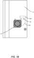
FIG. 1B illustrates an exemplary view of the cooling system ofFIG. 1A , wherein a grill cover is attached over the opening, and the outer body of the TRU in accordance with one or more embodiments of the disclosure. -
FIG. 1C illustrates an exemplary view depicting the outer body ofFIG. 1B having the grill cover attached over the opening provided on the outer body of the TRU in accordance with one or more embodiments of the disclosure -
FIGs. 2A to 2C illustrate exemplary views of the conduit used in the cooling system of the TRU in accordance with one or more embodiments of the disclosure. -
FIGs. 3A to 3E illustrate exemplary views of the grill cover of the cooling system of the TRU in accordance with one or more embodiments of the disclosure. - The following is a detailed description of embodiments of the disclosure depicted in the accompanying drawings. The embodiments are in such detail as to clearly communicate the disclosure. However, the amount of detail offered is not intended to limit the anticipated variations of embodiments; on the contrary, the intention is to cover all modifications, equivalents, and alternatives falling within the scope of the subject disclosure as defined by the appended claims.
- Various terms are used herein. To the extent a term used in a claim is not defined below, it should be given the broadest definition persons in the pertinent art have given that term as reflected in printed publications and issued patents at the time of filing.
- In the specification, reference may be made to the spatial relationships between various components and to the spatial orientation of various aspects of components as the devices are depicted in the attached drawings. However, as will be recognized by those skilled in the art after a complete reading of the subject disclosure, the components of this invention. described herein may be positioned in any desired orientation. Thus, the use of terms such as "above," "below," "upper," "lower," "first", "second" or other like terms to describe a spatial relationship between various components or to describe the spatial orientation of aspects of such components should be understood to describe a relative relationship between the components or a spatial orientation of aspects of such components, respectively, as the conduit, opening, VFD, grill cover, and corresponding components, described herein may be oriented in any desired direction.
- Referring to
FIG. 1A to 1C , an exemplary embodiment of thecooling system 100 for a variable frequency drive (VFD 108) and internal components of a transport refrigeration unit (TRU) or a vehicle is disclosed. The transport refrigeration unit includes a trailer refrigeration unit, a container refrigeration unit, a truck refrigeration unit, and the like. The TRU includes a cabinet being configured with a transportation cargo and theVFD 108 is associated with a compressor of a refrigeration system and/or one or fans associated with the TRU. Thesystem 100 includes aconduit 102 as shown inFIGs. 2A to 2C being disposed within achassis 104 of the cabinet of the TRU, such that theconduit 102 extends between aopening 106 provided at a first predefined position on theouter body 114 of the TRU and theVFD 108 being positioned internally within thebody 104 of the TRU. A first end 102-1 of theconduit 102 is adapted to be connected to theopening 106 and a second end 102-2 of theconduit 102 is disposed in proximity to theVFD 108. The second end 102-2 may be at an inlet side of the fan associated with the internal cooling system of theVFD 108. In other embodiments, an external fan can be provided on the door or first end of theconduit 102, thereby eliminating the requirement of an internal fan or internal cooling system for theVFD 108. The external fan at the door or duct serves the same purpose of cooling VFD with colder ambient air, by enabling the inflow of colder ambient air within theconduit 102 and directing the colder ambient air to the VFD to facilitate cooling of theVFD 108. Further, in one or more embodiments, a section 102-3 of theconduit 102 between the first end 102-1 and the second end 102-1, or thecomplete conduit 102 may be flexible, which allows easier positioning of theconduit 102 within thechassis 104 of the TRU. Thus, theopening 106 provided on theouter body 114 of the TRU facilitates the inflow of ambient air within theconduit 102 that carries the ambient air towards theVFD 108, thereby providing fresher lower ambient temperature air to theVFD 108 to maintain theVFD 108 at a safe operable temperature. In addition, theVFD 108 can be positioned at a second predefined position within the TRU such that theVFD 108 remains close to ambient and/or at a safe distance from an engine of the TRU such that the VFD remains thermally separated from the heat generated by the engine so as to minimize the transfer of heat from the engine to the VFD, thereby enabling quick and efficient cooling of theVFD 108. - In some embodiments, the
VFD 108 is positioned within the chassis on one side of the cabinet of the TRU, however, at a safe distance from the engine such that the VFD remains thermally separated from the engine to minimize the transfer of heat from the engine to the VFD. Further, theopening 106 is provided at theouter body 114 of the cabinet on the side where theVFD 108 is disposed. In other embodiments, theopening 106 is provided at the outer surface of thedoor 114 of the cabinet, and theVFD 108 is positioned withinchassis 104 of the cabinet on the door side of the TRU such that theVFD 108 remains thermally separated from the heat generated by the engine. In another embodiment, theopening 106 is provided at theouter body 114 in front of the cabinet, and theVFD 108 is positioned within the cabinet, however, theVFD 108 must be disposed away or at a safe distance from the engine of the TRU to reduce the effect of heat generated by the engine on the TRU. In addition, theconduit 102 may also extend between an air grill (not shown) or an inlet associated with a condenser of the TRU and theVFD 108 may be positioned within the cabinet of the TRU. This allows theconduit 102 orsystem 100 to directly receive ambient air from the air grill of the condenser and/or from the condenser. Thus, the cooling system orconduit 102 allows either the flow of ambient air from outside or cool air from the condenser inlet towards theVFD 108 to maintain theVFD 108 at a desired temperature. Similarly, theVFD 108 can also be positioned at other positions within the TRU, however, at a safe distance from the engine of the TRU, to minimize any effect from the heat of the engine on theVFD 108. In one or more embodiments, thesystem 100 includes aclamp 110, preferably having a U-shaped profile as shown inFIGs 1A and1B , being positioned at the interior side of theopening 106 to hold the first end 102-1 of theconduit 102 at theopening 106. However, the clamp of other designs or profiles may also be implemented in thecooling system 100. Theclamp 110 facilitates easier opening of the door as required to allow serviceability or maintenance of theVFD 108 orconduit 102. In addition,clamp 110 also allows easier fitting or alignment of thegrill cover 112 on the duct orconduit 102. Further, the rest of portions 102-2, 102-3 of theconduit 102 can extend within thechassis 104 of the TRU through a duct (not shown) extending between theopening 106 and theVFD 108. - The
system 100 includes agrill cover 112 as illustrated inFIGs 3A to 3E , that is adapted to be removably coupled to theopening 106 and/or the first end 102-1 of theconduit 102. A first end 112-1 of thegrill cover 112 is adapted to be attached to theouter body 114 of the TRU and a second end 112-2 of thegrill cover 112 is adapted to be attached to the first end of theconduit 102. The first end 112-1 of thegrill cover 112 may have a profile corresponding to a profile of theopening 106 and the second end 112-2 of thegrill cover 112 may have a profile corresponding to a profile of the first end 102-1 of theconduit 102, which enables attachment of the second end 112-2 of thegrill cover 112 to the first end 102-1 of theconduit 102 upon attaching thegrill cover 112 on theouter body 114 or opening 106 of the TRU. - The first end 112-1 of the
grill cover 112 includes amesh 302 having a plurality of pores. The pores may have a predefined profile and a predefined pore size that enables themesh 302 to allow entry of the ambient air within theconduit 102 and restrict the entry of outside objects and/or living organisms within theconduit 102. For example, the pores of thegrill cover 112 can have a honeycomb profile, circular profile, or polygonal profile, but are not limited to the like. Further, the second end 112-2 of thegrill cover 112 includes acollar 304 of a predefined length protruding from the surface of themesh 302. Thecollar 304 can be a cylindrical protrusion of a predetermined diameter and length, such that thecollar 304 gets attached and locked with the first end 102-1 of theconduit 102 upon attaching thegrill cover 112 to theopening 106. In one or more embodiments (now shown), thegrill cover 112 may be a louvered vent cover that facilitates air flow through a fixture that incorporates slanted pieces, which also the entry of outside objects, water, and/or living organisms within theconduit 102. Similarly, a grill cover having slant edges or other vent styles may also be configured with the opening and first end of theconduit 102. - An interior side of the first end 112-1 of the
grill cover 112 includes one or more engaging elements 306 (collectively referred to as engagingelements 306, herein) that are adapted to engage and lock with grooves (not shown) provided around theopening 106 on theouter body 114 of the TRU, thereby allowing easier attachment on and/or removal of thegrill cover 112 from theouter body 114 of the TRU. In one embodiment, thegrill cover 112 can be adapted to be snap-fitted to theouter body 114 of the TRU. In another embodiment, thegrill cover 112 can be an integral part of theouter body 114 of the TRU. Thegrill cover 112 may preferably be made of the same material as theouter body 114 of the TRU to enhance the aesthetics of the TRU, however, thegrill cover 112 may also be made of a different material. In one or more embodiments, the door is removably coupled to the chassis of the cabinet, which facilitates easier removal of the door as required to allow serviceability or maintenance of theVFD 108. In addition, this also allows easier fitting of thegrill cover 112, theconduit 102, and theclamp 110 with the TRU. Further, theconduit 102 is made of a material selected from one or more of plastic, polymer, fiber, and steel, but not limited to the like. - In one or more embodiments, the
system 100 includes an air filter (not shown) disposed within theconduit 102 and/or attached to thegrill cover 112 to clean the ambient air entering theconduit 102, which decreases degradation of theVFD 108 or internal components of the TRU. In addition, as shown inFIG. 2A , a predefined length of theconduit 102 at the first end 102-1 is elevated by a predefined angle (B) from a longitudinal axis (A-A') of theopening 106 to restrict the entry of water towards the second end 102-2 of theconduit 102 and allow automated discharge of water from theconduit 102 through theopening 106 or first end of theconduit 102. Theconduit 102 may either extend upward or downward within the body of the cabinet. Further, a flap (not shown) can be movably configured at the first end of theconduit 102 or theopening 106, such that when the vehicle moves or when the external fan at the door or inlet ofconduit 102 is turned ON, the ambient air automatically may move the flap to an open position, thereby opening theopening 106 and allowing the colder ambient air to flow within theconduit 102 and cool theVFD 108. Further, when the vehicle is stationary or when the external fan is tuned OFF, the flap automatically moves back to the closed position and covers theopening 106. Thus, thesystem 100 restricts the entry of outside objects, water, and/or living organisms within theconduit 102, thereby preventing theVFD 108 and other internal components of the TRU from weathering and degradation. - While various embodiments of this invention have been elaborated for a conduit having a circular cross-section, and the grill cover and the opening having a specific shape, however, the conduits, grill cover, and opening can also be of other shapes, sizes, and profiles. In addition, while embodiments of this invention have been elaborated for a cooling system for the VFD of a transport refrigeration unit (TRU), however, the cooling system can also be configured with any vehicle where external or ambient cooling is required.
- Thus, this invention (system) overcomes the drawbacks, limitations, and shortcomings associated with existing technologies by providing an external and efficient cooling system for the VFD in a transport refrigeration unit or a vehicle to provide fresher lower ambient temperature air to the VFD to maintain the VFD at a safe operable temperature.
- While the invention has been described with reference to exemplary embodiments, it will be understood by those skilled in the art that various changes may be made and equivalents may be substituted for elements thereof without departing from the scope of the invention as defined by the appended claims. Modifications may be made to adopt a particular situation or material to the teachings of the invention without departing from the scope thereof. Therefore, it is intended that the invention not be limited to the particular embodiment disclosed, but that the invention includes all embodiments falling within the scope of the invention as defined by the appended claims.
- In interpreting the specification, all terms should be interpreted in the broadest possible manner consistent with the context. In particular, the terms "comprises" and "comprising" should be interpreted as referring to elements, components, or steps in a nonexclusive manner, indicating that the referenced elements, components, or steps may be present, or utilized, or combined with other elements, components, or steps that are not expressly referenced. Where the specification claims refer to at least one of something selected from the group consisting of A, B, C ....and N, the text should be interpreted as requiring only one element from the group, not A plus N, or B plus N, etc.
Claims (15)
- A cooling system (100) for a variable frequency drive (VFD) (108) of a vehicle, the cooling system comprising:a conduit (102) disposed within the vehicle and extending between an opening (106) provided at a first predefined position on an outer body (114) of the vehicle and the VFD (108) being positioned at a second predefined position within the vehicle,wherein,the opening (106) facilitates inflow of ambient air within the conduit (102); andthe conduit (102) directs the ambient air towards the VFD (108) to enable cooling of the VFD.
- The cooling system of claim 1, wherein the conduit (102) comprises a first end (102-1) connected to the opening (106) and a second end (102-2) disposed in proximity to the VFD (108), and wherein at least a section (102-3) of the conduit between the first end and the second end is flexible.
- The cooling system of claim 1 or 2, wherein a predefined length of the conduit (102) at the first end (102-1) is elevated by a predefined angle (B) from a longitudinal axis (A) of the opening (106) to restrict entry of water towards the second end (102-2) of the conduit and allow automated discharge of water from the conduit through the opening.
- The cooling system of claim 2 or 3, wherein the first end (102-1) of the conduit (102) and/or a grill cover (112) are secured at the opening (106) by a clamp (110) provided at an interior side of the opening.
- The cooling system of claim 2, 3 or 4, wherein the cooling system comprises a grill cover (112) adapted to be removably coupled to the opening (106) and/or the first end (102-1) of the conduit (102), wherein a first end (112-1) of the grill cover is adapted to be attached to the outer body (114) of the vehicle and a second end (112-2) of the grill cover is adapted to be attached to the first end (102-1) of the conduit.
- The cooling system of claim 5, wherein the first end (112-1) of the grill cover (112) comprises a mesh (302) having a plurality of pores, wherein the pores have a predefined profile and a predefined pore size that enables the mesh to allow entry of the ambient air within the conduit (102) and restrict entry of outside objects and/or living organisms within the conduit.
- The cooling system of claim 5 or 6, wherein the second end (112-2) of the grill cover (112) comprises a collar (304) of a predefined length protruding from a surface of the mesh (302), wherein the collar is adapted to be attached and locked with the first end (102-1) of the conduit (102) upon attaching the grill cover on the opening (106).
- The cooling system of claim 5, 6 or 7, wherein the first end or the mesh of the grill cover (112) has a profile corresponding to a profile of the opening (106) and the collar (304) of the grill cover has a profile corresponding to a profile of the first end (102-1) of the conduit (102).
- The cooling system of any of claims 5 to 8, wherein the grill cover (112) is adapted to be snap-fitted to the outer body (114) of the vehicle; and/or wherein the first end (112-1) of the grill cover (112) comprises one or more engaging elements (306) adapted to engage and lock with the outer body (114) of the vehicle.
- The cooling system of claim 5, wherein the grill cover (112) is an integral part of the outer body (114) of the vehicle; and/or wherein the grill cover (112) is made of a material used for the outer body of the vehicle.
- The cooling system of any of claims 5 to 10, wherein the cooling system comprises an air filter disposed within the conduit (102) and/or in the VFD (108) and/or attached to the grill cover (112) to clean the ambient air entering the conduit.
- The cooling system of any preceding claim, wherein the conduit (102) is made of a material selected from one or more of plastic, polymer, rubber, fiber, and steel.
- The cooling system of any preceding claim, wherein the cooling system comprises a flap movably configured at the first end (102-1) of the conduit (102) or the opening (106), the flap is adapted to move between a close position and an open position, and
wherein,when the vehicle moves and/or an external fan associated with the VFD (108) turns ON, the airflow automatically moves the flap to the open position, thereby opening the opening and allowing the ambient air to flow within the conduit, andwhen the vehicle is stationary or when VFD fan is OFF, the flap automatically moves to the closed position and covers the opening. - The cooling system of any preceding claim, wherein the vehicle comprises a transport refrigeration unit (TRU) coupled to a transportation cargo, and wherein the VFD is operatively coupled to a compressor of a refrigeration system and/or one or more fans associated with the TRU.
- The cooling system of claim 14, wherein:the VFD (108) is positioned within a chassis (104) on one side of a cabinet of the TRU such that the VFD remains thermally separated from an engine of the TRU, and wherein the opening (106) is provided at the outer body (114) of the cabinet on the VFD side; orthe opening (106) is provided at an outer surface of a door of the cabinet and the VFD (108) is positioned within a chassis (104) of the cabinet on the door side such that the VFD remains thermally separated from an engine of the TRU; orthe opening (106) is provided at the outer body (114) at a front of the cabinet and the VFD (108) is positioned within the cabinet such that the VFD remains thermally separated from an engine of the TRU; orthe conduit (102) extends between an inlet or an air grill associated with a condenser of the TRU and the VFD (108) is positioned at the second predefined position within the cabinet, wherein the conduit is configured to direct the flow of air from inlet or outlet of the condenser to the VFD for cooling the VFD.
Applications Claiming Priority (1)
| Application Number | Priority Date | Filing Date | Title |
|---|---|---|---|
| US202263375940P | 2022-09-16 | 2022-09-16 |
Publications (2)
| Publication Number | Publication Date |
|---|---|
| EP4342706A1 true EP4342706A1 (en) | 2024-03-27 |
| EP4342706B1 EP4342706B1 (en) | 2026-02-25 |
Family
ID=88093557
Family Applications (1)
| Application Number | Title | Priority Date | Filing Date |
|---|---|---|---|
| EP23197804.0A Active EP4342706B1 (en) | 2022-09-16 | 2023-09-15 | Cooling system for a variable frequency drive in a transport refrigeration unit |
Country Status (3)
| Country | Link |
|---|---|
| US (1) | US20240093930A1 (en) |
| EP (1) | EP4342706B1 (en) |
| CN (1) | CN117719304A (en) |
Citations (8)
| Publication number | Priority date | Publication date | Assignee | Title |
|---|---|---|---|---|
| GB2343161A (en) * | 1998-10-28 | 2000-05-03 | Rover Group | Cooling of electrical equipment |
| US6902473B1 (en) * | 2004-01-06 | 2005-06-07 | Kenneth D. Goobeck | Vehicle ventilation conduit system |
| US20120031132A1 (en) * | 2009-05-25 | 2012-02-09 | Makoto Ikemiya | Trailer refrigerating apparatus |
| CN105658455A (en) * | 2013-10-23 | 2016-06-08 | 魏德塑料有限责任公司 | Motor vehicle with an additional cooling system |
| EP2168792B1 (en) * | 2008-09-25 | 2017-09-06 | KNORR-BREMSE Systeme für Nutzfahrzeuge GmbH | System and method for cooling an electronic control unit |
| US20180257458A1 (en) * | 2017-03-10 | 2018-09-13 | Mobile Climate Control, Corp. | Method and apparatus for cooling an air conditioning system controller |
| EP3415844A1 (en) * | 2016-06-20 | 2018-12-19 | Mitsubishi Heavy Industries Thermal Systems, Ltd. | Refrigerating unit for transportation |
| US20200333058A1 (en) * | 2018-01-18 | 2020-10-22 | Denso Corporation | Refrigeration device |
Family Cites Families (13)
| Publication number | Priority date | Publication date | Assignee | Title |
|---|---|---|---|---|
| US9426903B1 (en) * | 2008-06-27 | 2016-08-23 | Amazon Technologies, Inc. | Cooling air stack for computer equipment |
| EP3022497B1 (en) * | 2013-07-15 | 2023-09-20 | Carrier Corporation | Flame arrestors for use with a hvac/r system |
| MX2018011280A (en) * | 2016-03-17 | 2019-07-04 | Fresh Chill Solutions Inc | Methods, apparatuses, and systems for cooling. |
| CL2016001817A1 (en) * | 2016-07-18 | 2017-07-14 | Liventus Chile S A | Hatch device comprising a main support body (3), a flow conduction piece (24) and optionally a plug (30), which allows a minimal modification in the structure of the service hatch cover () 2) |
| US10212861B2 (en) * | 2017-02-24 | 2019-02-19 | Halliburton Energy Services, Inc. | Variable frequency drive cabinet ventilation system, apparatus and method |
| US10359203B2 (en) * | 2017-06-26 | 2019-07-23 | Therma-Stor LLC | Portable desiccant dehumidifier |
| US11191191B2 (en) * | 2017-12-11 | 2021-11-30 | Schlumberger Technology Corporation | Air cooled variable-frequency drive |
| US20220354020A1 (en) * | 2019-09-06 | 2022-11-03 | Carlisle Interconnect Technologies, Inc. | Mounting System For Mounting An Element To An Aircraft Surface |
| US11623499B2 (en) * | 2019-11-08 | 2023-04-11 | Thermo King Llc | Electrical power supply management for climate-controlled system associated with automotive application |
| CN111130001B (en) * | 2020-01-18 | 2021-08-31 | 深圳市创奇电气有限公司 | Indoor AC metal armoured movable switch equipment |
| US12085317B2 (en) * | 2020-04-20 | 2024-09-10 | Tyco Fire & Security Gmbh | System and method of cooling of heat generating units in an HVAC unit |
| CN112993793A (en) * | 2021-05-10 | 2021-06-18 | 山东汉鑫尊新材料有限公司 | Outdoor prevention of seepage switch board |
| US20240010049A1 (en) * | 2022-07-05 | 2024-01-11 | Carrier Corporation | Multi-compartment transport refrigeration system |
-
2023
- 2023-09-13 US US18/466,511 patent/US20240093930A1/en active Pending
- 2023-09-14 CN CN202311188775.1A patent/CN117719304A/en active Pending
- 2023-09-15 EP EP23197804.0A patent/EP4342706B1/en active Active
Patent Citations (8)
| Publication number | Priority date | Publication date | Assignee | Title |
|---|---|---|---|---|
| GB2343161A (en) * | 1998-10-28 | 2000-05-03 | Rover Group | Cooling of electrical equipment |
| US6902473B1 (en) * | 2004-01-06 | 2005-06-07 | Kenneth D. Goobeck | Vehicle ventilation conduit system |
| EP2168792B1 (en) * | 2008-09-25 | 2017-09-06 | KNORR-BREMSE Systeme für Nutzfahrzeuge GmbH | System and method for cooling an electronic control unit |
| US20120031132A1 (en) * | 2009-05-25 | 2012-02-09 | Makoto Ikemiya | Trailer refrigerating apparatus |
| CN105658455A (en) * | 2013-10-23 | 2016-06-08 | 魏德塑料有限责任公司 | Motor vehicle with an additional cooling system |
| EP3415844A1 (en) * | 2016-06-20 | 2018-12-19 | Mitsubishi Heavy Industries Thermal Systems, Ltd. | Refrigerating unit for transportation |
| US20180257458A1 (en) * | 2017-03-10 | 2018-09-13 | Mobile Climate Control, Corp. | Method and apparatus for cooling an air conditioning system controller |
| US20200333058A1 (en) * | 2018-01-18 | 2020-10-22 | Denso Corporation | Refrigeration device |
Also Published As
| Publication number | Publication date |
|---|---|
| CN117719304A (en) | 2024-03-19 |
| EP4342706B1 (en) | 2026-02-25 |
| US20240093930A1 (en) | 2024-03-21 |
Similar Documents
| Publication | Publication Date | Title |
|---|---|---|
| US10029558B2 (en) | Grille shutter assembly | |
| US6101829A (en) | Air conditioning apparatus | |
| US8182217B2 (en) | Mechanical fan sub-shroud attachment feature, molded plastic snap feature | |
| EP1961599B1 (en) | Truck electrified engine-off air conditioning system | |
| EP2212135B1 (en) | A vehicle-cabin air-conditioning system and a module containing the system | |
| US8622162B2 (en) | Engine compartment cooling system | |
| US20080188175A1 (en) | Air circulator with releasable air grille | |
| EP1975534A3 (en) | Internal heat exchanger for an air-conditioning installation | |
| US10675942B2 (en) | Condenser unit of a roof-mounted air conditioning system | |
| US20140220875A1 (en) | Floor pan for connecting a roof-mounted cooling device to the roof of a switchgear cabinet | |
| EP4342706B1 (en) | Cooling system for a variable frequency drive in a transport refrigeration unit | |
| EP3764034A1 (en) | Refrigerator with means for noise reduction | |
| US20140202660A1 (en) | Cooling system and a method for its use | |
| JP2003146070A (en) | Moving refrigeration unit | |
| CN101952130B (en) | Front cover for transport refrigeration unit | |
| EP2861460B1 (en) | Transportation refrigeration bulkhead | |
| US9109828B2 (en) | Convertible and compact refrigeration system | |
| US20160061237A1 (en) | Apparatus and method to enhance heating performance of a vehicle ventilation system | |
| US20160052372A1 (en) | Retrofit debris shield for vehicle air conditioning systems | |
| JP7481286B2 (en) | Air conditioning equipment | |
| EP3792181B1 (en) | Managing condensate drainage within chilled air ductwork background | |
| DE102014211112A1 (en) | Condenser assembly for a refrigeration unit | |
| EP4600499A2 (en) | Refrigeration system stator mount | |
| EP4733694A2 (en) | Transport refrigeration unit | |
| US20240336115A1 (en) | Air distributor for transport refrigeration unit of a vehicle |
Legal Events
| Date | Code | Title | Description |
|---|---|---|---|
| PUAI | Public reference made under article 153(3) epc to a published international application that has entered the european phase |
Free format text: ORIGINAL CODE: 0009012 |
|
| STAA | Information on the status of an ep patent application or granted ep patent |
Free format text: STATUS: THE APPLICATION HAS BEEN PUBLISHED |
|
| AK | Designated contracting states |
Kind code of ref document: A1 Designated state(s): AL AT BE BG CH CY CZ DE DK EE ES FI FR GB GR HR HU IE IS IT LI LT LU LV MC ME MK MT NL NO PL PT RO RS SE SI SK SM TR |
|
| STAA | Information on the status of an ep patent application or granted ep patent |
Free format text: STATUS: REQUEST FOR EXAMINATION WAS MADE |
|
| 17P | Request for examination filed |
Effective date: 20240927 |
|
| RBV | Designated contracting states (corrected) |
Designated state(s): AL AT BE BG CH CY CZ DE DK EE ES FI FR GB GR HR HU IE IS IT LI LT LU LV MC ME MK MT NL NO PL PT RO RS SE SI SK SM TR |
|
| GRAP | Despatch of communication of intention to grant a patent |
Free format text: ORIGINAL CODE: EPIDOSNIGR1 |
|
| STAA | Information on the status of an ep patent application or granted ep patent |
Free format text: STATUS: GRANT OF PATENT IS INTENDED |
|
| INTG | Intention to grant announced |
Effective date: 20250919 |
|
| GRAS | Grant fee paid |
Free format text: ORIGINAL CODE: EPIDOSNIGR3 |
|
| GRAA | (expected) grant |
Free format text: ORIGINAL CODE: 0009210 |
|
| STAA | Information on the status of an ep patent application or granted ep patent |
Free format text: STATUS: THE PATENT HAS BEEN GRANTED |
|
| AK | Designated contracting states |
Kind code of ref document: B1 Designated state(s): AL AT BE BG CH CY CZ DE DK EE ES FI FR GB GR HR HU IE IS IT LI LT LU LV MC ME MK MT NL NO PL PT RO RS SE SI SK SM TR |
|
| REG | Reference to a national code |
Ref country code: CH Ref legal event code: F10 Free format text: ST27 STATUS EVENT CODE: U-0-0-F10-F00 (AS PROVIDED BY THE NATIONAL OFFICE) Effective date: 20260225 Ref country code: GB Ref legal event code: FG4D |
|
| REG | Reference to a national code |
Ref country code: DE Ref legal event code: R096 Ref document number: 602023012526 Country of ref document: DE |
|
| REG | Reference to a national code |
Ref country code: IE Ref legal event code: FG4D Ref country code: NL Ref legal event code: FP |