EP4342631A1 - Process for shaping an ophthalmic product - Google Patents
Process for shaping an ophthalmic product Download PDFInfo
- Publication number
- EP4342631A1 EP4342631A1 EP22306407.2A EP22306407A EP4342631A1 EP 4342631 A1 EP4342631 A1 EP 4342631A1 EP 22306407 A EP22306407 A EP 22306407A EP 4342631 A1 EP4342631 A1 EP 4342631A1
- Authority
- EP
- European Patent Office
- Prior art keywords
- machining
- ophthalmic product
- shaping according
- lens
- ophthalmic
- Prior art date
- Legal status (The legal status is an assumption and is not a legal conclusion. Google has not performed a legal analysis and makes no representation as to the accuracy of the status listed.)
- Pending
Links
Images

Classifications
-
- B—PERFORMING OPERATIONS; TRANSPORTING
- B24—GRINDING; POLISHING
- B24B—MACHINES, DEVICES, OR PROCESSES FOR GRINDING OR POLISHING; DRESSING OR CONDITIONING OF ABRADING SURFACES; FEEDING OF GRINDING, POLISHING, OR LAPPING AGENTS
- B24B51/00—Arrangements for automatic control of a series of individual steps in grinding a workpiece
-
- B—PERFORMING OPERATIONS; TRANSPORTING
- B24—GRINDING; POLISHING
- B24B—MACHINES, DEVICES, OR PROCESSES FOR GRINDING OR POLISHING; DRESSING OR CONDITIONING OF ABRADING SURFACES; FEEDING OF GRINDING, POLISHING, OR LAPPING AGENTS
- B24B49/00—Measuring or gauging equipment for controlling the feed movement of the grinding tool or work; Arrangements of indicating or measuring equipment, e.g. for indicating the start of the grinding operation
- B24B49/006—Measuring or gauging equipment for controlling the feed movement of the grinding tool or work; Arrangements of indicating or measuring equipment, e.g. for indicating the start of the grinding operation taking regard of the speed
-
- B—PERFORMING OPERATIONS; TRANSPORTING
- B24—GRINDING; POLISHING
- B24B—MACHINES, DEVICES, OR PROCESSES FOR GRINDING OR POLISHING; DRESSING OR CONDITIONING OF ABRADING SURFACES; FEEDING OF GRINDING, POLISHING, OR LAPPING AGENTS
- B24B49/00—Measuring or gauging equipment for controlling the feed movement of the grinding tool or work; Arrangements of indicating or measuring equipment, e.g. for indicating the start of the grinding operation
- B24B49/02—Measuring or gauging equipment for controlling the feed movement of the grinding tool or work; Arrangements of indicating or measuring equipment, e.g. for indicating the start of the grinding operation according to the instantaneous size and required size of the workpiece acted upon, the measuring or gauging being continuous or intermittent
-
- B—PERFORMING OPERATIONS; TRANSPORTING
- B24—GRINDING; POLISHING
- B24B—MACHINES, DEVICES, OR PROCESSES FOR GRINDING OR POLISHING; DRESSING OR CONDITIONING OF ABRADING SURFACES; FEEDING OF GRINDING, POLISHING, OR LAPPING AGENTS
- B24B49/00—Measuring or gauging equipment for controlling the feed movement of the grinding tool or work; Arrangements of indicating or measuring equipment, e.g. for indicating the start of the grinding operation
- B24B49/16—Measuring or gauging equipment for controlling the feed movement of the grinding tool or work; Arrangements of indicating or measuring equipment, e.g. for indicating the start of the grinding operation taking regard of the load
-
- B—PERFORMING OPERATIONS; TRANSPORTING
- B24—GRINDING; POLISHING
- B24B—MACHINES, DEVICES, OR PROCESSES FOR GRINDING OR POLISHING; DRESSING OR CONDITIONING OF ABRADING SURFACES; FEEDING OF GRINDING, POLISHING, OR LAPPING AGENTS
- B24B9/00—Machines or devices designed for grinding edges or bevels on work or for removing burrs; Accessories therefor
- B24B9/02—Machines or devices designed for grinding edges or bevels on work or for removing burrs; Accessories therefor characterised by a special design with respect to properties of materials specific to articles to be ground
- B24B9/06—Machines or devices designed for grinding edges or bevels on work or for removing burrs; Accessories therefor characterised by a special design with respect to properties of materials specific to articles to be ground of non-metallic inorganic material, e.g. stone, ceramics, porcelain
- B24B9/08—Machines or devices designed for grinding edges or bevels on work or for removing burrs; Accessories therefor characterised by a special design with respect to properties of materials specific to articles to be ground of non-metallic inorganic material, e.g. stone, ceramics, porcelain of glass
- B24B9/14—Machines or devices designed for grinding edges or bevels on work or for removing burrs; Accessories therefor characterised by a special design with respect to properties of materials specific to articles to be ground of non-metallic inorganic material, e.g. stone, ceramics, porcelain of glass of optical work, e.g. lenses, prisms
Definitions
- the present invention generally relates to the field of eyeglasses.
- This invention applies to machining devices comprising:
- the invention more particularly relates to a process for shaping an ophthalmic lens, comprising:
- the technical part of the work of an optician which consists in mounting a pair of ophthalmic lenses in a spectacle frame selected by a customer, may be split into four main operations:
- the edging operation is more particularly of interest.
- This operation is generally carried out by an edging machine, as a function of the material of the lens to be edged.
- the machining method aims at maintaining constant the machining speed, that is to say the speed of the contact point between the lens and the tool.
- the control parameters are consequently calculated before machining the lens, considering the material of the lens to be edged.
- the machining depth is calculated according to the average power consumed by the motor at the previous turn, in order to reduce the time needed to edge the lens.
- the present invention provides a solution enabling to use the edging machine to its maximum capacity in order to optimize productivity.
- the invention is directed to a process for shaping an ophthalmic product as defined in the introduction wherein, during the step of roughing out, the value of said force is measured by the force sensor, and the machining speed is continuously adjusted so as to maintain the measured value equal to a target value.
- the tool is driven so as to machine the ophthalmic product at the maximum possible speed.
- the target value is maintained at a level that is high in order to shorten the machining time, and that is such that the motor consumption does not exceed a maximum value that would harm the quality of the product.
- Figure 1 shows a device 200 for machining an ophthalmic lens 20, comprising:
- This machining device 200 could take the form of any machine for cutting or removing material, able to modify the outline of the ophthalmic lens 20 in order to adapt it to that of the corresponding eyewire of a spectacle frame selected by an individual.
- the machining device 200 consists, as is known per se, of an automatic grinder 200, widely referred to as a digital grinder.
- this grinder comprises:
- the pivoting mobility of the rocker 201 about the reference axis is called retraction mobility ESC. It allows the ophthalmic lens 20 to be brought closer to the abrasive wheel 210 until the former makes contact with the latter.
- This rocker 201 is equipped with two shafts 202, 203 for clamping the ophthalmic lens 20 to be machined and for driving it to rotate, which shafts 202, 203 correspond to the aforementioned "clamping means".
- Each of the shafts 202, 203 possesses a free end that faces the other and that is equipped with a head for clamping the ophthalmic lens 20.
- a first 202 of the two shafts is fixed in translation along the clamping axis A7.
- the second 203 of the two shafts is mobile in translation along the blocking axis A7 in order to allow the ophthalmic lens 20 to be compressively clamped axially between the two clamping heads.
- the grinder 200 schematically shown in figure 1 comprises only one cylinder abrasive wheel 210.
- each abrasive wheel being used for a specific shaping operation of the ophthalmic lens 20 to be machined.
- a roughing-out cylinder abrasive wheel is used for the roughing-out of the lens.
- This roughing-out cylinder abrasive wheel is cylindrical, it has a diameter greater than 10 centimetres, and it comprises diamonds whose grain size is between 100 and 500 micrometers and is here equal to 300 micrometers.
- a shaping abrasive wheel (or “beveling abrasive wheel”) can be used, this abrasive wheel containing a beveling groove of dihedral cross-section.
- a cylinder abrasive wheel and a shaping abrasive wheel are used, the grain sizes of these polishing abrasive wheels being particularly small.
- the set of abrasive wheels is born by a slide (not shown) so as to move in translation along the abrasive-wheel axis A6.
- the translational movement of the slide bearing the abrasive wheels is called the "transfer" TRA.
- the grinder 200 furthermore comprises a link rod 230 one end of which is hinged relative to the mounting in order to pivot about the reference axis A5, and the other end of which is hinged relative to a nut 231 in order to pivot about an axis A8 parallel to the reference axis A5.
- the nut 231 is itself mounted to move in translation along a restitution axis A9 perpendicular to the reference axis A5.
- the nut 231 is a tapped nut in screwed engagement with a threaded shank 232 that, aligned with the restitution axis A9, is driven to rotate by a motor 233.
- the link rod 230 moreover comprises a force sensor 234, here consisting of a unidirectional strain gauge, that interacts with a stop 204 fixed to the rocker 201.
- the ophthalmic lens 20 to be machined When, duly clamped between the two shafts 202, 203, the ophthalmic lens 20 to be machined is brought into contact with one of the abrasive wheels 210, it is the object of an effective removal of material until the stop 204 of the rocker 201 buts against the link rod 230 with a force that, acting on the strain gauge 234, is duly detected and measured by the latter.
- the strain gauge 234 is placed so as to measure a machining force of substantially vertical direction, corresponding to the radial component of the force exerted by the ophthalmic lens 20 on the abrasive wheel 210 or finishing tool 222, 223 used.
- the retraction movement is in particular controlled depending on the machining force measured by the strain gauge 234, so as to maintain it equal to a target value.
- the non-essential finishing module 220 has a pivoting mobility about the abrasive-wheel axis A6, which mobility is denoted PIV. This mobility allows it to be brought closer to or moved further away from the ophthalmic lens 20.
- finishing tools 222, 223 with which the finishing module 220 is equipped here especially comprise a grooving disk 222 adapted to produce a groove along the edge face of the ophthalmic lens 20, and a milling cutter 223 adapted to chamfer the sharp edges of the ophthalmic lens 20.
- finishing tools 222, 223 are mounted to rotate about a given axis and are driven to rotate by a motor housed in a base 224 that is itself mounted to pivot on the finishing module 220 about an axis A10 orthogonal to the abrasive-wheel axis A6.
- This pivoting mobility of the base 224 about the axis A10 called the finishing mobility FIN, allows the tools 222, 223 to be best oriented relative to the lens.
- the controlling unit 251 is an electronic and/or computing unit and it in particular allows the following to be controlled:
- the grinder 200 comprises a human-machine interface 252 that here comprises a display screen 253, a keyboard 254 and a mouse 255, which are adapted to communicate with the controlling unit 251.
- This HMI interface 252 allows the user to enter numerical values, such as the material of the lens, on the display screen 253, so that the tools of the grinder 200 can be appropriately controlled.
- the controlling unit is implemented on a desktop computer connected to the grinder 200.
- the software portion of the grinder could be implemented directly on an electronic circuit of the grinder. It could also be implemented on a remote computer, communicating with the grinder via a private or public network, for example using an IP (Internet) communication protocol.
- IP Internet
- Figure 2 shows a projection of the initial outline 21 of the lens 20 to be machined.
- This final outline 22 corresponds to the bottom of a bezel of a rim of the spectacle frame selected by the individual that is suitable to receive the lens once machined.
- Figure 2 also shows a "boxing system" of this final outline 22.
- this boxing system comprises a box 23 that is a rectangle drawn around the projection of the final outline 22, which has two horizontal sides.
- the centre O of this box 23 is called boxing center.
- the lens is to be blocked between the two shafts 202, 203 such that the blocking axis A7 passes through this boxing center.
- the controlling unit 251 acquires the geometry of the final outline 22.
- this final outline 22 takes the form of a set of triplets (r i , ⁇ i , z i ) corresponding to the cylindrical coordinates of a plurality of points P i characterizing the shape of this final outline 22.
- These coordinates can be acquired from a database to which an optician has access, or by using an imaging device comprising image-capturing means and image-processing means suitable to process a photo of a sample lens delivered with the spectacle frame, or by feeling the bottom of the bezel of the rim of the frame selected by the individual.
- the lens is then subjected to a centering operation followed by a blocking operation.
- the positions of markers marked or etched on the lens are determined, and the position required for the final outline 22 is deduced therefrom (so that once the lens has been shaped following this outline and fitted into the selected frame, its optical centre is correctly located relative to the corresponding eye of the spectacle wearer).
- a gripping accessory is adhesively bonded to the lens in a position centered on the boxing centre, then, by virtue of this gripping accessory, the lens is clamped between the shafts 202, 203 of the edger 200 such that the boxing centre is located centered on the clamping axis A7.
- the shaping is then carried out in two operations, namely a roughing-out operation and a finishing operation.
- the roughing-out cylinder abrasive wheel 210 is used to coarsely decrease the radii of the lens 20 to the shape of the final outline 22. More precisely, the shafts 202, 203 and the rocker 201 are here controlled relative to each other so as to decrease, for each angular position ⁇ i of the lens about the clamping axis A7, the radius of the lens to a length equal to the radius r i of the final outline 20.
- the shaping abrasive wheel and/or any other finishing tool is used to form, on the edge face of the lens, a "bevel" or a groove or any suitable form, and to polish the obtained edge.
- the invention is more particularly directed to the step of roughing-out.
- the abrasive wheel 210 follows, relative to the lens 20, a first path Pa1 that is radiale relative to the axis A7 until its peripheral edge reaches the final outline 22. Then, it follows a second path Pa2 along the final outline 22 (see Fig.2 ).
- the lens 20 is machined in a single pass around the axis A7.
- the roughing-out step is performed so as to reduce the time required to machine the edge of the lens 20.
- machining speed MSp also called “machining rate”
- This machining speed could be defined as being the rotation speed of the shafts 202, 203.
- the machining speed is defined as the speed of the point of contact between the lens 20 and the abrasive wheel 210.
- this machining speed MSp depends on the rotation speed of the shafts 202, 203 and on the radius of the contact point relative to axis A7.
- the grinder 200 is designed so that the machining speed MSp can reach a known "maximum machining speed" or a known shaft rotation speed.
- the grinding machine 200 is designed such that it can reach a known “maximum shaft rotation speed” or so that the machining speed MSp can reach a known “maximum machining speed”.
- the process for roughing-out the lens 20 is performed in loops so that the machining of the lens edge progresses at each loop point by point along the final outline 22.
- sampling interval ⁇ t the time between two successive loops.
- the idea of the invention is to discretise the final outline 22 into several main points and to search in real time for the next point to be reached at the end of each instant sampling interval ⁇ t.
- the first main point P 0 can be selected randomly.
- the number N of main points P i (with i lying from 0 to N-1) is determined as a function of said maximum machining speed and/or of said maximum shaft rotation speed.
- the maximum shaft rotation speed is considered.
- the latter is regarded as being equal to 10 rpm when the sampling interval ⁇ t is settled to 1 ms.
- the final outline 22 is initially characterized by 6000 main points P i the coordinates (r i , ⁇ i , z i ) of which are defined.
- intermediate points P 0j are added in real time during the roughing-out step and they are defined only by one of their coordinates: their orientation ⁇ j .
- the use of intermediate points P 0j rather than a greater number N of main points P i enables not to have to determine a great number of triplets (r i , ⁇ i , z i ).
- sampling The method used to add these intermediate points P 0j is named sampling. In practice, it consists in adding, at each loop and only if it is necessary, a predefined number n of intermediate points P 0j between the two next main points P i .
- these intermediate points P 0j are added between the main points P 0 and P 1 .
- the predefined number n of added intermediate points P 0j is at least equal to 10, and is here equal to 100.
- next point P t+1 to be reached at the next sampling instant t+1 is selected between these intermediate points P 0j and the second main point P 1 , so as to maintain the measured value F meas equal to a target value F targ (see the second drawing of Figure 3 ).
- the first parameter is the target value F targ of the measured force
- the second parameter is the machining speed Msp.
- the method for adjusting the target value F targ according to the intrinsic characteristics of the material of the lens (kind of material, amount of material to machine%) and to the operating conditions of the machine (electrical voltage, state of maintenance%) is shown in the left part of Figure 4 . It comprises several steps.
- these steps are performed in loops, but these loops can be desynchronized from the above-mentioned loops.
- the sampling interval of these desynchronized loops can be distinct from said sampling interval ⁇ t and can vary from one loop to another.
- the first step S0 shown in Figure 4 represents the beginning of the roughing-out step.
- the second step S2 consists in determining an initial target value F targ .
- this initial target value depends only from the operating conditions of the grinder 200, and more specifically from its nominal power.
- step S4 the determined target value F targ is compared with a predetermined threshold F up .
- This predetermined threshold F up depends on the used grinder 200. It is for instance equal to 2500g. It corresponds to a minimum value of the force below which it is considered that no problem can arise.
- step S12 (described hereinafter) is implemented.
- step S6 the instant electrical power P el consumed by the grinder 200 is acquired and compared with a power threshold P max .
- This power threshold P max depends on the used grinder. It is for instance equal to 900W. It corresponds to a power equal or next from the maximum power the grinder can consume.
- step S12 is implemented.
- the target value F targ is reduced of a predetermined amount. This amount is for instance equal to 500g.
- step S10 a temporisation is triggered, then step S12 is implemented.
- This temporisation is for instance of 0.8s.
- Step S12 consists in determining whether the roughing-out step is finished or not.
- step S14 If it is finished, the process ends (step S14). Else, the process is restarted at step S4.
- the target value F targ is adjusted as a function of the grinder possibilities.
- a new machining speed Msp is determined at each loop defined by the sampling interval ⁇ t.
- the process for adjusting the machining speed MSp according to the target value F targ and to the measured value F meas is implemented in parallel of the determination of said target value.
- This process is based on a proportional derivative controller and comprises the following steps.
- the processing unit 251 determines a first difference between the measured value F meas and the target value F targ , named force error ⁇ F.
- the processing unit 251 calculates the machining speed MSp according to the force error ⁇ F and the derivative ⁇ F.
- the processing unit is able to determine the next point P t+1 to be reached at the end of the sampling interval ⁇ t.
- the processing units determines its coordinates (r j , ⁇ j , z j ). Indeed, only the orientations ⁇ j of the intermediate points P 0j are known.
- the other coordinates can be determined by interpolation, on the basis of at least the orientation ⁇ j and the coordinates (r i , ⁇ i , z i ) and (r i+1 , ⁇ i+1 , z i+1 ) of the two main points located on either side of the next point P t+1 .
- the process can apply to the machining of other ophthalmic products, for instance to the machining of molds suitable for molding ophthalmic lenses.
Landscapes
- Engineering & Computer Science (AREA)
- Mechanical Engineering (AREA)
- Chemical & Material Sciences (AREA)
- Ceramic Engineering (AREA)
- Inorganic Chemistry (AREA)
- Grinding And Polishing Of Tertiary Curved Surfaces And Surfaces With Complex Shapes (AREA)
Abstract
- a step of clamping the ophthalmic product in said clamping means; and
- a step of roughing out the ophthalmic product by means of the machining tool so as to bring the initial outline of the ophthalmic product to a final outline of different shape,
wherein, during the step of roughing out:
- the value of said force is measured by the force sensor, and
- the machining speed is continuously adjusted so as to maintain the measured value equal to a target value.
Description
- The present invention generally relates to the field of eyeglasses.
- This invention applies to machining devices comprising:
- clamping means for clamping an ophthalmic product,
- a machining tool for machining the ophthalmic product, and
- a force sensor adapted to measure a force that is related to the force applied by the machining tool to the ophthalmic product.
- The invention more particularly relates to a process for shaping an ophthalmic lens, comprising:
- a step of clamping the ophthalmic product in said clamping means; and
- a step of roughing out the ophthalmic product by means of the machining tool so as to bring the initial outline of the ophthalmic product to a final outline of different shape.
- The technical part of the work of an optician, which consists in mounting a pair of ophthalmic lenses in a spectacle frame selected by a customer, may be split into four main operations:
- the acquisition of the shapes of the outlines of the rims of the spectacle frame selected by the customer,
- the centering of each ophthalmic lens, which consists in determining the frame of reference of the lens using centering markings provided thereon, then in suitably positioning the outline of the rim acquired beforehand in the frame of reference of the lens so that, once edged to this outline then mounted in its frame, the lens is correctly positioned with respect to the corresponding eye of the customer and fulfils as best as possible the optical function for which it was designed,
- the blocking of each lens, which consists in attaching a blocking accessory to the lens, so that the lens can be easily extracted from the centering station and then be engaged in the edging station without loss of frame of reference, then
- the edging of each lens, which consists in machining this lens to the outline centered beforehand.
- Here, the edging operation is more particularly of interest.
- This operation is generally carried out by an edging machine, as a function of the material of the lens to be edged.
- Various processes are known to perform this operation.
- In a known embodiment, the machining method aims at maintaining constant the machining speed, that is to say the speed of the contact point between the lens and the tool. The control parameters are consequently calculated before machining the lens, considering the material of the lens to be edged.
- In a second known embodiment, when the lens is to be machined in several passes, at each pass, the machining depth is calculated according to the average power consumed by the motor at the previous turn, in order to reduce the time needed to edge the lens.
- These two methods are based on the assumption that the machining operations are repeatable and that the performances of the tools are constant over time.
- But in practice, this assumption is wrong. Consequently, the edging machine is not used at the maximum of its possibilities.
- In this context, the present invention provides a solution enabling to use the edging machine to its maximum capacity in order to optimize productivity.
- More specifically, the invention is directed to a process for shaping an ophthalmic product as defined in the introduction wherein, during the step of roughing out, the value of said force is measured by the force sensor, and the machining speed is continuously adjusted so as to maintain the measured value equal to a target value.
- Consequently, at each instant, the tool is driven so as to machine the ophthalmic product at the maximum possible speed.
- In a preferred embodiment, the target value is maintained at a level that is high in order to shorten the machining time, and that is such that the motor consumption does not exceed a maximum value that would harm the quality of the product.
- Other preferred features of the invention are the following ones:
- during the step of roughing out, the machining tool follows a first path that is radiale relative to said clamping means until it reaches the final outline, and a second path along said final outline.
- the force sensor is adapted to measure a force component that is radiale relative to said clamping means.
- said target value is determined as a function of an electrical power consumed by the machining device.
- during said step of roughing out, a comparison operation is performed to compare the electrical power consumed by the machining device with a power threshold, and when the electrical power consumed by the machining device is greater than said power threshold, said target value is reduced of a predetermined amount.
- the comparison operation is performed only when said target value is greater than a predetermined threshold.
- said machining speed is determined by means of a proportional derivative controller.
- said machining speed is determined as a function of a first difference between said measured value and said target value, and a second difference between the measured value, measured at a current instant, and a measured value measured at a previous instant.
- the final outline being characterized by first points (also named main points), intermediate points are defined between said first points, and during the roughing out step, at each sampling instant, said machining device is programmed to:
- ¤ select a next point to be reached among the first points and the intermediate points as a function of the difference between said measured value and said target value, and to
- ¤ control said machining tool and said clamping means such that the machining tool reaches said next point in a predetermined time amount that is constant from a sampling instant to another.
- the number of first points is determined as a function of a maximum machining speed and/or of a maximum speed of the machining device.
- said ophthalmic product is an ophthalmic lens or a mold for molding an ophthalmic lens.
- the process comprises, after said step of roughing out, a finishing step that is performed on the part of the ophthalmic product machined by said machining tool, by means of a finishing tool that is distinct from said machining tool.
- during said step of roughing out, said ophthalmic product is machined by the machining tool in a single pass around said clamping means.
- The following description with reference to the accompanying drawings, given by way of non-limiting example makes it clear what the invention consists in and how it can be reduced to practice.
- In the accompanying drawings:
-
Figure 1 is a schematic view of a machining device adapted to implement a process according to the invention, -
Figure 2 illustrates an initial and a final outline of an ophthalmic lens before and after machining by means of the device ofFigure 1 , -
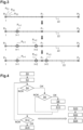
Figure 3 shows how some points of the final outline are defined according to the invention, and -
Figure 4 is a flowchart of the process according to the invention. -
Figure 1 shows adevice 200 for machining anophthalmic lens 20, comprising: - means 202, 203 for clamping the
ophthalmic lens 20; - at least one
tool ophthalmic lens 20; - a
force sensor 234 adapted to measure a force related to the force applied by themachining tool ophthalmic lens 20; and - a
unit 251 for controlling eachmachining tool - This
machining device 200 could take the form of any machine for cutting or removing material, able to modify the outline of theophthalmic lens 20 in order to adapt it to that of the corresponding eyewire of a spectacle frame selected by an individual. - In the example schematically illustrated in
figure 1 , themachining device 200 consists, as is known per se, of anautomatic grinder 200, widely referred to as a digital grinder. In this case, this grinder comprises: - a
rocker 201 that is mounted so as to freely pivot about a reference axis A5, in practice a horizontal axis, on a mounting (not shown), and that supports theophthalmic lens 20 to be machined; - at least one
abrasive wheel 210 that is mounted so as to pivot about an abrasive-wheel axis A6 parallel to the reference axis A5, and that is also duly driven to rotate by a motor (not shown); - a
finishing module 220 that is fitted so as to rotate about the abrasive-wheel axis A6, and that is equipped withtools ophthalmic lens 20. - The pivoting mobility of the
rocker 201 about the reference axis is called retraction mobility ESC. It allows theophthalmic lens 20 to be brought closer to theabrasive wheel 210 until the former makes contact with the latter. - This
rocker 201 is equipped with twoshafts ophthalmic lens 20 to be machined and for driving it to rotate, which shafts 202, 203 correspond to the aforementioned "clamping means". - These two
shafts shafts ophthalmic lens 20. - A first 202 of the two shafts is fixed in translation along the clamping axis A7. In contrast, the second 203 of the two shafts is mobile in translation along the blocking axis A7 in order to allow the
ophthalmic lens 20 to be compressively clamped axially between the two clamping heads. - The
grinder 200 schematically shown infigure 1 comprises only one cylinderabrasive wheel 210. - In practice, it rather comprises a set of abrasive wheels mounted coaxially on the abrasive-wheel axis A6, each abrasive wheel being used for a specific shaping operation of the
ophthalmic lens 20 to be machined. - For the roughing-out of the lens, a roughing-out cylinder abrasive wheel is used. This roughing-out cylinder abrasive wheel is cylindrical, it has a diameter greater than 10 centimetres, and it comprises diamonds whose grain size is between 100 and 500 micrometers and is here equal to 300 micrometers.
- For the beveling of the lens, which consists in machining a rib along the edge face of the lens, a shaping abrasive wheel (or "beveling abrasive wheel") can be used, this abrasive wheel containing a beveling groove of dihedral cross-section.
- For the polishing of the lens, a cylinder abrasive wheel and a shaping abrasive wheel, of identical geometries to the two abrasive wheels mentioned above, are used, the grain sizes of these polishing abrasive wheels being particularly small.
- The set of abrasive wheels is born by a slide (not shown) so as to move in translation along the abrasive-wheel axis A6. The translational movement of the slide bearing the abrasive wheels is called the "transfer" TRA.
- It will be understood that here it is a question of producing a relative movement between the abrasive wheels and the lens and that provision could be made, as a variant, for the lens to move axially, the abrasive wheels remaining stationary.
- Here, the
grinder 200 furthermore comprises alink rod 230 one end of which is hinged relative to the mounting in order to pivot about the reference axis A5, and the other end of which is hinged relative to anut 231 in order to pivot about an axis A8 parallel to the reference axis A5. - The
nut 231 is itself mounted to move in translation along a restitution axis A9 perpendicular to the reference axis A5. Thenut 231 is a tapped nut in screwed engagement with a threadedshank 232 that, aligned with the restitution axis A9, is driven to rotate by amotor 233. - The
link rod 230 moreover comprises aforce sensor 234, here consisting of a unidirectional strain gauge, that interacts with astop 204 fixed to therocker 201. - When, duly clamped between the two
shafts ophthalmic lens 20 to be machined is brought into contact with one of theabrasive wheels 210, it is the object of an effective removal of material until thestop 204 of therocker 201 buts against thelink rod 230 with a force that, acting on thestrain gauge 234, is duly detected and measured by the latter. - Here, the
strain gauge 234 is placed so as to measure a machining force of substantially vertical direction, corresponding to the radial component of the force exerted by theophthalmic lens 20 on theabrasive wheel 210 or finishingtool - To machine the
ophthalmic lens 20 following a given outline, it is therefore enough, on the one hand, to appropriately move thenut 231 along the restitution axis A9, under the control of themotor 233, in order to control the restitution movement RES, and on the other hand, to make the supportingshafts shafts unit 251, duly programmed for this purpose, so that all the points of the outline of theophthalmic lens 20 are, in succession, brought to the correct diameter. - According to the invention, the retraction movement is in particular controlled depending on the machining force measured by the
strain gauge 234, so as to maintain it equal to a target value. - As for the
non-essential finishing module 220, it has a pivoting mobility about the abrasive-wheel axis A6, which mobility is denoted PIV. This mobility allows it to be brought closer to or moved further away from theophthalmic lens 20. - The
finishing tools finishing module 220 is equipped here especially comprise agrooving disk 222 adapted to produce a groove along the edge face of theophthalmic lens 20, and amilling cutter 223 adapted to chamfer the sharp edges of theophthalmic lens 20. - These finishing
tools finishing module 220 about an axis A10 orthogonal to the abrasive-wheel axis A6. This pivoting mobility of the base 224 about the axis A10, called the finishing mobility FIN, allows thetools - The controlling
unit 251 is an electronic and/or computing unit and it in particular allows the following to be controlled: - the motor for driving the
second shaft 203 to move in translation; - the motor for driving the two
shafts - the motor for driving the slide bearing the abrasive wheels to move in translation with its transfer mobility TRA;
- the
motor 233 for driving thenut 231 to move in translation with its restitution mobility RES; - the motor for driving the
finishing module 220 to rotate with its pivoting mobility PIV; and - the motor for driving the
base 224 of thefinishing tools - Lastly, the
grinder 200 comprises a human-machine interface 252 that here comprises adisplay screen 253, akeyboard 254 and amouse 255, which are adapted to communicate with the controllingunit 251. ThisHMI interface 252 allows the user to enter numerical values, such as the material of the lens, on thedisplay screen 253, so that the tools of thegrinder 200 can be appropriately controlled. - In
figure 1 , the controlling unit is implemented on a desktop computer connected to thegrinder 200. Of course, as a variant, the software portion of the grinder could be implemented directly on an electronic circuit of the grinder. It could also be implemented on a remote computer, communicating with the grinder via a private or public network, for example using an IP (Internet) communication protocol. -
Figure 2 shows a projection of theinitial outline 21 of thelens 20 to be machined. - It also shows a projection of the
final outline 22 of thelens 20 after machining. Thisfinal outline 22 corresponds to the bottom of a bezel of a rim of the spectacle frame selected by the individual that is suitable to receive the lens once machined. -
Figure 2 also shows a "boxing system" of thisfinal outline 22. As already known, this boxing system comprises abox 23 that is a rectangle drawn around the projection of thefinal outline 22, which has two horizontal sides. - The centre O of this
box 23 is called boxing center. The lens is to be blocked between the twoshafts - Before the machining of the
ophthalmic lens 20, the controllingunit 251 acquires the geometry of thefinal outline 22. - As will be detailed below, this
final outline 22 takes the form of a set of triplets (ri, θi, zi) corresponding to the cylindrical coordinates of a plurality of points Pi characterizing the shape of thisfinal outline 22. - These coordinates can be acquired from a database to which an optician has access, or by using an imaging device comprising image-capturing means and image-processing means suitable to process a photo of a sample lens delivered with the spectacle frame, or by feeling the bottom of the bezel of the rim of the frame selected by the individual.
- The lens is then subjected to a centering operation followed by a blocking operation.
- These two operations are well known to those skilled in the art and do not form part of the subject matter of the present invention, hence they are only briefly described.
- During the centering operation, the positions of markers marked or etched on the lens are determined, and the position required for the
final outline 22 is deduced therefrom (so that once the lens has been shaped following this outline and fitted into the selected frame, its optical centre is correctly located relative to the corresponding eye of the spectacle wearer). - During the blocking operation, a gripping accessory is adhesively bonded to the lens in a position centered on the boxing centre, then, by virtue of this gripping accessory, the lens is clamped between the
shafts edger 200 such that the boxing centre is located centered on the clamping axis A7. - The shaping is then carried out in two operations, namely a roughing-out operation and a finishing operation.
- For the roughing-out of the lens, the roughing-out cylinder
abrasive wheel 210 is used to coarsely decrease the radii of thelens 20 to the shape of thefinal outline 22. More precisely, theshafts rocker 201 are here controlled relative to each other so as to decrease, for each angular position θi of the lens about the clamping axis A7, the radius of the lens to a length equal to the radius ri of thefinal outline 20. - To finish the lens, the shaping abrasive wheel and/or any other finishing tool is used to form, on the edge face of the lens, a "bevel" or a groove or any suitable form, and to polish the obtained edge.
- The invention is more particularly directed to the step of roughing-out.
- During this step, the
abrasive wheel 210 follows, relative to thelens 20, a first path Pa1 that is radiale relative to the axis A7 until its peripheral edge reaches thefinal outline 22. Then, it follows a second path Pa2 along the final outline 22 (seeFig.2 ). - Consequently, the
lens 20 is machined in a single pass around the axis A7. - According to the invention, the roughing-out step is performed so as to reduce the time required to machine the edge of the
lens 20. - To this end, during the step of roughing out:
- the value Fmeas is measured by the
gauge 234, and - the machining speed MSp is continuously adjusted so as to maintain the measured value Fmeas equal to a target value Ftarg.
- To this end, the rotation of the
shafts - Before explaining more precisely how this process is performed, we can define the notion of "machining speed MSp" (also called "machining rate").
- This machining speed could be defined as being the rotation speed of the
shafts - But preferably, the machining speed is defined as the speed of the point of contact between the
lens 20 and theabrasive wheel 210. Hence, this machining speed MSp depends on the rotation speed of theshafts - It will be noted here that the
grinder 200 is designed so that the machining speed MSp can reach a known "maximum machining speed" or a known shaft rotation speed. - It will be noted here that the grinding
machine 200 is designed such that it can reach a known "maximum shaft rotation speed" or so that the machining speed MSp can reach a known "maximum machining speed". - The process for roughing-out the
lens 20 is performed in loops so that the machining of the lens edge progresses at each loop point by point along thefinal outline 22. - In the following, the notion of "sampling interval Δt" will be defined as the time between two successive loops.
- Here, the idea of the invention is to discretise the
final outline 22 into several main points and to search in real time for the next point to be reached at the end of each instant sampling interval Δt. In parallel, it is proposed to regularly adjust the target value Ftarg (not necessarily at each loop but at least once per second) considering the power consumed by thegrinder 200. - First, we can explain how the main points discretising the
final outline 22 are defined. - The first main point P0 can be selected randomly.
- Then, the number N of main points Pi (with i lying from 0 to N-1) is determined as a function of said maximum machining speed and/or of said maximum shaft rotation speed.
- For instance, to simplify, the maximum shaft rotation speed is considered. In this example, the latter is regarded as being equal to 10 rpm when the sampling interval Δt is settled to 1 ms.
- In this example, the number N of main points Pi is calculated in the following way:

- In other words, the
final outline 22 is initially characterized by 6000 main points Pi the coordinates (ri, θi, zi) of which are defined. - In the uppermost drawing of
Figure 3 , we have represented a part of thefinal outline 22 and three of these 6000 main points, named P0, P1 and P2. - We can understand that, if the machining speed MSp is equal to its maximum, the time required for machining the lens from point P0 to point P1 (or point P1 to point P2) is equal to 1 ms.
- These main points Pi are defined before the roughing out step.
- But during the roughing-out step, if the value Fmeas of the measured force is too high, it is necessary to slow down the machining speed MSp to reduce this value. In order to achieve this aim, intermediate points P0j (with j lying from 1 to n) are added between the main points Pi. Thanks to these points, the
grinding wheel 210 will not have to go from one main point Pi to another main point Pi+1 at each loop, but it will be able to reach only one of the intermediate points P0j. - In practice, these intermediate points P0j are added in real time during the roughing-out step and they are defined only by one of their coordinates: their orientation θj. Hence, the use of intermediate points P0j rather than a greater number N of main points Pi enables not to have to determine a great number of triplets (ri, θi, zi).
- The method used to add these intermediate points P0j is named sampling. In practice, it consists in adding, at each loop and only if it is necessary, a predefined number n of intermediate points P0j between the two next main points Pi.
- As shown in the uppermost drawing of
Figure 3 , at a first sampling instant t (at the beginning of the first loop), these intermediate points P0j are added between the main points P0 and P1. The predefined number n of added intermediate points P0j is at least equal to 10, and is here equal to 100. - Then, the next point Pt+1 to be reached at the next sampling instant t+1 (at the end of the first loop) is selected between these intermediate points P0j and the second main point P1, so as to maintain the measured value Fmeas equal to a target value Ftarg (see the second drawing of
Figure 3 ). - As shown in the last drawings of
Figure 3 , at each loop, the process is repeated, with a new sampling only if it is necessary. - As explained above, to select a next point at each loop, it is proposed to determine two parameters in parallel.
- The first parameter is the target value Ftarg of the measured force, and the second parameter is the machining speed Msp.
- The method for adjusting the target value Ftarg according to the intrinsic characteristics of the material of the lens (kind of material, amount of material to machine...) and to the operating conditions of the machine (electrical voltage, state of maintenance...) is shown in the left part of
Figure 4 . It comprises several steps. - These steps are performed in loops, but these loops can be desynchronized from the above-mentioned loops. In other words, the sampling interval of these desynchronized loops can be distinct from said sampling interval Δt and can vary from one loop to another.
- The first step S0 shown in
Figure 4 represents the beginning of the roughing-out step. - The second step S2 consists in determining an initial target value Ftarg. Here, this initial target value depends only from the operating conditions of the
grinder 200, and more specifically from its nominal power. - Then, the machining of the lens starts and the following steps are performed.
- At step S4, the determined target value Ftarg is compared with a predetermined threshold Fup.
- This predetermined threshold Fup depends on the used
grinder 200. It is for instance equal to 2500g. It corresponds to a minimum value of the force below which it is considered that no problem can arise. - If the target value Ftarg is lower than this predetermined threshold Fup, the step S12 (described hereinafter) is implemented.
- Else, during step S6, the instant electrical power Pel consumed by the
grinder 200 is acquired and compared with a power threshold Pmax. - This power threshold Pmax depends on the used grinder. It is for instance equal to 900W. It corresponds to a power equal or next from the maximum power the grinder can consume.
- If the instant electrical power Pel is lower than this power threshold Pmax, step S12 is implemented.
- Else, during step S8, the target value Ftarg is reduced of a predetermined amount. This amount is for instance equal to 500g.
- Then, during step S10, a temporisation is triggered, then step S12 is implemented. This temporisation is for instance of 0.8s.
- Step S12 consists in determining whether the roughing-out step is finished or not.
- If it is finished, the process ends (step S14). Else, the process is restarted at step S4.
- Thanks to this process, the target value Ftarg is adjusted as a function of the grinder possibilities.
- Concomitantly, a new machining speed Msp is determined at each loop defined by the sampling interval Δt.
- In other words, the process for adjusting the machining speed MSp according to the target value Ftarg and to the measured value Fmeas is implemented in parallel of the determination of said target value.
- This process is based on a proportional derivative controller and comprises the following steps.
- During a first step S20, the
processing unit 251 determines a first difference between the measured value Fmeas and the target value Ftarg, named force error ΔF. - Then, during a second step S22, it approximates the derivative δF of the measured value Fmeas. To this end, here, it calculates the difference between the measured values Fmeas at the sampling instant t and at the previous sampling instant t-1.
- After, during a third step S24, the
processing unit 251 calculates the machining speed MSp according to the force error ΔF and the derivative δF. - Here, this calculation is based on the following equation:

- In this equation, the constants Kp and Kd are determined by means of test sessions on the
grinder 200. - Finally, thanks to the machining speed MSp, the processing unit is able to determine the next point Pt+1 to be reached at the end of the sampling interval Δt.
- Then, if this next point does not belong to the main points Pi, the processing units determines its coordinates (rj, θj, zj). Indeed, only the orientations θj of the intermediate points P0j are known. The other coordinates can be determined by interpolation, on the basis of at least the orientation θj and the coordinates (ri, θi, zi) and (ri+1, θi+1, zi+1) of the two main points located on either side of the next point Pt+1.
- Then, during the instant sampling interval Δt, the
shafts lens 20 and the roughing-outwheel 210 reaches this next point Pt+1. And the process restarts a new loop. - The present invention is in no way limited to the embodiment described and shown.
- In particular, the process can apply to the machining of other ophthalmic products, for instance to the machining of molds suitable for molding ophthalmic lenses.
Claims (13)
- A process for shaping an ophthalmic product (20) using a machining device (200) equipped with clamping means (202, 203) for clamping the ophthalmic product (20), a machining tool (210) for machining the ophthalmic product (20) and a force sensor (234) adapted to measure a force that is related to the force applied by the machining tool (210) to the ophthalmic product (20), the process comprising:- a step of clamping the ophthalmic product (20) in said clamping means (202, 203); and- a step of roughing out the ophthalmic product (20) by means of the machining tool (210) so as to bring the initial outline (21) of the ophthalmic product (20) to a final outline (22) of different shape,characterized in that, during the step of roughing out:- the value (Fmeas) of said force is measured by the force sensor (234), and- the machining speed is continuously adjusted so as to maintain the measured value (Fmeas) equal to a target value (Ftarg).
- The process for shaping according to claim 1, wherein, during the step of roughing out, the machining tool (210) follows a first path (Pa1) that is radiale relative to said clamping means (202, 203) until it reaches the final outline (22), and a second path (Pa2) along said final outline (22).
- The process for shaping according to claim 1 or 2, wherein the force sensor (234) is adapted to measure a force component that is radiale relative to said clamping means (202, 203).
- The process for shaping according to any one of claims 1 to 3, wherein said target value (Ftarg) is determined as a function of an electrical power (Pel) consumed by the machining device (200).
- The process for shaping according to claim 4, wherein, during said step of roughing out, a comparison operation is performed to compare the electrical power (Pel) consumed by the machining device (200) with a power threshold (Pmax), and when the electrical power (Pel) consumed by the machining device (200) is greater than said power threshold (Pmax), said target value (Ftarg) is reduced of a predetermined amount.
- The process for shaping according to claim 5, wherein the comparison operation is performed only when said target value (Ftarg) is greater than a predetermined threshold (Fup).
- The process for shaping according to any one of claims 1 to 6, wherein said machining speed is determined by means of a proportional derivative controller.
- The process for shaping according to claim 7, wherein said machining speed is determined as a function of:- a first difference between said measured value (Fmeas) and said target value (Ftarg), and- a second difference between the measured value (Fmeas), measured at a current instant (t), and a measured value (Fmeas) measured at a previous instant (t-1).
- The process for shaping according to any one of claims 1 to 8, wherein, the final outline (22) being characterized by first points (P0, P1, P2):- intermediate points (P01, P02, P03) are defined between said first points (P0, P1, P2), and- during the roughing out step, at each sampling instant (t), said machining device (200) is programmed to:¤ select a next point to be reached among the first points (P0, P1, P2) and the intermediate points (P01, P02, P03) as a function of the difference between said measured value (Fmeas) and said target value (Ftarg), and to¤ control said machining tool (210) and said clamping means (202, 203) such that the machining tool (210) reaches said next point in a predetermined time amount (Δt) that is constant from a sampling instant (t) to another.
- The process for shaping according to claim 9, wherein the number of first points (P0, P1, P2) is determined as a function of a maximum machining speed and/or of a maximum speed of the machining device (200).
- The process for shaping according to any one of claims 1 to 10, wherein said ophthalmic product (20) is an ophthalmic lens or a mold for molding an ophthalmic lens.
- The process for shaping according to any one of claims 1 to 11, comprising, after said step of roughing out, a finishing step that is performed on the part of the ophthalmic product (20) machined by said machining tool (210), by means of a finishing tool (222, 223) that is distinct from said machining tool (210).
- The process for shaping according to any one of claims 1 to 12, wherein during said step of roughing out, said ophthalmic product (20) is machined by the machining tool (210) in a single pass around said clamping means (202, 203).
Priority Applications (4)
| Application Number | Priority Date | Filing Date | Title |
|---|---|---|---|
| EP22306407.2A EP4342631A1 (en) | 2022-09-23 | 2022-09-23 | Process for shaping an ophthalmic product |
| CN202380060638.1A CN119768252A (en) | 2022-09-23 | 2023-09-21 | Method for shaping ophthalmic products |
| US19/101,806 US20260048478A1 (en) | 2022-09-23 | 2023-09-21 | Process for shaping an ophthalmic product |
| PCT/EP2023/076137 WO2024062064A1 (en) | 2022-09-23 | 2023-09-21 | Process for shaping an ophthalmic product |
Applications Claiming Priority (1)
| Application Number | Priority Date | Filing Date | Title |
|---|---|---|---|
| EP22306407.2A EP4342631A1 (en) | 2022-09-23 | 2022-09-23 | Process for shaping an ophthalmic product |
Publications (1)
| Publication Number | Publication Date |
|---|---|
| EP4342631A1 true EP4342631A1 (en) | 2024-03-27 |
Family
ID=83689640
Family Applications (1)
| Application Number | Title | Priority Date | Filing Date |
|---|---|---|---|
| EP22306407.2A Pending EP4342631A1 (en) | 2022-09-23 | 2022-09-23 | Process for shaping an ophthalmic product |
Country Status (4)
| Country | Link |
|---|---|
| US (1) | US20260048478A1 (en) |
| EP (1) | EP4342631A1 (en) |
| CN (1) | CN119768252A (en) |
| WO (1) | WO2024062064A1 (en) |
Citations (1)
| Publication number | Priority date | Publication date | Assignee | Title |
|---|---|---|---|---|
| EP2623261A2 (en) * | 2012-02-03 | 2013-08-07 | Nidek Co., Ltd | Eyeglass lens processing apparatus |
-
2022
- 2022-09-23 EP EP22306407.2A patent/EP4342631A1/en active Pending
-
2023
- 2023-09-21 WO PCT/EP2023/076137 patent/WO2024062064A1/en not_active Ceased
- 2023-09-21 CN CN202380060638.1A patent/CN119768252A/en active Pending
- 2023-09-21 US US19/101,806 patent/US20260048478A1/en active Pending
Patent Citations (1)
| Publication number | Priority date | Publication date | Assignee | Title |
|---|---|---|---|---|
| EP2623261A2 (en) * | 2012-02-03 | 2013-08-07 | Nidek Co., Ltd | Eyeglass lens processing apparatus |
Also Published As
| Publication number | Publication date |
|---|---|
| CN119768252A (en) | 2025-04-04 |
| US20260048478A1 (en) | 2026-02-19 |
| WO2024062064A1 (en) | 2024-03-28 |
Similar Documents
| Publication | Publication Date | Title |
|---|---|---|
| US5148637A (en) | Lens edging system with programmable feed and speed control | |
| EP0444902B1 (en) | Lens edging system | |
| US8931899B2 (en) | Method for trimming an opthalmic lens | |
| US8556419B2 (en) | Method of preparing an ophthalmic lens with special machining of its engagement ridge | |
| US7643899B2 (en) | Method of beveling an ophthalmic lens blank, machine programmed therefor, and computer program | |
| EP3542958B1 (en) | A method and a machine for preparing an ophthalmic lens to be edged | |
| US20260048478A1 (en) | Process for shaping an ophthalmic product | |
| US10357865B2 (en) | Method for bevelling an ophthalmic lens | |
| JP3602303B2 (en) | Eyeglass lens grinding machine | |
| JP3854057B2 (en) | Optical center measuring method for spectacle lens and lens holder mounting method and apparatus for spectacle lens | |
| EP4431232A1 (en) | Process for shaping an optic lens | |
| US8845390B2 (en) | Predictive calculation method for calculating a simulated shape of an engagement ridge to be arranged on the edge face of an ophthalmic lens of a pair of eyeglasses, and a method of beveling | |
| WO2025249140A1 (en) | Eyeglass lens processing device and control program for eyeglass lens processing device | |
| EP4382249A1 (en) | Process for generating a machining setpoint for bevelling an ophthalmic lens | |
| JP2002254387A (en) | Processing method and apparatus for plastic lens for spectacles | |
| US8672479B2 (en) | Visual device including an ophthalmic lens having a partially cropped insertion rib, and method for preparing such lens | |
| KR20150011923A (en) | Method for automatic processing of eyeglass lens | |
| JP3300218B2 (en) | Eyeglass lens edging method and edging device | |
| JP2003300138A (en) | Lens processing method, lens processing apparatus, and spectacle lens | |
| JP2019063939A (en) | Eyeglass lens processing apparatus and eyeglass lens processing program | |
| JP2002196289A (en) | Eyeglass lens processing method and apparatus | |
| JPH04372352A (en) | Tamazuri machine | |
| MXPA96003307A (en) | Process and tool for the production of a concave surface from an eyeglass crystal piece |
Legal Events
| Date | Code | Title | Description |
|---|---|---|---|
| PUAI | Public reference made under article 153(3) epc to a published international application that has entered the european phase |
Free format text: ORIGINAL CODE: 0009012 |
|
| STAA | Information on the status of an ep patent application or granted ep patent |
Free format text: STATUS: THE APPLICATION HAS BEEN PUBLISHED |
|
| AK | Designated contracting states |
Kind code of ref document: A1 Designated state(s): AL AT BE BG CH CY CZ DE DK EE ES FI FR GB GR HR HU IE IS IT LI LT LU LV MC MK MT NL NO PL PT RO RS SE SI SK SM TR |
|
| STAA | Information on the status of an ep patent application or granted ep patent |
Free format text: STATUS: REQUEST FOR EXAMINATION WAS MADE |
|
| 17P | Request for examination filed |
Effective date: 20240823 |
|
| RBV | Designated contracting states (corrected) |
Designated state(s): AL AT BE BG CH CY CZ DE DK EE ES FI FR GB GR HR HU IE IS IT LI LT LU LV MC MK MT NL NO PL PT RO RS SE SI SK SM TR |
|
| STAA | Information on the status of an ep patent application or granted ep patent |
Free format text: STATUS: EXAMINATION IS IN PROGRESS |