EP4341602B1 - A light source module functioning as a user control interface - Google Patents
A light source module functioning as a user control interface Download PDFInfo
- Publication number
- EP4341602B1 EP4341602B1 EP22729130.9A EP22729130A EP4341602B1 EP 4341602 B1 EP4341602 B1 EP 4341602B1 EP 22729130 A EP22729130 A EP 22729130A EP 4341602 B1 EP4341602 B1 EP 4341602B1
- Authority
- EP
- European Patent Office
- Prior art keywords
- light
- window
- carrier
- control interface
- light sources
- Prior art date
- Legal status (The legal status is an assumption and is not a legal conclusion. Google has not performed a legal analysis and makes no representation as to the accuracy of the status listed.)
- Active
Links
Images



Classifications
-
- F—MECHANICAL ENGINEERING; LIGHTING; HEATING; WEAPONS; BLASTING
- F21—LIGHTING
- F21V—FUNCTIONAL FEATURES OR DETAILS OF LIGHTING DEVICES OR SYSTEMS THEREOF; STRUCTURAL COMBINATIONS OF LIGHTING DEVICES WITH OTHER ARTICLES, NOT OTHERWISE PROVIDED FOR
- F21V7/00—Reflectors for light sources
- F21V7/005—Reflectors for light sources with an elongated shape to cooperate with linear light sources
-
- F—MECHANICAL ENGINEERING; LIGHTING; HEATING; WEAPONS; BLASTING
- F21—LIGHTING
- F21S—NON-PORTABLE LIGHTING DEVICES; SYSTEMS THEREOF; VEHICLE LIGHTING DEVICES SPECIALLY ADAPTED FOR VEHICLE EXTERIORS
- F21S6/00—Lighting devices intended to be free-standing
- F21S6/002—Table lamps, e.g. for ambient lighting
- F21S6/003—Table lamps, e.g. for ambient lighting for task lighting, e.g. for reading or desk work, e.g. angle poise lamps
-
- F—MECHANICAL ENGINEERING; LIGHTING; HEATING; WEAPONS; BLASTING
- F21—LIGHTING
- F21V—FUNCTIONAL FEATURES OR DETAILS OF LIGHTING DEVICES OR SYSTEMS THEREOF; STRUCTURAL COMBINATIONS OF LIGHTING DEVICES WITH OTHER ARTICLES, NOT OTHERWISE PROVIDED FOR
- F21V23/00—Arrangement of electric circuit elements in or on lighting devices
- F21V23/003—Arrangement of electric circuit elements in or on lighting devices the elements being electronics drivers or controllers for operating the light source, e.g. for a LED array
- F21V23/004—Arrangement of electric circuit elements in or on lighting devices the elements being electronics drivers or controllers for operating the light source, e.g. for a LED array arranged on a substrate, e.g. a printed circuit board
- F21V23/005—Arrangement of electric circuit elements in or on lighting devices the elements being electronics drivers or controllers for operating the light source, e.g. for a LED array arranged on a substrate, e.g. a printed circuit board the substrate is supporting also the light source
-
- F—MECHANICAL ENGINEERING; LIGHTING; HEATING; WEAPONS; BLASTING
- F21—LIGHTING
- F21V—FUNCTIONAL FEATURES OR DETAILS OF LIGHTING DEVICES OR SYSTEMS THEREOF; STRUCTURAL COMBINATIONS OF LIGHTING DEVICES WITH OTHER ARTICLES, NOT OTHERWISE PROVIDED FOR
- F21V23/00—Arrangement of electric circuit elements in or on lighting devices
- F21V23/04—Arrangement of electric circuit elements in or on lighting devices the elements being switches
- F21V23/0442—Arrangement of electric circuit elements in or on lighting devices the elements being switches activated by means of a sensor, e.g. motion or photodetectors
- F21V23/0485—Arrangement of electric circuit elements in or on lighting devices the elements being switches activated by means of a sensor, e.g. motion or photodetectors the sensor sensing the physical interaction between a user and certain areas located on the lighting device, e.g. a touch sensor
-
- F—MECHANICAL ENGINEERING; LIGHTING; HEATING; WEAPONS; BLASTING
- F21—LIGHTING
- F21V—FUNCTIONAL FEATURES OR DETAILS OF LIGHTING DEVICES OR SYSTEMS THEREOF; STRUCTURAL COMBINATIONS OF LIGHTING DEVICES WITH OTHER ARTICLES, NOT OTHERWISE PROVIDED FOR
- F21V7/00—Reflectors for light sources
- F21V7/0008—Reflectors for light sources providing for indirect lighting
-
- F—MECHANICAL ENGINEERING; LIGHTING; HEATING; WEAPONS; BLASTING
- F21—LIGHTING
- F21V—FUNCTIONAL FEATURES OR DETAILS OF LIGHTING DEVICES OR SYSTEMS THEREOF; STRUCTURAL COMBINATIONS OF LIGHTING DEVICES WITH OTHER ARTICLES, NOT OTHERWISE PROVIDED FOR
- F21V7/00—Reflectors for light sources
- F21V7/0025—Combination of two or more reflectors for a single light source
- F21V7/0033—Combination of two or more reflectors for a single light source with successive reflections from one reflector to the next or following
-
- H—ELECTRICITY
- H05—ELECTRIC TECHNIQUES NOT OTHERWISE PROVIDED FOR
- H05B—ELECTRIC HEATING; ELECTRIC LIGHT SOURCES NOT OTHERWISE PROVIDED FOR; CIRCUIT ARRANGEMENTS FOR ELECTRIC LIGHT SOURCES, IN GENERAL
- H05B45/00—Circuit arrangements for operating light-emitting diodes [LED]
- H05B45/10—Controlling the intensity of the light
-
- F—MECHANICAL ENGINEERING; LIGHTING; HEATING; WEAPONS; BLASTING
- F21—LIGHTING
- F21Y—INDEXING SCHEME ASSOCIATED WITH SUBCLASSES F21K, F21L, F21S and F21V, RELATING TO THE FORM OR THE KIND OF THE LIGHT SOURCES OR OF THE COLOUR OF THE LIGHT EMITTED
- F21Y2103/00—Elongate light sources, e.g. fluorescent tubes
- F21Y2103/10—Elongate light sources, e.g. fluorescent tubes comprising a linear array of point-like light-generating elements
-
- F—MECHANICAL ENGINEERING; LIGHTING; HEATING; WEAPONS; BLASTING
- F21—LIGHTING
- F21Y—INDEXING SCHEME ASSOCIATED WITH SUBCLASSES F21K, F21L, F21S and F21V, RELATING TO THE FORM OR THE KIND OF THE LIGHT SOURCES OR OF THE COLOUR OF THE LIGHT EMITTED
- F21Y2115/00—Light-generating elements of semiconductor light sources
- F21Y2115/10—Light-emitting diodes [LED]
-
- H—ELECTRICITY
- H01—ELECTRIC ELEMENTS
- H01H—ELECTRIC SWITCHES; RELAYS; SELECTORS; EMERGENCY PROTECTIVE DEVICES
- H01H2219/00—Legends
- H01H2219/054—Optical elements
- H01H2219/06—Reflector
-
- H—ELECTRICITY
- H03—ELECTRONIC CIRCUITRY
- H03K—PULSE TECHNIQUE
- H03K2217/00—Indexing scheme related to electronic switching or gating, i.e. not by contact-making or -breaking covered by H03K17/00
- H03K2217/94—Indexing scheme related to electronic switching or gating, i.e. not by contact-making or -breaking covered by H03K17/00 characterised by the way in which the control signal is generated
- H03K2217/96—Touch switches
- H03K2217/96042—Touch switches with illumination
Definitions
- This invention relates to modules which incorporate light sources.
- Light source modules are used in many different applications.
- This invention relates in particular to a light source module which is desired to have a low profile, for example so that it may form part of a surface of a device.
- a user interface area of a device may be desired to have a low profile so that it can be integrated into the outer housing of a device to be controlled.
- lighting is to be provided using a surface-mounted module, or a module integrated into a surface, and it is desired to take up a minimum of space behind the lighting module.
- Examples include automotive lighting, for example as shown in DE 102017208999 A1 .
- LED lighting When using LED lighting, if a direct light output is provided from LEDs, the light output will be seen as separate spots, in particular if an elongate light of light sources is used. To create a more uniform light output, optical components are needed and/or a significant light path length in needed for the native LED light output to spread. These requirements increase the size of the light source module.
- a module comprising:
- This system is compact by mounting the light sources on an underside of a carrier, such as a printed circuit board, to emit light downwardly or laterally.
- the downward or lateral light is reflected and passed through a window.
- a light path is provided within the reflector arrangement having a portion parallel to the carrier, so that a desired path length between the light sources and the window is in the plane of the carrier. In this way, the desired path length (to provide desired beam expansion between the light sources and the window) does not take up vertical space.
- the system is able to provide a pleasant appearance as well as enabling integration into a small vertical (i.e. depth dimension) space.
- the reflector arrangement functions as a light guide, and the light escapes from the light guide from the top surface of the carrier through the window.
- the window thus provides a light path across the carrier, so that the carrier can be opaque, and the light output is confined to the area formed by the window.
- the window shape dictates the shape of the generated light output.
- the system may be used in any application where a light output is desired from a structure with a low depth. This applies to any light output system for integration into a surface, such as lighting of a control panel, vehicle lighting etc.
- the window may be an opening through the carrier or a gap between the carrier and a surrounding housing.
- the module may further comprise a diffuser mounted in or over the window for diffusing the reflected light.
- the downward or lateral light is thus reflected and passed through a diffuser, so that the lighting appears continuous.
- the reflector arrangement may comprise a cavity arrangement formed beneath the array of light sources.
- the cavity arrangement provides reflecting surfaces to redirect the light output from the light sources.
- the cavity arrangement may comprise a respective cavity area beneath each light source.
- the light output from each light source is directed by its own respective cavity area.
- the internal walls of the cavity are preferably all reflective, such as six walls forming a generally cuboid or trapezoidal prism shape.
- One wall (defining the top surface of the cavity) has a window through which light can escape.
- the window may comprise a slit, such as straight line, a curved line, a closed shape or a more complex shape for example with a non-constant slit width.
- the reflector arrangement may then comprise separation walls between the cavity areas along the length of the slit.
- separation walls isolate the light output from the different light sources so that a sharp transition may be provided between light sources that are turned on to light sources that are turned off, along a line.
- a selected length of the slit may be chosen to be illuminated.
- each cavity area has a first 45 degree side wall beneath the respective light source and a second 45 degree side wall beneath the window.
- the light sources are downwardly emitting so that two 90 degree reflections (using 45 degree side walls) are provided.
- the surfaces may be diffuse reflective surfaces.
- the surface angles may then fall in a range, such as 20 degrees to 70 degrees.
- the space between the side walls defines the portion of the light path travelling in a sideways direction such as parallel to the carrier.
- the light sources emit light laterally in a direction parallel to the carrier, and in one example each cavity area may then have a 45 degree side wall beneath the window and in the path of the laterally emitted light.
- these single side walls thus provide a 90 degree reflection.
- the light sources are side emitting so that one 90 degree reflection (using 45 degree side walls) is provided.
- the space between the light sources and the side walls in this case defines the portion of the light path travelling in a sideways direction such as parallel to the printed circuit board.
- All inner surfaces of the cavity areas may be reflective (apart from at the window) to form a light mixing chamber. This may be used to improve uniformity.
- the surfaces for example are then diffuse reflective surfaces so that the surface angles may again fall in a range, such as 20 degrees to 70 degrees.
- the portion of the light path in the sideways direction is for example longer than the remainder of the light path between the light sources and the window.
- most of the light path is implemented by sideways light which may for example have been reflected by a side wall of the cavity area.
- the array of light sources for example comprises an array of LEDs, and the carrier is a PCB.
- the invention provides a control interface for controlling a system, comprising:
- the module is thus used as an illuminated user interface, used for controlling another (main) lighting system.
- This control interface provides touch sensing and illumination, so that a control setting provided by touching the track area can be displayed to a user by illuminating the track area by means of the module defined above.
- the top side of the carrier is used for the touch sensing and the bottom side carries the light sources. The lighting of the track appears continuous.
- the controller is for example adapted to illuminate the light sources from one end of the track area up to the detected location.
- the length of illuminated track represents a control setting, such as a brightness setting for a main lighting system to be controlled by the control interface.
- the invention also provides a lighting system comprising:
- the controller is for example adapted to control a dimming level of the main light source in dependence on the detected location of the touch input.
- the invention provides a module comprising a carrier having a top surface and an opposite bottom surface and an elongate array of light sources on the bottom surface of the carrier.
- a reflector arrangement reflects light from the array of light sources along a light path towards a window to escape from the top surface.
- a portion of the light path is parallel to the carrier (i.e. in a sideways direction) so that the depth of the module is reduced.
- the module of the invention comprises a light source array mounted on a carrier and a reflector arrangement.
- One application of particular interest is for an illuminated user interface, in which there is also a touch sensor system, and the touch area is illuminated as a function of the setting selected by the user.
- Figure 1 shows an example of a module with this touch sensing functionality.
- the module 10 comprises a light source unit 30 comprising a carrier 32 having a top surface 32a and an opposite bottom surface 32b.
- the carrier is in this example a printed circuit board.
- An elongate window 38 is formed in the carrier formed as a slit. This window is an opening through the carrier, but it may instead be an open area adjacent an edge of the carrier 32.
- the light source unit 30 further comprises an elongate array of light sources such as LEDs provided on the bottom surface 32b of the carrier 32.
- Beneath the carrier there is a reflector arrangement 40 for reflecting light from the array of light sources back towards the window 38, so that the light can escape from the top surface 32a.
- the reflector arrangement 40 functions as a light guide. Light enters the light guide from the light sources, and the light escapes from the light guide to the top surface of the carrier 30 through the window 38.
- the window thus provides a light path through the carrier, so that the carrier can be opaque, and the light output is confined to the area formed by the window 38.
- the width of the light effect is controlled by the width of the window 38 and the diffuser 50.
- the lighting effect may have a constant width along the window or it may have a width which varies along the length of the window, for example as shown in Figure 2 .
- a light path is formed between the light sources and the window 38. At least part of this light path is parallel to the carrier 32, so that part of the length of the light path is implemented as laterally directed light, which does not take up depth of the module.
- the light sources are turned on in response to a control signal, in particular so that a desired length of an illuminated line (along the window) can be selected. Dynamic lighting effects can also be created.
- the reflector arrangement comprises a line of reflecting cavities 42 together forming a cavity arrangement, discussed further below.
- the light source unit 30 and reflector arrangement are the minimum parts needed to provide a light output system.
- Figure 1 additionally shows a diffuser 50 for mounting in or over the window 38 for diffusing the reflected light. The downward or lateral light output by the light sources is thus reflected and passed through the diffuser, so that the lighting delivered along the length of the window appears continuous.
- the light source unit 30 also comprises a touch sensor circuit 34 formed on the top side 32a of the carrier 32.
- the module forms a control interface for controlling another system. That other system may for example comprise a lighting system with its own main light source.
- the control interface may then be used for controlling the main light source, such as for controlling a dimming level.
- a user interface surface 20 is provided over the light source unit 30, having a track area 22 for receiving touch input from a user.
- the window 38 in the carrier is formed beneath the track area, so that the track area is illuminated by the light sources.
- the diffuser has a mounting tab 51 with a fixing hole for fixing the diffuser to the user interface surface 20.
- the touch sensor circuit 34 is also beneath the track area 22 so that the location of a touch input along the track area can be detected, by a well-known touch sensor circuit.
- a capacitive or resistive (pressure based) touch sensor circuit may be employed.
- a controller is then adapted to control the light sources in dependence on a detected location of a touch input.
- a touch input may be provided to the module, and the track is illuminated to show and hence confirm the user selection that had been made.
- the light sources are for example illuminated from one end of the track area up to the detected location at which a touch input has been provided.
- the length of illuminated track represents a control setting, such as the brightness setting for a main lighting system.
- the width of the end of the illuminated region also represents the brightness setting.
- Figure 3 shows the module of Figure 1 from below. It shows the LEDs 36 at the underside of the light source unit 30. They provide light into the reflector arrangement 40.
- Figure 4 shows the module of Figures 1 and 3 integrated into a surface, such as a base 12 of a table lamp.
- the illuminated track area 22 is shown.
- Figure 5 shows a cross section identified as V-V in Figure 4 , perpendicular to the length of the window (i.e. across the slit).
- Figure 5 in particular shows a cross section through one of the light sources 36 (LEDs) on the bottom side 32b of the carrier, and which are spaced along the track area.
- An individual cavity area 42 of the reflector arrangement 40 is shown beneath one particular light source 36.
- the light sources emit light in a direction perpendicularly away from the carrier 32, i.e. downward emitting LEDs are used.
- the cavity area 42 has a first 45 degree (or near 45 degree) side wall 44 beneath the light source 36 and a second 45 degree (or near 45 degree) side wall 46 beneath the window 38.
- the two side walls together provide a 180 degree reflection, as two 90 degree reflections using the 45 degree side walls.
- the surfaces of the cavity may instead be diffuse reflective to form a mixing chamber.
- a more uniform light illuminates the diffuser, which then determines the light output characteristics.
- Separate cavities, as shown, are then desired so that each LED is constrained to deliver its light output to a particular portion of the window.
- the light sources can emit light laterally in a direction parallel to the carrier, e.g. using side-emitting LEDs.
- each cavity area 42 then only needs a single 45 degree (or near 45 degree) side wall beneath the window 38, in the path of the laterally emitted light.
- the space between the light source and the side wall in this case defines the portion of the light path parallel to the carrier 32.
- the portion of the light path which is parallel to the carrier 32 is for example longer than the remainder of the light path between the light sources and the window. Thus, most of the light path is implemented by sideways light which has been reflected by a highly reflective side wall.
- Figure 6 again shows the module of Figures 1 and 3 integrated into a surface, such as a base 12 of a table lamp.
- Figure 7 shows a cross section identified as VII-VII in Figure 4 parallel to the length of the window (i.e., along the slit).
- Figure 7 shows that the reflector arrangement comprises separation walls 48 between cavity areas 42 along the length of the slit.
- the separation walls 48 isolate the light output from the different light sources so that a sharp transition may be provided between light sources that are on to light sources that are off, along the slit. Thus, a selected length of the slit may be chosen to be illuminated.
- the separation walls are also reflective.
- Figure 8 shows another example of reflector arrangement from above, showing the line of cavities and separation walls 48.
- Figure 9 shows a cross section through the reflector arrangement (shown as IX-IX in Figure 8 ) and the user interface surface 20 which carries the LEDs 36.
- the cavity has sloped side walls 44, 46 as described above but also a reflective base 60.
- the cavity also has a reflective top 62, which is defined by the underside of the user interface surface 20.
- the window 38 is formed in this top part of the cavity.
- the cavity also has reflective end walls, shown as 64 in Figure 8 but not visible in the cross section of Figure 9 .
- the walls may all be diffuse reflective, and the side walls for example are sloped with an angle in the range 20 degrees to 70 degrees. There may be a combination of specular and diffuse reflective side walls.
- the reflector arrangement may implement controlled reflections towards the window, needing only one or two specular reflective side walls, or it may create a light mixing chamber with all internal surfaces being reflective but requiring less control of the light path angles to the window.
- a line of LEDs and a straight slit shaped window are shown and described above. However, the lines do not need to be straight.
- the window and array of light sources may form a straight line, a curved line, a closed shape or indeed any other desired shape.
- the width of the slit be non-uniform along its length as explained with reference to Figure 2 , and it may have any desired shape, not limited to a gradual and uniform taper as shown in Figure 2 .
- Two examples of closed shape are shown in Figure 10 .
- Figure 11 shows lighting system 80 in the form of a table lamp, comprising a main light source 82 (i.e., for generating the main task lighting of the table lamp) and a module 10 as described above.
- the table lamp has a controller 70 which controls the main light source 82 in dependence on the detected location of a touch input.
- the controller 70 controls a dimming level of the main light source 82 in dependence on the detected location of the touch input.
- the control interface may be used for controlling any main system, and is not limited to the control of a lighting system. It may be used to provide a control setting for lighting, heating, appliance control, industrial equipment control, etc.
- the integration of the module into a touch sensor system is only one possible application of the module.
- the module may itself be a main lighting system, and the control of the light sources is simply to provide a desired light output.
Landscapes
- Engineering & Computer Science (AREA)
- General Engineering & Computer Science (AREA)
- Human Computer Interaction (AREA)
- Microelectronics & Electronic Packaging (AREA)
- Arrangement Of Elements, Cooling, Sealing, Or The Like Of Lighting Devices (AREA)
Description
- This invention relates to modules which incorporate light sources.
- Light source modules are used in many different applications. This invention relates in particular to a light source module which is desired to have a low profile, for example so that it may form part of a surface of a device. For example, a user interface area of a device may be desired to have a low profile so that it can be integrated into the outer housing of a device to be controlled.
- There are many other lighting applications where lighting is to be provided using a surface-mounted module, or a module integrated into a surface, and it is desired to take up a minimum of space behind the lighting module. Examples include automotive lighting, for example as shown in
DE 102017208999 A1 . - When using LED lighting, if a direct light output is provided from LEDs, the light output will be seen as separate spots, in particular if an elongate light of light sources is used. To create a more uniform light output, optical components are needed and/or a significant light path length in needed for the native LED light output to spread. These requirements increase the size of the light source module.
- There is therefore a need for a light module design which is space efficient and can provide a desired uniformity of light output.
- The invention is defined by the claims.
- According to examples in accordance with an aspect of the invention, there is provided a module, comprising:
- a carrier having a top surface and an opposite bottom surface;
- an elongate window formed in, or adjacent, the carrier;
- an elongate array of light sources on the bottom surface of the carrier;
- a reflector arrangement for reflecting light from the array of light sources towards the window to escape from the top surface, such that a light path is formed between each of the light sources and the window, with a portion of the light paths being parallel to the carrier, wherein the light sources are adapted to be turned on in response to a control signal.
- This system is compact by mounting the light sources on an underside of a carrier, such as a printed circuit board, to emit light downwardly or laterally. The downward or lateral light is reflected and passed through a window. A light path is provided within the reflector arrangement having a portion parallel to the carrier, so that a desired path length between the light sources and the window is in the plane of the carrier. In this way, the desired path length (to provide desired beam expansion between the light sources and the window) does not take up vertical space. The system is able to provide a pleasant appearance as well as enabling integration into a small vertical (i.e. depth dimension) space.
- The reflector arrangement functions as a light guide, and the light escapes from the light guide from the top surface of the carrier through the window. The window thus provides a light path across the carrier, so that the carrier can be opaque, and the light output is confined to the area formed by the window.
- The window shape dictates the shape of the generated light output.
- The system may be used in any application where a light output is desired from a structure with a low depth. This applies to any light output system for integration into a surface, such as lighting of a control panel, vehicle lighting etc.
- The window may be an opening through the carrier or a gap between the carrier and a surrounding housing.
- The module may further comprise a diffuser mounted in or over the window for diffusing the reflected light.
- The downward or lateral light is thus reflected and passed through a diffuser, so that the lighting appears continuous.
- The reflector arrangement may comprise a cavity arrangement formed beneath the array of light sources. The cavity arrangement provides reflecting surfaces to redirect the light output from the light sources.
- The cavity arrangement may comprise a respective cavity area beneath each light source. Thus, the light output from each light source is directed by its own respective cavity area.
- The internal walls of the cavity are preferably all reflective, such as six walls forming a generally cuboid or trapezoidal prism shape. One wall (defining the top surface of the cavity) has a window through which light can escape.
- The window may comprise a slit, such as straight line, a curved line, a closed shape or a more complex shape for example with a non-constant slit width. The reflector arrangement may then comprise separation walls between the cavity areas along the length of the slit.
- These separation walls isolate the light output from the different light sources so that a sharp transition may be provided between light sources that are turned on to light sources that are turned off, along a line. Thus, a selected length of the slit may be chosen to be illuminated.
- The light sources for example emit light in a direction perpendicularly away from the carrier, and in one example each cavity area has a first 45 degree side wall beneath the respective light source and a second 45 degree side wall beneath the window.
- Assuming specular reflective surfaces, these side walls together provide a 180 degree reflection. The light sources are downwardly emitting so that two 90 degree reflections (using 45 degree side walls) are provided.
- However, the surfaces may be diffuse reflective surfaces. The surface angles may then fall in a range, such as 20 degrees to 70 degrees.
- The space between the side walls defines the portion of the light path travelling in a sideways direction such as parallel to the carrier.
- In another implementation, the light sources emit light laterally in a direction parallel to the carrier, and in one example each cavity area may then have a 45 degree side wall beneath the window and in the path of the laterally emitted light.
- Again, assuming a specular reflective surface, these single side walls thus provide a 90 degree reflection. The light sources are side emitting so that one 90 degree reflection (using 45 degree side walls) is provided.
- The space between the light sources and the side walls in this case defines the portion of the light path travelling in a sideways direction such as parallel to the printed circuit board.
- All inner surfaces of the cavity areas may be reflective (apart from at the window) to form a light mixing chamber. This may be used to improve uniformity. The surfaces for example are then diffuse reflective surfaces so that the surface angles may again fall in a range, such as 20 degrees to 70 degrees.
- The portion of the light path in the sideways direction is for example longer than the remainder of the light path between the light sources and the window. Thus, most of the light path is implemented by sideways light which may for example have been reflected by a side wall of the cavity area.
- The array of light sources for example comprises an array of LEDs, and the carrier is a PCB.
- The invention provides a control interface for controlling a system, comprising:
- the module defined above, wherein the module further comprises:
- a user interface surface, comprising a track area for receiving touch input from a user, wherein the window is formed beneath the track area; and
- a touch sensitive circuit beneath the track area, wherein the touch sensitive circuit comprises a touch sensor region on the top surface of the carrier; and
- a controller adapted to control the light sources in dependence on a detected location of a touch input.
- The module is thus used as an illuminated user interface, used for controlling another (main) lighting system.
- This control interface provides touch sensing and illumination, so that a control setting provided by touching the track area can be displayed to a user by illuminating the track area by means of the module defined above. The top side of the carrier is used for the touch sensing and the bottom side carries the light sources. The lighting of the track appears continuous.
- The controller is for example adapted to illuminate the light sources from one end of the track area up to the detected location. Thus, the length of illuminated track represents a control setting, such as a brightness setting for a main lighting system to be controlled by the control interface.
- The invention also provides a lighting system comprising:
- a main light source; and
- a control interface as defined above for controlling the main light source of the lighting system,
- wherein the controller is adapted to control the main light source in dependence on the detected location of a touch input.
- The controller is for example adapted to control a dimming level of the main light source in dependence on the detected location of the touch input.
- The lighting system may comprise a desk lamp.
- These and other aspects of the invention will be apparent from and elucidated with reference to the embodiment(s) described hereinafter.
- For a better understanding of the invention, and to show more clearly how it may be carried into effect, reference will now be made, by way of example only, to the accompanying drawings, in which:
-
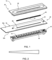
Figure 1 shows an example of a module with touch sensing functionality, in exploded form from above; -
Figure 2 shows one possible shape of the light output generated by the module; -
Figure 3 shows the module ofFigure 1 in exploded form from below; -
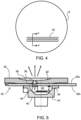
Figure 4 shows the module ofFigure 1 integrated into a surface, such as a base of a table lamp, to illustrate a first cross section; -
Figure 5 shows a cross section through one of the light sources as indicated inFigure 4 ; -
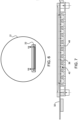
Figure 6 shows the module ofFigures 1 and3 integrated into a surface, such as a base of a table lamp, to illustrate a second cross section; -
Figure 7 shows a cross section parallel to the length of the window as indicated inFigure 6 ; -
Figure 8 shows another design of the reflector arrangement for use in the module ofFigures 1 and3 ; -
Figure 9 shows a cross section through the reflector arrangement ofFigure 8 ; -
Figure 10 shows two examples of closed shape for the window; -
Figure 11 shows lighting system in the form of a table lamp using the module; and -
Figure 12 shows a non claimed example of a rear indicator light for a vehicle using the module. - The invention will be described with reference to the Figures.
- It should be understood that the detailed description and specific examples, while indicating exemplary embodiments of the apparatus, systems and methods, are intended for purposes of illustration only and are not intended to limit the scope of the invention. These and other features, aspects, and advantages of the apparatus, systems and methods of the present invention will become better understood from the following description, appended claims, and accompanying drawings. It should be understood that the Figures are merely schematic and are not drawn to scale. It should also be understood that the same reference numerals are used throughout the Figures to indicate the same or similar parts.
- The invention provides a module comprising a carrier having a top surface and an opposite bottom surface and an elongate array of light sources on the bottom surface of the carrier. A reflector arrangement reflects light from the array of light sources along a light path towards a window to escape from the top surface. A portion of the light path is parallel to the carrier (i.e. in a sideways direction) so that the depth of the module is reduced.
- As a minimum, the module of the invention comprises a light source array mounted on a carrier and a reflector arrangement.
- One application of particular interest is for an illuminated user interface, in which there is also a touch sensor system, and the touch area is illuminated as a function of the setting selected by the user.
-
Figure 1 shows an example of a module with this touch sensing functionality. - The
module 10 comprises alight source unit 30 comprising acarrier 32 having atop surface 32a and an oppositebottom surface 32b. The carrier is in this example a printed circuit board. Anelongate window 38 is formed in the carrier formed as a slit. This window is an opening through the carrier, but it may instead be an open area adjacent an edge of thecarrier 32. - The
light source unit 30 further comprises an elongate array of light sources such as LEDs provided on thebottom surface 32b of thecarrier 32. - Beneath the carrier, there is a
reflector arrangement 40 for reflecting light from the array of light sources back towards thewindow 38, so that the light can escape from thetop surface 32a. - The
reflector arrangement 40 functions as a light guide. Light enters the light guide from the light sources, and the light escapes from the light guide to the top surface of thecarrier 30 through thewindow 38. The window thus provides a light path through the carrier, so that the carrier can be opaque, and the light output is confined to the area formed by thewindow 38. The width of the light effect is controlled by the width of thewindow 38 and thediffuser 50. The lighting effect may have a constant width along the window or it may have a width which varies along the length of the window, for example as shown inFigure 2 . - Returning to
Figure 1 , within the reflector arrangement, a light path is formed between the light sources and thewindow 38. At least part of this light path is parallel to thecarrier 32, so that part of the length of the light path is implemented as laterally directed light, which does not take up depth of the module. - The light sources are turned on in response to a control signal, in particular so that a desired length of an illuminated line (along the window) can be selected. Dynamic lighting effects can also be created.
- The reflector arrangement comprises a line of reflecting
cavities 42 together forming a cavity arrangement, discussed further below. - The
light source unit 30 and reflector arrangement are the minimum parts needed to provide a light output system. However,Figure 1 additionally shows adiffuser 50 for mounting in or over thewindow 38 for diffusing the reflected light. The downward or lateral light output by the light sources is thus reflected and passed through the diffuser, so that the lighting delivered along the length of the window appears continuous. - In the example of
Figure 1 , thelight source unit 30 also comprises atouch sensor circuit 34 formed on thetop side 32a of thecarrier 32. In this case, the module forms a control interface for controlling another system. That other system may for example comprise a lighting system with its own main light source. The control interface may then be used for controlling the main light source, such as for controlling a dimming level. - A
user interface surface 20 is provided over thelight source unit 30, having atrack area 22 for receiving touch input from a user. Thewindow 38 in the carrier is formed beneath the track area, so that the track area is illuminated by the light sources. In the example shown, the diffuser has a mountingtab 51 with a fixing hole for fixing the diffuser to theuser interface surface 20. - The
touch sensor circuit 34 is also beneath thetrack area 22 so that the location of a touch input along the track area can be detected, by a well-known touch sensor circuit. A capacitive or resistive (pressure based) touch sensor circuit may be employed. - A controller is then adapted to control the light sources in dependence on a detected location of a touch input. In this way, a touch input may be provided to the module, and the track is illuminated to show and hence confirm the user selection that had been made.
- The light sources are for example illuminated from one end of the track area up to the detected location at which a touch input has been provided. Thus, the length of illuminated track represents a control setting, such as the brightness setting for a main lighting system. When the light output has a tapered shape as shown in
Figure 2 , the width of the end of the illuminated region also represents the brightness setting. -
Figure 3 shows the module ofFigure 1 from below. It shows theLEDs 36 at the underside of thelight source unit 30. They provide light into thereflector arrangement 40. -
Figure 4 shows the module ofFigures 1 and3 integrated into a surface, such as abase 12 of a table lamp. The illuminatedtrack area 22 is shown. -
Figure 5 shows a cross section identified as V-V inFigure 4 , perpendicular to the length of the window (i.e. across the slit). -
Figure 5 in particular shows a cross section through one of the light sources 36 (LEDs) on thebottom side 32b of the carrier, and which are spaced along the track area. Anindividual cavity area 42 of thereflector arrangement 40 is shown beneath one particularlight source 36. - In this example, the light sources emit light in a direction perpendicularly away from the
carrier 32, i.e. downward emitting LEDs are used. - This example assumes specular reflective inner surfaces of each cavity. In this example, the
cavity area 42 has a first 45 degree (or near 45 degree)side wall 44 beneath thelight source 36 and a second 45 degree (or near 45 degree)side wall 46 beneath thewindow 38. The two side walls together provide a 180 degree reflection, as two 90 degree reflections using the 45 degree side walls. Between the twoside walls carrier 32. Thus, this portion of the overall light path from thelight source 36 to thewindow 38 does not take up depth of the module. - Note that in this example, separate cavities are not essential - there could be one cavity which extends the length of the window, because the light output from each LED is directed to a respective part of the window.
- However, as described below, the surfaces of the cavity may instead be diffuse reflective to form a mixing chamber. A more uniform light illuminates the diffuser, which then determines the light output characteristics. Separate cavities, as shown, are then desired so that each LED is constrained to deliver its light output to a particular portion of the window.
- In an alternative example, the light sources can emit light laterally in a direction parallel to the carrier, e.g. using side-emitting LEDs. For a similar example using specular reflective surfaces, each
cavity area 42 then only needs a single 45 degree (or near 45 degree) side wall beneath thewindow 38, in the path of the laterally emitted light. The space between the light source and the side wall in this case defines the portion of the light path parallel to thecarrier 32. - The portion of the light path which is parallel to the
carrier 32 is for example longer than the remainder of the light path between the light sources and the window. Thus, most of the light path is implemented by sideways light which has been reflected by a highly reflective side wall. -
Figure 6 again shows the module ofFigures 1 and3 integrated into a surface, such as abase 12 of a table lamp.Figure 7 shows a cross section identified as VII-VII inFigure 4 parallel to the length of the window (i.e., along the slit). -
Figure 7 shows that the reflector arrangement comprisesseparation walls 48 betweencavity areas 42 along the length of the slit. Theseparation walls 48 isolate the light output from the different light sources so that a sharp transition may be provided between light sources that are on to light sources that are off, along the slit. Thus, a selected length of the slit may be chosen to be illuminated. The separation walls are also reflective. -
Figure 8 shows another example of reflector arrangement from above, showing the line of cavities andseparation walls 48. -
Figure 9 shows a cross section through the reflector arrangement (shown as IX-IX inFigure 8 ) and theuser interface surface 20 which carries theLEDs 36. The cavity has slopedside walls reflective base 60. The cavity also has a reflective top 62, which is defined by the underside of theuser interface surface 20. Thewindow 38 is formed in this top part of the cavity. - The cavity also has reflective end walls, shown as 64 in
Figure 8 but not visible in the cross section ofFigure 9 . Thus, there are six walls forming a generally trapezoidal prism shape and they are all reflective to form a light mixing structure. - The walls may all be diffuse reflective, and the side walls for example are sloped with an angle in the
range 20 degrees to 70 degrees. There may be a combination of specular and diffuse reflective side walls. - Thus, the reflector arrangement may implement controlled reflections towards the window, needing only one or two specular reflective side walls, or it may create a light mixing chamber with all internal surfaces being reflective but requiring less control of the light path angles to the window.
- A line of LEDs and a straight slit shaped window are shown and described above. However, the lines do not need to be straight. The window and array of light sources may form a straight line, a curved line, a closed shape or indeed any other desired shape. The width of the slit be non-uniform along its length as explained with reference to
Figure 2 , and it may have any desired shape, not limited to a gradual and uniform taper as shown inFigure 2 . Two examples of closed shape are shown inFigure 10 . - As explained above, the module is part of a control interface for another device, such as a main light source to be controlled by the control interface.
-
Figure 11 showslighting system 80 in the form of a table lamp, comprising a main light source 82 (i.e., for generating the main task lighting of the table lamp) and amodule 10 as described above. The table lamp has acontroller 70 which controls the mainlight source 82 in dependence on the detected location of a touch input. For example, thecontroller 70 controls a dimming level of the mainlight source 82 in dependence on the detected location of the touch input. - The control interface may be used for controlling any main system, and is not limited to the control of a lighting system. It may be used to provide a control setting for lighting, heating, appliance control, industrial equipment control, etc.
- As explained above, the integration of the module into a touch sensor system is only one possible application of the module. The module may itself be a main lighting system, and the control of the light sources is simply to provide a desired light output.
-
Figure 12 shows an example of arear indicator light 90 for a vehicle. It is common to provide such lighting as line of illumination rather than a single spot, and dynamic effects (in addition to simple flashing) are used to make the lighting effect more noticeable, for example with progressively increasing and decreasing lengths of illumination. - The module described above, such as the light source unit (without touch sensor function), reflector arrangement and preferably also the diffuser may be used to implement the indicator light, with a low unit depth and desired lighting uniformity.
- Variations to the disclosed embodiments can be understood and effected by those skilled in the art in practicing the claimed invention, from a study of the drawings, the disclosure and the appended claims. In the claims, the word "comprising" does not exclude other elements or steps, and the indefinite article "a" or "an" does not exclude a plurality.
- The mere fact that certain measures are recited in mutually different dependent claims does not indicate that a combination of these measures cannot be used to advantage.
- If the term "adapted to" is used in the claims or description, it is noted the term "adapted to" is intended to be equivalent to the term "configured to".
- Any reference signs in the claims should not be construed as limiting the scope.
Claims (14)
- A control interface (10) for controlling a system, comprising a module comprising:a carrier (32) having a top surface and an opposite bottom surface;an elongate window formed in, or adjacent, the carrier;an elongate array of light sources (36) on the bottom surface of the carrier;a reflector arrangement (40) for reflecting light from the array of light sources towards the window (38) to escape from the top surface, such that a light path is formed between each light source and the window (38), with a portion of the light paths being parallel to the carrier (32), wherein the light sources are adapted to be turned on in response to a control signal;wherein the module further comprises:a user interface surface (20), comprising a track area (22) for receiving touch input from a user, wherein the window is formed beneath the track area; anda touch sensor circuit (34) beneath the track area (22), wherein the touch sensitive circuit (34) comprises a touch sensor region on the top surface of the carrier (32); anda controller (70) adapted to control the light sources in dependence on a detected location of a touch input.
- The control interface (10) of claim 1, wherein the module further comprises a diffuser (50) mounted in or over the window for diffusing the reflected light.
- The control interface (10) of claim 1 or 2, wherein the reflector arrangement (40) comprises a cavity arrangement formed beneath the array of light sources.
- The control interface (10) of claim 3, wherein the cavity arrangement comprises a respective cavity area (42) beneath each light source.
- The control interface (10) of claim 4, wherein the window comprises a slit with uniform or non-uniform slit width.
- The control interface (10) of claim 5, wherein the reflector arrangement comprises separation walls (48) between the cavity areas (42) along the length of the slit.
- The control interface (10) of any one of claims 4 to 6, wherein:the light sources emit light in a direction perpendicularly away from the carrier, and each cavity area (42) has a first 45 degree side wall (44) beneath the respective light source (36) and a second 45 degree side wall (46) beneath the window (38); orthe light sources emit light laterally in a direction parallel to the carrier, and each cavity area (42) has a 45 degree side wall beneath the window (38) and in the path of the laterally emitted light.
- The control interface (10) of any one of claims 4 to 6, wherein all inner surfaces of the cavity areas are reflective to form a light mixing chamber.
- The control interface of claim 7 or 8, wherein the portion of the light path is longer than the remainder of the light path between the light sources and the window.
- The control interface (10) of any one of claims 1 to 9, wherein the array of light sources comprises an array of LEDs, and the carrier is a PCB.
- The control interface of claim 1, wherein the controller (70) is adapted to illuminate the light sources from one end of the track area up to the detected location.
- A lighting system (80) comprising:a main light source (82); anda control interface as claimed in any one of claims 1-11 for controlling the main light source of the lighting system,wherein the controller (70) is adapted to control the main light source (82) in dependence on the detected location of a touch input.
- The lighting system of claim 12, wherein the controller is adapted to control a dimming level of the main light source (82) in dependence on the detected location of the touch input.
- The lighting system of claim 12 or 13, comprising a desk lamp.
Applications Claiming Priority (3)
| Application Number | Priority Date | Filing Date | Title |
|---|---|---|---|
| CN2021094951 | 2021-05-20 | ||
| EP21195193 | 2021-09-07 | ||
| PCT/EP2022/062922 WO2022243157A1 (en) | 2021-05-20 | 2022-05-12 | A light source module functioning as a user control interface |
Publications (2)
| Publication Number | Publication Date |
|---|---|
| EP4341602A1 EP4341602A1 (en) | 2024-03-27 |
| EP4341602B1 true EP4341602B1 (en) | 2025-07-09 |
Family
ID=82016383
Family Applications (1)
| Application Number | Title | Priority Date | Filing Date |
|---|---|---|---|
| EP22729130.9A Active EP4341602B1 (en) | 2021-05-20 | 2022-05-12 | A light source module functioning as a user control interface |
Country Status (4)
| Country | Link |
|---|---|
| US (1) | US12253256B2 (en) |
| EP (1) | EP4341602B1 (en) |
| CN (1) | CN117355699A (en) |
| WO (1) | WO2022243157A1 (en) |
Family Cites Families (12)
| Publication number | Priority date | Publication date | Assignee | Title |
|---|---|---|---|---|
| US5471371A (en) * | 1993-01-08 | 1995-11-28 | Ford Motor Company | High efficiency illuminator |
| KR100836749B1 (en) * | 2008-03-17 | 2008-06-10 | 한울정보기술(주) | Emission Capacitive Touch Sensor |
| WO2012062347A1 (en) * | 2010-11-08 | 2012-05-18 | Osram Ag | Linear illumination device having leds |
| US11519585B2 (en) * | 2012-01-24 | 2022-12-06 | SMR Patent S.à.r.l. | Covering devices for use with vehicle parts |
| DE102014215329A1 (en) * | 2014-08-04 | 2016-02-04 | Volkswagen Aktiengesellschaft | Ambient light unit and method for adjusting an ambient light in a vehicle |
| US20160215964A1 (en) | 2015-01-26 | 2016-07-28 | Feit Electric Company, Inc. | Customizable Stand Lamp |
| US9389769B1 (en) | 2015-07-13 | 2016-07-12 | James Thomas O'Keeffe | Smart illuminated electrical switch with touch control |
| US10480752B2 (en) * | 2016-02-27 | 2019-11-19 | Svv Technology Innovations, Inc. | Structurally reinforced illumination panels and a method of making the same |
| JP6679392B2 (en) | 2016-04-12 | 2020-04-15 | 株式会社小糸製作所 | Manufacturing method of resin molded product and welding apparatus |
| DE102017208999B4 (en) | 2017-05-29 | 2025-09-04 | Volkswagen Aktiengesellschaft | Lighting device with a housing with a G-shaped cross-section and formed from two profiles each open on one side for illuminating the interior of a motor vehicle |
| CN110785730B (en) | 2017-06-27 | 2023-12-22 | 昕诺飞控股有限公司 | Devices, systems and methods with touch user interfaces for controlling loads |
| CN112013295A (en) | 2020-07-03 | 2020-12-01 | 上海诺视照明科技有限公司 | Desk lamp with LED arc three-dimensional light guide light source |
-
2022
- 2022-05-12 WO PCT/EP2022/062922 patent/WO2022243157A1/en not_active Ceased
- 2022-05-12 EP EP22729130.9A patent/EP4341602B1/en active Active
- 2022-05-12 US US18/562,420 patent/US12253256B2/en active Active
- 2022-05-12 CN CN202280036420.8A patent/CN117355699A/en active Pending
Also Published As
| Publication number | Publication date |
|---|---|
| CN117355699A (en) | 2024-01-05 |
| US20240247779A1 (en) | 2024-07-25 |
| EP4341602A1 (en) | 2024-03-27 |
| US12253256B2 (en) | 2025-03-18 |
| WO2022243157A1 (en) | 2022-11-24 |
Similar Documents
| Publication | Publication Date | Title |
|---|---|---|
| KR100454991B1 (en) | Illuminator with diffuser | |
| US7559664B1 (en) | Low profile backlighting using LEDs | |
| US7607808B2 (en) | Instrument panel housing with light diffuser | |
| CN107206929B (en) | The vehicle lamp assembly of vehicle | |
| US20090109649A1 (en) | System and apparatus for keyboard illumination | |
| US20180195705A1 (en) | Edge-lit lighting device | |
| CN112721633A (en) | Display for an interior of a motor vehicle | |
| US8534892B2 (en) | Controlled flaring light transmission device | |
| US12253256B2 (en) | Light source module functioning as a user control interface | |
| CN108224351B (en) | Lighting unit | |
| JP4942416B2 (en) | Kitchen counter | |
| JP2020004610A (en) | Light guide plate, light guide plate assembly, and lighting device | |
| CN207826092U (en) | A kind of light guide plate and combination instrument | |
| KR102048315B1 (en) | Lighting device and its control method | |
| CN109506199B (en) | Small-thickness lighting device capable of generating uniform illumination | |
| EP2017658A2 (en) | Illumination device | |
| CN111076492A (en) | Refrigerator with a door | |
| CN112203887A (en) | Especially display devices for vehicles | |
| JP2019067571A (en) | LED lighting unit and line type base lighting fixture | |
| EP3618665B1 (en) | Illuminated mirror | |
| US10782010B2 (en) | Edge-lit lighting fixture sensor shield | |
| CN113939684B (en) | Lighting system | |
| JP7159981B2 (en) | lighting equipment | |
| JP2010524752A (en) | In-car display | |
| KR20000051328A (en) | Backlight assembly in the thin film transistor type optical sensor |
Legal Events
| Date | Code | Title | Description |
|---|---|---|---|
| STAA | Information on the status of an ep patent application or granted ep patent |
Free format text: STATUS: UNKNOWN |
|
| STAA | Information on the status of an ep patent application or granted ep patent |
Free format text: STATUS: THE INTERNATIONAL PUBLICATION HAS BEEN MADE |
|
| PUAI | Public reference made under article 153(3) epc to a published international application that has entered the european phase |
Free format text: ORIGINAL CODE: 0009012 |
|
| STAA | Information on the status of an ep patent application or granted ep patent |
Free format text: STATUS: REQUEST FOR EXAMINATION WAS MADE |
|
| 17P | Request for examination filed |
Effective date: 20231220 |
|
| AK | Designated contracting states |
Kind code of ref document: A1 Designated state(s): AL AT BE BG CH CY CZ DE DK EE ES FI FR GB GR HR HU IE IS IT LI LT LU LV MC MK MT NL NO PL PT RO RS SE SI SK SM TR |
|
| DAV | Request for validation of the european patent (deleted) | ||
| DAX | Request for extension of the european patent (deleted) | ||
| GRAP | Despatch of communication of intention to grant a patent |
Free format text: ORIGINAL CODE: EPIDOSNIGR1 |
|
| STAA | Information on the status of an ep patent application or granted ep patent |
Free format text: STATUS: GRANT OF PATENT IS INTENDED |
|
| INTG | Intention to grant announced |
Effective date: 20250130 |
|
| GRAS | Grant fee paid |
Free format text: ORIGINAL CODE: EPIDOSNIGR3 |
|
| P01 | Opt-out of the competence of the unified patent court (upc) registered |
Free format text: CASE NUMBER: APP_18357/2025 Effective date: 20250415 |
|
| GRAA | (expected) grant |
Free format text: ORIGINAL CODE: 0009210 |
|
| STAA | Information on the status of an ep patent application or granted ep patent |
Free format text: STATUS: THE PATENT HAS BEEN GRANTED |
|
| AK | Designated contracting states |
Kind code of ref document: B1 Designated state(s): AL AT BE BG CH CY CZ DE DK EE ES FI FR GB GR HR HU IE IS IT LI LT LU LV MC MK MT NL NO PL PT RO RS SE SI SK SM TR |
|
| REG | Reference to a national code |
Ref country code: GB Ref legal event code: FG4D |
|
| REG | Reference to a national code |
Ref country code: CH Ref legal event code: EP |
|
| REG | Reference to a national code |
Ref country code: IE Ref legal event code: FG4D |
|
| REG | Reference to a national code |
Ref country code: DE Ref legal event code: R096 Ref document number: 602022017339 Country of ref document: DE |
|
| REG | Reference to a national code |
Ref country code: NL Ref legal event code: MP Effective date: 20250709 |
|
| PG25 | Lapsed in a contracting state [announced via postgrant information from national office to epo] |
Ref country code: PT Free format text: LAPSE BECAUSE OF FAILURE TO SUBMIT A TRANSLATION OF THE DESCRIPTION OR TO PAY THE FEE WITHIN THE PRESCRIBED TIME-LIMIT Effective date: 20251110 |
|
| PG25 | Lapsed in a contracting state [announced via postgrant information from national office to epo] |
Ref country code: NL Free format text: LAPSE BECAUSE OF FAILURE TO SUBMIT A TRANSLATION OF THE DESCRIPTION OR TO PAY THE FEE WITHIN THE PRESCRIBED TIME-LIMIT Effective date: 20250709 |
|
| REG | Reference to a national code |
Ref country code: AT Ref legal event code: MK05 Ref document number: 1812096 Country of ref document: AT Kind code of ref document: T Effective date: 20250709 |
|
| PG25 | Lapsed in a contracting state [announced via postgrant information from national office to epo] |
Ref country code: IS Free format text: LAPSE BECAUSE OF FAILURE TO SUBMIT A TRANSLATION OF THE DESCRIPTION OR TO PAY THE FEE WITHIN THE PRESCRIBED TIME-LIMIT Effective date: 20251109 |
|
| PG25 | Lapsed in a contracting state [announced via postgrant information from national office to epo] |
Ref country code: NO Free format text: LAPSE BECAUSE OF FAILURE TO SUBMIT A TRANSLATION OF THE DESCRIPTION OR TO PAY THE FEE WITHIN THE PRESCRIBED TIME-LIMIT Effective date: 20251009 |
|
| REG | Reference to a national code |
Ref country code: LT Ref legal event code: MG9D |
|
| PG25 | Lapsed in a contracting state [announced via postgrant information from national office to epo] |
Ref country code: AT Free format text: LAPSE BECAUSE OF FAILURE TO SUBMIT A TRANSLATION OF THE DESCRIPTION OR TO PAY THE FEE WITHIN THE PRESCRIBED TIME-LIMIT Effective date: 20250709 |
|
| PG25 | Lapsed in a contracting state [announced via postgrant information from national office to epo] |
Ref country code: FI Free format text: LAPSE BECAUSE OF FAILURE TO SUBMIT A TRANSLATION OF THE DESCRIPTION OR TO PAY THE FEE WITHIN THE PRESCRIBED TIME-LIMIT Effective date: 20250709 |
|
| PG25 | Lapsed in a contracting state [announced via postgrant information from national office to epo] |
Ref country code: HR Free format text: LAPSE BECAUSE OF FAILURE TO SUBMIT A TRANSLATION OF THE DESCRIPTION OR TO PAY THE FEE WITHIN THE PRESCRIBED TIME-LIMIT Effective date: 20250709 |
|
| PG25 | Lapsed in a contracting state [announced via postgrant information from national office to epo] |
Ref country code: GR Free format text: LAPSE BECAUSE OF FAILURE TO SUBMIT A TRANSLATION OF THE DESCRIPTION OR TO PAY THE FEE WITHIN THE PRESCRIBED TIME-LIMIT Effective date: 20251010 |
|
| PG25 | Lapsed in a contracting state [announced via postgrant information from national office to epo] |
Ref country code: SE Free format text: LAPSE BECAUSE OF FAILURE TO SUBMIT A TRANSLATION OF THE DESCRIPTION OR TO PAY THE FEE WITHIN THE PRESCRIBED TIME-LIMIT Effective date: 20250709 |
|
| PG25 | Lapsed in a contracting state [announced via postgrant information from national office to epo] |
Ref country code: LV Free format text: LAPSE BECAUSE OF FAILURE TO SUBMIT A TRANSLATION OF THE DESCRIPTION OR TO PAY THE FEE WITHIN THE PRESCRIBED TIME-LIMIT Effective date: 20250709 |
|
| PG25 | Lapsed in a contracting state [announced via postgrant information from national office to epo] |
Ref country code: PL Free format text: LAPSE BECAUSE OF FAILURE TO SUBMIT A TRANSLATION OF THE DESCRIPTION OR TO PAY THE FEE WITHIN THE PRESCRIBED TIME-LIMIT Effective date: 20250709 Ref country code: BG Free format text: LAPSE BECAUSE OF FAILURE TO SUBMIT A TRANSLATION OF THE DESCRIPTION OR TO PAY THE FEE WITHIN THE PRESCRIBED TIME-LIMIT Effective date: 20250709 |
|
| PG25 | Lapsed in a contracting state [announced via postgrant information from national office to epo] |
Ref country code: RS Free format text: LAPSE BECAUSE OF FAILURE TO SUBMIT A TRANSLATION OF THE DESCRIPTION OR TO PAY THE FEE WITHIN THE PRESCRIBED TIME-LIMIT Effective date: 20251009 |
|
| PG25 | Lapsed in a contracting state [announced via postgrant information from national office to epo] |
Ref country code: ES Free format text: LAPSE BECAUSE OF FAILURE TO SUBMIT A TRANSLATION OF THE DESCRIPTION OR TO PAY THE FEE WITHIN THE PRESCRIBED TIME-LIMIT Effective date: 20250709 |
|
| PG25 | Lapsed in a contracting state [announced via postgrant information from national office to epo] |
Ref country code: SM Free format text: LAPSE BECAUSE OF FAILURE TO SUBMIT A TRANSLATION OF THE DESCRIPTION OR TO PAY THE FEE WITHIN THE PRESCRIBED TIME-LIMIT Effective date: 20250709 |
|
| PGFP | Annual fee paid to national office [announced via postgrant information from national office to epo] |
Ref country code: GB Payment date: 20260304 Year of fee payment: 5 |
|
| REG | Reference to a national code |
Ref country code: DE Ref legal event code: R097 Ref document number: 602022017339 Country of ref document: DE |
|
| PG25 | Lapsed in a contracting state [announced via postgrant information from national office to epo] |
Ref country code: DK Free format text: LAPSE BECAUSE OF FAILURE TO SUBMIT A TRANSLATION OF THE DESCRIPTION OR TO PAY THE FEE WITHIN THE PRESCRIBED TIME-LIMIT Effective date: 20250709 |
|
| PG25 | Lapsed in a contracting state [announced via postgrant information from national office to epo] |
Ref country code: IT Free format text: LAPSE BECAUSE OF FAILURE TO SUBMIT A TRANSLATION OF THE DESCRIPTION OR TO PAY THE FEE WITHIN THE PRESCRIBED TIME-LIMIT Effective date: 20250709 |
|
| PG25 | Lapsed in a contracting state [announced via postgrant information from national office to epo] |
Ref country code: CZ Free format text: LAPSE BECAUSE OF FAILURE TO SUBMIT A TRANSLATION OF THE DESCRIPTION OR TO PAY THE FEE WITHIN THE PRESCRIBED TIME-LIMIT Effective date: 20250709 |
|
| PG25 | Lapsed in a contracting state [announced via postgrant information from national office to epo] |
Ref country code: SK Free format text: LAPSE BECAUSE OF FAILURE TO SUBMIT A TRANSLATION OF THE DESCRIPTION OR TO PAY THE FEE WITHIN THE PRESCRIBED TIME-LIMIT Effective date: 20250709 Ref country code: EE Free format text: LAPSE BECAUSE OF FAILURE TO SUBMIT A TRANSLATION OF THE DESCRIPTION OR TO PAY THE FEE WITHIN THE PRESCRIBED TIME-LIMIT Effective date: 20250709 |
|
| PLBE | No opposition filed within time limit |
Free format text: ORIGINAL CODE: 0009261 |
|
| STAA | Information on the status of an ep patent application or granted ep patent |
Free format text: STATUS: NO OPPOSITION FILED WITHIN TIME LIMIT |
|
| REG | Reference to a national code |
Ref country code: CH Ref legal event code: L10 Free format text: ST27 STATUS EVENT CODE: U-0-0-L10-L00 (AS PROVIDED BY THE NATIONAL OFFICE) Effective date: 20260521 |
|
| 26N | No opposition filed |
Effective date: 20260410 |
|
| PG25 | Lapsed in a contracting state [announced via postgrant information from national office to epo] |
Ref country code: LT Free format text: LAPSE BECAUSE OF FAILURE TO SUBMIT A TRANSLATION OF THE DESCRIPTION OR TO PAY THE FEE WITHIN THE PRESCRIBED TIME-LIMIT Effective date: 20250709 |
|
| PGFP | Annual fee paid to national office [announced via postgrant information from national office to epo] |
Ref country code: FR Payment date: 20260521 Year of fee payment: 5 |