EP4340727B1 - Ct beam hardening correction method, ct beam hardening correction device, and storage medium - Google Patents
Ct beam hardening correction method, ct beam hardening correction device, and storage medium Download PDFInfo
- Publication number
- EP4340727B1 EP4340727B1 EP21778343.0A EP21778343A EP4340727B1 EP 4340727 B1 EP4340727 B1 EP 4340727B1 EP 21778343 A EP21778343 A EP 21778343A EP 4340727 B1 EP4340727 B1 EP 4340727B1
- Authority
- EP
- European Patent Office
- Prior art keywords
- projection data
- phantom
- hardening correction
- measured
- beam hardening
- Prior art date
- Legal status (The legal status is an assumption and is not a legal conclusion. Google has not performed a legal analysis and makes no representation as to the accuracy of the status listed.)
- Active
Links
Images



Classifications
-
- G—PHYSICS
- G06—COMPUTING OR CALCULATING; COUNTING
- G06T—IMAGE DATA PROCESSING OR GENERATION, IN GENERAL
- G06T12/00—Tomographic reconstruction from projections
- G06T12/10—Image preprocessing, e.g. calibration, positioning of sources or scatter correction
-
- A—HUMAN NECESSITIES
- A61—MEDICAL OR VETERINARY SCIENCE; HYGIENE
- A61B—DIAGNOSIS; SURGERY; IDENTIFICATION
- A61B6/00—Apparatus or devices for radiation diagnosis; Apparatus or devices for radiation diagnosis combined with radiation therapy equipment
- A61B6/02—Arrangements for diagnosis sequentially in different planes; Stereoscopic radiation diagnosis
- A61B6/03—Computed tomography [CT]
- A61B6/032—Transmission computed tomography [CT]
-
- A—HUMAN NECESSITIES
- A61—MEDICAL OR VETERINARY SCIENCE; HYGIENE
- A61B—DIAGNOSIS; SURGERY; IDENTIFICATION
- A61B6/00—Apparatus or devices for radiation diagnosis; Apparatus or devices for radiation diagnosis combined with radiation therapy equipment
- A61B6/52—Devices using data or image processing specially adapted for radiation diagnosis
-
- A—HUMAN NECESSITIES
- A61—MEDICAL OR VETERINARY SCIENCE; HYGIENE
- A61B—DIAGNOSIS; SURGERY; IDENTIFICATION
- A61B6/00—Apparatus or devices for radiation diagnosis; Apparatus or devices for radiation diagnosis combined with radiation therapy equipment
- A61B6/52—Devices using data or image processing specially adapted for radiation diagnosis
- A61B6/5258—Devices using data or image processing specially adapted for radiation diagnosis involving detection or reduction of artifacts or noise
-
- A—HUMAN NECESSITIES
- A61—MEDICAL OR VETERINARY SCIENCE; HYGIENE
- A61B—DIAGNOSIS; SURGERY; IDENTIFICATION
- A61B6/00—Apparatus or devices for radiation diagnosis; Apparatus or devices for radiation diagnosis combined with radiation therapy equipment
- A61B6/58—Testing, adjusting or calibrating thereof
- A61B6/582—Calibration
- A61B6/583—Calibration using calibration phantoms
Definitions
- the present invention relates to the technical field of CT devices, and in particular, a projection-based CT beam hardening correction method, a CT beam hardening correction device, and a storage medium.
- X-rays are produced in bremsstrahlung effects and contain broad spectral components. Since low energy X-rays have relatively high attenuation coefficients and are easily absorbed, low energy X-rays attenuate more when passing through objects, and X-ray spectra become "harder" after passing through objects. This means that the proportion of high energy X-rays detected by a detector increases, resulting in a smaller projection value. Because of the beam hardening effect, the attenuation coefficient along the X-ray path is not constant, and this will result in inhomogeneity even in a CT image of a uniform object.
- a beam filter may be used to reduce low energy X-rays and increase the average energy of the beam.
- the beam filter will reduce the dose and thus require a higher scanning tube power output, and it will increase the average energy of the X-ray beam and affect low contrast detectability. In addition, it still fails to meet the CT image quality requirements in most clinical scenarios.
- a polynomial fitting correction algorithm is generally applied based on a water phantom. Because water is a main component of a human body, and most beam hardening correction algorithms need to determine polynomial factors for each system, most existing methods for determining a polynomial factor need to determine the polynomial factors in an iterative manner or based on image reconstruction. Since the iterative process and/or image reconstruction are usually inefficient, the entire beam hardening correction process is quite time consuming. Due to time costs, it is difficult or almost impossible to perform the entire correction process for each system.
- US 2014/321608 A1 discloses that in X-ray CT devices, degradation of quantitative determination ability for CT values resulting from the beam hardening (BH) effect of X-ray is prevented.
- X-ray absorption characteristic S obtained by simulation and a target value T thereof are saved beforehand, the simulation value S is revised by using projection data measured by maintenance measurement for obtaining basic data required for BH correction, and a BH correction coefficient is calculated by using the revised X-ray absorption characteristic S and the target value T.
- BH correction accuracy can be improved, and reduction of incorrect diagnosis resulting from inhomogeneity of the CT values and improvement in the diagnostic ability based on improvement in quantitative determination ability for the CT values can be realized.
- the present invention proposes a CT beam hardening correction method, a CT beam hardening correction device, and a storage medium.
- One purpose thereof is to calculate a beam hardening factor by using only projection data of a scanned object without having to perform image reconstruction before calculating the beam hardening factor or iteration, thereby improving calculation efficiency, so that such correction method can be applied to each system in a tuning process of a CT device without adding extra time.
- a CT beam hardening correction method including: scanning a plurality of phantoms of different sizes by using a beam emitted by a ray source of a CT device, to obtain measured projection data of the plurality of phantoms; calculating estimated theoretical projection data of each phantom based on an initial estimated position of the phantom relative to the ray source by using a theoretical projection data calculation model; calculating an actual position of each phantom relative to the ray source based on the measured projection data of the phantom and the estimated theoretical projection data of the phantom; calculating actual theoretical projection data of each phantom by using the theoretical projection data calculation model according to the actual position of the phantom relative to the ray source; obtaining a beam hardening correction calculation model, where the beam hardening correction calculation model represents a relationship among expected projection data of a scanned object, measured projection data of the scanned object, and a beam hardening correction factor; using the
- the beam hardening factor can be calculated by using only the projection data of the scanned phantom without performing image reconstruction before the beam hardening factor is calculated and a reconstruction process, thereby improving calculation efficiency, so that such method can be applied to each system in a tuning process of a CT device without adding extra time.
- the polynomial expression of the beam hardening correction model is preset, and then the beam hardening correction factor is obtained according to the actual theoretical projection data of the phantom and the measured projection data of the phantom.
- the method in this application can avoid image reconstruction and iterative processes, and can be applied to each system in a tuning process of a CT device without adding extra time.
- the calculating the beam hardening correction factor according to the relationship includes: substituting the actual theoretical projection data P sim of each phantom as the expected projection data of the scanned object, and the measured projection data P of each phantom as the measured projection data of the scanned object into the polynomial expression of the beam hardening correction calculation model to obtain the following expression (1):
- V i,j P ⁇ ( P + B ) i ⁇ B j
- Attenuation of a unit distance between a high-energy ray and a low-energy ray in a beam emitted by the ray source along an X-ray path is basically the same, so that an image reconstructed from projection data detected by a detector (array) has little beam hardening artifact.
- the ray source is a scanning tube
- the total amount N of the pixel data is equal to the quantity of the phantoms ⁇ the quantity of positions of the phantoms ⁇ the quantity of scanning positions of the scanning tube ⁇ the quantity of the detector pixels.
- the beam hardening correction method in this application can be made more robust, and can be adapted to measured objects of different sizes, for example, adults and children of different heights.
- the scanning tube performs scanning at a predetermined angle interval, preferably, the predetermined angle interval may be ⁇ /6.
- the measured projection data of the plurality of phantoms includes measured projection data obtained by scanning each phantom at a plurality of phantom positions of the phantom and a plurality of scanning spherical tube positions.
- the beam hardening correction method in this application can be more robust.
- the theoretical projection data of the phantom can be determined by using a simple calculation process.
- the initial estimated position of each phantom relative to the ray source of the beam includes an initial estimated distance D' between the ray source of the beam and the center of the phantom and an initial estimated angle ⁇ 0 ' between the line connecting the ray source of the beam and the center of the phantom and the center line of the beam
- the calculating estimated theoretical projection data of each phantom based on an initial estimated position of the phantom relative to the ray source of the beam by using a theoretical projection data calculation model includes: presetting the initial estimated distance D' and the initial estimated angle ⁇ 0 '; and substituting the initial estimated distance D' as the distance D between the ray source of the beam and the center of the phantom and the initial estimated angle ⁇ 0 ' as the angle ⁇ 0 between the line connecting the ray source of the beam and the center of the phantom and the center line of the beam into the theoretical projection data calculation model to calculate the estimated theoretical projection data.
- the initial estimated position of each phantom relative to the ray source of the beam is estimated according to experience, and the theoretical projection data is estimated according to the initial estimated position, thereby simplifying a calculation process.
- the actual position of each phantom relative to the ray source of the beam includes an actual distance D" between the ray source of the beam and the center of the phantom and an actual angle ⁇ 0 " between the line connecting the ray source of the beam and the center of the phantom and the center line of the beam
- the calculating an actual position of each phantom relative to the ray source of the beam based on the measured projection data of the phantom and the estimated theoretical projection data of the phantom includes: determining the actual distance D" and the actual angle ⁇ 0 " by minimizing the sum of the differences of squares of the measured projection data and the calculated estimated theoretical projection data by using a simplex multi-parameter optimization method.
- the initial estimated position of each phantom relative to the ray source of the beam can be corrected based on the measured projection data of the phantom, and therefore, the actual position of each phantom relative to the ray source of the beam can be accurately determined.
- the calculating actual theoretical projection data of each phantom by using the theoretical projection data calculation model according to the actual position of the phantom relative to the ray source of the beam includes: substituting the determined actual distance D" as the distance D between the ray source of the beam and the center of the phantom and the actual angle ⁇ 0 " as the angle ⁇ 0 between the line connecting the ray source of the beam and the center of the phantom and the center line of the beam into the theoretical projection data calculation model to calculate the actual theoretical projection data of each phantom.
- a CT beam hardening correction device including: an estimated theoretical projection data calculation module, configured to calculate estimated theoretical projection data of each phantom based on an initial estimated position of the phantom relative to the ray source by using a theoretical projection data calculation model; a phantom actual position calculation module, configured to calculate an actual position of each phantom relative to the ray source of the beam based on measured projection data of each phantom obtained by scanning a plurality of phantoms of different sizes by using a beam emitted by a CT device and the estimated theoretical projection data of each phantom; an actual theoretical projection data calculation module, configured to calculate actual theoretical projection data of each phantom by using the theoretical projection data calculation model according to the actual position of the phantom relative to the ray source of the beam; a beam hardening correction calculation model obtaining module, configured to obtain a beam hardening correction calculation model, where the beam hardening correction calculation model represents a relationship among expected projection
- the beam hardening factor can be calculated by using only the projection data of the scanned object without performing image reconstruction before the beam hardening factor is calculated, and no iterative process is required in the calculation process. Therefore, calculation efficiency can be improved, so that such correction method can be applied to each system in a tuning process of a CT device without adding extra time.
- a storage medium storing a program.
- the program causes the processor to perform the foregoing CT beam hardening correction method.
- the beam hardening factor can be calculated by using only the projection data of the scanned object without performing image reconstruction before the beam hardening factor is calculated, and no iterative process is required in the calculation process. Therefore, calculation efficiency can be improved, so that such correction method can be applied to each system in a tuning process of a CT device without adding extra time.
- FIG. 1 is a flowchart of a CT beam hardening correction method according to an embodiment of this disclosure.
- the CT beam hardening correction method according to this embodiment of the present disclosure includes the following steps: Step S 100: Scan a plurality of phantoms of different sizes by using a beam emitted by a ray source of a CT device, to obtain measured projection data of the plurality of phantoms.
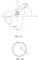
- the ray source may include a scanning tube, and the scanning tube may scan the phantom at a predetermined angle interval ⁇ (as shown in FIG. 2A ), for example, an angle interval ⁇ /6; and may scan each phantom relative to the ray source at different positions of the CT device.
- the phantom may be scanned in a rotation center, and the phantom may be eccentrically scanned. Therefore, the measured projection data of the plurality of phantoms includes measured projection data obtained by scanning each phantom at a plurality of phantom positions of the phantom and a plurality of scanning tube positions.
- Step S101 Calculate estimated theoretical projection data of each phantom based on an initial estimated position of the phantom relative to the ray source by using a theoretical projection data calculation model (in FIG. 2A , the ray source is an X-ray scanning tube, and the scanning tube is represented by a focal point thereof).
- a theoretical projection data calculation model in FIG. 2A , the ray source is an X-ray scanning tube, and the scanning tube is represented by a focal point thereof).
- the phantom may be a water phantom for simulating a human body.
- the housing of the phantom is made of PMMA materials, and the filler in the housing is water.
- projection data is used to indicate the attenuation amount.
- the initial estimated position of each phantom relative to the ray source of the beam includes an initial estimated distance D' between the ray source of the beam and the center of the phantom and an initial estimated angle ⁇ 0 ' between the line connecting the ray source of the beam and the center of the phantom and the center line of the beam, and the initial estimated distance D' and the initial estimated angle ⁇ 0 ' may be initially set.
- Step S102 Calculate an actual position of each phantom relative to the ray source the beam based on the measured projection data of the phantom and the estimated theoretical projection data of the phantom.
- the actual position of each phantom relative to the ray source of the beam includes an actual distance D" between the ray source of the beam and the center of the phantom and an actual angle ⁇ 0 " between the line connecting the ray source of the beam and the center of the phantom and the center line of the beam, and the actual distance D" and the actual angle ⁇ 0 " are determined by minimizing the sum of the differences of squares of the measured projection data (measured attenuation amount) of the phantom shown in FIG. 3 and the calculated estimated theoretical projection data (estimated theoretical attenuation amount) by using a simplex multi-parameter optimization method.
- Step S103 Calculate actual theoretical projection data of each phantom by using the theoretical projection data calculation model according to the actual position of the phantom relative to the ray source of the beam.
- the determined actual distance D" as the distance D between the ray source of the beam and the center of the phantom and the actual angle ⁇ 0 " as the angle ⁇ 0 between the line connecting the ray source of the beam and the center of the phantom and the center line of the beam are substituted into the theoretical projection data calculation model to calculate the actual theoretical projection data of each phantom.
- step S104 it is determined at step S104 whether the foregoing steps S100-S103 have been performed for all the phantoms and all the positions of the phantoms. If yes, step S105 is performed. If no, step S100 is performed.
- Step S105 Obtain a beam hardening correction calculation model, where the beam hardening correction calculation model represents a relationship among expected projection data of a scanned object, measured projection data of the scanned object, and a beam hardening correction factor.
- Step S106 Use the actual theoretical projection data of each phantom as the expected projection data of the scanned object, use the measured projection data of each phantom as the measured projection data of the scanned object, and calculate the beam hardening correction factor according to the relationship by using the beam hardening correction calculation model.
- the matrix calculation formula is solved by using the least square method to calculate the beam hardening correction factor f i,j , where k is a detector pixel index and N is the total amount of pixel data.
- the ray source may be a scanning tube, and the total amount N of the pixel data is equal to the quantity of the phantoms ⁇ the quantity of positions of the phantoms ⁇ the quantity of scanning positions of the scanning tube ⁇ the quantity of the detector pixels.
- the scanning tube may perform scanning at a predetermined angle interval such as ⁇ /6, so that calculation time can be reduced.
- Step S107 Use measured projection data of a measured object as the measured projection data of the scanned object and corrected projection data of the measured object as the expected projection data of the scanned object based on the calculated beam hardening correction factor, and calculate the corrected projection data of the measured object according to the relationship.
- the measured projection data P 1 of the measured object as the measured projection data of the scanned object and the corrected projection data P BHC of the measured object as the expected projection data of the scanned object are substituted into the polynomial expression of the beam hardening correction calculation model to obtain the following expression (2):
- the corrected projection data P BHC of the measured object is calculated based on the calculated beam hardening correction factor f i,j and the measured projection data P 1 of the measured object by using expression (2).
- the foregoing CT beam hardening correction method in this application may be applied to rotation scanning and static scanning, and the foregoing CT beam hardening correction method is further applicable to various phantoms that are equivalent to human tissues and have a known attenuation coefficient.
- FIG. 5 shows measured projection data of a 20 cm water phantom and a 30 cm water phantom of a measured object, a graph of corrected projection data obtained after the measured projection data of the 20 cm water phantom and the 30 cm water phantom of the measured object are corrected by using the CT beam hardening correction method provided in the embodiment of the present disclosure, and an instance of a constructed image.
- the maximum average difference between the peripheral region of interest (ROI) and the central ROI of the 20 cm water phantom is less than 1 Hounsfield unit (HU, used for CT image measurement, which may also be referred to as a CT value), and the maximum average difference between the peripheral ROI and the central ROI of the 30 cm water phantom is about 1 HU, which can clearly meet a uniformity requirement of a CT factory delivery system.
- HU Hounsfield unit
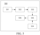
- FIG. 5 shows a CT beam hardening correction device 500 corresponding to the CT beam hardening correction method in FIG. 1 .
- the CT beam hardening correction device 500 performs steps of the CT beam hardening correction method in FIG. 1 .
- the CT beam hardening correction device 500 may include: an estimated theoretical projection data calculation module 501, configured to receive an initially set initial estimated position of each phantom relative to a ray source of a beam, and calculate estimated theoretical projection data of each phantom based on the initial estimated position of the phantom relative to the ray source by using a theoretical projection data calculation model; a phantom actual position calculation module 502, configured to receive from a detector (array) measured projection data of each phantom obtained by scanning a plurality of phantoms of different sizes by using a beam emitted by a ray source of a CT device, receive the estimated theoretical projection data of each phantom from the estimated theoretical projection data calculation module 501, and calculate an actual position of each phantom
- the beam hardening correction method in this application may be stored in a computer storage medium as a program, and a processor may read the program from the computer storage medium and execute the program, so as to perform the beam hardening correction method.
Landscapes
- Health & Medical Sciences (AREA)
- Life Sciences & Earth Sciences (AREA)
- Engineering & Computer Science (AREA)
- Medical Informatics (AREA)
- Physics & Mathematics (AREA)
- Biomedical Technology (AREA)
- Molecular Biology (AREA)
- Biophysics (AREA)
- Nuclear Medicine, Radiotherapy & Molecular Imaging (AREA)
- Optics & Photonics (AREA)
- Pathology (AREA)
- Radiology & Medical Imaging (AREA)
- Veterinary Medicine (AREA)
- Heart & Thoracic Surgery (AREA)
- High Energy & Nuclear Physics (AREA)
- Surgery (AREA)
- Animal Behavior & Ethology (AREA)
- General Health & Medical Sciences (AREA)
- Public Health (AREA)
- Computer Vision & Pattern Recognition (AREA)
- Theoretical Computer Science (AREA)
- Pulmonology (AREA)
- General Physics & Mathematics (AREA)
- Apparatus For Radiation Diagnosis (AREA)
Description
- The present invention relates to the technical field of CT devices, and in particular, a projection-based CT beam hardening correction method, a CT beam hardening correction device, and a storage medium.
- In general, X-rays are produced in bremsstrahlung effects and contain broad spectral components. Since low energy X-rays have relatively high attenuation coefficients and are easily absorbed, low energy X-rays attenuate more when passing through objects, and X-ray spectra become "harder" after passing through objects. This means that the proportion of high energy X-rays detected by a detector increases, resulting in a smaller projection value. Because of the beam hardening effect, the attenuation coefficient along the X-ray path is not constant, and this will result in inhomogeneity even in a CT image of a uniform object.
- To compensate for this effect, a beam filter may be used to reduce low energy X-rays and increase the average energy of the beam. However, the beam filter will reduce the dose and thus require a higher scanning tube power output, and it will increase the average energy of the X-ray beam and affect low contrast detectability. In addition, it still fails to meet the CT image quality requirements in most clinical scenarios.
- In the prior art, in a beam hardening correction method for a CT device, a polynomial fitting correction algorithm is generally applied based on a water phantom. Because water is a main component of a human body, and most beam hardening correction algorithms need to determine polynomial factors for each system, most existing methods for determining a polynomial factor need to determine the polynomial factors in an iterative manner or based on image reconstruction. Since the iterative process and/or image reconstruction are usually inefficient, the entire beam hardening correction process is quite time consuming. Due to time costs, it is difficult or almost impossible to perform the entire correction process for each system.
- Therefore, it is desirable to use an effective method to obtain these factors.
-
US 2014/321608 A1 discloses that in X-ray CT devices, degradation of quantitative determination ability for CT values resulting from the beam hardening (BH) effect of X-ray is prevented. X-ray absorption characteristic S obtained by simulation and a target value T thereof are saved beforehand, the simulation value S is revised by using projection data measured by maintenance measurement for obtaining basic data required for BH correction, and a BH correction coefficient is calculated by using the revised X-ray absorption characteristic S and the target value T. With a few actually measured values, BH correction accuracy can be improved, and reduction of incorrect diagnosis resulting from inhomogeneity of the CT values and improvement in the diagnostic ability based on improvement in quantitative determination ability for the CT values can be realized. - In view of this, the present invention proposes a CT beam hardening correction method, a CT beam hardening correction device, and a storage medium. One purpose thereof is to calculate a beam hardening factor by using only projection data of a scanned object without having to perform image reconstruction before calculating the beam hardening factor or iteration, thereby improving calculation efficiency, so that such correction method can be applied to each system in a tuning process of a CT device without adding extra time.
- According to one aspect of embodiments of the present disclosure, a CT beam hardening correction method is provided, including: scanning a plurality of phantoms of different sizes by using a beam emitted by a ray source of a CT device, to obtain measured projection data of the plurality of phantoms; calculating estimated theoretical projection data of each phantom based on an initial estimated position of the phantom relative to the ray source by using a theoretical projection data calculation model; calculating an actual position of each phantom relative to the ray source based on the measured projection data of the phantom and the estimated theoretical projection data of the phantom; calculating actual theoretical projection data of each phantom by using the theoretical projection data calculation model according to the actual position of the phantom relative to the ray source; obtaining a beam hardening correction calculation model, where the beam hardening correction calculation model represents a relationship among expected projection data of a scanned object, measured projection data of the scanned object, and a beam hardening correction factor; using the actual theoretical projection data of each phantom as the expected projection data of the scanned object, using the measured projection data of each phantom as the measured projection data of the scanned object, and calculating the beam hardening correction factor according to the relationship by using the beam hardening correction calculation model; and using measured projection data of a measured object as the measured projection data of the scanned object and corrected projection data of the measured object as the expected projection data of the scanned object based on the calculated beam hardening correction factor, and calculating the corrected projection data of the measured object according to the relationship.
- In this way, the beam hardening factor can be calculated by using only the projection data of the scanned phantom without performing image reconstruction before the beam hardening factor is calculated and a reconstruction process, thereby improving calculation efficiency, so that such method can be applied to each system in a tuning process of a CT device without adding extra time.
- In an example according to this embodiment, the beam hardening correction calculation model is represented by the following polynomial expression:

- In this manner, the polynomial expression of the beam hardening correction model is preset, and then the beam hardening correction factor is obtained according to the actual theoretical projection data of the phantom and the measured projection data of the phantom. Compared with a conventional method in which a polynomial factor is obtained by using an image obtained by scanning a homogeneous phantom and the polynomial factor is solved in an iterative manner, the method in this application can avoid image reconstruction and iterative processes, and can be applied to each system in a tuning process of a CT device without adding extra time.
- In an example of this embodiment, the calculating the beam hardening correction factor according to the relationship includes: substituting the actual theoretical projection data Psim of each phantom as the expected projection data of the scanned object, and the measured projection data P of each phantom as the measured projection data of the scanned object into the polynomial expression of the beam hardening correction calculation model to obtain the following expression (1):


- In this manner, calculation complexity of the beam hardening correction factor f i,j can be simplified and accuracy of determining the beam hardening correction factor f i,j can be improved.
- In an example of this embodiment, the calculating corrected projection data of the measured object according to the relationship includes: substituting the measured projection data P1 of the measured object as the measured projection data of the scanned object and the corrected projection data PBHC of the measured object as the expected projection data of the scanned object into the polynomial expression of the beam hardening correction calculation model to obtain the following expression (2):

- In this manner, attenuation of a unit distance between a high-energy ray and a low-energy ray in a beam emitted by the ray source along an X-ray path is basically the same, so that an image reconstructed from projection data detected by a detector (array) has little beam hardening artifact.
- In an example according to this embodiment, the ray source is a scanning tube, and the total amount N of the pixel data is equal to the quantity of the phantoms × the quantity of positions of the phantoms × the quantity of scanning positions of the scanning tube × the quantity of the detector pixels.
- In this manner, the beam hardening correction method in this application can be made more robust, and can be adapted to measured objects of different sizes, for example, adults and children of different heights.
- In an example according to this embodiment, the scanning tube performs scanning at a predetermined angle interval, preferably, the predetermined angle interval may be π/6.
- In this manner, calculation time can be reduced.
- In an example according to this embodiment, the measured projection data of the plurality of phantoms includes measured projection data obtained by scanning each phantom at a plurality of phantom positions of the phantom and a plurality of scanning spherical tube positions.
- In this manner, the beam hardening correction method in this application can be more robust.
- In an example of this embodiment, the theoretical projection data calculation model is represented as Pt = µl = µ 1 l 1 + µ 2 l 2, where Pt represents the theoretical projection data of the phantom, µ1 and µ2 are respectively attenuation coefficients of a housing of the phantom and a uniform filler in the housing, l 1 is a path length of a ray that is in the beam and that is angled at β relative to a center line of the beam in the housing, l 2 is a path length of the ray in the filler, and l 1 and l 2 are calculated by using the following formulas:

- In this manner, the theoretical projection data of the phantom can be determined by using a simple calculation process.
- In an example according to this embodiment, the initial estimated position of each phantom relative to the ray source of the beam includes an initial estimated distance D' between the ray source of the beam and the center of the phantom and an initial estimated angle β 0' between the line connecting the ray source of the beam and the center of the phantom and the center line of the beam, and the calculating estimated theoretical projection data of each phantom based on an initial estimated position of the phantom relative to the ray source of the beam by using a theoretical projection data calculation model includes: presetting the initial estimated distance D' and the initial estimated angle β 0'; and substituting the initial estimated distance D' as the distance D between the ray source of the beam and the center of the phantom and the initial estimated angle β 0' as the angle β 0 between the line connecting the ray source of the beam and the center of the phantom and the center line of the beam into the theoretical projection data calculation model to calculate the estimated theoretical projection data.
- In this manner, the initial estimated position of each phantom relative to the ray source of the beam is estimated according to experience, and the theoretical projection data is estimated according to the initial estimated position, thereby simplifying a calculation process.
- In an example according to this embodiment, the actual position of each phantom relative to the ray source of the beam includes an actual distance D" between the ray source of the beam and the center of the phantom and an actual angle β 0" between the line connecting the ray source of the beam and the center of the phantom and the center line of the beam, and the calculating an actual position of each phantom relative to the ray source of the beam based on the measured projection data of the phantom and the estimated theoretical projection data of the phantom includes: determining the actual distance D" and the actual angle β 0" by minimizing the sum of the differences of squares of the measured projection data and the calculated estimated theoretical projection data by using a simplex multi-parameter optimization method.
- In this manner, the initial estimated position of each phantom relative to the ray source of the beam can be corrected based on the measured projection data of the phantom, and therefore, the actual position of each phantom relative to the ray source of the beam can be accurately determined.
- In an example of this embodiment, the calculating actual theoretical projection data of each phantom by using the theoretical projection data calculation model according to the actual position of the phantom relative to the ray source of the beam includes: substituting the determined actual distance D" as the distance D between the ray source of the beam and the center of the phantom and the actual angle β 0" as the angle β 0 between the line connecting the ray source of the beam and the center of the phantom and the center line of the beam into the theoretical projection data calculation model to calculate the actual theoretical projection data of each phantom.
- In this manner, the actual theoretical projection data of the phantom can be accurately determined by reducing calculation complexity.
- According to another aspect of the embodiments of the present disclosure, a CT beam hardening correction device is provided, including: an estimated theoretical projection data calculation module, configured to calculate estimated theoretical projection data of each phantom based on an initial estimated position of the phantom relative to the ray source by using a theoretical projection data calculation model; a phantom actual position calculation module, configured to calculate an actual position of each phantom relative to the ray source of the beam based on measured projection data of each phantom obtained by scanning a plurality of phantoms of different sizes by using a beam emitted by a CT device and the estimated theoretical projection data of each phantom; an actual theoretical projection data calculation module, configured to calculate actual theoretical projection data of each phantom by using the theoretical projection data calculation model according to the actual position of the phantom relative to the ray source of the beam; a beam hardening correction calculation model obtaining module, configured to obtain a beam hardening correction calculation model, where the beam hardening correction calculation model represents a relationship among expected projection data of a scanned object, measured projection data of the scanned object, and a beam hardening correction factor; a beam hardening correction factor calculation module, configured to use the actual theoretical projection data of each phantom as the expected projection data of the scanned object, use the measured projection data of each phantom as the measured projection data of the scanned object, and calculate the beam hardening correction factor according to the relationship by using the beam hardening correction calculation model; and a measured projection data correction module for a measured object, configured to: use measured projection data of a measured object as the measured projection data of the scanned object and corrected projection data of the measured object as the expected projection data of the scanned object based on the calculated beam hardening correction factor, and calculate the corrected projection data of the measured object according to the relationship.
- In this manner, the beam hardening factor can be calculated by using only the projection data of the scanned object without performing image reconstruction before the beam hardening factor is calculated, and no iterative process is required in the calculation process. Therefore, calculation efficiency can be improved, so that such correction method can be applied to each system in a tuning process of a CT device without adding extra time.
- According to still another aspect of the embodiments of the present disclosure, a storage medium storing a program is provided. When a processor executes the program, the program causes the processor to perform the foregoing CT beam hardening correction method.
- It can be learned from the foregoing solutions that, in the present invention, the beam hardening factor can be calculated by using only the projection data of the scanned object without performing image reconstruction before the beam hardening factor is calculated, and no iterative process is required in the calculation process. Therefore, calculation efficiency can be improved, so that such correction method can be applied to each system in a tuning process of a CT device without adding extra time.
- To enable a person of ordinary skill in the art to understand the foregoing and other features and advantages of the present invention more clearly, exemplary embodiments of the present invention are described in detail below with reference to the accompany drawings. In the accompany drawings:
-
FIG. 1 is a flowchart of a CT beam hardening correction method according to an embodiment of this disclosure. -
FIG. 2A is a schematic diagram of a positional relationship between a ray source, a phantom, a detector, and a beam. -
FIG. 2B is a schematic diagram of a positional relationship between a phantom and a ray in a beam. -
FIG. 3 is a graph of measured projection data of a phantom and estimated theoretical projection data of the phantom. -
FIG. 4 shows measured projection data of a 20 cm water phantom and a 30 cm water phantom of a measured object, a graph of corrected projection data obtained after the measured projection data of the 20 cm water phantom and the 30 cm water phantom of the measured object are corrected by using the CT beam hardening correction method provided in the embodiment of the present disclosure, and a diagram of a constructed image. -
FIG. 5 is a block diagram of a CT beam hardening correction device according to an embodiment of the present disclosure. - Reference numerals are as follows:
- 500
- CT beam hardening correction device
- 501
- Estimated theoretical projection data calculation module
- 502
- Phantom actual position calculation module
- 503
- Actual theoretical projection data calculation module
- 504
- Beam hardening correction calculation model obtaining module
- 505
- Beam hardening correction factor calculation module
- 506
- Measured projection data correction module
- S100-S107
- Steps
- To make the objectives, technical solutions, and advantages of the present invention clearer, the following further describes the present invention with reference to the embodiments.
-
FIG. 1 is a flowchart of a CT beam hardening correction method according to an embodiment of this disclosure. As shown inFIG. 1 , the CT beam hardening correction method according to this embodiment of the present disclosure includes the following steps:
Step S 100: Scan a plurality of phantoms of different sizes by using a beam emitted by a ray source of a CT device, to obtain measured projection data of the plurality of phantoms. - The ray source may include a scanning tube, and the scanning tube may scan the phantom at a predetermined angle interval α (as shown in
FIG. 2A ), for example, an angle interval π/6; and may scan each phantom relative to the ray source at different positions of the CT device. For example, the phantom may be scanned in a rotation center, and the phantom may be eccentrically scanned. Therefore, the measured projection data of the plurality of phantoms includes measured projection data obtained by scanning each phantom at a plurality of phantom positions of the phantom and a plurality of scanning tube positions. - Step S101: Calculate estimated theoretical projection data of each phantom based on an initial estimated position of the phantom relative to the ray source by using a theoretical projection data calculation model (in
FIG. 2A , the ray source is an X-ray scanning tube, and the scanning tube is represented by a focal point thereof). - The theoretical projection data calculation model is expressed as the following formula:

Pt represents the theoretical projection data of the phantom, µ1 and µ2 are respectively attenuation coefficients of a housing of the phantom and a uniform filler in the housing, l 1 is a path length of a ray that is in the beam and that is angled at β relative to a center line of the beam in the housing, l 2 is a path length of the ray in the filler, and l 1 and l 2 are calculated by using the following formulas according to the positional relationship among the phantom, the ray source, and the beam shown inFIG. 2A and FIG. 2B :


D is the distance between the ray source of the beam and the center of the phantom, β 0 is the angle between the line connecting the ray source of the beam and the center of the phantom and the center line of the beam, β is the angle between the ray and the center line of the beam, r 1 is the radius of the housing of the phantom, r 2 is the radius of the filler of the phantom, and d is the vertical distance between the center of the phantom and the ray. Herein, the phantom may be a water phantom for simulating a human body. The housing of the phantom is made of PMMA materials, and the filler in the housing is water. - In this specification, the term "projection data" is used to indicate the attenuation amount.
- The initial estimated position of each phantom relative to the ray source of the beam includes an initial estimated distance D' between the ray source of the beam and the center of the phantom and an initial estimated angle β 0' between the line connecting the ray source of the beam and the center of the phantom and the center line of the beam, and the initial estimated distance D' and the initial estimated angle β 0' may be initially set. Then, the initial estimated distance D' as the distance D between the ray source of the beam and the center of the phantom and the initial estimated angle β 0' as the angle β 0 between the line connecting the ray source of the beam and the center of the phantom and the center line of the beam are substituted into formula d = D•sin(β-β 0), so as to obtain the vertical distance d between the center of the phantom and the ray. Then the calculated vertical distance d is substituted into formula


- Step S102: Calculate an actual position of each phantom relative to the ray source the beam based on the measured projection data of the phantom and the estimated theoretical projection data of the phantom.
- Specifically, the actual position of each phantom relative to the ray source of the beam includes an actual distance D" between the ray source of the beam and the center of the phantom and an actual angle β 0" between the line connecting the ray source of the beam and the center of the phantom and the center line of the beam, and the actual distance D" and the actual angle β 0" are determined by minimizing the sum of the differences of squares of the measured projection data (measured attenuation amount) of the phantom shown in
FIG. 3 and the calculated estimated theoretical projection data (estimated theoretical attenuation amount) by using a simplex multi-parameter optimization method. - Step S103: Calculate actual theoretical projection data of each phantom by using the theoretical projection data calculation model according to the actual position of the phantom relative to the ray source of the beam.
- Specifically, the determined actual distance D" as the distance D between the ray source of the beam and the center of the phantom and the actual angle β 0" as the angle β 0 between the line connecting the ray source of the beam and the center of the phantom and the center line of the beam are substituted into the theoretical projection data calculation model to calculate the actual theoretical projection data of each phantom.
- The foregoing steps S100-S103 are repeated for each phantom of the plurality of phantoms and a plurality of positions of each phantom (that is, a plurality of positions of the phantom relative to the tube), and it is determined at step S104 whether the foregoing steps S100-S103 have been performed for all the phantoms and all the positions of the phantoms. If yes, step S105 is performed. If no, step S100 is performed.
- Step S105: Obtain a beam hardening correction calculation model, where the beam hardening correction calculation model represents a relationship among expected projection data of a scanned object, measured projection data of the scanned object, and a beam hardening correction factor.
- The beam hardening correction calculation model is represented by the following polynomial expression:

- Step S106: Use the actual theoretical projection data of each phantom as the expected projection data of the scanned object, use the measured projection data of each phantom as the measured projection data of the scanned object, and calculate the beam hardening correction factor according to the relationship by using the beam hardening correction calculation model.
- Specifically, the actual theoretical projection data Psim of each phantom as the expected projection data of the scanned object, and the measured projection data P of each phantom as the measured projection data of the scanned object and are substituted into the polynomial expression of the beam hardening correction calculation model to obtain the following expression (1):


- Then, the matrix calculation formula is solved by using the least square method to calculate the beam hardening correction factor fi,j , where k is a detector pixel index and N is the total amount of pixel data.
- For example, the ray source may be a scanning tube, and the total amount N of the pixel data is equal to the quantity of the phantoms × the quantity of positions of the phantoms × the quantity of scanning positions of the scanning tube × the quantity of the detector pixels. Preferably, the scanning tube may perform scanning at a predetermined angle interval such as π/6, so that calculation time can be reduced.
- Step S107: Use measured projection data of a measured object as the measured projection data of the scanned object and corrected projection data of the measured object as the expected projection data of the scanned object based on the calculated beam hardening correction factor, and calculate the corrected projection data of the measured object according to the relationship.
- Specifically, the measured projection data P1 of the measured object as the measured projection data of the scanned object and the corrected projection data PBHC of the measured object as the expected projection data of the scanned object are substituted into the polynomial expression of the beam hardening correction calculation model to obtain the following expression (2):

- Then, the corrected projection data PBHC of the measured object is calculated based on the calculated beam hardening correction factor fi,j and the measured projection data P1 of the measured object by using expression (2).
- The foregoing CT beam hardening correction method in this application may be applied to rotation scanning and static scanning, and the foregoing CT beam hardening correction method is further applicable to various phantoms that are equivalent to human tissues and have a known attenuation coefficient.
-
FIG. 5 shows measured projection data of a 20 cm water phantom and a 30 cm water phantom of a measured object, a graph of corrected projection data obtained after the measured projection data of the 20 cm water phantom and the 30 cm water phantom of the measured object are corrected by using the CT beam hardening correction method provided in the embodiment of the present disclosure, and an instance of a constructed image. As can be seen from the constructed image, the maximum average difference between the peripheral region of interest (ROI) and the central ROI of the 20 cm water phantom is less than 1 Hounsfield unit (HU, used for CT image measurement, which may also be referred to as a CT value), and the maximum average difference between the peripheral ROI and the central ROI of the 30 cm water phantom is about 1 HU, which can clearly meet a uniformity requirement of a CT factory delivery system. -
FIG. 5 shows a CT beam hardeningcorrection device 500 corresponding to the CT beam hardening correction method inFIG. 1 . The CT beam hardeningcorrection device 500 performs steps of the CT beam hardening correction method inFIG. 1 . The CT beam hardening correction device 500 may include: an estimated theoretical projection data calculation module 501, configured to receive an initially set initial estimated position of each phantom relative to a ray source of a beam, and calculate estimated theoretical projection data of each phantom based on the initial estimated position of the phantom relative to the ray source by using a theoretical projection data calculation model; a phantom actual position calculation module 502, configured to receive from a detector (array) measured projection data of each phantom obtained by scanning a plurality of phantoms of different sizes by using a beam emitted by a ray source of a CT device, receive the estimated theoretical projection data of each phantom from the estimated theoretical projection data calculation module 501, and calculate an actual position of each phantom relative to the ray source of the beam based on the measured projection data of each phantom and the estimated theoretical projection data of each phantom; an actual theoretical projection data calculation module 503, configured to receive the actual position of each phantom relative to the ray source of the beam from the phantom actual position calculation module 502, and calculate actual theoretical projection data of each phantom by using the theoretical projection data calculation model according to the actual position of the phantom relative to the ray source of the beam; a beam hardening correction calculation model obtaining module 504, configured to obtain a beam hardening correction calculation model from an external or internal memory, where the beam hardening correction calculation model represents a relationship among expected projection data of a scanned object, measured projection data of the scanned object, and a beam hardening correction factor; a beam hardening correction factor calculation module 505, configured to receive the beam hardening correction calculation model from the beam hardening correction calculation model obtaining module 504, use the actual theoretical projection data of each phantom as the expected projection data of the scanned object, use the measured projection data of each phantom as the measured projection data of the scanned object, and calculate the beam hardening correction factor according to the relationship by using the beam hardening correction calculation model; and a measured projection data correction module for a measured object 506, configured to: use measured projection data of a measured object as the measured projection data of the scanned object and corrected projection data of the measured object as the expected projection data of the scanned object based on the calculated beam hardening correction factor, and calculate the corrected projection data of the measured object according to the relationship. - Further, the beam hardening correction method in this application may be stored in a computer storage medium as a program, and a processor may read the program from the computer storage medium and execute the program, so as to perform the beam hardening correction method.
- The foregoing descriptions are merely preferred embodiments of the present invention, but are not intended to limit the present invention.
Claims (13)
- A CT beam hardening correction method, comprising:scanning a plurality of phantoms of different sizes by using a beam emitted by a ray source of a CT device, to obtain measured projection data of the plurality of phantoms;calculating estimated theoretical projection data of each phantom based on an initial estimated position of the phantom relative to the ray source by using a theoretical projection data calculation model;calculating an actual position of each phantom relative to the ray source based on the measured projection data of the phantom and the estimated theoretical projection data of the phantom;calculating actual theoretical projection data of each phantom by using the theoretical projection data calculation model according to the actual position of the phantom relative to the ray source;obtaining a beam hardening correction calculation model, wherein the beam hardening correction calculation model represents a relationship among expected projection data of a scanned object, measured projection data of the scanned object, and a beam hardening correction factor;using the actual theoretical projection data of each phantom as the expected projection data of the scanned object, using the measured projection data of each phantom as the measured projection data of the scanned object, and calculating the beam hardening correction factor according to the relationship by using the beam hardening correction calculation model; andusing measured projection data of a measured object as the measured projection data of the scanned object and corrected projection data of the measured object as the expected projection data of the scanned object based on the calculated beam hardening correction factor, and calculating the corrected projection data of the measured object according to the relationship.
- The CT beam hardening correction method according to claim 1, wherein the beam hardening correction calculation model is represented by the following polynomial expression:

- The CT beam hardening correction method according to claim 2, wherein the calculating the beam hardening correction factor according to the relationship comprises:substituting the actual theoretical projection data Psim of each phantom as the expected projection data of the scanned object, and the measured projection data P of each phantom as the measured projection data of the scanned object into the polynomial expression of the beam hardening correction calculation model to obtain the following expression (1):
 wherein if Vi,j = P · (P + B) i · Bj , expression (1) is expressed as the following matrix calculation formula:
 solving the matrix calculation formula by using the least square method to calculate the beam hardening correction factor fi,j , wherein k is a detector pixel index and N is the total amount of pixel data.
 - The CT beam hardening correction method according to claim 3, wherein the calculating corrected projection data of the measured object according to the relationship comprises:substituting the measured projection data P1 of the measured object as the measured projection data of the scanned object and the corrected projection data PBHC of the measured object as the expected projection data of the scanned object into the polynomial expression of the beam hardening correction calculation model to obtain the following expression (2):
 calculating the corrected projection data PBHC of the measured object based on the calculated beam hardening correction factor fi,j and the measured projection data P1 of the measured object by using expression (2).
 - The CT beam hardening correction method according to claim 3 or 4, wherein the ray source is a scanning tube, and the total amount N of the pixel data is equal to the quantity of the phantoms × the quantity of positions of the phantoms × the quantity of scanning positions of the scanning tube × the quantity of the detector pixels.
- The CT beam hardening correction method according to claim 5, wherein the scanning tube performs scanning at a predetermined angle interval.
- The CT beam hardening correction method according to claim 6, wherein the measured projection data of the plurality of phantoms comprises measured projection data obtained by scanning each phantom at a plurality of phantom positions of the phantom and a plurality of scanning tube positions.
- The CT beam hardening correction method according to claim 1, wherein:the theoretical projection data calculation model is represented as Pt = µl = µ 1 l 1 + µ 2 l 2, whereinPt represents the theoretical projection data of the phantom, µ1 and µ2 are respectively attenuation coefficients of a housing of the phantom and a uniform filler in the housing, l 1 is a path length of a ray that is in the beam and that is angled at β relative to a center line of the beam in the housing, l 2 is a path length of the ray in the filler, and l 1 and l 2 are calculated by using the following formulas:


 D is a distance between the ray source of the beam and the center of the phantom, β 0 is an angle between a line connecting the ray source of the beam and the center of the phantom and a center line of the beam, β is an angle between the ray and the center line of the beam, r 1 is a radius of the housing of the phantom, r 2 is a radius of the filler of the phantom, and d is a vertical distance between the center of the phantom and the ray.
 - The CT beam hardening correction method according to claim 8, wherein the initial estimated position of each phantom relative to the ray source of the beam comprises an initial estimated distance D' between the ray source of the beam and the center of the phantom and an initial estimated angle β 0' between the line connecting the ray source of the beam and the center of the phantom and the center line of the beam, and the calculating estimated theoretical projection data of each phantom based on an initial estimated position of the phantom relative to the ray source of the beam by using a theoretical projection data calculation model comprises:presetting the initial estimated distance D' and the initial estimated angle β 0'; andsubstituting the initial estimated distance D' as the distance D between the ray source of the beam and the center of the phantom and the initial estimated angle β 0' as the angle β 0 between the line connecting the ray source of the beam and the center of the phantom and the center line of the beam into the theoretical projection data calculation model to calculate the estimated theoretical projection data.
- The CT beam hardening correction method according to claim 9, wherein the actual position of each phantom relative to the ray source of the beam comprises an actual distance D" between the ray source of the beam and the center of the phantom and an actual angle β 0" between the line connecting the ray source of the beam and the center of the phantom and the center line of the beam, and the calculating an actual position of each phantom relative to the ray source of the beam based on the measured projection data of the phantom and the estimated theoretical projection data of the phantom comprises:
determining the actual distance D" and the actual angle β 0" by minimizing the sum of the differences of squares of the measured projection data and the calculated estimated theoretical projection data by using a simplex multi-parameter optimization method. - The CT beam hardening correction method according to claim 4, wherein the calculating actual theoretical projection data of each phantom by using the theoretical projection data calculation model according to the actual position of the phantom relative to the ray source of the beam comprises:
substituting the determined actual distance D" as the distance D between the ray source of the beam and the center of the phantom and the actual angle β 0" as the angle β 0 between the line connecting the ray source of the beam and the center of the phantom and the center line of the beam into the theoretical projection data calculation model to calculate the actual theoretical projection data of each phantom. - A CT beam hardening correction device, comprising:an estimated theoretical projection data calculation module, configured to calculate estimated theoretical projection data of each phantom based on an initial estimated position of the phantom relative to the ray source by using a theoretical projection data calculation model;a phantom actual position calculation module, configured to calculate an actual position of each phantom relative to the ray source of the beam based on measured projection data of each phantom obtained by scanning a plurality of phantoms of different sizes by using a beam emitted by a CT device and the estimated theoretical projection data of each phantom;an actual theoretical projection data calculation module, configured to calculate actual theoretical projection data of each phantom by using the theoretical projection data calculation model according to the actual position of the phantom relative to the ray source of the beam;a beam hardening correction calculation model obtaining module, configured to obtain a beam hardening correction calculation model, wherein the beam hardening correction calculation model represents a relationship among expected projection data of a scanned object, measured projection data of the scanned object, and a beam hardening correction factor;a beam hardening correction factor calculation module, configured to use the actual theoretical projection data of each phantom as the expected projection data of the scanned object, use the measured projection data of each phantom as the measured projection data of the scanned object, and calculate the beam hardening correction factor according to the relationship by using the beam hardening correction calculation model; anda measured projection data correction module for a measured object, configured to: use measured projection data of a measured object as the measured projection data of the scanned object and corrected projection data of the measured object as the expected projection data of the scanned object based on the calculated beam hardening correction factor, and calculate the corrected projection data of the measured object according to the relationship.
- A storage medium storing a program, wherein when a processor executes the program, the program causes the processor to perform the CT beam hardening correction method according to any one of claims 1 to 11.
Applications Claiming Priority (2)
| Application Number | Priority Date | Filing Date | Title |
|---|---|---|---|
| CN202110718133.2A CN115601455A (en) | 2021-06-28 | 2021-06-28 | CT beam hardening correction method, CT beam hardening correction apparatus, and storage medium |
| PCT/CN2021/116208 WO2023272929A1 (en) | 2021-06-28 | 2021-09-02 | Ct beam hardening correction method, ct beam hardening correction device, and storage medium |
Publications (4)
| Publication Number | Publication Date |
|---|---|
| EP4340727A1 EP4340727A1 (en) | 2024-03-27 |
| EP4340727C0 EP4340727C0 (en) | 2024-12-18 |
| EP4340727B1 true EP4340727B1 (en) | 2024-12-18 |
| EP4340727B8 EP4340727B8 (en) | 2025-01-22 |
Family
ID=77951419
Family Applications (1)
| Application Number | Title | Priority Date | Filing Date |
|---|---|---|---|
| EP21778343.0A Active EP4340727B8 (en) | 2021-06-28 | 2021-09-02 | Ct beam hardening correction method, ct beam hardening correction device, and storage medium |
Country Status (4)
| Country | Link |
|---|---|
| US (1) | US20240268771A1 (en) |
| EP (1) | EP4340727B8 (en) |
| CN (1) | CN115601455A (en) |
| WO (1) | WO2023272929A1 (en) |
Families Citing this family (2)
| Publication number | Priority date | Publication date | Assignee | Title |
|---|---|---|---|---|
| CN119423807B (en) * | 2023-08-02 | 2025-09-19 | 上海西门子医疗器械有限公司 | Method and computer program for generating channel spectrum response difference correction table and channel spacing correction table |
| CN119595674B (en) * | 2025-02-08 | 2025-05-30 | 赛诺威盛科技(北京)股份有限公司 | Error correction method, device, equipment and storage medium for CT scanning system |
Family Cites Families (8)
| Publication number | Priority date | Publication date | Assignee | Title |
|---|---|---|---|---|
| DE102010042388A1 (en) * | 2010-10-13 | 2012-04-19 | Siemens Aktiengesellschaft | Method for calibrating a CT system with at least one focus-detector combination with a quantum-counting detector |
| US9888902B2 (en) * | 2011-07-12 | 2018-02-13 | Hitachi, Ltd. | X-ray CT device, calcuration device, recording medium for X-ray CT device, and maintenance method for X-ray CT device |
| US9420986B2 (en) * | 2012-09-13 | 2016-08-23 | Hitachi, Ltd. | X-ray CT apparatus and X-ray CT image processing method |
| CN104700377B (en) * | 2013-12-06 | 2019-07-30 | Ge医疗系统环球技术有限公司 | Obtain the method and apparatus that the beam hardening correction coefficient of beam hardening correction is carried out to computed tomography data |
| CN104605880B (en) * | 2014-12-30 | 2017-06-16 | 沈阳东软医疗系统有限公司 | The generation method and device of a kind of hardening effect data |
| WO2017128892A1 (en) * | 2016-01-30 | 2017-08-03 | 上海联影医疗科技有限公司 | Computed tomography artifact correction method and system |
| CN108109183B (en) * | 2016-11-25 | 2021-06-11 | 上海东软医疗科技有限公司 | Beam hardening correction method and device |
| CN111080740B (en) * | 2019-12-27 | 2023-06-16 | 上海联影医疗科技股份有限公司 | Image correction method, device, equipment and medium |
-
2021
- 2021-06-28 CN CN202110718133.2A patent/CN115601455A/en active Pending
- 2021-09-02 EP EP21778343.0A patent/EP4340727B8/en active Active
- 2021-09-02 WO PCT/CN2021/116208 patent/WO2023272929A1/en not_active Ceased
- 2021-09-02 US US18/569,330 patent/US20240268771A1/en active Pending
Also Published As
| Publication number | Publication date |
|---|---|
| US20240268771A1 (en) | 2024-08-15 |
| EP4340727B8 (en) | 2025-01-22 |
| EP4340727A1 (en) | 2024-03-27 |
| EP4340727C0 (en) | 2024-12-18 |
| WO2023272929A1 (en) | 2023-01-05 |
| CN115601455A (en) | 2023-01-13 |
Similar Documents
| Publication | Publication Date | Title |
|---|---|---|
| US9307949B2 (en) | X-ray CT device and method for correcting scattered X-rays | |
| US6421411B1 (en) | Methods and apparatus for helical image artifact reduction | |
| Zygmanski et al. | The measurement of proton stopping power using proton-cone-beam computed tomography | |
| US6529575B1 (en) | Adaptive projection filtering scheme for noise reduction | |
| US8433119B2 (en) | Extension of the field of view of a computed tomography system in the presence of interfering objects | |
| US9888902B2 (en) | X-ray CT device, calcuration device, recording medium for X-ray CT device, and maintenance method for X-ray CT device | |
| US8682055B2 (en) | Methods of scatter correction of x-ray projection data 2 | |
| US8150131B2 (en) | Computer tomography method for determining an object region with the aid of projection images | |
| US8575554B2 (en) | Methods and systems for scatter estimation in positron emission tomography | |
| US10605933B2 (en) | X-ray spectral calibration technique for cone-beam CT | |
| US8761483B2 (en) | Calibration system for focal spot shift in an X-ray CT device | |
| US20110164722A1 (en) | Imaging apparatus including correction unit for scattered radiation | |
| US6528803B1 (en) | Automated calibration adjustment for film dosimetry | |
| US6100531A (en) | Dual-purpose radiation transmission source for nuclear medicine imaging system | |
| EP2557995B1 (en) | Methods of scatter correction of x-ray projection data | |
| US6438197B2 (en) | X-ray computed tomography apparatus with correction for beam hardening | |
| WO2023272929A1 (en) | Ct beam hardening correction method, ct beam hardening correction device, and storage medium | |
| US6324240B1 (en) | Method for beam hardening correction in quantitative computed X-ray tomography | |
| Brady et al. | Implementation of radiochromic film dosimetry protocol for volumetric dose assessments to various organs during diagnostic CT procedures | |
| Urikura et al. | Overranging and overbeaming measurement in area detector computed tomography: A method for simultaneous measurement in volume helical acquisition | |
| US9848846B2 (en) | Systems and methods for determining radiation dose in computed tomography scans | |
| US20120236982A1 (en) | Methods of scatter correction of x-ray projection data 1 | |
| US12076173B2 (en) | System and method for controlling errors in computed tomography number | |
| O'Connell et al. | Experimental validation of Fastcat kV and MV cone beam CT (CBCT) simulator | |
| EP2584532A1 (en) | Empirical cupping correction for CT scanners with primary modulation |
Legal Events
| Date | Code | Title | Description |
|---|---|---|---|
| STAA | Information on the status of an ep patent application or granted ep patent |
Free format text: STATUS: UNKNOWN |
|
| STAA | Information on the status of an ep patent application or granted ep patent |
Free format text: STATUS: THE INTERNATIONAL PUBLICATION HAS BEEN MADE |
|
| PUAI | Public reference made under article 153(3) epc to a published international application that has entered the european phase |
Free format text: ORIGINAL CODE: 0009012 |
|
| STAA | Information on the status of an ep patent application or granted ep patent |
Free format text: STATUS: REQUEST FOR EXAMINATION WAS MADE |
|
| 17P | Request for examination filed |
Effective date: 20231221 |
|
| AK | Designated contracting states |
Kind code of ref document: A1 Designated state(s): AL AT BE BG CH CY CZ DE DK EE ES FI FR GB GR HR HU IE IS IT LI LT LU LV MC MK MT NL NO PL PT RO RS SE SI SK SM TR |
|
| REG | Reference to a national code |
Ref legal event code: R079 Free format text: PREVIOUS MAIN CLASS: A61B0006000000 Ipc: A61B0006580000 Ref country code: DE Ref document number: 602021023622 Country of ref document: DE |
|
| GRAP | Despatch of communication of intention to grant a patent |
Free format text: ORIGINAL CODE: EPIDOSNIGR1 |
|
| STAA | Information on the status of an ep patent application or granted ep patent |
Free format text: STATUS: GRANT OF PATENT IS INTENDED |
|
| DAV | Request for validation of the european patent (deleted) | ||
| DAX | Request for extension of the european patent (deleted) | ||
| RIC1 | Information provided on ipc code assigned before grant |
Ipc: A61B 6/00 20240101ALI20240913BHEP Ipc: A61B 6/58 20240101AFI20240913BHEP |
|
| INTG | Intention to grant announced |
Effective date: 20240925 |
|
| GRAS | Grant fee paid |
Free format text: ORIGINAL CODE: EPIDOSNIGR3 |
|
| GRAA | (expected) grant |
Free format text: ORIGINAL CODE: 0009210 |
|
| STAA | Information on the status of an ep patent application or granted ep patent |
Free format text: STATUS: THE PATENT HAS BEEN GRANTED |
|
| AK | Designated contracting states |
Kind code of ref document: B1 Designated state(s): AL AT BE BG CH CY CZ DE DK EE ES FI FR GB GR HR HU IE IS IT LI LT LU LV MC MK MT NL NO PL PT RO RS SE SI SK SM TR |
|
| REG | Reference to a national code |
Ref country code: CH Ref legal event code: PK Free format text: BERICHTIGUNG B8 Ref country code: CH Ref legal event code: EP |
|
| REG | Reference to a national code |
Ref country code: DE Ref legal event code: R096 Ref document number: 602021023622 Country of ref document: DE |
|
| RAP4 | Party data changed (patent owner data changed or rights of a patent transferred) |
Owner name: SIEMENS SHANGHAI MEDICAL EQUIPMENT LTD. |
|
| REG | Reference to a national code |
Ref country code: IE Ref legal event code: FG4D |
|
| U01 | Request for unitary effect filed |
Effective date: 20241218 |
|
| U07 | Unitary effect registered |
Designated state(s): AT BE BG DE DK EE FI FR IT LT LU LV MT NL PT RO SE SI Effective date: 20250103 |
|
| PG25 | Lapsed in a contracting state [announced via postgrant information from national office to epo] |
Ref country code: HR Free format text: LAPSE BECAUSE OF FAILURE TO SUBMIT A TRANSLATION OF THE DESCRIPTION OR TO PAY THE FEE WITHIN THE PRESCRIBED TIME-LIMIT Effective date: 20241218 |
|
| PG25 | Lapsed in a contracting state [announced via postgrant information from national office to epo] |
Ref country code: NO Free format text: LAPSE BECAUSE OF FAILURE TO SUBMIT A TRANSLATION OF THE DESCRIPTION OR TO PAY THE FEE WITHIN THE PRESCRIBED TIME-LIMIT Effective date: 20250318 |
|
| PG25 | Lapsed in a contracting state [announced via postgrant information from national office to epo] |
Ref country code: GR Free format text: LAPSE BECAUSE OF FAILURE TO SUBMIT A TRANSLATION OF THE DESCRIPTION OR TO PAY THE FEE WITHIN THE PRESCRIBED TIME-LIMIT Effective date: 20250319 |
|
| PG25 | Lapsed in a contracting state [announced via postgrant information from national office to epo] |
Ref country code: RS Free format text: LAPSE BECAUSE OF FAILURE TO SUBMIT A TRANSLATION OF THE DESCRIPTION OR TO PAY THE FEE WITHIN THE PRESCRIBED TIME-LIMIT Effective date: 20250318 |
|
| PG25 | Lapsed in a contracting state [announced via postgrant information from national office to epo] |
Ref country code: SM Free format text: LAPSE BECAUSE OF FAILURE TO SUBMIT A TRANSLATION OF THE DESCRIPTION OR TO PAY THE FEE WITHIN THE PRESCRIBED TIME-LIMIT Effective date: 20241218 |
|
| PG25 | Lapsed in a contracting state [announced via postgrant information from national office to epo] |
Ref country code: PL Free format text: LAPSE BECAUSE OF FAILURE TO SUBMIT A TRANSLATION OF THE DESCRIPTION OR TO PAY THE FEE WITHIN THE PRESCRIBED TIME-LIMIT Effective date: 20241218 |
|
| PG25 | Lapsed in a contracting state [announced via postgrant information from national office to epo] |
Ref country code: ES Free format text: LAPSE BECAUSE OF FAILURE TO SUBMIT A TRANSLATION OF THE DESCRIPTION OR TO PAY THE FEE WITHIN THE PRESCRIBED TIME-LIMIT Effective date: 20241218 |
|
| PG25 | Lapsed in a contracting state [announced via postgrant information from national office to epo] |
Ref country code: IS Free format text: LAPSE BECAUSE OF FAILURE TO SUBMIT A TRANSLATION OF THE DESCRIPTION OR TO PAY THE FEE WITHIN THE PRESCRIBED TIME-LIMIT Effective date: 20250418 |
|
| PG25 | Lapsed in a contracting state [announced via postgrant information from national office to epo] |
Ref country code: SK Free format text: LAPSE BECAUSE OF FAILURE TO SUBMIT A TRANSLATION OF THE DESCRIPTION OR TO PAY THE FEE WITHIN THE PRESCRIBED TIME-LIMIT Effective date: 20241218 |
|
| PG25 | Lapsed in a contracting state [announced via postgrant information from national office to epo] |
Ref country code: CZ Free format text: LAPSE BECAUSE OF FAILURE TO SUBMIT A TRANSLATION OF THE DESCRIPTION OR TO PAY THE FEE WITHIN THE PRESCRIBED TIME-LIMIT Effective date: 20241218 |
|
| PLBE | No opposition filed within time limit |
Free format text: ORIGINAL CODE: 0009261 |
|
| STAA | Information on the status of an ep patent application or granted ep patent |
Free format text: STATUS: NO OPPOSITION FILED WITHIN TIME LIMIT |
|
| REG | Reference to a national code |
Ref country code: CH Ref legal event code: L10 Free format text: ST27 STATUS EVENT CODE: U-0-0-L10-L00 (AS PROVIDED BY THE NATIONAL OFFICE) Effective date: 20251029 |
|
| U20 | Renewal fee for the european patent with unitary effect paid |
Year of fee payment: 5 Effective date: 20250919 |
|
| 26N | No opposition filed |
Effective date: 20250919 |
|
| REG | Reference to a national code |
Ref country code: CH Ref legal event code: H13 Free format text: ST27 STATUS EVENT CODE: U-0-0-H10-H13 (AS PROVIDED BY THE NATIONAL OFFICE) Effective date: 20260504 |